WO2024024142A1 - 炭化水素製造装置および炭化水素製造方法 - Google Patents
炭化水素製造装置および炭化水素製造方法 Download PDFInfo
- Publication number
- WO2024024142A1 WO2024024142A1 PCT/JP2023/006025 JP2023006025W WO2024024142A1 WO 2024024142 A1 WO2024024142 A1 WO 2024024142A1 JP 2023006025 W JP2023006025 W JP 2023006025W WO 2024024142 A1 WO2024024142 A1 WO 2024024142A1
- Authority
- WO
- WIPO (PCT)
- Prior art keywords
- temperature
- catalyst
- reactor
- hydrocarbon production
- temperature adjustment
- Prior art date
- Legal status (The legal status is an assumption and is not a legal conclusion. Google has not performed a legal analysis and makes no representation as to the accuracy of the status listed.)
- Ceased
Links
Images







Classifications
-
- B—PERFORMING OPERATIONS; TRANSPORTING
- B01—PHYSICAL OR CHEMICAL PROCESSES OR APPARATUS IN GENERAL
- B01J—CHEMICAL OR PHYSICAL PROCESSES, e.g. CATALYSIS OR COLLOID CHEMISTRY; THEIR RELEVANT APPARATUS
- B01J23/00—Catalysts comprising metals or metal oxides or hydroxides, not provided for in group B01J21/00
- B01J23/70—Catalysts comprising metals or metal oxides or hydroxides, not provided for in group B01J21/00 of the iron group metals or copper
- B01J23/74—Iron group metals
- B01J23/755—Nickel
-
- C—CHEMISTRY; METALLURGY
- C07—ORGANIC CHEMISTRY
- C07B—GENERAL METHODS OF ORGANIC CHEMISTRY; APPARATUS THEREFOR
- C07B61/00—Other general methods
-
- C—CHEMISTRY; METALLURGY
- C07—ORGANIC CHEMISTRY
- C07C—ACYCLIC OR CARBOCYCLIC COMPOUNDS
- C07C1/00—Preparation of hydrocarbons from one or more compounds, none of them being a hydrocarbon
- C07C1/02—Preparation of hydrocarbons from one or more compounds, none of them being a hydrocarbon from oxides of a carbon
- C07C1/04—Preparation of hydrocarbons from one or more compounds, none of them being a hydrocarbon from oxides of a carbon from carbon monoxide with hydrogen
-
- C—CHEMISTRY; METALLURGY
- C07—ORGANIC CHEMISTRY
- C07C—ACYCLIC OR CARBOCYCLIC COMPOUNDS
- C07C1/00—Preparation of hydrocarbons from one or more compounds, none of them being a hydrocarbon
- C07C1/02—Preparation of hydrocarbons from one or more compounds, none of them being a hydrocarbon from oxides of a carbon
- C07C1/12—Preparation of hydrocarbons from one or more compounds, none of them being a hydrocarbon from oxides of a carbon from carbon dioxide with hydrogen
-
- C—CHEMISTRY; METALLURGY
- C07—ORGANIC CHEMISTRY
- C07C—ACYCLIC OR CARBOCYCLIC COMPOUNDS
- C07C9/00—Aliphatic saturated hydrocarbons
- C07C9/02—Aliphatic saturated hydrocarbons with one to four carbon atoms
- C07C9/04—Methane
Definitions
- the present disclosure relates to a hydrocarbon production device and a hydrocarbon production method.
- the conventional catalytic reaction device described in Patent Document 1 below is a catalytic reaction device that generates a target gas from a raw material gas using a catalyst, and includes a reaction flow path, a medium flow path, and a medium supply device.
- Patent Document 1 paragraph 0006, claim 1, abstract, FIG. 1
- the reaction flow path is provided with the catalyst and through which the raw material gas flows.
- the medium flow path is provided around the reaction flow path, and a temperature control medium flows through the medium flow path for setting the ambient temperature of the catalyst to an isothermal atmosphere.
- the medium supply device supplies the temperature adjustment medium to the medium flow path.
- the medium flow path is divided into a plurality of divided flow paths, and the medium supply device individually supplies the temperature adjusting medium to the plurality of divided flow paths.
- the conventional methane production device described in Patent Document 2 below is a methane production device that produces methane from carbon dioxide and hydrogen, and includes a first reactor, a second reactor, and a heat supply section.
- Patent Document 2 paragraph 0007, claim 1, abstract, FIG. 1.
- the first reactor houses a catalyst having methanation catalytic performance, and causes a methanation reaction using a raw material gas containing carbon dioxide and hydrogen supplied from a supply source.
- the second reactor is disposed downstream of the first reactor, and causes a methanation reaction using the reaction mixture gas containing methane produced in the first reactor.
- the heat supply section supplies heat generated in one of the first reactor and the second reactor to the other reactor.
- the conventional hydrocarbon production apparatus described in Patent Document 3 below includes a first reactor, a second reactor, and a heat medium supply section (Patent Document 3, paragraph 0008, claim 1 ,summary).
- the first reactor houses a catalyst and generates a hydrocarbon compound using a raw material gas supplied from a supply source.
- the second reactor houses a catalyst and produces hydrocarbon compounds using the reaction mixture gas containing the hydrocarbon compounds produced in the first reactor.
- the heat medium supply unit is connected to the first reactor such that the flow rate of the heat medium exchanging heat with the catalyst of the second reactor is smaller than the flow rate of the heat medium exchanging heat with the catalyst of the first reactor.
- a heat medium is supplied to the second reactor.
- the present disclosure provides a hydrocarbon production device that can homogenize the reaction, save energy, and suppress deterioration of the catalyst.
- One aspect of the present disclosure includes a reactor into which a raw material gas is introduced, a catalyst that is housed in the reactor and that reacts the raw material gas to produce hydrocarbons, and a catalyst that is arranged in the flow direction of the gas inside the reactor. a plurality of temperature adjustment sections that are provided to adjust the temperature of the catalyst; and a hydrocarbon sensor that detects the amount of hydrocarbons inside the reactor at a plurality of detection positions downstream of each of the plurality of temperature adjustment sections. and a control unit that controls the temperature of each of the temperature adjustment units so as to reduce the difference in the amount of hydrocarbons at each of the plurality of detection positions detected by the hydrocarbon sensor.
- This is a unique hydrocarbon production device.
- FIG. 1 is a block diagram showing Embodiment 1 of a hydrocarbon production apparatus according to the present disclosure.
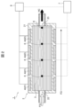
- FIG. 2 is a schematic cross-sectional view of a reactor of the hydrocarbon production apparatus in FIG. 1.
- 1 is a flow diagram illustrating an embodiment of a hydrocarbon production method according to the present disclosure.
- 3 is a graph showing the temperatures of the first and second temperature control sections of the hydrocarbon production apparatus of FIG. 2.
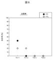
- 3 is a graph showing the reaction distribution of CO and CO 2 in the hydrocarbon production apparatus of FIG. 2. The graph which shows the reaction distribution of CO and CO2 in the hydrocarbon production apparatus of a comparative example.
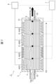
- FIG. 2 is a schematic cross-sectional view of a reactor showing Embodiment 2 of the hydrocarbon production apparatus according to the present disclosure.
- FIG. 8 is a graph showing the temperatures of the first, second, and third temperature control sections of the hydrocarbon production apparatus of FIG. 7.
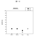
- 8 is a graph showing the reaction distribution of CO and CO 2 in the hydrocarbon production apparatus of FIG. 7.
- 7 is a graph showing the temperatures of the first, second, and third temperature control sections in Embodiment 3 of the hydrocarbon production apparatus according to the present disclosure.
- 7 is a graph showing the reaction distribution of CO and CO 2 in the hydrocarbon production apparatus of Embodiment 3.
- FIG. 3 is a schematic cross-sectional view showing a modification 1 of the hydrocarbon production apparatus shown in FIG. 2;
- FIG. 3 is a schematic cross-sectional view showing a second modification of the hydrocarbon production apparatus shown in FIG. 2;
- FIG. 1 is a block diagram showing Embodiment 1 of a hydrocarbon production apparatus according to the present disclosure.
- FIG. 2 is a schematic cross-sectional view of the reactor 2 of the hydrocarbon production apparatus 1 of FIG.
- the hydrocarbon production apparatus 1 of this embodiment is an apparatus that produces hydrocarbon HC by reacting raw material gas FG containing carbon monoxide (CO), carbon dioxide (CO 2 ), and hydrogen (H 2 ).
- Hydrocarbon HC produced by the hydrocarbon production apparatus 1 includes, for example, methane (CH 4 ).
- the hydrocarbon production apparatus 1 mainly includes a reactor 2, a catalyst 3, and a plurality of temperature control sections 4.
- the plurality of temperature adjustment sections 4 include, for example, one or more first temperature adjustment sections 41 and one or more second temperature adjustment sections 42.
- the hydrocarbon production apparatus 1 includes, for example, a solid oxide electrolysis cell (SOEC) 5 that generates a raw material gas FG from carbon dioxide and water vapor WV, as shown in FIG. Good too.
- SOEC solid oxide electrolysis cell
- the hydrocarbon production apparatus 1 may include, for example, a plurality of hydrocarbon sensors 6 and a control section 7, as shown in FIG.
- the reactor 2 includes, for example, a main body 21 that accommodates the catalyst 3, an inlet 22 into which a raw material gas FG containing carbon monoxide, carbon dioxide, and hydrogen is introduced, and an outlet 23 from which hydrocarbon HC is led out. have.
- the catalyst 3 is housed in the reactor 2 and reacts the raw material gas FG to generate hydrocarbon HC.
- the catalyst 3 constitutes a catalyst layer that produces methane by producing methanation reactions between carbon monoxide and hydrogen, and between carbon dioxide and hydrogen, as shown in reaction formulas (1) and (2) below, for example. are doing.
- the catalyst 3 commonly used nickel (Ni) can be used, for example.
- the catalyst 3 is made of, for example, platinum (Pt), ruthenium (Ru), rhodium (Rh), palladium (Pd), iron (Fe), cobalt (Co), copper (Cu), zinc (Zn), iridium (
- the catalytic metal may contain at least one selected from the group consisting of Ir), gold (Au), and silver (Ag).
- the catalyst 3 can further include, for example, a carrier on which a catalytic metal as described above is supported.
- Examples of the carrier for the catalyst 3 include SiO 2 , Al 2 O 3 , ZrO 2 , TiO 2 , MgO, cerium oxide (CeO 2 ), La 2 O 3 , ZnO, GeO 2 , SnO 2 , V 2 O 5 , It can be appropriately selected from metal oxides such as Y 2 O 3 , Nb 2 O 5 , MoO 3 , WO 3 and zeolite.
- the carrier may contain one type of these metal oxides alone or may contain two or more types of these metal oxides.
- the carrier preferably contains Al 2 O 3 .
- a carrier containing Al 2 O 3 does not exhibit unnecessary reactions during the reaction, is relatively stable, and has a large reaction surface area.
- the shape of the carrier of the catalyst 3 may be a general shape such as a granular shape such as a spherical shape or a columnar shape, or an irregular shape such as a honeycomb shape. Further, as the catalyst 3, a granular carrier can be suitably used.
- the specific surface area of the carrier of the catalyst 3 is, for example, preferably 30 m 2 /g or more, more preferably 100 m 2 /g or more. The reason for this is that the dispersibility and surface area of the catalytic metal supported on the carrier can be increased, and sufficient catalytic activity for methane production can be obtained.
- a catalyst precursor solution obtained by dissolving and mixing a catalyst metal precursor in a solvent such as water or ethanol is used.
- the precursor of the catalytic metal is not particularly limited, but for example, metal salts such as chlorides, nitrates, sulfates, and carbonates can be used.
- the method of supporting the catalyst metal on the carrier is not particularly limited, and for example, an impregnation method, a coprecipitation method, a polyol method, an electroless plating method, etc. can be employed.
- the amount of the catalytic metal supported on the carrier of the catalyst 3 is preferably within the range of 0.05% by weight to 30% by weight, in particular the weight ratio of the catalytic metal to the total weight of the carrier and the catalytic metal. It is preferably within the range of .0% to 10% by weight. The reason for this is that if the weight ratio is above the lower limit of the above range, the catalytic activity will be sufficient, and if the weight ratio is below the upper limit of the above range, the catalytic metal particles supported on the carrier will have agglomeration. This is because reduction in surface area is suppressed and desired catalytic activity can be obtained.
- the catalyst 3 may be used in combination with an adsorbent that adsorbs water (H 2 O) that is produced simultaneously with methane in order to increase the amount of methane produced.
- an adsorbent that adsorbs water H 2 O
- the generated water can be forcibly removed from the reaction system and the forward reaction can be promoted. This makes it possible to improve the conversion rate of carbon dioxide to methane.
- zeolite, activated carbon, metal salts, metal oxides, silica gel, activated alumina, etc. can be used as the adsorbent used in combination with the catalyst 3.
- zeolite is preferable. This is because the structure of zeolite suitable for the gas composition can be selected by changing its pore diameter and the ratio of SiO 2 and Al 2 O 3 that constitute the zeolite. Thereby, the conversion rate of carbon dioxide into methane by the catalyst metal supported on the carrier of the catalyst 3 can be improved.
- the shape of the zeolite is not particularly limited, and may be, for example, granular, such as spherical or columnar, or irregularly shaped, such as a honeycomb, but granular is preferable.
- the pore diameter of the zeolite used as an adsorbent used in combination with the catalyst 3 is preferably 3.6 ⁇ or more.
- the molecular size of water is 3.6 ⁇ , and if the pore diameter is smaller than this, it will be difficult to adsorb water and the desired effect of improving the conversion rate of carbon dioxide to methane will not be obtained.
- the crystal structure of the zeolite is not particularly limited, and any of the general A type, X type, LSX type, beta, ZSM, ferrierite, mordenite, L type, and Y type may be used.
- the method of mixing the carrier supporting the catalytic metal of the catalyst 3 and the zeolite as an adsorbent is not particularly limited, as long as the carrier supporting the catalytic metal and the zeolite are mixed uniformly.
- the mixing ratio of the carrier supporting the catalytic metal of the catalyst 3 and the zeolite as the adsorbent is, for example, preferably 3 to 5, with the weight of the carrier supporting the catalytic metal being 1 and the weight ratio of the zeolite being 3 to 5. If the weight ratio of the zeolite is lower than 3 relative to the weight of the carrier carrying the catalyst metal being 1, sufficient water adsorption performance may not be obtained and the carbon dioxide conversion rate may decrease.
- the weight of the carrier carrying the catalytic metal is 1 and the weight ratio of the zeolite is higher than 5, sufficient water adsorption performance can be obtained, but the zeolite becomes excessive and the weight ratio of the carrier carrying the catalytic metal and the zeolite becomes The conversion rate of carbon dioxide to methane per total weight may be reduced.
- first temperature control units 41 are provided on the outer circumference of the reactor 2, for example, on the upstream side of the center of the gas flow direction FD inside the reactor 2.
- two first temperature control units 41 are provided adjacent to each other at the most upstream part of the reactor 2 and the downstream side thereof in the gas flow direction FD.
- Each first temperature adjustment section 41 adjusts the temperature of the catalyst 3 on the upstream side in the gas flow direction FD inside the reactor 2 to a first temperature suitable for the reaction of carbon monoxide.
- the first temperature adjustment section 41 is configured by, for example, a heater whose temperature can be controlled. Note that the number of first temperature adjustment sections 41 is not particularly limited, and may be one or three or more.
- one or more second temperature adjustment units 42 are provided at the outer circumference of the reactor 2 on the downstream side of the center of the gas flow direction FD inside the reactor 2.
- two second temperature control units 42 are provided adjacent to each other at the most downstream part of the reactor 2 and its upstream side in the gas flow direction FD.
- Each second temperature adjustment section 42 adjusts the temperature of the catalyst 3 on the downstream side in the gas flow direction FD to a second temperature suitable for the reaction of carbon dioxide.
- the second temperature adjustment section 42 is configured by, for example, a heater whose temperature can be controlled. Note that the number of second temperature adjustment sections 42 is not particularly limited, and may be one or three or more.
- the SOEC 5 reacts a mixed gas of carbon dioxide (CO 2 ) and water vapor WV to generate a raw material gas FG containing carbon monoxide, carbon dioxide, and hydrogen. More specifically, in SOEC5, for example, the following reactions (3) to (8) occur, and a mixed gas of carbon dioxide and water vapor WV is converted into hydrogen, methane, water vapor, carbon monoxide, and carbon dioxide. A raw material gas FG containing is generated.
- CO 2 carbon dioxide
- water vapor WV water vapor WV
- the hydrocarbon sensors 6 are arranged, for example, on the downstream side of each first temperature adjustment section 41 and on the downstream side of each second temperature adjustment section 42 in the gas flow direction FD inside the reactor 2. are provided at a plurality of detection positions, respectively. Each hydrocarbon sensor 6 detects the amount of hydrocarbon inside the reactor 2 . More specifically, the hydrocarbon sensor 6 is, for example, a methane sensor that detects the amount of methane gas at each detection position inside the reactor 2.
- the control unit 7 is, for example, a control device including one or more microcontrollers and storage devices.
- the control unit 7 controls the temperatures of the first temperature adjustment unit 41 and the second temperature adjustment unit 42 by, for example, executing a program stored in a memory or a storage device using a central processing unit, thereby adjusting the temperature of the catalyst 3. Adjust. More specifically, the control unit 7 adjusts the first temperature by, for example, outputting a control signal to the power supply unit 8 that supplies power to each first temperature adjustment unit 41 and each second temperature adjustment unit 42.
- the temperature of each first temperature adjustment section 41 and each second temperature adjustment section 42 is controlled by controlling the electric power supplied to the adjustment section 41 and the second temperature adjustment section 42 .
- the control unit 7 obtains the detection results of the amount of hydrocarbons from each hydrocarbon sensor 6, for example. For example, the control unit 7 adjusts each first temperature adjustment unit 41 and each second temperature so as to reduce the difference in the amount of hydrocarbons at each of the plurality of detection positions detected by the hydrocarbon sensor 6.
- the temperature of the adjustment section 42 is controlled. More specifically, the control unit 7 controls each first temperature adjustment unit 41 and each second temperature adjustment unit 41 so as to reduce the difference in the amount of methane gas at each detection position detected by the hydrocarbon sensor 6 Controls the temperature of the temperature adjustment section 42.
- FIG. 3 is a flow diagram illustrating an embodiment of the hydrocarbon production method according to the present disclosure.
- the hydrocarbon production method P of this embodiment can be carried out by, for example, the hydrocarbon production apparatus 1 described above.
- the hydrocarbon production method P of the present embodiment includes, for example, as shown in FIG. It has
- step P1 the raw material gas FG is introduced into the reactor 2 containing the catalyst 3 that reacts the raw material gas FG containing carbon monoxide, carbon dioxide, and hydrogen to produce hydrocarbon HC.
- the ratio of carbon monoxide gas and carbon dioxide gas contained in the raw material gas FG is the same. That is, the ratio of carbon monoxide gas and carbon dioxide gas contained in the raw material gas FG is approximately 1:1.
- step P2 the temperature of the catalyst 3 on the upstream side in the gas flow direction FD inside the reactor 2 is adjusted to a first temperature suitable for the reaction of carbon monoxide, and the temperature of the catalyst 3 on the downstream side in the gas flow direction FD is adjusted to a first temperature suitable for the reaction of carbon monoxide.
- the temperature in step 3 is adjusted to a second temperature suitable for the reaction of carbon dioxide.
- the first temperature adjustment section 41 is capable of adjusting the temperature of the catalyst 3 on the upstream side in the gas flow direction FD to a first temperature suitable for the reaction of carbon monoxide.
- the second temperature adjustment section 42 sets the temperature of the catalyst 3 on the downstream side in the gas flow direction FD to a temperature that can be adjusted to a second temperature suitable for the reaction of carbon dioxide.
- FIG. 4 is a graph showing the temperatures of the first temperature control section 41 and the second temperature control section 42 of the hydrocarbon production apparatus 1 of FIG. 2.
- TC1-1 and TC1-2 on the horizontal axis of the graph in FIG. 4 are the two first temperature controls disposed at the most upstream and downstream sides in the gas flow direction FD of the reactor 2 shown in FIG. 2, respectively.
- TC2-1 and TC2-2 on the horizontal axis of the graph in FIG. 4 are the second temperature control section 42 on the upstream side and the most downstream side thereof in the gas flow direction FD of the reactor 2 in FIG. 2, respectively.
- the vertical axis of the graph in FIG. 4 is the set temperature T of each first temperature adjustment section 41 and each second temperature adjustment section 42.
- the set temperatures of the first temperature adjustment section 41 and the second temperature adjustment section 42 of the hydrocarbon production apparatus 1 of the present embodiment are represented by circles, and the hydrocarbon production apparatus according to the present disclosure is
- the set temperatures of the temperature control sections provided at positions corresponding to the first temperature control section 41 and the second temperature control section 42 of the hydrocarbon production apparatus 1 of the present embodiment are marked with an X. It is expressed as Note that the hydrocarbon production apparatus of the comparative example has the same configuration as the hydrocarbon production apparatus 1 of the present embodiment except for the set temperature of the temperature adjustment section.
- the set temperature T of the two first temperature control parts 41 (TC1-1, TC1-2) is set to about 264°C, and the two The set temperature T of the temperature control section 42 (TC2-1, TC2-2) is set to approximately 300° C., which is higher than that of the first temperature control section 41.
- the temperature of the catalyst 3 on the upstream side in the gas flow direction FD inside the reactor 2 is adjusted to the first temperature suitable for the reaction of carbon monoxide
- the temperature of the catalyst 3 on the downstream side in the gas flow direction FD is adjusted to the first temperature suitable for the reaction of carbon monoxide.
- the temperature is adjusted to a second temperature suitable for reaction of carbon dioxide.
- all temperature control sections are set at the same temperature of about 300° C. from the upstream side to the downstream side in the gas flow direction FD.
- FIG. 5 is a graph showing the reaction distribution of CO and CO 2 in the reactor 2 of the hydrocarbon production apparatus 1 of this embodiment.
- FIG. 6 is a graph showing the reaction distribution of CO and CO 2 in the reactor of the hydrocarbon production apparatus of the comparative example.
- TC1-1 to TC2-2 on the horizontal axis in FIGS. 5 and 6 indicate two first temperature adjustment sections 41 and two second temperature adjustment sections 42, as in FIG. 4 described above.
- the vertical axis in FIGS. 5 and 6 is the reaction rate between CO and CO2 .
- the catalyst 3 on the upstream side of the reactor 2 corresponding to the position of each first temperature control section 41 (TC1-1, TC1-2) According to the above reaction formula (1), carbon monoxide and hydrogen react to generate methane. Further, in the catalyst 3 on the downstream side of the reactor 2 corresponding to the position of each second temperature control part 42 (TC2-1, TC2-2), carbon dioxide and hydrogen react according to the above reaction formula (2). methane is produced.
- the amount of hydrocarbons inside the reactor 2 is detected at a plurality of detection positions downstream of the temperature adjustment section 42 .
- the control unit 7 adjusts each first temperature adjustment unit 41 and each second temperature so as to reduce the difference in the amount of hydrocarbons at each of the plurality of detection positions detected by the hydrocarbon sensor 6.
- the temperature of the adjustment section 42 is controlled.
- the hydrocarbon production method P of this embodiment includes, for example, a step P3 of determining whether to stop producing hydrocarbon HC.
- step P3 for example, when the operation of the hydrocarbon production apparatus 1 is stopped, it is determined to stop production of hydrocarbon HC (YES), and the flow of the hydrocarbon production method P shown in FIG. 3 ends.
- step P3 when the operation of the hydrocarbon production apparatus 1 is continued, it is determined in step P3 not to stop the production (NO), and steps P1 and P2 are repeated.
- the hydrocarbon production apparatus 1 of the present embodiment includes the reactor 2 into which the raw material gas FG is introduced, and the catalyst 3 accommodated in the reactor 2 and which reacts the raw material gas FG to produce hydrocarbons HC. , a plurality of temperature adjustment sections 4 , a plurality of hydrocarbon sensors 6 , and a control section 7 .
- a raw material gas FG is introduced into the reactor 2.
- a plurality of temperature adjustment units 4 are provided in the gas flow direction FD inside the reactor 2 to adjust the temperature of the catalyst 3.
- the plurality of hydrocarbon sensors 6 detect the amount of hydrocarbons inside the reactor 2 at a plurality of detection positions downstream of each of the plurality of temperature adjustment sections 4 .
- the control unit 7 controls the temperature of each temperature adjustment unit so as to reduce the difference in the amount of hydrocarbons at each of the plurality of detection positions detected by the hydrocarbon sensor.
- the hydrocarbon production apparatus 1 of this embodiment includes the reactor 2, the catalyst 3, one or more first temperature adjustment sections 41, and one or more second temperature adjustment sections 42. .
- a raw material gas FG containing carbon monoxide, carbon dioxide, and hydrogen is introduced into the reactor 2 .
- the catalyst 3 is housed in the reactor 2 and reacts the raw material gas FG to generate hydrocarbon HC.
- Each first temperature adjustment section 41 adjusts the temperature of the catalyst 3 on the upstream side in the gas flow direction FD inside the reactor 2 to a first temperature suitable for the reaction of carbon monoxide.
- Each second temperature adjustment section 42 adjusts the temperature of the catalyst 3 on the downstream side in the gas flow direction FD to a second temperature suitable for the reaction of carbon dioxide.
- the raw material gas FG is placed in a reactor 2 containing a catalyst 3 that reacts the raw material gas FG containing carbon monoxide, carbon dioxide, and hydrogen to produce hydrocarbon HC. will be introduced.
- the temperature of the catalyst 3 on the upstream side in the gas flow direction FD inside the reactor 2 is adjusted to a first temperature suitable for the reaction of carbon monoxide
- the temperature of the catalyst 3 on the downstream side in the gas flow direction FD is adjusted to a first temperature suitable for the reaction of carbon monoxide.
- the temperature is adjusted to a second temperature suitable for the reaction of carbon dioxide.
- the hydrocarbon production apparatus 1 of the present embodiment has a first temperature control section on the upstream side in the gas flow direction FD of the reactor 2, compared to the hydrocarbon production apparatus of the comparative example. 41 (TC1-1, TC1-2) can be lowered. Generally, the catalyst 3 deteriorates more as the temperature increases. Therefore, according to the hydrocarbon production apparatus 1 and the hydrocarbon production method P of the present embodiment, the reaction when producing hydrocarbon HC using the raw material gas FG containing carbon monoxide, carbon dioxide, and hydrogen can be uniformly performed. This makes it possible to save energy and suppress deterioration of the catalyst 3.
- CCS carbon capture and storage
- One means of this carbon cycle is to convert carbon dioxide into a resource. Recycling carbon dioxide means converting carbon dioxide into fuels and chemical products.
- the technology for converting carbon dioxide into hydrocarbons for the purpose of cyclical use is an extremely important technology in that it not only reduces carbon dioxide emissions but also prevents the emitted carbon dioxide from being diffused into the atmosphere.
- the hydrocarbon production apparatus 1 of the present embodiment can be equipped with a SOEC 5 that generates the raw material gas FG from carbon dioxide and water vapor WV.
- the hydrocarbon production apparatus 1 of the present embodiment can contribute to conversion to an energy system that prevents an increase in carbon dioxide in the atmosphere and to the recovery of carbon dioxide as a resource through the carbon cycle. .
- the hydrocarbon production apparatus 1 of this embodiment further includes a plurality of hydrocarbon sensors 6 and a control section 7.
- the hydrocarbon sensor 6 detects the amount of hydrocarbons inside the reactor 2 at a plurality of detection positions downstream of each first temperature adjustment section 41 and downstream of each second temperature adjustment section 42 in the gas flow direction FD. Detect.
- the control unit 7 controls each first temperature adjustment unit 41 and each second temperature adjustment unit so as to reduce the difference in the amount of hydrocarbons at each of the plurality of detection positions detected by the hydrocarbon sensor 6. Control the temperature of 42.
- the hydrocarbon production apparatus 1 of the present embodiment has a position corresponding to each first temperature control section 41 (TC1-1, TC1-2) and a position corresponding to each The reaction of the catalyst 3 at the position corresponding to the second temperature control section 42 (TC2-1, TC2-2) can be made more uniform.
- the set temperature of the first temperature adjustment section 41 can be lowered, resulting in energy saving. This can be achieved more reliably.
- the ratio of carbon monoxide gas and carbon dioxide gas contained in the raw material gas FG introduced into the reactor 2 is the same.
- the temperature can be lower than T.
- the hydrocarbon HC produced by reacting the raw material gas FG with the catalyst 3 is methane.
- carbon monoxide and hydrogen and carbon dioxide and hydrogen can be reacted, respectively, according to the above reaction formulas (1) and (2), and methane as a hydrocarbon HC can be produced.
- FIG. 7 is a schematic cross-sectional view of a reactor 2 showing Embodiment 2 of the hydrocarbon production apparatus according to the present disclosure.
- the hydrocarbon production apparatus 1 of this embodiment differs from the hydrocarbon production apparatus 1 of the above-described first embodiment in that the temperature adjustment section 4 includes one or more third temperature adjustment sections 43. Further, in the hydrocarbon production apparatus 1 of the present embodiment, the ratio of carbon monoxide gas and carbon dioxide gas contained in the raw material gas FG introduced into the reactor 2 is different, for example, at a ratio of 1:2. There is more carbon dioxide gas than carbon gas. Other points of the hydrocarbon production apparatus 1 of this embodiment are the same as those of the hydrocarbon production apparatus 1 of the above-described first embodiment, so similar parts are given the same reference numerals and explanations are omitted.
- the third temperature adjustment section 43 is arranged between the one or more first temperature adjustment sections 41 and the one or more second temperature adjustment sections 42 in the gas flow direction FD of the reactor 2. More specifically, as shown in FIG. 7, the third temperature control section 43 includes, for example, two first temperature control sections provided in the gas flow direction FD of the reactor 2 of Embodiment 1 shown in FIG. Of the sections 41, the temperature control section 41 is provided in place of the first temperature adjustment section 41 on the downstream side. The third temperature adjustment section 43 adjusts the temperature of the catalyst 3 to a third temperature suitable for the reaction of carbon monoxide and carbon dioxide.
- the hydrocarbon sensor 6 is connected to the downstream side of each first temperature adjustment section 41, the downstream side of each third temperature adjustment section 43, and each second temperature adjustment section.
- the amount of hydrocarbons inside the reactor 2 is detected at a plurality of detection positions downstream of the reactor 42 .
- the control unit 7 controls each first temperature adjustment unit 41 and each second temperature so as to reduce the difference in the amount of hydrocarbons at each of the plurality of detection positions detected by the hydrocarbon sensor 6.
- the temperature of the adjustment section 42 and each of the third temperature adjustment sections 43 is controlled.
- FIG. 8 is a graph showing the set temperatures T of the first temperature adjustment section 41, the second temperature adjustment section 42, and the third temperature adjustment section 43 of the hydrocarbon production apparatus 1 of FIG.
- FIG. 9 is a graph showing the reaction distribution of CO and CO2 in the reactor 2 of the hydrocarbon production apparatus 1 of FIG.
- FIG. 10 is a graph showing the reaction distribution of CO and CO 2 in the hydrocarbon production apparatus of the comparative example.
- TC1 and TC3 on the horizontal axis of the graphs in FIGS. 8 to 10 are arranged at the first temperature control section 41 at the most upstream part in the gas flow direction FD of the reactor 2 shown in FIG. 7, and at the downstream side thereof, respectively.
- TC2-1 and TC2-2 on the horizontal axis of the graphs in FIGS. 8 to 10 respectively represent the second temperature control section 42 on the upstream side and the downstream side thereof in the gas flow direction FD of the reactor 2 in FIG. This is the second temperature adjustment section 42 at the most downstream part.
- the set temperature T of the first temperature controller 41 (TC1) is set to approximately 264°C
- the set temperature T of the third temperature controller 43 (TC3) is set to approximately 264°C.
- T is set at approximately 252° C., which is lower than the set temperature T of the first temperature adjustment section 41.
- the set temperature T of the two second temperature control sections 42 (TC2-1, TC2-2) on the downstream side of the third temperature control section 43 is higher than that of the first temperature control section.
- the temperature is about 300°C, which is higher than 41°C.
- the temperature of the catalyst 3 on the downstream side including the most downstream part of the reactor 2 is adjusted to a second temperature suitable for the reaction of carbon dioxide.
- all temperature control sections are set at the same temperature of about 300° C. from the upstream side to the downstream side in the gas flow direction FD.
- the above-mentioned reaction According to formula (1), carbon monoxide and hydrogen react to generate methane. Furthermore, in the catalyst 3 on the upstream side of the reactor 2 corresponding to the position of the third temperature control section 43 (TC3) on the downstream side of the first temperature control section 41, the above reaction formulas (1) and (2) are applied. Methane is produced by the reactions of carbon monoxide and hydrogen, and carbon dioxide and hydrogen. Further, in the catalyst 3 on the downstream side of the reactor 2 corresponding to the position of each second temperature control part 42 (TC2-1, TC2-2), carbon dioxide and hydrogen react according to the above reaction formula (2). methane is produced.
- the hydrocarbon production apparatus 1 of this embodiment further includes one or more third temperature adjustment sections 43.
- the third temperature adjustment section 43 is disposed between one or more first temperature adjustment sections 41 and one or more second temperature adjustment sections 42 in the gas flow direction FD, and is arranged to adjust the temperature of the catalyst 3 to and a third temperature suitable for the reaction of carbon dioxide.
- the hydrocarbon production apparatus 1 of this embodiment can lower the temperature of the third temperature control section 43 (TC3) below the temperature of the first temperature control section 41.
- the catalyst 3 deteriorates more as the temperature increases. Therefore, according to the hydrocarbon production apparatus 1 and the hydrocarbon production method P of the present embodiment, the reaction when producing hydrocarbon HC using the raw material gas FG containing carbon monoxide, carbon dioxide, and hydrogen can be uniformly performed. This makes it possible to further save energy and further suppress deterioration of the catalyst 3.
- the hydrocarbon sensor 6 is connected to the downstream side of each first temperature adjustment section 41, the downstream side of each third temperature adjustment section 43, and each second temperature adjustment section.
- the amount of hydrocarbons inside the reactor 2 is detected at a plurality of detection positions downstream of the reactor 42 .
- the control unit 7 controls each first temperature adjustment unit 41 and each second temperature adjustment unit so as to reduce the difference in the amount of hydrocarbons at each of the plurality of detection positions detected by the hydrocarbon sensor 6. 42 and each third temperature adjustment section 43.
- the hydrocarbon production apparatus 1 of the present embodiment includes the first temperature control section 41 (TC1), the third temperature control section 43 (TC3), and each temperature control section 41 (TC1), as shown in the graph of FIG.
- the reaction of the catalyst 3 at the position corresponding to the two temperature control sections 42 (TC2-1, TC2-2) can be made more uniform.
- the set temperatures of the first temperature adjustment section 41 and the third temperature adjustment section 43 can be This makes it possible to more reliably achieve energy savings.
- the ratio of carbon monoxide gas and carbon dioxide gas contained in the raw material gas FG introduced into the reactor 2 is different.
- the set temperatures of the first temperature control section 41 and the third temperature control section 43 on the upstream side of the center of the reactor 2 in the gas flow direction FD are changed to the second temperature control section 41 and the third temperature control section 43.
- the temperature can be lower than the temperature of the temperature adjustment section 42.
- Embodiment 3 of the hydrocarbon production apparatus according to the present disclosure will be described with reference to FIGS. 2 and 7 and FIGS. 11 to 13.
- the hydrocarbon production apparatus 1 of this embodiment has a third temperature control section in place of the second temperature control section 42 on the upstream side among the two second temperature control sections 42 on the downstream side of the reactor 2 shown in FIG. 43 is different from the hydrocarbon production apparatus 1 of the above-described first and second embodiments shown in FIGS. 2 and 7.
- the carbon monoxide gas and carbon dioxide gas contained in the raw material gas FG are such that the carbon monoxide gas is larger than the carbon dioxide gas at a ratio of 2:1, for example.
- This is different from the hydrocarbon production apparatus 1 of the first and second embodiments described above.
- Other points of the hydrocarbon production apparatus 1 of this embodiment are the same as those of the hydrocarbon production apparatus 1 of the above-described embodiments 1 and 2, so similar parts are given the same reference numerals and explanations are omitted. .
- FIG. 11 is a graph showing the set temperatures T of the first temperature adjustment section 41, the second temperature adjustment section 42, and the third temperature adjustment section 43 in Embodiment 3 of the hydrocarbon production apparatus according to the present disclosure.
- FIG. 12 is a graph showing the reaction distribution of CO and CO 2 in the reactor 2 of the hydrocarbon production apparatus 1 of Embodiment 3.
- FIG. 13 is a graph showing the reaction distribution of CO and CO 2 in the hydrocarbon production apparatus of the comparative example.
- TC1-1 and TC1-2 on the horizontal axis of the graphs in FIGS. 11 to 13 are arranged at the first temperature control section 41 at the most upstream part in the gas flow direction FD of the reactor 2 shown in FIG. 2 and on the downstream side thereof. This is the first temperature adjustment section 41.
- TC3 and TC2 on the horizontal axes of the graphs in FIGS. 11 to 13 respectively represent the third temperature control section 43 disposed downstream of the two first temperature control sections 41 on the upstream side and the most downstream side thereof. This is a second temperature adjustment section 42 located downstream.
- the set temperature T of the two first temperature control sections 41 (TC1-1, TC1-2) on the upstream side is set to about 264°C.
- the set temperature T of the third temperature control section 43 (TC3) on the downstream side is set to about 258° C., which is lower than the set temperature T of the first temperature control section 41.
- the set temperature T of the second temperature control section 42 (TC2) at the most downstream part of the third temperature control section 43 is higher than that of the first temperature control section 41.
- the temperature is approximately 312°C.
- the temperature of the catalyst 3 at the most downstream part of the reactor 2 is adjusted to a second temperature suitable for the reaction of carbon dioxide.
- all temperature control sections are set at the same temperature of about 274° C. from the upstream side to the downstream side in the gas flow direction FD.
- the reactor 2 corresponding to the position of the two first temperature control parts 41 (TC1-1, TC1-2) on the upstream side is In the upstream catalyst 3, carbon monoxide and hydrogen react to generate methane according to the above reaction formula (1).
- the above reaction formula (1) and According to (2) carbon monoxide and hydrogen react, and carbon dioxide and hydrogen react to produce methane.
- FIG. 14 is a schematic cross-sectional view showing a modification 1 of the hydrocarbon production apparatus 1 of FIG. 2.
- the catalyst 3 inside the reactor 2 of the hydrocarbon production apparatus 1 is housed divided into a plurality of compartments.
- a pressure valve 9 is installed downstream of each compartment in which the catalyst 3 is accommodated.
- the pressure valve 9 is controlled, for example, by the control unit 7, and controls the pressure in the section where the catalyst 3 is accommodated on the upstream side of the pressure valve 9.
- the pressure in each compartment containing the catalyst 3 can be controlled to a pressure suitable for the methanation reaction of the above reaction formula (1) or (2), promoting the methanation reaction, It becomes possible to reduce the power consumption of the first temperature adjustment section 41 and the second temperature adjustment section 42 and promote energy saving.
- FIG. 15 is a schematic cross-sectional view showing a second modification of the hydrocarbon production apparatus 1 of FIG.
- the hydrocarbon production apparatus 1 includes a fourth temperature adjustment section 44 at an upstream position corresponding to each first temperature adjustment section 41 in the gas flow direction FD inside the reactor 2,
- a fifth temperature adjustment section 45 is provided at a downstream position corresponding to each second temperature adjustment section 42 .
- Each of the fourth temperature adjustment section 44 and each of the fifth temperature adjustment section 45 has a refrigerant flow path through which the refrigerant R flows.
- Each fourth temperature adjustment section 44 and each fifth temperature adjustment section 45 are provided around the catalyst 3, for example.
- the hydrocarbon production apparatus 1 includes, for example, a refrigerant supply section 10.
- the refrigerant supply section 10 supplies the refrigerant R to the refrigerant inlet of each of the fourth temperature adjustment section 44 and each of the fifth temperature adjustment section 45 via the refrigerant supply pipe 11, for example. Further, the refrigerant supply section 10 recovers the refrigerant discharged from the refrigerant outlet of each of the fourth temperature adjustment section 44 and each of the fifth temperature adjustment section 45, for example, via the refrigerant recovery pipe 12.
- the refrigerant supply section 10 is controlled by the control section 7, for example, and individually controls the flow rate of the refrigerant R supplied to each of the fourth temperature adjustment sections 44 and each of the fifth temperature adjustment sections 45.
- the one or more fourth temperature control units 44 cool the catalyst 3 to adjust the temperature of the catalyst 3 on the upstream side in the gas flow direction FD inside the reactor 2 to a level higher than that of carbon monoxide. Adjust the first temperature to be suitable for the reaction. Furthermore, the one or more fifth temperature adjustment units 45 cool the catalyst 3 to adjust the temperature of the catalyst 3 on the downstream side in the gas flow direction FD to a second temperature suitable for the reaction of carbon dioxide. According to this modification, by utilizing the heat generated by the methanation reaction of the above reaction formula (1) or (2), it is possible to reduce power consumption and achieve energy saving, while at the same time The temperature of the catalyst 3 can be controlled by the fifth temperature adjustment section 45.
- Example 10 Method for producing methanation catalyst> First, nickel nitrate raw material powder was weighed so as to have a concentration of 25% by weight as nickel metal, and put into an eggplant flask, and then 30 ml of pure water was added thereto. Next, Al 2 O 3 powder (specific surface area: 150 m 2 g ⁇ 1 ) was added as a carrier to give a concentration of 75% by weight, and the mixture was stirred in an evaporator for 20 minutes. Next, the pressure was reduced to 100 mbar, and the solvent was removed in a water bath at 80° C. while stirring to obtain a methanation catalyst precursor powder.
- Al 2 O 3 powder specific surface area: 150 m 2 g ⁇ 1
- the methanation catalyst precursor powder was uniformly ground in a mortar, placed in a quartz boat, and then held at 500° C. in an air atmosphere for 2 hours in a box furnace. Further, this powder was sized to a size of 0.5 to 1.0 mm to obtain a methanation catalyst.
- the methanation characteristics of the methanation reactor include a region where carbon dioxide (CO 2 ), hydrogen (H 2 ), and argon (Ar) gases, which are reaction gases, can flow and whose flow rate can be controlled.
- Methanation reaction equipment that has a heating furnace that can flow the reaction gas to the methanation reactor and heat the methane-containing gas and the methanation reactor, and a mass spectrometer (Thermo Star (registered trademark) manufactured by PFEIFFER VACUUM) It can be evaluated by using
- the temperature was raised to 500° C. at a rate of 10° C./min and maintained at 500° C. for about 0.5 h.
- the methanation catalyst is reduced by changing the argon (Ar) gas to Ar + 3% H 2 gas and maintaining it for 1 hour while flowing it at a flow rate of 100 ccm.
- the Ar+3% H 2 gas is changed to Ar gas, and the temperature is lowered to 200° C. at a rate of 10° C./min while flowing at a flow rate of 100 ccm.
- the Ar gas was changed to a mixed gas of Ar gas flow rate 26.0 ccm, H 2 gas flow rate 18.8 ccm, CO gas flow rate 2.5 ccm, and CO 2 gas flow rate 2.5 ccm, and the gas flow path was changed to methanation reaction.
- the reactor By changing the reactor to a bypass that does not pass this reaction tube, the mixed gas is allowed to flow through the bypass.
- the mass spectrometer is maintained at 150° C. in advance. Note that, in terms of chemical equilibrium, the methanation reaction has a high methane production efficiency at temperatures below 200 to 500°C, but is not particularly limited and can be carried out at temperatures higher than 500°C.
- the gas flow path is returned from the bypass to the methanation reactor where the catalyst is placed, and the upstream The temperature adjustment (heater) of each part is controlled while checking the amount of CH 4 produced in each downstream part using a mass spectrometer.
- Example 1 The gas flow rates were set as Ar gas flow rate 26.0 ccm, H 2 gas flow rate 18.8 ccm, CO gas flow rate 2.5 ccm, and CO 2 gas flow rate 2.5 ccm, and the gases were introduced into the methanation reactor, and the heater and CH 4 sensor were connected upstream. Four downstream locations were provided and the generated CH 4 gas was obtained while being controlled.
- Example 2 Same as Example 1 except that the gas flow rates were set to Ar gas flow rate of 26.0 ccm, H2 gas flow rate of 18.8 ccm, CO gas flow rate of 1.7 ccm, and CO2 gas flow rate of 3.3 ccm and introduced into the methanation reactor. CH 4 gas was obtained by the method.
- Example 3 Same as Example 1 except that the gas flow rates were 26.0 ccm of Ar gas flow rate, 18.8 ccm of H 2 gas flow rate, 3.3 ccm of CO gas flow rate, and 1.7 ccm of CO 2 gas flow rate and introduced into the methanation reactor. CH 4 gas was obtained by the method.
- Example 1 and Comparative Example 1 when the ratio of CO to CO 2 gas to be introduced was 1:1 were similar to the distributions of Embodiment 1 and Comparative Example shown in FIG. 4, respectively.
- the heater temperature of TC1-1 and TC1-2 was 264°C, and that of TC2-1 and TC2-2 was 300°C, whereas in Comparative Example 1, all of 1 to 4 were controlled at 300°C.
- the heater temperature was reduced by 36° C. in TC1-1 and TC1-2.
- the reaction distributions of each gas in Example 1 and Comparative Example 1 were the same as in Embodiment 1 shown in FIG. 5 and Comparative Example shown in FIG. 6, respectively. As shown in FIG.
- Example 5 in Example 1, CO reacted first, and CO 2 reacted downstream, and a uniform reaction was achieved as a whole.
- Comparative Example 1 shown in FIG. 6 the reaction of CO and CO 2 is biased toward the upstream side, and no reaction is observed on the downstream side TC2-1 and TC2-2, indicating that the catalyst is not functioning at all. became clear. From this result, it is possible to achieve uniform reactions and energy savings by dividing the temperature control of the present invention and dividing the CH4 sensor so that the amount of CH4 produced between each CH4 sensor is uniform. has been proven.
- Example 2 and Comparative Example 2 when the ratio of introduced CO and CO 2 gas was set to 1:2 were similar to the distributions of Embodiment 2 and Comparative Example shown in FIG. 8, respectively. Further, the reaction distributions of each gas in Example 2 and Comparative Example 2 were similar to those in Embodiment 2 shown in FIG. 9 and Comparative Example shown in FIG. 10, respectively. Furthermore, the heater temperature distributions of Example 3 and Comparative Example 3 when the ratio of CO to CO 2 gas to be introduced is 2:1 are similar to the distributions of Embodiment 3 and Comparative Example shown in FIG. 11, respectively. did. Further, the reaction distributions of each gas in Example 3 and Comparative Example 3 were similar to those in Embodiment 3 shown in FIG. 12 and Comparative Example shown in FIG. 13, respectively.
Landscapes
- Chemical & Material Sciences (AREA)
- Organic Chemistry (AREA)
- Engineering & Computer Science (AREA)
- Chemical Kinetics & Catalysis (AREA)
- Oil, Petroleum & Natural Gas (AREA)
- General Chemical & Material Sciences (AREA)
- Materials Engineering (AREA)
- Organic Low-Molecular-Weight Compounds And Preparation Thereof (AREA)
- Low-Molecular Organic Synthesis Reactions Using Catalysts (AREA)
- Catalysts (AREA)
Abstract
本開示は、原料ガスを使用して炭化水素を製造する際の反応を均一化することができ、省エネルギー化と触媒の劣化抑制が可能な炭化水素製造装置を提供する。本開示の一態様は、原料ガスFGが導入される反応器2と、反応器2に収容され、原料ガスFGを反応させて炭化水素HCを生成する触媒3と、複数の温度調節部4と、複数の炭化水素センサ6と、制御部7とを備える炭化水素製造装置1である。複数の温度調節部4は、反応器2の内部におけるガスの流れ方向FDに設けられて触媒3の温度を調節する。炭化水素センサ6は、複数の温度調節部4の各々の下流側の複数の検出位置で反応器2の内部の炭化水素量を検出する。制御部7は、炭化水素センサ6によって検出された複数の検出位置の各々の検出位置における炭化水素量の差を低減するように、各々の温度調節部4の温度を制御する。
Description
本開示は、炭化水素製造装置および炭化水素製造方法に関する。
従来から触媒反応装置、メタン製造装置、および炭化水素製造装置に関する発明が知られている(たとえば、下記特許文献1から3を参照)。
下記特許文献1に記載された従来の触媒反応装置は、触媒を用いて原料ガスから目的ガスを生成する触媒反応装置であり、反応流路と、媒体流路と、媒体供給装置と、を備えている(特許文献1、第0006段落、請求項1、要約、図1)。上記反応流路は、上記触媒が設けられると共に上記原料ガスが流通する。上記媒体流路は、上記反応流路の周囲に設けられ、上記触媒の雰囲気温度を等温雰囲気に設定するための温度調節媒体が流通する。上記媒体供給装置は、上記媒体流路に上記温度調節媒体を供給する。この触媒反応装置において、上記媒体流路は、複数の区分流路に分割されており、上記媒体供給装置は、複数の上記区分流路に対して上記温度調節媒体を個別に供給する。
下記特許文献2に記載された従来のメタン製造装置は、二酸化炭素と水素からメタンを製造するメタン製造装置であって、第1反応器と、第2反応器と、熱供給部と、を備えている(特許文献2、第0007段落、請求項1、要約、図1)。上記第1反応器は、メタン化触媒性能を有する触媒を収容し、供給源から供給された二酸化炭素と水素とを含む原料ガスを用いて、メタン化反応を生じさせる。上記第2反応器は、上記第1反応器の下流側に配置され、上記第1反応器で生成されたメタンを含む反応混合ガスを用いて、メタン化反応を生じさせる。上記熱供給部は、上記第1反応器と上記第2反応器のうち、一方の反応器で生じた熱を他方の反応器に供給する。
下記特許文献3に記載された従来の炭化水素製造装置は、第1反応器と、第2反応器と、熱媒体供給部と、を備えている(特許文献3、第0008段落、請求項1、要約)。上記第1反応器は、触媒を収容し、供給源から供給された原料ガスを用いて炭化水素化合物を生成する。上記第2反応器は、触媒を収容し、上記第1反応器で生成された炭化水素化合物を含む反応混合ガスを用いて炭化水素化合物を生成する。上記熱媒体供給部は、上記第2反応器の触媒と熱交換する熱媒体の流量が上記第1反応器の触媒と熱交換する熱媒体の流量より少なくなるように、上記第1反応器と上記第2反応器とに熱媒体を供給する。
上記従来の触媒反応装置は、原料ガスの導入部近傍の触媒で反応が集中するおそれがある。そのため、装置内での反応が不均一になり、エネルギー効率が低下するとともに触媒の劣化が早期に進行するおそれがある。
本開示は、反応を均一化することができ、省エネルギー化と触媒の劣化抑制が可能な炭化水素製造装置を提供する。
本開示の一態様は、原料ガスが導入される反応器と、前記反応器に収容され、前記原料ガスを反応させて炭化水素を生成する触媒と、前記反応器の内部におけるガスの流れ方向に設けられて前記触媒の温度を調節する複数の温度調節部と、前記複数の温度調節部の各々の下流側の複数の検出位置で前記反応器の内部の炭化水素量を検出する炭化水素センサと、前記炭化水素センサによって検出された前記複数の検出位置の各々の検出位置における炭化水素量の差を低減するように、各々の前記温度調節部の温度を制御する制御部と、を備えることを特徴とする炭化水素製造装置である。
本開示の上記一態様によれば、反応を均一化することができ、省エネルギー化と触媒の劣化抑制が可能な炭化水素製造装置を提供することができる。
以下、図面を参照して本開示に係る炭化水素製造装置および炭化水素製造方法の実施形態を説明する。
[実施形態1]
図1は、本開示に係る炭化水素製造装置の実施形態1を示すブロック図である。図2は、図1の炭化水素製造装置1の反応器2の概略的な断面図である。本実施形態の炭化水素製造装置1は、一酸化炭素(CO)と二酸化炭素(CO2)と水素(H2)を含有する原料ガスFGを反応させて炭化水素HCを製造する装置である。炭化水素製造装置1によって製造される炭化水素HCは、たとえば、メタン(CH4)を含む。
図1は、本開示に係る炭化水素製造装置の実施形態1を示すブロック図である。図2は、図1の炭化水素製造装置1の反応器2の概略的な断面図である。本実施形態の炭化水素製造装置1は、一酸化炭素(CO)と二酸化炭素(CO2)と水素(H2)を含有する原料ガスFGを反応させて炭化水素HCを製造する装置である。炭化水素製造装置1によって製造される炭化水素HCは、たとえば、メタン(CH4)を含む。
炭化水素製造装置1は、主に、反応器2と、触媒3と、複数の温度調節部4と、を備えている。複数の温度調節部4は、たとえば、一つ以上の第1温度調節部41と、一つ以上の第2温度調節部42とを含む。また、炭化水素製造装置1は、たとえば、図1に示すように、二酸化炭素と水蒸気WVから原料ガスFGを生成する固体酸化物形電気分解セル(SOEC:Solid Oxide Electrolysis Cell)5を備えていてもよい。さらに、炭化水素製造装置1は、たとえば、図2に示すように、複数の炭化水素センサ6と、制御部7とを備えていてもよい。
反応器2は、たとえば、触媒3を収容する本体部21と、一酸化炭素と二酸化炭素と水素を含有する原料ガスFGが導入される入口22と、炭化水素HCが導出される出口23とを有している。触媒3は、反応器2に収容され、原料ガスFGを反応させて炭化水素HCを生成する。触媒3は、たとえば、以下の反応式(1)および(2)に示すように、一酸化炭素と水素、および、二酸化炭素と水素のメタネーション反応を生じさせてメタンを製造する触媒層を構成している。
CO+3H2-206kJ/mol→CH4+H2O (1)
CO2+4H2-160kJ/mol→CH4+2H2O (2)
CO2+4H2-160kJ/mol→CH4+2H2O (2)
触媒3は、たとえば、一般的に使用されるニッケル(Ni)を用いることができる。また、触媒3は、たとえば、白金(Pt)、ルテニウム(Ru)、ロジウム(Rh)、パラジウム(Pd)、鉄(Fe)、コバルト(Co)、銅(Cu)、亜鉛(Zn)、イリジウム(Ir)、金(Au)、及び銀(Ag)からなる群から選択される少なくとも1種を含有する触媒金属を含むことができる。また、触媒3は、たとえば、上記のような触媒金属が担持された担体をさらに含むことができる。
触媒3の担体としては、たとえば、SiO2、Al2O3、ZrO2、TiO2、MgO、酸化セリウム(CeO2)、La2O3、ZnO、GeO2、SnO2、V2O5、Y2O3、Nb2O5、MoO3、WO3、ゼオライト等の金属酸化物の中から適宜選択することができる。担体は、これらの金属酸化物うちの1種を単独で含有するものでもよいし、2種以上を含有するものでもよい。上記担体としては、Al2O3を含有するものが好ましい。Al2O3を含有する担体は、反応時に不要な反応を示さず、比較的安定で、反応表面積が大きくなる。
触媒3の担体の形状は、たとえば、球状、柱状等の粒状、ハニカム等の異形状など、一般的な形状を採用することができる。また、触媒3は、粒状の担体を好適に用いることができる。触媒3の担体の比表面積は、たとえば、30m2/g以上であることが好ましく、100m2/g以上であることがより好ましい。その理由としては、担体に担持されている触媒金属の分散性および表面積を増大させることができ、メタンの製造に十分な触媒活性が得られるためである。
触媒3の担体に触媒金属を担持するには、たとえば、触媒金属の前駆体を、水、エタノール等の溶媒に溶解、混合することで得られる触媒前駆体溶液を用いる。触媒金属の前駆体としては、特に限定されないが、たとえば、塩化物、硝酸塩、硫酸塩、炭酸塩等の金属塩を使用することができる。触媒金属を担体に担持する方法は、特に限定されず、たとえば、含侵法、共沈法、ポリオール法、無電解めっき法などを採用することができる。
触媒3の担体への触媒金属の担持量は、たとえば、担体および触媒金属の合計重量に対する触媒金属の重量比で0.05重量%から30重量%までの範囲内であることが好ましく、特に1.0重量%から10重量%までの範囲内であることが好ましい。その理由は、上記重量比が上記範囲の下限以上であれば、触媒活性が十分になり、上記重量比が上記範囲の上限以下であれば、担体に担持した触媒金属の粒子同士の凝集による比表面積の低下が抑制され、所望の触媒活性が得られるからである。
触媒3は、メタンの製造量を増加させるために、メタンと同時に生成される水(H2O)を吸着する吸着材と併用しても良い。触媒3と水を吸着する吸着材を併用することで、生成された水を反応系内から強制的に除去し、正反応を促進することができる。これにより、二酸化炭素のメタンへの転化率を向上させることが可能となる。触媒3と併用する吸着材としては、たとえば、ゼオライト、活性炭、金属塩、金属酸化物、シリカゲル、活性アルミナなどを使用することができる。
触媒3と併用する吸着材としては、ゼオライトが好ましい。ゼオライトは、その細孔径やゼオライトを構成するSiO2とAl2O3比を変えることでガス組成に適した構造を選択することができるからである。それにより、触媒3の担体に担持された触媒金属による二酸化炭素のメタンへの転化率を向上させることができる。ゼオライトの形状は、特に限定されず、たとえば、球状もしくは柱状等の粒状またはハニカム等の異形状などでよいが、粒状であることが好ましい。
触媒3と併用する吸着材として用いるゼオライトの細孔径は、3.6Å以上であることが好ましい。水の分子サイズは3.6Åであり、これよりも細孔径が小さいと水を吸着し難く、所望の二酸化炭素のメタンへの転化率向上効果を得られない。ゼオライトの結晶構造は、特に限定されず、一般的なA型、X型、LSX型、ベータ、ZSM、フェリエライト、モルデナイト、L型、Y型のいずれを用いてもよい。触媒3の触媒金属を担持した担体と、吸着材としてのゼオライトの混合方法は、特に限定されず、触媒金属を担持した担体とゼオライトが均一に混ざればよい。
触媒3の触媒金属を担持した担体と吸着材としてのゼオライトとの混合割合は、たとえば、触媒金属を担持した担体の重量を1として、ゼオライトの重量比が3から5であることが望ましい。触媒金属を担持した担体の重量を1として、ゼオライトの重量比が3よりも低いと、十分な水吸着性能が得られず、二酸化炭素転化率が低下する可能性がある。一方、触媒金属を担持した担体の重量を1として、ゼオライトの重量比が5よりも高いと、水吸着性能は十分に得られるが、ゼオライトが過剰になり、触媒金属を担持した担体とゼオライトの合計重量あたりの二酸化炭素からメタンへの転化率が低下する可能性がある。
図2に示すように、第1温度調節部41は、たとえば、反応器2の内部のガスの流れ方向FDの中央よりも上流側において、反応器2の外周部に一つ以上が設けられている。図2に示す例において、ガスの流れ方向FDにおける反応器2の最上流部とその下流側に二つの第1温度調節部41が隣接して設けられている。各々の第1温度調節部41は、反応器2の内部におけるガスの流れ方向FDの上流側の触媒3の温度を、一酸化炭素の反応に適した第1温度に調節する。第1温度調節部41は、たとえば、温度制御が可能なヒータによって構成されている。なお、第1温度調節部41の数は、特に限定されず、一つでも三つ以上でもよい。
第2温度調節部42は、たとえば、反応器2の内部のガスの流れ方向FDの中央部よりも下流側において、反応器2の外周部に一つ以上が設けられている。図2に示す例において、ガスの流れ方向FDにおける反応器2の最下流部とその上流側に二つの第2温度調節部42が隣接して設けられている。各々の第2温度調節部42は、ガスの流れ方向FDの下流側の触媒3の温度を二酸化炭素の反応に適した第2温度に調節する。第2温度調節部42は、たとえば、温度制御が可能なヒータによって構成されている。なお、第2温度調節部42の数は、特に限定されず、一つでも三つ以上でもよい。
図1に示すように、SOEC5は、二酸化炭素(CO2)と水蒸気WVとの混合ガスを反応させて、一酸化炭素と二酸化炭素と水素を含有する原料ガスFGを生成する。より具体的には、SOEC5では、たとえば、以下の反応式(3)から(8)の反応が生じ、二酸化炭素と水蒸気WVの混合ガスから、水素、メタン、水蒸気、一酸化炭素、および二酸化炭素を含有する原料ガスFGが生成される。
H2O+2e-→H2+O2- (3)
CO2+4H2-160kJ/mol→CH4+2H2O (4)
CO2+2e-→CO+O2- (5)
H2+CO2→CO+H2O (6)
CO+3H2→CH4+H2O (7)
2CO→C+CO2 (8)
CO2+4H2-160kJ/mol→CH4+2H2O (4)
CO2+2e-→CO+O2- (5)
H2+CO2→CO+H2O (6)
CO+3H2→CH4+H2O (7)
2CO→C+CO2 (8)
図2に示すように、炭化水素センサ6は、たとえば、反応器2の内部のガスの流れ方向FDにおける各々の第1温度調節部41の下流側と各々の第2温度調節部42の下流側の複数の検出位置に、それぞれ設けられている。各々の炭化水素センサ6は、反応器2の内部の炭化水素量を検出する。より具体的には、炭化水素センサ6は、たとえば、反応器2の内部の各検出位置におけるメタンガスの量を検出するメタンセンサである。
制御部7は、たとえば、一つ以上のマイクロコントローラや記憶装置を備えた制御装置である。制御部7は、たとえば、メモリや記憶装置に記憶されたプログラムを中央処理装置によって実行することで、第1温度調節部41および第2温度調節部42の温度を制御して、触媒3の温度を調節する。より具体的には、制御部7は、たとえば、各々の第1温度調節部41と各々の第2温度調節部42に電力を供給する電源部8に制御信号を出力することで、第1温度調節部41および第2温度調節部42に供給される電力を制御して、各々の第1温度調節部41および各々の第2温度調節部42の温度を制御する。
制御部7は、たとえば、各々の炭化水素センサ6から炭化水素量の検出結果を取得する。制御部7は、たとえば、炭化水素センサ6によって検出された複数の検出位置の各々の検出位置における炭化水素量の差を低減するように、各々の第1温度調節部41と各々の第2温度調節部42の温度を制御する。より具体的には、制御部7は、たとえば、炭化水素センサ6によって検出された各々の検出位置におけるメタンガスの量の差を低減するように、各々の第1温度調節部41と各々の第2温度調節部42の温度を制御する。
図3は、本開示に係る炭化水素製造方法の一実施形態を示すフロー図である。本実施形態の炭化水素製造方法Pは、たとえば、前述の炭化水素製造装置1によって実施することができる。
以下では、本実施形態の炭化水素製造方法Pを説明しつつ、本開示に係る炭化水素製造装置とは異なる比較例の炭化水素製造装置との対比に基づいて、本実施形態の炭化水素製造装置1の作用を説明する。本実施形態の炭化水素製造方法Pは、たとえば、図3に示すように、反応器2に原料ガスFGを導入する工程P1と、反応器2に収容された触媒3の温度を調節する工程P2とを有している。
工程P1では、一酸化炭素と二酸化炭素と水素を含有する原料ガスFGを反応させて炭化水素HCを生成する触媒3が収容された反応器2に、原料ガスFGを導入する。ここでは、原料ガスFGに含まれる一酸化炭素ガスと二酸化炭素ガスの比率が同等であるものとする。すなわち、原料ガスFGに含まれる一酸化炭素ガスと二酸化炭素ガスの比率は、略1:1である。
工程P2では、反応器2の内部におけるガスの流れ方向FDの上流側の触媒3の温度を一酸化炭素の反応に適した第1温度に調節するとともに、ガスの流れ方向FDの下流側の触媒3の温度を二酸化炭素の反応に適した第2温度に調節する。より具体的には、炭化水素製造装置1において、第1温度調節部41は、ガスの流れ方向FDの上流側の触媒3の温度を一酸化炭素の反応に適した第1温度に調節可能な温度に設定する。また、第2温度調節部42は、ガスの流れ方向FDの下流側の触媒3の温度を二酸化炭素の反応に適した第2温度に調節可能な温度に設定する。
図4は、図2の炭化水素製造装置1の第1温度調節部41および第2温度調節部42の温度を示すグラフである。図4のグラフの横軸のTC1-1およびTC1-2は、それぞれ、図2に示す反応器2のガスの流れ方向FDにおける最上流部とその下流側に配置された二つの第1温度調節部41である。また、図4のグラフの横軸のTC2-1およびTC2-2は、それぞれ、図2の反応器2のガスの流れ方向FDにおける上流側の第2温度調節部42とその下流側の最下流部の第2温度調節部42である。
また、図4のグラフの縦軸は、各々の第1温度調節部41と、各々の第2温度調節部42の設定温度Tである。なお、図4のグラフにおいて、本実施形態の炭化水素製造装置1の第1温度調節部41および第2温度調節部42の設定温度を丸印で表し、本開示に係る炭化水素製造装置とは異なる比較例の炭化水素製造装置において、本実施形態の炭化水素製造装置1の第1温度調節部41および第2温度調節部42に対応する位置に設けられた温度調節部の設定温度をX印で表している。なお、比較例の炭化水素製造装置は、温度調節部の設定温度以外は、本実施形態の炭化水素製造装置1と同様の構成を有している。
図4に示すように、本実施形態の炭化水素製造装置1は、二つの第1温度調節部41(TC1-1,TC1-2)の設定温度Tが約264℃にされ、二つの第2温度調節部42(TC2-1,TC2-2)の設定温度Tが第1温度調節部41よりも高温の約300℃にされている。これにより、反応器2の内部におけるガスの流れ方向FDの上流側の触媒3の温度が一酸化炭素の反応に適した第1温度に調節され、ガスの流れ方向FDの下流側の触媒3の温度が二酸化炭素の反応に適した第2温度に調節される。これに対し、比較例の炭化水素製造装置は、ガスの流れ方向FDにおける上流側から下流側まで、すべての温度調節部が約300℃の同一の温度に設定されている。
図5は、本実施形態の炭化水素製造装置1の反応器2におけるCOとCO2の反応分布を示すグラフである。図6は、比較例の炭化水素製造装置の反応器におけるCOとCO2の反応分布を示すグラフである。図5および図6の横軸のTC1-1からTC2-2は、前述の図4と同様に、二つの第1温度調節部41と二つの第2温度調節部42を示している。図5および図6の縦軸は、COとCO2の反応率である。
図5に示すように、本実施形態の炭化水素製造装置1は、各々の第1温度調節部41(TC1-1,TC1-2)の位置に対応する反応器2の上流側の触媒3において、上記の反応式(1)により一酸化炭素と水素が反応してメタンが生成されている。また、各々の第2温度調節部42(TC2-1,TC2-2)の位置に対応する反応器2の下流側の触媒3において、上記の反応式(2)により二酸化炭素と水素が反応してメタンが生成されている。
一方、図6に示すように、比較例の炭化水素製造装置は、最上流の第1温度調節部41(TC1-1)の位置に対応する反応器の最上流部の触媒において、一酸化炭素と二酸化炭素の双方が水素と反応してメタンが生成されている。さらに、その下流側の第1温度調節部41(TC1-2)の位置に対応する反応器の上流側の触媒において、二酸化炭素が水素と反応してメタンが生成されている。しかし、各々の第2温度調節部42(TC2-1,TC2-2)の位置に対応する反応器の下流側の触媒において、一酸化炭素と二酸化炭素はいずれも反応していない。
また、図3に示す触媒の温度を調節する工程P2では、たとえば、図2に示す炭化水素センサ6によって、ガスの流れ方向FDにおける各々の第1温度調節部41の下流側と各々の第2温度調節部42の下流側の複数の検出位置で反応器2の内部の炭化水素量を検出する。制御部7は、たとえば、炭化水素センサ6によって検出された複数の検出位置の各々の検出位置における炭化水素量の差を低減するように、各々の第1温度調節部41と各々の第2温度調節部42の温度を制御する。
図3に示すように、本実施形態の炭化水素製造方法Pは、たとえば、炭化水素HCの製造停止を判定する工程P3を有している。工程P3では、たとえば、炭化水素製造装置1の運転が停止された場合に、炭化水素HCの製造停止(YES)が判定され、図3に示す炭化水素製造方法Pのフローが終了する。一方、炭化水素製造装置1の運転が継続されている場合には、工程P3において製造を停止しないこと(NO)が判定され、工程P1および工程P2が繰り返される。
以上のように、本実施形態の炭化水素製造装置1は、原料ガスFGが導入される反応器2と、反応器2に収容され、原料ガスFGを反応させて炭化水素HCを生成する触媒3と、複数の温度調節部4と、複数の炭化水素センサ6と、制御部7とを備えている。反応器2は、原料ガスFGが導入される。複数の温度調節部4は、反応器2の内部におけるガスの流れ方向FDに設けられて触媒3の温度を調節する。複数の炭化水素センサ6は、複数の温度調節部4の各々の下流側の複数の検出位置で反応器2の内部の炭化水素量を検出する。制御部7は、炭化水素センサによって検出された複数の検出位置の各々の検出位置における炭化水素量の差を低減するように、各々の温度調節部の温度を制御する。
換言すると、本実施形態の炭化水素製造装置1は、反応器2と、触媒3と、一つ以上の第1温度調節部41と、一つ以上の第2温度調節部42とを備えている。反応器2は、一酸化炭素と二酸化炭素と水素を含有する原料ガスFGが導入される。触媒3は、反応器2に収容され、原料ガスFGを反応させて炭化水素HCを生成する。各々の第1温度調節部41は、反応器2の内部におけるガスの流れ方向FDの上流側の触媒3の温度を一酸化炭素の反応に適した第1温度に調節する。各々の第2温度調節部42は、ガスの流れ方向FDの下流側の触媒3の温度を二酸化炭素の反応に適した第2温度に調節する。
また、本実施形態の炭化水素製造方法Pは、一酸化炭素と二酸化炭素と水素を含有する原料ガスFGを反応させて炭化水素HCを生成する触媒3が収容された反応器2に原料ガスFGを導入する。そして、反応器2の内部におけるガスの流れ方向FDの上流側の触媒3の温度を一酸化炭素の反応に適した第1温度に調節するとともに、ガスの流れ方向FDの下流側の触媒3の温度を二酸化炭素の反応に適した第2温度に調節する。
このような構成により、本実施形態の炭化水素製造装置1および炭化水素製造方法Pによれば、図5に示すように、反応器2の上流側の触媒3で一酸化炭素と水素を反応させ、反応器2の下流側の触媒3で二酸化炭素と水素を反応させることができる。その結果、本実施形態の炭化水素製造装置1および炭化水素製造方法Pによれば、図6に示す比較例の炭化水素製造装置の反応器と比較して、ガスの流れ方向FDにおける触媒3の全体で炭化水素HCを製造する反応を均一に生じさせることができる。
さらに、図4に示すように、本実施形態の炭化水素製造装置1は、比較例の炭化水素製造装置と比較して、反応器2のガスの流れ方向FDにおける上流側の第1温度調節部41(TC1-1,TC1-2)の温度を低下させることができる。一般に、触媒3は、高温になるほど劣化が進行する。したがって、本実施形態の炭化水素製造装置1および炭化水素製造方法Pによれば、一酸化炭素と二酸化炭素と水素を含有する原料ガスFGを使用して炭化水素HCを製造する際の反応を均一化することができ、省エネルギー化と触媒3の劣化抑制が可能になる。
近年、世界的な経済発展に伴い、産業、工業、農業等における二酸化炭素の排出量が急激に増加している。特に先進国では二酸化炭素の排出量抑制が急務となっており、その中でも発電に伴う二酸化炭素の排出量は非常に多く、大気中の二酸化炭素を増加させないためのエネルギーシステムへの転換が必要となっている。
さらに、エネルギーシステムにおいては、航空、船舶、長距離貨物、負荷調整用発電、製鉄、セメント等、電化や二酸化炭素回収貯留(CCS)による対応が困難な分野も存在する。これらの対応には、発電や燃料の利用で排出される二酸化炭素を取り除く「脱炭素」だけでなく、二酸化炭素を循環的に利用する「炭素循環」も求められている。
この炭素循環の一つの手段として、二酸化炭素の資源化がある。二酸化炭素の資源化とは、二酸化炭素を燃料や化成品に変換し利用することである。二酸化炭素の循環利用を目的とした炭化水素への変換技術は、二酸化炭素の排出量を削減するだけでなく、排出した二酸化炭素を大気中に拡散させないという点で非常に重要な技術である。
このような課題に対し、本実施形態の炭化水素製造装置1は、二酸化炭素と水蒸気WVから原料ガスFGを生成するSOEC5を備えることができる。このような構成により、本実施形態の炭化水素製造装置1は、大気中の二酸化炭素を増加させないためのエネルギーシステムへの転換、および炭素循環による二酸化炭素の資源化に貢献することが可能になる。
また、本実施形態の炭化水素製造装置1は、複数の炭化水素センサ6と、制御部7とをさらに備えている。炭化水素センサ6は、ガスの流れ方向FDにおける各々の第1温度調節部41の下流側と各々の第2温度調節部42の下流側の複数の検出位置で反応器2の内部の炭化水素量を検出する。制御部7は、炭化水素センサ6によって検出された複数の検出位置の各々の検出位置における炭化水素量の差を低減するように、各々の第1温度調節部41と各々の第2温度調節部42の温度を制御する。
このような構成により、本実施形態の炭化水素製造装置1は、図5のグラフに示すように、各々の第1温度調節部41(TC1-1,TC1-2)に対応する位置と各々の第2温度調節部42(TC2-1,TC2-2)に対応する位置における触媒3の反応をより均一にすることができる。その結果、ガスの流れ方向FDにおける触媒3の局所的な発熱を抑制して触媒3の劣化をさらに抑制することができるだけでなく、第1温度調節部41の設定温度を低下させ、省エネルギー化をより確実に実現することが可能になる。
また、本実施形態の炭化水素製造装置1において、反応器2に導入される原料ガスFGに含まれる一酸化炭素ガスと二酸化炭素ガスの比率は、同等である。このような場合、図2および図4に示すように、反応器2のガスの流れ方向FDにおける中央よりも上流側の第1温度調節部41の設定温度Tを第2温度調節部42の設定温度Tよりも低くすることができる。その結果、一酸化炭素ガスと二酸化炭素ガスを同率で含む原料ガスFGを使用して炭化水素HCを製造する際の反応を均一化することができ、省エネルギー化と触媒3の劣化抑制が可能になる。
また、本実施形態の炭化水素製造装置1において、触媒3によって原料ガスFGを反応させることで生成される炭化水素HCは、メタンである。これにより、上記の反応式(1)および(2)によって、一酸化炭素と水素、および、二酸化炭素と水素をそれぞれ反応させ、炭化水素HCとしてのメタンを生成することができる。
以上説明したように、本実施形態によれば、一酸化炭素と二酸化炭素と水素を含有する原料ガスFGを使用して炭化水素HCを製造する際の反応を均一化することができ、省エネルギー化と触媒3の劣化抑制が可能な炭化水素製造装置1および炭化水素製造方法Pを提供することができる。
[実施形態2]
次に、図7から図10を参照して、本開示に係る炭化水素製造装置の実施形態2を説明する。図7は、本開示に係る炭化水素製造装置の実施形態2を示す反応器2の概略的な断面図である。
次に、図7から図10を参照して、本開示に係る炭化水素製造装置の実施形態2を説明する。図7は、本開示に係る炭化水素製造装置の実施形態2を示す反応器2の概略的な断面図である。
本実施形態の炭化水素製造装置1は、温度調節部4が一つ以上の第3温度調節部43を含む点で、前述の実施形態1の炭化水素製造装置1と異なっている。また、本実施形態の炭化水素製造装置1において、反応器2に導入される原料ガスFGに含まれる一酸化炭素ガスと二酸化炭素ガスの比率は異なっており、たとえば1:2の比率で一酸化炭素ガスよりも二酸化炭素ガスの方が多い。本実施形態の炭化水素製造装置1のその他の点は、前述の実施形態1の炭化水素製造装置1と同様であるので、同様の部分には同一の符号を付して説明を省略する。
第3温度調節部43は、反応器2のガスの流れ方向FDにおいて一つ以上の第1温度調節部41と一つ以上の第2温度調節部42との間に配置されている。より具体的には、図7に示すように、第3温度調節部43は、たとえば、図2に示す実施形態1の反応器2のガスの流れ方向FDに設けられた二つの第1温度調節部41のうち、下流側の第1温度調節部41に替えて設けられている。第3温度調節部43は、触媒3の温度を一酸化炭素および二酸化炭素の反応に適した第3温度に調節する。
また、本実施形態の炭化水素製造装置1において、炭化水素センサ6は、各々の第1温度調節部41の下流側と各々の第3温度調節部43の下流側と各々の第2温度調節部42の下流側の複数の検出位置において、反応器2の内部の炭化水素量を検出する。また、制御部7は、炭化水素センサ6によって検出された複数の検出位置の各々の検出位置における炭化水素量の差を低減するように、各々の第1温度調節部41と各々の第2温度調節部42と各々の第3温度調節部43のそれぞれの温度を制御する。
図8は、図7の炭化水素製造装置1の第1温度調節部41、第2温度調節部42、および第3温度調節部43の設定温度Tを示すグラフである。図9は、図7の炭化水素製造装置1の反応器2におけるCOとCO2の反応分布を示すグラフである。図10は、比較例の炭化水素製造装置におけるCOとCO2の反応分布を示すグラフである。
図8から図10のグラフの横軸のTC1およびTC3は、それぞれ、図7に示す反応器2のガスの流れ方向FDにおける最上流部の第1温度調節部41とその下流側に配置された第3温度調節部43である。また、図8から図10のグラフの横軸のTC2-1およびTC2-2は、それぞれ、図7の反応器2のガスの流れ方向FDにおける上流側の第2温度調節部42とその下流側の最下流部の第2温度調節部42である。
図8に示すように、本実施形態の炭化水素製造装置1は、第1温度調節部41(TC1)の設定温度Tが約264℃にされ、第3温度調節部43(TC3)の設定温度Tは、第1温度調節部41の設定温度Tよりも低い約252℃にされている。これにより、反応器2の内部におけるガスの流れ方向FDの最上流部の触媒3の温度が一酸化炭素の反応に適した第1温度に調節され、その下流側の触媒3の温度が一酸化炭素および二酸化炭素の反応に適した第3温度に調節される。
さらに、本実施形態の炭化水素製造装置1は、第3温度調節部43の下流側の二つの第2温度調節部42(TC2-1,TC2-2)の設定温度Tが第1温度調節部41よりも高温の約300℃にされている。これにより、反応器2の最下流部を含む下流側の触媒3の温度が、二酸化炭素の反応に適した第2温度に調節される。これに対し、比較例の炭化水素製造装置は、ガスの流れ方向FDにおける上流側から下流側まで、すべての温度調節部が約300℃の同一の温度に設定されている。
その結果、図9に示すように、本実施形態の炭化水素製造装置1は、第1温度調節部41(TC1)の位置に対応する反応器2の最上流部の触媒3において、上記の反応式(1)により一酸化炭素と水素が反応してメタンが生成されている。また、第1温度調節部41よりも下流側の第3温度調節部43(TC3)の位置に対応する反応器2の上流側の触媒3において、上記の反応式(1)および(2)により一酸化炭素と水素、および、二酸化炭素と水素が反応してメタンが生成されている。さらに、各々の第2温度調節部42(TC2-1,TC2-2)の位置に対応する反応器2の下流側の触媒3において、上記の反応式(2)により二酸化炭素と水素が反応してメタンが生成されている。
一方、図10に示すように、比較例の炭化水素製造装置は、最上流の第1温度調節部41(TC1)の位置に対応する反応器の最上流部の触媒において、一酸化炭素と二酸化炭素の双方が水素と反応してメタンが生成されている。さらに、その下流側の第3温度調節部43(TC3)とその下流側の第2温度調節部42(TC2-1)の位置に対応する反応器の触媒において、二酸化炭素が水素と反応してメタンが生成されている。しかし、最下流部の第2温度調節部42(TC2-2)の位置に対応する反応器の最下流部の触媒において、一酸化炭素と二酸化炭素はいずれも反応していない。
以上のように、本実施形態の炭化水素製造装置1は、一つ以上の第3温度調節部43をさらに備えている。第3温度調節部43は、ガスの流れ方向FDにおいて一つ以上の第1温度調節部41と一つ以上の第2温度調節部42との間に配置されて触媒3の温度を一酸化炭素および二酸化炭素の反応に適した第3温度に調節する。
このような構成により、本実施形態の炭化水素製造装置1によれば、図9に示すように、反応器2の最上流部の触媒3で一酸化炭素と水素を反応させ、その下流側の触媒3で一酸化炭素と水素、および、二酸化炭素と水素を反応させ、さらにその下流側の触媒3で二酸化炭素と水素を反応させることができる。その結果、本実施形態の炭化水素製造装置1および炭化水素製造方法Pによれば、図10に示す比較例の炭化水素製造装置の反応器と比較して、ガスの流れ方向FDにおける触媒3の全体で炭化水素HCを製造する反応を均一に生じさせることができる。
さらに、図8に示すように、本実施形態の炭化水素製造装置1は、第3温度調節部43(TC3)の温度を第1温度調節部41の温度よりも低下させることができる。一般に、触媒3は、高温になるほど劣化が進行する。したがって、本実施形態の炭化水素製造装置1および炭化水素製造方法Pによれば、一酸化炭素と二酸化炭素と水素を含有する原料ガスFGを使用して炭化水素HCを製造する際の反応を均一化することができ、さらなる省エネルギー化と、さらなる触媒3の劣化抑制が可能になる。
また、本実施形態の炭化水素製造装置1において、炭化水素センサ6は、各々の第1温度調節部41の下流側と各々の第3温度調節部43の下流側と各々の第2温度調節部42の下流側の複数の検出位置において、反応器2の内部の炭化水素量を検出する。制御部7は、炭化水素センサ6によって検出された複数の検出位置の各々の検出位置における炭化水素量の差を低減するように、各々の第1温度調節部41と各々の第2温度調節部42と各々の第3温度調節部43のそれぞれの温度を制御する。
このような構成により、本実施形態の炭化水素製造装置1は、図9のグラフに示すように、第1温度調節部41(TC1)、第3温度調節部43(TC3)、および各々の第2温度調節部42(TC2-1,TC2-2)に対応する位置における触媒3の反応をより均一にすることができる。その結果、ガスの流れ方向FDにおける触媒3の局所的な発熱を抑制して触媒3の劣化をさらに抑制することができるだけでなく、第1温度調節部41および第3温度調節部43の設定温度を低下させ、省エネルギー化をより確実に実現することが可能になる。
また、本実施形態の炭化水素製造装置1において、反応器2に導入される原料ガスFGに含まれる一酸化炭素ガスと二酸化炭素ガスの比率が異なっている。このような場合、図7および図8に示すように、反応器2のガスの流れ方向FDにおける中央よりも上流側の第1温度調節部41および第3温度調節部43の設定温度を第2温度調節部42の温度よりも低くすることができる。その結果、一酸化炭素ガスと二酸化炭素ガスを異なる比率で含む原料ガスFGを使用して炭化水素HCを製造する際の反応を均一化することができ、省エネルギー化と触媒3の劣化抑制が可能になる。
以上説明したように、本実施形態によれば、一酸化炭素と二酸化炭素と水素を含有する原料ガスFGを使用して炭化水素HCを製造する際の反応を均一化することができ、省エネルギー化と触媒3の劣化抑制が可能な炭化水素製造装置1および炭化水素製造方法Pを提供することができる。
[実施形態3]
次に、図2および図7ならびに図11から図13を参照して、本開示に係る炭化水素製造装置の実施形態3を説明する。本実施形態の炭化水素製造装置1は、図2に示す反応器2の下流側の二つの第2温度調節部42のうち、上流側の第2温度調節部42に替えて第3温度調節部43を備える点で、図2および図7に示す前述の実施形態1および2の炭化水素製造装置1と異なっている。
次に、図2および図7ならびに図11から図13を参照して、本開示に係る炭化水素製造装置の実施形態3を説明する。本実施形態の炭化水素製造装置1は、図2に示す反応器2の下流側の二つの第2温度調節部42のうち、上流側の第2温度調節部42に替えて第3温度調節部43を備える点で、図2および図7に示す前述の実施形態1および2の炭化水素製造装置1と異なっている。
また、本実施形態の炭化水素製造装置1において、原料ガスFGに含まれる一酸化炭素ガスと二酸化炭素ガスは、たとえば2:1の比率で一酸化炭素ガスが二酸化炭素ガスよりも多い点で、前述の実施形態1および2の炭化水素製造装置1と異なっている。本実施形態の炭化水素製造装置1のその他の点は、前述の実施形態1および2の炭化水素製造装置1と同様であるので、同様の部分には同一の符号を付して説明を省略する。
図11は、本開示に係る炭化水素製造装置の実施形態3における第1温度調節部41、第2温度調節部42、および第3温度調節部43の設定温度Tを示すグラフである。図12は、実施形態3の炭化水素製造装置1の反応器2におけるCOとCO2の反応分布を示すグラフである。図13は、比較例の炭化水素製造装置におけるCOとCO2の反応分布を示すグラフである。
図11から図13のグラフの横軸のTC1-1およびTC1-2は、図2に示す反応器2のガスの流れ方向FDにおける最上流部の第1温度調節部41とその下流側に配置された第1温度調節部41である。また、図11から図13のグラフの横軸のTC3とTC2は、それぞれ、上流側の二つの第1温度調節部41の下流側に配置された第3温度調節部43とその下流側の最下流部に配置された第2温度調節部42である。
図11に示すように、本実施形態の炭化水素製造装置1は、上流側の二つの第1温度調節部41(TC1-1,TC1-2)の設定温度Tが約264℃にされ、その下流側の第3温度調節部43(TC3)の設定温度Tは、第1温度調節部41の設定温度Tよりも低い約258℃にされている。これにより、反応器2の内部におけるガスの流れ方向FDの上流側の触媒3の温度が一酸化炭素の反応に適した第1温度に調節され、その下流側の触媒3の温度が一酸化炭素および二酸化炭素の反応に適した第3温度に調節される。
さらに、本実施形態の炭化水素製造装置1は、第3温度調節部43の下流側の最下流部の第2温度調節部42(TC2)の設定温度Tが第1温度調節部41よりも高温の約312℃にされている。これにより、反応器2の最下流部の触媒3の温度が、二酸化炭素の反応に適した第2温度に調節される。これに対し、比較例の炭化水素製造装置は、ガスの流れ方向FDにおける上流側から下流側まで、すべての温度調節部が約274℃の同一の温度に設定されている。
その結果、図12に示すように、本実施形態の炭化水素製造装置1は、上流側の二つの第1温度調節部41(TC1-1,TC1-2)の位置に対応する反応器2の上流側の触媒3において、上記の反応式(1)により一酸化炭素と水素が反応してメタンが生成されている。また、上流側の二つの第1温度調節部41の下流側の第3温度調節部43(TC3)の位置に対応する反応器2の下流側の触媒3において、上記の反応式(1)および(2)により一酸化炭素と水素、および、二酸化炭素と水素が反応してメタンが生成されている。
さらに、反応器2の最下流部の第2温度調節部42(TC2)の位置に対応する反応器2の最下流部の触媒3において、上記の反応式(2)により二酸化炭素と水素が反応してメタンが生成されている。したがって、本実施形態の炭化水素製造装置1によれば、原料ガスFGに含まれる一酸化炭素ガスが原料ガスFGに含まれる二酸化炭素ガスよりも多い場合でも、前述の実施形態2の炭化水素製造装置1と同様の効果を奏することができる。
一方、図13に示すように、比較例の炭化水素製造装置は、最上流部の第1温度調節部41(TC1-1)の位置に対応する反応器の最上流部の触媒において、多くの二酸化炭素が水素と反応してメタンが生成されている。また、その最上流部の第1温度調節部41の下流側の第1温度調節部41(TC1-2)の位置に対応する反応器の上流側の触媒において、二酸化炭素と、二酸化炭素と比較して僅かな一酸化炭素とが、それぞれ水素と反応してメタンが生成されている。
さらに、その第1温度調節部41の下流側の第3温度調節部43(TC3)の位置に対応する反応器の下流側の触媒において、少量の一酸化炭素が水素と反応してメタンが生成されている。しかし、最下流部の第2温度調節部42(TC2)の位置に対応する反応器の最下流部の触媒において、一酸化炭素と二酸化炭素はいずれも反応していない。すなわち、比較例の炭化水素製造装置では、反応器の最下流部の触媒が機能せず、反応が上流側に偏っていることから、本実施形態の炭化水素製造装置1と比較して、触媒の局所的な劣化が進行し、電力消費量が増加するおそれがある。
最後に、図14および図15を参照して、図2に示す実施形態1の炭化水素製造装置1の変形例を説明する。
[変形例1]
図14は、図2の炭化水素製造装置1の変形例1を示す概略的な断面図である。本変形例において、炭化水素製造装置1の反応器2の内部の触媒3は、複数の区画に分割して収容されている。また、触媒3が収容された各々の区画の下流側には、圧力弁9が設置されている。圧力弁9は、たとえば、制御部7によって制御され、圧力弁9の上流側の触媒3が収容された区画の圧力を制御する。このような構成により、触媒3が収容された各区画の圧力を上記の反応式(1)または(2)のメタネーション反応に適した圧力に制御することができ、メタネーション反応を促進させ、第1温度調節部41および第2温度調節部42の消費電力を低減して省エネルギー化を促進することが可能になる。
図14は、図2の炭化水素製造装置1の変形例1を示す概略的な断面図である。本変形例において、炭化水素製造装置1の反応器2の内部の触媒3は、複数の区画に分割して収容されている。また、触媒3が収容された各々の区画の下流側には、圧力弁9が設置されている。圧力弁9は、たとえば、制御部7によって制御され、圧力弁9の上流側の触媒3が収容された区画の圧力を制御する。このような構成により、触媒3が収容された各区画の圧力を上記の反応式(1)または(2)のメタネーション反応に適した圧力に制御することができ、メタネーション反応を促進させ、第1温度調節部41および第2温度調節部42の消費電力を低減して省エネルギー化を促進することが可能になる。
[変形例2]
図15は、図2の炭化水素製造装置1の変形例2を示す概略的な断面図である。本変形例において、炭化水素製造装置1は、反応器2の内部のガスの流れ方向FDにおいて、各々の第1温度調節部41に対応する上流側の位置に第4温度調節部44を備え、各々の第2温度調節部42に対応する下流側の位置に第5温度調節部45を備えている。各々の第4温度調節部44および各々の第5温度調節部45は、内部に冷媒Rを流通させる冷媒流路を有している。各々の第4温度調節部44および各々の第5温度調節部45は、たとえば、触媒3の周囲に設けられている。
図15は、図2の炭化水素製造装置1の変形例2を示す概略的な断面図である。本変形例において、炭化水素製造装置1は、反応器2の内部のガスの流れ方向FDにおいて、各々の第1温度調節部41に対応する上流側の位置に第4温度調節部44を備え、各々の第2温度調節部42に対応する下流側の位置に第5温度調節部45を備えている。各々の第4温度調節部44および各々の第5温度調節部45は、内部に冷媒Rを流通させる冷媒流路を有している。各々の第4温度調節部44および各々の第5温度調節部45は、たとえば、触媒3の周囲に設けられている。
また、炭化水素製造装置1は、たとえば、冷媒供給部10を備えている。冷媒供給部10は、たとえば、冷媒供給管11を介して各々の第4温度調節部44および各々の第5温度調節部45の冷媒入口へ冷媒Rを供給する。また、冷媒供給部10は、たとえば、冷媒回収管12を介して、各々の第4温度調節部44および各々の第5温度調節部45の冷媒出口から排出された冷媒を回収する。冷媒供給部10は、たとえば、制御部7によって制御され、各々の第4温度調節部44と各々の第5温度調節部45に供給する冷媒Rの流量を個別に制御する。
このような構成により、一つ以上の第4温度調節部44は、触媒3を冷却することで、反応器2の内部におけるガスの流れ方向FDの上流側の触媒3の温度を一酸化炭素の反応に適した第1温度に調節する。また、一つ以上の第5温度調節部45は、触媒3を冷却することで、ガスの流れ方向FDの下流側の触媒3の温度を二酸化炭素の反応に適した第2温度に調節する。本変形例によれば、上記の反応式(1)または(2)のメタネーション反応の発熱を利用することで、消費電力を低減して省エネルギー化を達成しつつ、第4温度調節部44および第5温度調節部45によって触媒3の温度を制御することが可能になる。
以上、図面を用いて本開示に係る炭化水素製造装置および炭化水素製造方法の実施形態およびその変形例を詳述してきたが、具体的な構成はこの実施形態に限定されるものではなく、本開示の要旨を逸脱しない範囲における設計変更等があっても、それらは本開示に含まれるものである。
[実施例]
<メタネーション触媒の製造方法>
まず、硝酸ニッケル原料粉末を、ニッケル金属として25重量%になるよう秤量し、ナスフラスコに入れた後、30mlの純水を加えた。次に、75重量%になるようにAl2O3粉末(比表面積:150m2g-1)を担体として加え、エバポレータにて20分間撹拌した。次に、100mbarまで減圧し、撹拌しながら80℃の湯浴中で溶媒を除去することでメタネーション触媒前駆体粉末を得た。次に、メタネーション触媒前駆体粉末を乳鉢で均一に粉砕し、石英ボートへ入れた後、ボックス炉にて大気雰囲気下500℃で2時間保持した。さらにこの粉末を0.5~1.0mmのサイズに整粒し、メタネーション触媒を得た。
<メタネーション触媒の製造方法>
まず、硝酸ニッケル原料粉末を、ニッケル金属として25重量%になるよう秤量し、ナスフラスコに入れた後、30mlの純水を加えた。次に、75重量%になるようにAl2O3粉末(比表面積:150m2g-1)を担体として加え、エバポレータにて20分間撹拌した。次に、100mbarまで減圧し、撹拌しながら80℃の湯浴中で溶媒を除去することでメタネーション触媒前駆体粉末を得た。次に、メタネーション触媒前駆体粉末を乳鉢で均一に粉砕し、石英ボートへ入れた後、ボックス炉にて大気雰囲気下500℃で2時間保持した。さらにこの粉末を0.5~1.0mmのサイズに整粒し、メタネーション触媒を得た。
<メタネーション反応器のメタネーション特性評価方法>
実施形態に係るメタネーション反応器のメタネーション特性は、反応ガスである二酸化炭素(CO2)と水素(H2)、アルゴン(Ar)ガスの流通可能かつ流量制御可能な部位を有し、その反応ガスをメタネーション反応器へ流通させ、かつメタン含有ガスおよびメタネーション反応器を加熱可能な加熱炉を有したメタネーション反応設備と、質量分析計(PFEIFFER VACUUM社製Thermo Star(登録商標))を用いることにより評価することができる。
実施形態に係るメタネーション反応器のメタネーション特性は、反応ガスである二酸化炭素(CO2)と水素(H2)、アルゴン(Ar)ガスの流通可能かつ流量制御可能な部位を有し、その反応ガスをメタネーション反応器へ流通させ、かつメタン含有ガスおよびメタネーション反応器を加熱可能な加熱炉を有したメタネーション反応設備と、質量分析計(PFEIFFER VACUUM社製Thermo Star(登録商標))を用いることにより評価することができる。
まず、約0.015gのグラスウールを丸めてメタネーション反応器に入れた後、メタネーション触媒を約10cc秤量してSUS316製のメタネーション反応器に入れ、その反応器をメタネーション反応設備に設置する。
次に、メタネーション反応器にアルゴン(Ar)ガスを流量100ccmで流通させながら、10℃/minで500℃まで昇温し500℃で約0.5h保持する。次に、アルゴン(Ar)ガスをAr+3%H2ガスに変更し、流量100ccmで流通させながら、1h保持することにより、メタネーション触媒を還元する。
次に、Ar+3%H2ガスをArガスに変更し、流量100ccmで流通させながら、10℃/minで200℃まで降温する。次に、Arガスを、Arガス流量26.0ccm、H2ガス流量18.8ccm、COガス流量2.5ccm、CO2ガス流量2.5ccmの混合ガスに変更し、ガス流通経路をメタネーション反応器からこの反応管を通さないバイパスに変更することで、バイパスに混合ガスを流通させる。そして、このように混合ガスをバイパス経由で流通させた上で、バイパスの出口における混合ガス中の各m/zのイオン電流値を質量分析計により測定することで、触媒反応の影響を受けない混合ガス中の各m/zのイオン電流値を得る。なお、質量分析計は、予め150℃に保持しておく。なお、メタネーション反応は、化学平衡上、200~500℃以下でのメタン製造効率が高いが、特に限定されることはなく、500℃よりも高い温度においても実施することが可能である。
次に、上述のように触媒反応の影響を受けない混合ガス中の各m/zのイオン電流値を得た後、ガス流通経路をバイパスから触媒が配置されたメタネーション反応器に戻し、上流下流各部でのCH4生成量を各々質量分析計にて確認しつつ、各部の温調(ヒータ)を制御する。
[実施例1]
ガス流量を、Arガス流量26.0ccm、H2ガス流量18.8ccm、COガス流量2.5ccm、CO2ガス流量2.5ccmとし、メタネーション反応器に導入し、ヒータ、CH4センサを上流下流4か所設け、制御しつつ、生成したCH4ガスを得た。
ガス流量を、Arガス流量26.0ccm、H2ガス流量18.8ccm、COガス流量2.5ccm、CO2ガス流量2.5ccmとし、メタネーション反応器に導入し、ヒータ、CH4センサを上流下流4か所設け、制御しつつ、生成したCH4ガスを得た。
[実施例2]
ガス流量を、Arガス流量26.0ccm、H2ガス流量18.8ccm、COガス流量1.7ccm、CO2ガス流量3.3ccmとし、メタネーション反応器に導入したこと以外は実施例1と同様の方法でCH4ガスを得た。
ガス流量を、Arガス流量26.0ccm、H2ガス流量18.8ccm、COガス流量1.7ccm、CO2ガス流量3.3ccmとし、メタネーション反応器に導入したこと以外は実施例1と同様の方法でCH4ガスを得た。
[実施例3]
ガス流量を、Arガス流量26.0ccm、H2ガス流量18.8ccm、COガス流量3.3ccm、CO2ガス流量1.7ccmとし、メタネーション反応器に導入したこと以外は実施例1と同様の方法でCH4ガスを得た。
ガス流量を、Arガス流量26.0ccm、H2ガス流量18.8ccm、COガス流量3.3ccm、CO2ガス流量1.7ccmとし、メタネーション反応器に導入したこと以外は実施例1と同様の方法でCH4ガスを得た。
[比較例1]
ヒータ、CH4センサを分割せず、1点で制御したこと以外は実施例1と同様の方法でCH4ガスを得た。
ヒータ、CH4センサを分割せず、1点で制御したこと以外は実施例1と同様の方法でCH4ガスを得た。
[比較例2]
ヒータ、CH4センサを分割せず、1点で制御したこと以外は実施例2と同様の方法でCH4ガスを得た。
ヒータ、CH4センサを分割せず、1点で制御したこと以外は実施例2と同様の方法でCH4ガスを得た。
[比較例3]
ヒータ、CH4センサを分割せず、1点で制御したこと以外は実施例3と同様の方法でCH4ガスを得た。
ヒータ、CH4センサを分割せず、1点で制御したこと以外は実施例3と同様の方法でCH4ガスを得た。
導入するCOとCO2ガスの比率を1:1にした場合の実施例1と比較例1のヒータ温度の分布は、それぞれ、図4に示す実施形態1と比較例の分布と同様とした。実施例1では、TC1-1、TC1-2のヒータ温度は264℃でTC2-1、TC2-2が300℃であるのに対し、比較例1では、1から4まですべて300℃で制御されており、実施例1では比較例1に比べ、TC1-1、TC1-2で36℃もヒータ温度を低減できている。また、実施例1と比較例1の各ガスの反応分布は、それぞれ、図5に示す実施形態1と、図6に示す比較例と同様であった。図5に示すように、実施例1でははじめにCOが反応し、下流側でCO2が反応しており、全体として均一な反応が実現できている。一方で、図6に示した比較例1では、上流側にCOおよびCO2の反応が偏っており、下流側TC2-1、TC2-2では反応は見られず触媒は全く機能していないことが明らかとなった。この結果から、本発明の温調、CH4センサ分割により各CH4センサ間のCH4生成量が均一になるように温調を分割制御することで、均一な反応および、省エネ化を実現できることが証明された。
導入するCOとCO2ガスの比率を1:2にした場合の実施例2と比較例2のヒータ温度の分布は、それぞれ、図8に示す実施形態2と比較例の分布と同様とした。また、実施例2と比較例2の各ガスの反応分布は、それぞれ、図9に示す実施形態2と、図10に示す比較例と同様であった。また、導入するCOとCO2ガスの比率を2:1にした場合の実施例3と比較例3のヒータ温度の分布は、それぞれ、図11に示す実施形態3と比較例の分布と同様とした。また、実施例3と比較例3の各ガスの反応分布は、それぞれ、図12に示す実施形態3と、図13に示す比較例と同様であった。実施例2、3では比較例2、3に比べ、ヒータによる温度制御が全体として低温化できており、また、ガスの反応分布も上流から下流側まで均一に触媒層が機能していることが明らかとなった。一方で、比較例2、3ではヒータ制御温度は全体として実施例2、3よりも高く、また、ガスの反応分布においても最下流部の触媒層が機能せず、反応が上流側に偏っていることから、実施例と比較し、触媒の局所劣化、不要な電力使用が増大していることが証明された。
1 炭化水素製造装置
2 反応器
3 触媒
41 第1温度調節部
42 第2温度調節部
43 第3温度調節部
6 炭化水素センサ
7 制御部
FD ガスの流れ方向
FG 原料ガス
HC 炭化水素
P 炭化水素製造方法
2 反応器
3 触媒
41 第1温度調節部
42 第2温度調節部
43 第3温度調節部
6 炭化水素センサ
7 制御部
FD ガスの流れ方向
FG 原料ガス
HC 炭化水素
P 炭化水素製造方法
Claims (9)
- 原料ガスが導入される反応器と、
前記反応器に収容され、前記原料ガスを反応させて炭化水素を生成する触媒と、
前記反応器の内部におけるガスの流れ方向に設けられて前記触媒の温度を調節する複数の温度調節部と、
前記複数の温度調節部の各々の下流側の複数の検出位置で前記反応器の内部の炭化水素量を検出する炭化水素センサと、
前記炭化水素センサによって検出された前記複数の検出位置の各々の検出位置における炭化水素量の差を低減するように、各々の前記温度調節部の温度を制御する制御部と、を備えることを特徴とする炭化水素製造装置。 - 前記原料ガスは、一酸化炭素と二酸化炭素と水素を含有し、
前記温度調節部は、前記反応器の内部におけるガスの流れ方向の上流側の前記触媒の温度を一酸化炭素の反応に適した第1温度に調節する一つ以上の第1温度調節部と、前記ガスの流れ方向の下流側の前記触媒の温度を二酸化炭素の反応に適した第2温度に調節する一つ以上の第2温度調節部と、を備えることを特徴とする請求項1に記載の炭化水素製造装置。 - 前記ガスの流れ方向における各々の前記第1温度調節部の下流側と各々の前記第2温度調節部の下流側の複数の検出位置で前記反応器の内部の炭化水素量を検出する炭化水素センサと、
前記炭化水素センサによって検出された前記複数の検出位置の各々の検出位置における炭化水素量の差を低減するように、各々の前記第1温度調節部と各々の前記第2温度調節部の温度を制御する制御部と、
をさらに備えることを特徴とする請求項2に記載の炭化水素製造装置。 - 前記ガスの流れ方向において一つ以上の前記第1温度調節部と一つ以上の前記第2温度調節部との間に配置されて前記触媒の温度を前記一酸化炭素および前記二酸化炭素の反応に適した第3温度に調節する一つ以上の第3温度調節部をさらに備えることを特徴とする請求項2に記載の炭化水素製造装置。
- 前記ガスの流れ方向における各々の前記第1温度調節部の下流側と各々の前記第3温度調節部の下流側と各々の前記第2温度調節部の下流側の複数の検出位置において、前記反応器の内部の炭化水素量を検出する炭化水素センサと、
前記炭化水素センサによって検出された前記複数の検出位置の各々の検出位置における炭化水素量の差を低減するように、各々の前記第1温度調節部と各々の前記第2温度調節部と各々の前記第3温度調節部のそれぞれの温度を制御する制御部と、
をさらに備えることを特徴とする請求項4に記載の炭化水素製造装置。 - 前記原料ガスに含まれる一酸化炭素ガスと二酸化炭素ガスの比率が同等であることを特徴とする請求項2に記載の炭化水素製造装置。
- 前記原料ガスに含まれる一酸化炭素ガスと二酸化炭素ガスの比率が異なることを特徴とする請求項4に記載の炭化水素製造装置。
- 前記炭化水素は、メタンであることを特徴とする請求項2に記載の炭化水素製造装置。
- 一酸化炭素と二酸化炭素と水素を含有する原料ガスを反応させて炭化水素を生成する触媒が収容された反応器に前記原料ガスを導入し、前記反応器の内部におけるガスの流れ方向の上流側の前記触媒の温度を一酸化炭素の反応に適した第1温度に調節するとともに、前記ガスの流れ方向の下流側の前記触媒の温度を二酸化炭素の反応に適した第2温度に調節することを特徴とする炭化水素製造方法。
Applications Claiming Priority (2)
| Application Number | Priority Date | Filing Date | Title |
|---|---|---|---|
| JP2022-121836 | 2022-07-29 | ||
| JP2022121836A JP2024018475A (ja) | 2022-07-29 | 2022-07-29 | 炭化水素製造装置および炭化水素製造方法 |
Publications (1)
| Publication Number | Publication Date |
|---|---|
| WO2024024142A1 true WO2024024142A1 (ja) | 2024-02-01 |
Family
ID=89705934
Family Applications (1)
| Application Number | Title | Priority Date | Filing Date |
|---|---|---|---|
| PCT/JP2023/006025 Ceased WO2024024142A1 (ja) | 2022-07-29 | 2023-02-20 | 炭化水素製造装置および炭化水素製造方法 |
Country Status (2)
| Country | Link |
|---|---|
| JP (1) | JP2024018475A (ja) |
| WO (1) | WO2024024142A1 (ja) |
Cited By (3)
| Publication number | Priority date | Publication date | Assignee | Title |
|---|---|---|---|---|
| WO2024203758A1 (ja) * | 2023-03-31 | 2024-10-03 | 日本碍子株式会社 | ハニカム構造体、メタン製造装置およびメタンの製造方法 |
| WO2025206304A1 (ja) * | 2024-03-29 | 2025-10-02 | 日本碍子株式会社 | 燃料製造装置 |
| WO2025206305A1 (ja) * | 2024-03-29 | 2025-10-02 | 日本碍子株式会社 | 燃料製造装置 |
Citations (6)
| Publication number | Priority date | Publication date | Assignee | Title |
|---|---|---|---|---|
| JP2015124217A (ja) * | 2013-12-27 | 2015-07-06 | 株式会社日立製作所 | メタン製造方法並びにメタン製造装置及びこれを用いたガス化システム |
| JP2017144394A (ja) * | 2016-02-18 | 2017-08-24 | 株式会社Ihi | 触媒反応装置 |
| JP2019142806A (ja) * | 2018-02-20 | 2019-08-29 | 株式会社豊田中央研究所 | メタン製造装置、および、メタン製造方法 |
| JP2019142808A (ja) * | 2018-02-20 | 2019-08-29 | 株式会社豊田中央研究所 | メタン製造装置、および、メタン製造方法 |
| JP2020152659A (ja) * | 2019-03-19 | 2020-09-24 | 日立造船株式会社 | メタン製造システム |
| JP2021104938A (ja) * | 2019-12-26 | 2021-07-26 | 株式会社豊田中央研究所 | 炭化水素製造装置、および、炭化水素化合物の製造方法 |
-
2022
- 2022-07-29 JP JP2022121836A patent/JP2024018475A/ja active Pending
-
2023
- 2023-02-20 WO PCT/JP2023/006025 patent/WO2024024142A1/ja not_active Ceased
Patent Citations (6)
| Publication number | Priority date | Publication date | Assignee | Title |
|---|---|---|---|---|
| JP2015124217A (ja) * | 2013-12-27 | 2015-07-06 | 株式会社日立製作所 | メタン製造方法並びにメタン製造装置及びこれを用いたガス化システム |
| JP2017144394A (ja) * | 2016-02-18 | 2017-08-24 | 株式会社Ihi | 触媒反応装置 |
| JP2019142806A (ja) * | 2018-02-20 | 2019-08-29 | 株式会社豊田中央研究所 | メタン製造装置、および、メタン製造方法 |
| JP2019142808A (ja) * | 2018-02-20 | 2019-08-29 | 株式会社豊田中央研究所 | メタン製造装置、および、メタン製造方法 |
| JP2020152659A (ja) * | 2019-03-19 | 2020-09-24 | 日立造船株式会社 | メタン製造システム |
| JP2021104938A (ja) * | 2019-12-26 | 2021-07-26 | 株式会社豊田中央研究所 | 炭化水素製造装置、および、炭化水素化合物の製造方法 |
Cited By (3)
| Publication number | Priority date | Publication date | Assignee | Title |
|---|---|---|---|---|
| WO2024203758A1 (ja) * | 2023-03-31 | 2024-10-03 | 日本碍子株式会社 | ハニカム構造体、メタン製造装置およびメタンの製造方法 |
| WO2025206304A1 (ja) * | 2024-03-29 | 2025-10-02 | 日本碍子株式会社 | 燃料製造装置 |
| WO2025206305A1 (ja) * | 2024-03-29 | 2025-10-02 | 日本碍子株式会社 | 燃料製造装置 |
Also Published As
| Publication number | Publication date |
|---|---|
| JP2024018475A (ja) | 2024-02-08 |
Similar Documents
| Publication | Publication Date | Title |
|---|---|---|
| WO2024024142A1 (ja) | 炭化水素製造装置および炭化水素製造方法 | |
| US6992112B2 (en) | Selective removal of oxygen from syngas | |
| JP2021161006A (ja) | アンモニア改質型水素供給装置及びそれを用いたアンモニア改質型水素供給方法 | |
| US20040101472A1 (en) | Method for partial oxidation of methane using dense, oxygen selective permeation ceramic membrane | |
| Zhang et al. | Anti-coke BaFe1–x Sn x O3− δ Oxygen Carriers for Enhanced Syngas Production via Chemical Looping Partial Oxidation of Methane | |
| JP6566662B2 (ja) | アンモニア酸化分解触媒、並びにアンモニア酸化分解触媒を用いる水素製造方法及び水素製造装置 | |
| KR20220053579A (ko) | 메탄을 제조하는 방법, 및 제조 시스템 | |
| US20060293173A1 (en) | Hydrogen generation catalysts and systems for hydrogen generation | |
| CN104857965A (zh) | 一种甲醇水蒸气重整制氢气的催化剂制备方法及应用工艺 | |
| Galletti et al. | Catalytic performance of rhodium-based catalysts for CO preferential oxidation in H2-rich gases | |
| EP4166528A1 (en) | Co2 methanation reaction apparatus provided with selective oxidation catalyst for co, and metod for removing co from gas | |
| US9387470B2 (en) | Sulfur-tolerant and carbon-resistant catalysts | |
| Xie et al. | High-efficient oxidation removal of ethanol from air over ordered mesoporous Co3O4/KIT-6 catalyst | |
| WO2023135923A1 (ja) | メタネーション反応器、及び、メタン含有ガスを製造する方法 | |
| JP4185952B2 (ja) | 一酸化炭素除去触媒及びその製造方法並びに一酸化炭素除去装置 | |
| JP2007252989A (ja) | 一酸化炭素メタネーション用触媒および該触媒を用いた一酸化炭素のメタネーション方法 | |
| CN101330973B (zh) | Pt-Re双金属水煤气转换催化剂的工艺条件 | |
| WO2002016260A1 (en) | Hydrogen purification apparatus | |
| JP5096712B2 (ja) | 一酸化炭素のメタネーション方法 | |
| Rosso et al. | Preferential CO oxidation over Pt/3A zeolite catalysts in H2-rich gas for fuel cell application | |
| CN105032421A (zh) | 凹凸棒石负载铜锆催化剂的制备方法及在甲醇水蒸气重整制氢反应中的应用 | |
| JP2022190737A (ja) | メタン又は一酸化炭素製造用触媒及びメタン又は一酸化炭素製造装置 | |
| KR20240010242A (ko) | 암모니아 제거용 촉매 및 이를 이용한 암모니아 기반 수소 생산 방법 | |
| JP2022089552A (ja) | 合成ガス製造用触媒及び合成ガス製造装置 | |
| JP5231825B2 (ja) | 燃料改質装置 |
Legal Events
| Date | Code | Title | Description |
|---|---|---|---|
| 121 | Ep: the epo has been informed by wipo that ep was designated in this application |
Ref document number: 23845882 Country of ref document: EP Kind code of ref document: A1 |
|
| NENP | Non-entry into the national phase |
Ref country code: DE |
|
| 122 | Ep: pct application non-entry in european phase |
Ref document number: 23845882 Country of ref document: EP Kind code of ref document: A1 |