WO2024019016A1 - モータ、送風装置、及び冷凍サイクル装置 - Google Patents
モータ、送風装置、及び冷凍サイクル装置 Download PDFInfo
- Publication number
- WO2024019016A1 WO2024019016A1 PCT/JP2023/026087 JP2023026087W WO2024019016A1 WO 2024019016 A1 WO2024019016 A1 WO 2024019016A1 JP 2023026087 W JP2023026087 W JP 2023026087W WO 2024019016 A1 WO2024019016 A1 WO 2024019016A1
- Authority
- WO
- WIPO (PCT)
- Prior art keywords
- rotor
- stator
- motor
- cover
- rotation
- Prior art date
- Legal status (The legal status is an assumption and is not a legal conclusion. Google has not performed a legal analysis and makes no representation as to the accuracy of the status listed.)
- Ceased
Links
Images



Classifications
-
- H—ELECTRICITY
- H02—GENERATION; CONVERSION OR DISTRIBUTION OF ELECTRIC POWER
- H02K—DYNAMO-ELECTRIC MACHINES
- H02K9/00—Arrangements for cooling or ventilating
- H02K9/02—Arrangements for cooling or ventilating by ambient air flowing through the machine
- H02K9/04—Arrangements for cooling or ventilating by ambient air flowing through the machine having means for generating a flow of cooling medium
- H02K9/06—Arrangements for cooling or ventilating by ambient air flowing through the machine having means for generating a flow of cooling medium with fans or impellers driven by the machine shaft
Definitions
- blowers Regarding motors, blowers, and refrigeration cycle devices.
- Patent Document 1 Japanese Unexamined Patent Publication No. 2003-143809
- Patent Document 1 Japanese Unexamined Patent Publication No. 2003-143809
- Patent Document 1 there is a problem that the size of the motor becomes large because a space is required to provide the internal fan.
- the motor of the first aspect includes a shaft, a rotor, and a stator.
- a rotor is connected to the shaft. The rotor rotates together with the shaft around the rotation axis.
- the stator is arranged radially inside the rotor.
- the rotor has a magnetic section and a plurality of connections.
- the magnetic part is cylindrical.
- the magnetic part is arranged radially outward of the stator.
- the connecting part connects the shaft and the magnetic part.
- the first surface on the front side in the rotational direction of the connection part is relative to the first plane that includes the rotation axis of the shaft and extends in the first direction when viewed along the first direction, which is the direction in which the connection part extends from the shaft. It is sloping.
- the first surface on the front side in the rotational direction of the connection part includes the rotation axis of the shaft and extends in the first direction when viewed along the first direction, which is the direction in which the connection part extends from the shaft. It is inclined with respect to the first plane in which it extends.
- the motor has a slope at the connection part of the rotor and blows air into the motor, creating an air flow inside the motor without creating space for an internal fan etc., which increases the temperature of the stator. can be suppressed.
- the motor of the second aspect is the motor of the first aspect, and the first surface is inclined in the opposite rotation direction of the connecting portion with respect to the first plane.
- the motor according to the second aspect can generate a stronger air flow within the motor.
- the motor of the third aspect is the motor of the first aspect or the second aspect, and the inclination angle between the first surface and the first plane is 10 degrees or more and 30 degrees or less.
- the motor of the third aspect can generate a stronger air flow within the motor by setting the inclination angle to an appropriate angle.
- the motor according to the fourth aspect is the motor according to any one of the first to third aspects, and further includes a first cover.
- the first cover covers the top surface of the rotor.
- a first flow path for airflow generated by rotation of the rotor is formed between the stator, which is disposed radially inside the rotor, and the first cover.
- the air flow generated by the rotation of the rotor flows through the first flow path adjacent to the stator, thereby suppressing a rise in temperature of the stator.
- the motor according to the fifth aspect is the motor according to any one of the first to fourth aspects, and further includes a second cover.
- the second cover covers the side surface of the rotor.
- a second flow path for air flow generated by rotation of the rotor is formed between the stator, which is disposed radially inside the rotor, and the second cover.
- the air flow generated by the rotation of the rotor flows through the second flow path adjacent to the stator, thereby suppressing a rise in temperature of the stator.
- the motor according to the sixth aspect is the motor according to any one of the first to fifth aspects, and further includes a third cover.
- the third cover covers the bottom surface of the stator.
- a third flow path for air flow generated by rotation of the rotor is formed between the stator and the third cover.
- the air flow generated by the rotation of the rotor flows through the third flow path adjacent to the stator, thereby suppressing a rise in temperature of the stator.
- the motor according to the seventh aspect is the motor according to any one of the first to sixth aspects, and the stator has a first through hole on the radially outer side of the coil holding part that holds the coil.
- the first through hole allows air flow generated by rotation of the rotor to pass through.
- the air flow generated by the rotation of the rotor flows through the first through hole adjacent to the coil holding portion of the stator, thereby suppressing a rise in temperature of the stator.
- the motor according to the eighth aspect is the motor according to any one of the first to seventh aspects, and the stator has a second through hole on the radially inner side of the coil holding portion that holds the coil.
- the second through hole allows the airflow generated by the rotation of the rotor to pass through.
- the air flow generated by the rotation of the rotor flows through the second through hole adjacent to the coil holding portion of the stator, thereby suppressing a rise in temperature of the stator.
- the motor of the ninth aspect is the motor of the first aspect or the second aspect, and further includes a first cover, a second cover, and a third cover.
- the first cover covers the top surface of the rotor.
- the second cover covers the side surface of the rotor.
- the third cover covers the bottom surface of the stator.
- a first flow path for airflow generated by rotation of the rotor is formed between the stator, which is disposed radially inside the rotor, and the first cover.
- a second flow path for air flow generated by rotation of the rotor is formed between the stator and the second cover.
- a third flow path for air flow generated by rotation of the rotor is formed between the stator and the third cover.
- the stator has a first through hole on the radially outer side of a coil holding portion that holds the coil.
- the stator has a second through hole on the radially inner side of the coil holding portion.
- the first through hole and the second through hole allow air flow generated by rotation of the rotor to pass through. The air flow through the first flow path, the second flow path, the first through hole, the third flow path, and the second through hole circulates around the coil holding part.
- the air flow generated by the rotation of the rotor circulates around the coil holding portion of the stator, thereby making it possible to further suppress a rise in temperature of the stator.
- the motor according to the tenth aspect is the motor according to any one of the first to ninth aspects, and the number of connection parts is 3 or more and 15 or less.
- the motor according to the tenth aspect allows resin molding of the connecting portion to be easily performed.
- the blower device includes a motor and a fan.
- the motor is any one of the motors according to the first to tenth aspects.
- the fan is driven by a motor.
- the refrigeration cycle device includes the blower device according to the eleventh aspect.
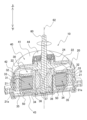
- FIG. 3 is a perspective cross-sectional view of the motor.
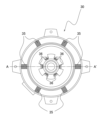
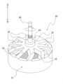
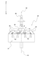
- FIG. 3 is a top view of the stator. It is a perspective view of a rotor. It is a side view of a rotor.
- FIG. 3 is a diagram showing air flow around a coil holding portion of a stator.
- FIG. 6 is a diagram showing the relationship between the wind speed of the air flow circulating around the coil holding portion of the stator and the inclination angle of the connecting portion.
- the refrigeration cycle device 200 is a device that uses a vapor compression refrigeration cycle to cool or heat a temperature-adjusted object.
- the refrigeration cycle device 200 is an air conditioner 200 that cools or heats air in an air-conditioned space as a temperature-adjusted object.
- the type of refrigeration cycle device 200 is not limited to the air conditioner 200, and may be a water heater, a floor heating device, a refrigeration device, or the like.
- FIG. 1 is an external view of the air conditioner 200.
- the air conditioner 200 mainly includes an indoor unit 210 that is attached to a wall or the like indoors, and an outdoor unit 220 that is installed outdoors.
- the indoor unit 210 and the outdoor unit 220 are connected to each other via a refrigerant pipe 230, thereby configuring a refrigerant circuit of the air conditioner 200.
- the air conditioner 200 performs cooling operation, heating operation, etc. in a space where the indoor unit 210 is installed.
- FIG. 2 is a cross-sectional view of the outdoor unit 220.
- the outdoor unit 220 mainly includes an air blower 100, a casing 102, a heat exchanger 104, a compressor 106, internal piping, and a control unit.
- the casing 102 houses the blower 100, the partition plate 103, the heat exchanger 104, the bell mouth 105, the compressor 106, and the like.
- the internal pipe is a part of the refrigerant circuit of the air conditioner 200, and is a pipe through which the refrigerant circulating in the refrigerant circuit flows.
- the control unit is a microcomputer including a CPU, memory, and the like. The control unit controls the motor 10 and the like of the blower device 100.
- the partition plate 103 partitions the space inside the casing 102 into a ventilation chamber 102a and a machine room 102b.
- the blowing device 100, the heat exchanger 104, and the bell mouth 105 are arranged in the blowing chamber 102a.
- the compressor 106 and the control unit are arranged in the machine room 102b.
- the compressor 106 compresses the refrigerant circulating in the refrigerant circuit of the air conditioner 200.
- the refrigerant compressed by the compressor 106 is sent to the heat exchanger 104 of the outdoor unit 220 during cooling operation, and is sent to the heat exchanger of the indoor unit 210 during heating operation.
- the heat exchanger 104 exchanges heat between the refrigerant and air.
- the heat exchanger 104 includes, for example, a heat exchanger tube that is folded back multiple times at both ends in the longitudinal direction, and fins attached to the heat exchanger tube.
- the heat transfer tube is a part of the refrigerant circuit of the air conditioner 200, and is a tube through which the refrigerant circulating in the refrigerant circuit flows.
- the heat exchanger 104 exchanges heat between the refrigerant flowing inside the heat transfer tube and the air passing through the fins.
- the heat exchanger 104 functions as a condenser (radiator) during cooling operation, and functions as an evaporator (heat absorber) during heating operation.
- the blower device 100 mainly includes a motor 10 and a fan 90.
- Fan 90 is driven by motor 10.
- Fan 90 is a propeller fan that sends air in a predetermined direction.
- Fan 90 generates airflow to facilitate heat exchange by heat exchanger 104. Due to the air flow generated by the rotation of the fan 90, air outside the casing 102 is sucked into the ventilation chamber 102a inside the casing 102. In this process, the air passes through the heat exchanger 104 to exchange heat with the refrigerant, and then passes through the bell mouth 105 and is discharged to the outside of the casing 102.
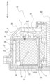
- FIG. 3 is a perspective sectional view of the motor 10. As shown in FIG. 3, the motor 10 mainly includes a rotor 20, a stator 30, a motor cover 40, and a shaft 60.
- the "axial direction” is the direction of the rotating shaft 62 of the rotor 20 (the vertical direction in FIG. 3).
- the “radial direction” is a radial direction centered on the rotating shaft 62 of the rotor 20.
- the “rotation direction” is the direction in which the rotor 20 rotates around the rotation shaft 62. As shown in FIG. 3, the rotor 20 rotates counterclockwise when viewed from above.
- the motor 10 is an outer rotor type motor.
- the stator 30 is arranged inside the rotor 20 in the radial direction.
- the stator 30 mainly includes a coil holding portion 34, a first through hole 35, and a second through hole 36.
- the stator 30 is integrally molded by resin molding.
- a bearing 37 is arranged between the inner circumference of the stator 30 and the shaft 60.
- Stator 30 supports shaft 60 via bearing 37.
- the coil holding section 34 includes a stator core 31, a coil 32, an insulator 33, and a connection plate 50.
- the stator core 31 is formed by laminating steel plates that are conductive soft magnetic materials.
- Stator core 31 has a plurality of teeth.
- the coil 32 is formed by winding a copper wire, an aluminum wire, or a copper-clad aluminum wire coated with an insulating material such as enamel resin around the teeth of the stator core 31.
- the insulator 33 is made of an insulating resin material. Insulator 33 is provided between stator core 31 and coil 32. The insulator 33 insulates between the stator core 31 and the coil 32 so that the current flowing through the coil 32 is not transmitted to the stator core 31.
- the wiring board 50 is connected to the lead wires at the start and end of winding of the coil 32.
- the wiring board 50 is connected to an external power source or the like via lead wires.
- the first through hole 35 is formed on the radially outer side of the coil holding part 34.
- the first through hole 35 passes through the stator 30 in the axial direction.
- FIG. 4 is a top view of the stator 30. In FIG. 4, the cross section in FIG. 3 is shown as cross section AA'. As shown in FIG. 4, the stator 30 has six first through holes 35.
- the first through hole 35 allows the airflow F2 generated by the rotation of the rotor 20 to pass therethrough. The air flow F2 will be described later.
- the second through hole 36 is formed inside the coil holding portion 34 in the radial direction.
- the second through hole 36 passes through the stator 30 in the axial direction.
- the stator 30 has six second through holes 36.
- the second through hole 36 passes through the air flow F4 generated by the rotation of the rotor 20.
- the air flow F4 will be described later.
- FIG. 5 is a perspective view of the rotor 20.
- the rotor 20 mainly includes a magnetic section 21, a plurality of connection sections 22, and a support section 24.
- the rotor 20 is integrally molded by resin molding.
- the rotor 20 is connected to the shaft 60 via the support portion 24 . Thereby, the rotor 20 rotates together with the shaft 60 around the rotation axis 62.
- the magnetic part 21 is cylindrical.
- the magnetic part 21 is arranged on the radially outer side of the stator 30.
- the magnetic part 21 has a plurality of magnets 21a.
- the plurality of magnets 21a are arranged in line in the rotation direction of the magnetic section 21.
- the connecting part 22 connects the shaft 60 and the magnetic part 21 via the supporting part 24.
- the number of connection parts 22 is ten.
- the number of connecting parts 22 is preferably 3 or more and 15 or less in order to facilitate resin molding of the connecting parts 22.
- FIG. 6 is a side view of the rotor 20.
- the first surface S1 on the front side of the connecting portion 22 in the rotational direction is the shaft 60 when viewed along the first direction (radial direction), which is the direction in which the connecting portion 22 extends from the shaft 60.
- the connection portion 22 is inclined in the opposite rotation direction with respect to a first plane P1 that includes the rotation axis 62 and extends in the first direction.
- connection portion 22 rotates, thereby creating a downward air flow F0.
- the inclination angle ⁇ between the first surface S1 and the first plane P1 is 10° or more and 30° or less.
- the motor cover 40 covers the rotor 20 and the stator 30.
- the motor cover 40 is made of resin material.
- the motor cover 40 is fixed to the casing 102 of the outdoor unit 220 via a vibration isolating member.
- the vibration isolating member is made of rubber or the like, and has a function of absorbing vibrations of the motor 10.
- the motor cover 40 mainly includes a first cover 41, a second cover 42, a third cover 43, and a fourth cover 44.
- the first cover 41 covers the upper surface of the rotor 20.
- a first flow path FC1 for an air flow F1 generated by rotation of the rotor 20 is formed between the stator 30, which is arranged radially inside the rotor 20, and the first cover 41.
- the first flow path FC1 will be described later.
- the second cover 42 covers the side surface (radially outer surface) of the rotor 20.
- a second flow path FC2 for air flow F2 generated by rotation of the rotor 20 is formed between the stator 30, which is disposed radially inside the rotor 20, and the second cover 42.
- the second flow path FC2 will be described later.
- the third cover 43 covers the bottom surface (lower surface) of the stator 30.
- a third flow path FC3 for air flow F3 generated by rotation of the rotor 20 is formed between the stator 30 and the third cover 43.
- the third flow path FC3 will be described later.
- the fourth cover 44 covers the upper part of the support part 24 of the rotor 20.
- the shaft 60 is a cylindrical member made of metal.
- the shaft 60 is connected to a fan 90 at an end opposite to the motor 10 in the axial direction.
- the stator 30 generates a magnetic field for rotating the rotor 20 by power supplied to the coil 32 from the outside via the connection plate 50.
- the rotor 20 is rotated by a magnetic field generated from the stator 30.
- a shaft 60 connected to the rotor 20 rotates around a rotation axis 62.
- the motor 10 supports the shaft 60 and transmits rotational force to the fan 90 via the shaft 60. Thereby, the motor 10 rotates the fan 90 around the rotating shaft 62.
- the temperature of the stator 30 (particularly, the coil holding part 34) increases by supplying electric power to the stator 30.
- FIG. 7 is a diagram showing that air flows F1 to F4 generated by the rotation of the rotor 20 circulate around the coil holding portion 34 of the stator 30. As shown in FIGS. 6 and 7, when the rotor 20 rotates around the rotating shaft 62, a downward air flow F0 is generated.
- a radially outward air flow F1 is generated.
- a first flow path FC1 for the air flow F1 is formed between the stator 30 and the first cover 41.
- a radially inward air flow F3 is generated.
- a third flow path FC3 for the air flow F3 is formed between the stator 30 and the third cover 43.
- the air flows F1 to F4 generated by the rotation of the rotor 20 passing through the first flow path FC1, the second flow path FC2, the first through hole 35, the third flow path FC3, and the second through hole 36 are as follows: It circulates around the coil holding part 34 of the stator 30. This suppresses a rise in temperature of the coil holding portion 34.
- FIG. 8 is a diagram showing the relationship between the wind speeds of air flows F1 to F4 circulating around the coil holding part 34 of the stator 30 and the inclination angle ⁇ of the connecting portion 22.
- the vertical axis of the graph shown in FIG. 8 is the wind speed of the air flow at observation point P shown in FIG.
- the magnitude of wind speed is expressed as a percentage.
- the horizontal axis of the graph shown in FIG. 8 is the angle of inclination ⁇ of the connecting portion 22.
- the inclination angle ⁇ is 10° or more and 30° or less increases by about 13% compared to the wind speed when the inclination angle ⁇ is 0°. Therefore, in order to increase the wind speed of the air flows F1 to F4 circulating around the coil holding part 34 of the stator 30 and further suppressing the temperature rise of the coil holding part 34 of the stator 30, the inclination angle ⁇ is , preferably 10° or more and 30° or less (particularly 10° or more and 25° or less).
- the problem with the conventional technology is that the size of the motor becomes large because a space is required to install the internal fan.
- the motor 10 of this embodiment includes a shaft 60, a rotor 20, and a stator 30.
- Rotor 20 is connected to shaft 60.
- the rotor 20 rotates together with the shaft 60 around a rotating shaft 62 .
- Stator 30 is arranged radially inside rotor 20 .
- the rotor 20 includes a magnetic section 21 and a plurality of connecting sections 22 .
- the magnetic part 21 has a cylindrical shape.
- the magnetic part 21 is arranged on the radially outer side of the stator 30.
- the connecting portion 22 connects the shaft 60 and the magnetic portion 21 .
- the first surface S1 on the front side in the rotation direction of the connecting portion 22 includes the rotation axis 62 of the shaft 60 and extends in the first direction when viewed along the first direction, which is the direction in which the connecting portion 22 extends from the shaft 60. It is inclined with respect to the first plane P1.
- the first surface S1 on the front side in the rotational direction of the connecting portion 22 is the rotation axis of the shaft 60 when viewed along the first direction, which is the direction in which the connecting portion 22 extends from the shaft 60. 62 and is inclined with respect to a first plane P1 extending in the first direction.
- the motor 10 generates air flows F1 to F4 within the motor without creating a space for an internal fan or the like by providing an inclination to the connecting portion 22 of the rotor 20 and blowing air into the motor 10.
- the temperature rise of the stator 30 can be suppressed.
- the inclination angle ⁇ between the first surface S1 and the first plane P1 is 10° or more and 30° or less.
- the motor 10 can generate stronger air flows F1 to F4 within the motor 10 by setting the inclination angle ⁇ to an appropriate angle.
- the motor 10 of this embodiment further includes a first cover 41.
- the first cover 41 covers the upper surface of the rotor 20.
- a first flow path FC1 for an air flow F1 generated by rotation of the rotor 20 is formed between the stator 30, which is arranged radially inside the rotor 20, and the first cover 41.
- the air flow F1 generated by the rotation of the rotor 20 flows through the first flow path FC1 adjacent to the stator 30, so that the temperature rise of the stator 30 can be suppressed.
- the motor 10 of this embodiment further includes a second cover 42.
- the second cover 42 covers the side surface of the rotor 20.
- a second flow path FC2 for air flow F2 generated by rotation of the rotor 20 is formed between the stator 30, which is disposed radially inside the rotor 20, and the second cover 42.
- the air flow F2 generated by the rotation of the rotor 20 flows through the second flow path FC2 adjacent to the stator 30, thereby suppressing a rise in temperature of the stator 30.
- the motor 10 of this embodiment further includes a third cover 43.
- the third cover 43 covers the bottom surface of the stator 30.
- a third flow path FC3 for air flow F3 generated by rotation of the rotor 20 is formed between the stator 30 and the third cover 43.
- the air flow F3 generated by the rotation of the rotor 20 flows through the third flow path FC3 adjacent to the stator 30, so that the temperature rise of the stator 30 can be suppressed.
- the stator 30 has the first through hole 35 on the radially outer side of the coil holding part 34 that holds the coil 32.
- the first through hole 35 allows the airflow F2 generated by the rotation of the rotor 20 to pass therethrough.
- the air flow F2 generated by the rotation of the rotor 20 flows through the first through hole 35 adjacent to the coil holding portion 34 of the stator 30, thereby suppressing the temperature rise of the stator 30. Can be done.
- the stator 30 has a second through hole 36 on the radially inner side of the coil holding portion 34 that holds the coil 32.
- the second through hole 36 passes through the air flow F4 generated by the rotation of the rotor 20.
- the air flow F4 generated by the rotation of the rotor 20 flows through the second through hole 36 adjacent to the coil holding portion 34 of the stator 30, thereby suppressing the temperature rise of the stator 30. Can be done.
- the air flows F1 to F4 passing through the first flow path FC1, the second flow path FC2, the first through hole 35, the third flow path FC3, and the second through hole 36 are connected to the coil holding portion. It circulates around 34.
- the air flows F1 to F4 generated by the rotation of the rotor 20 circulate around the coil holding portion 34 of the stator 30, thereby making it possible to further suppress the temperature rise of the stator 30. .
- connection parts 22 are 3 or more and 15 or less. As a result, in the motor 10, the connecting portion 22 can be easily molded with resin.
- the air blower 100 of this embodiment includes a motor 10 and a fan 90. Fan 90 is driven by motor 10.
- the air conditioner 200 of this embodiment includes an air blower 100.
- the motor 10 is used to drive the fan 90 in the air blower 100 of the outdoor unit 220, which employs an outer rotor type motor.
- the motor 10 may be used to drive a fan in an air blower of the indoor unit 210, an air blower of an air cleaner, an electric fan, etc., in which an outer rotor type motor is employed.
Landscapes
- Engineering & Computer Science (AREA)
- Power Engineering (AREA)
- Motor Or Generator Cooling System (AREA)
Abstract
Description
冷凍サイクル装置200は、蒸気圧縮式冷凍サイクルを利用して、温度調整対象を冷却したり、加熱したりする装置である。本実施形態では、冷凍サイクル装置200は、温度調整対象としての空調対象空間の空気を冷却したり加熱したりする空気調和装置200である。冷凍サイクル装置200の種類は、空気調和装置200に限定されるものではなく、給湯装置、床暖房装置、冷蔵装置等であってもよい。
図3は、モータ10の斜視断面図である。図3に示すように、モータ10は、主として、回転子20と、固定子30と、モータカバー40と、シャフト60と、を有する。
図3に示すように、固定子30は、主として、コイル保持部34と、第1貫通穴35と、第2貫通穴36と、を有する。固定子30は、樹脂モールド加工により一体成型される。固定子30の内周部とシャフト60との間には、ベアリング37が配置されている。固定子30は、ベアリング37を介して、シャフト60を支持している。
図5は、回転子20の斜視図である。図3及び図5に示すように、回転子20は、主として、磁気部21と、複数の接続部22と、支持部24と、を有する。回転子20は、樹脂モールド加工により一体成型される。回転子20は、支持部24を介して、シャフト60に接続される。これにより、回転子20は、シャフト60と共に回転軸62を中心に回転する。
図3に示すように、モータカバー40は、回転子20と、固定子30と、を覆っている。モータカバー40は、樹脂材料により形成されている。モータカバー40は、室外機220のケーシング102に対して防振部材を介して固定される。防振部材は、ゴム等で形成され、モータ10の振動を吸収する機能を有する。
シャフト60は、金属製の円柱状の部材である。シャフト60は、軸方向のモータ10とは反対側の端部において、ファン90と連結される。
図7は、回転子20の回転によって生じる空気流れF1~F4が、固定子30のコイル保持部34の周りを循環することを示す図である。図6及び図7に示すように、回転子20が回転軸62を中心に回転すると、下向きの空気流れF0が生じる。
ここでは、回転子20の回転数を一定としたときの、固定子30のコイル保持部34の周りを循環する空気流れF1~F4の風速と、接続部22の傾斜角θとの関係を、熱流体解析を用いて検証した。図8は、固定子30のコイル保持部34の周りを循環する空気流れF1~F4の風速と、接続部22の傾斜角θとの関係を示す図である。図8に示すグラフの縦軸は、図7に示す観測点Pにおける空気流れの風速である。風速の大きさは、百分率によって示している。図8に示すグラフの横軸は、接続部22の傾斜角θの角度である。
(5-1)
従来、回転子に内扇ファンを設け、モータ内に空気を吹き出すことにより、固定子の温度上昇を抑制する技術がある。
本実施形態のモータ10では、第1面S1は、第1平面P1に対して、接続部22の逆回転方向に傾斜している。その結果、モータ10は、モータ10内により強い空気流れF1~F4を生成することができる。
本実施形態のモータ10では、第1面S1と第1平面P1との傾斜角θは、10°以上30°以下である。その結果、モータ10は、傾斜角θを適切な角度に設定することにより、モータ10内により強い空気流れF1~F4を生成することができる。
本実施形態のモータ10は、第1カバー41をさらに備える。第1カバー41は、回転子20の上面を覆う。回転子20の径方向内側に配置される固定子30と、第1カバー41との間には、回転子20の回転によって生じる空気流れF1の第1流路FC1が形成される。
本実施形態のモータ10は、第2カバー42をさらに備える。第2カバー42は、回転子20の側面を覆う。回転子20の径方向内側に配置される固定子30と、第2カバー42との間には、回転子20の回転によって生じる空気流れF2の第2流路FC2が形成される。
本実施形態のモータ10は、第3カバー43をさらに備える。第3カバー43は、固定子30の底面を覆う。固定子30と第3カバー43との間には、回転子20の回転によって生じる空気流れF3の第3流路FC3が形成される。
本実施形態のモータ10では、固定子30は、コイル32を保持するコイル保持部34の径方向外側に、第1貫通穴35を有する。第1貫通穴35は、回転子20の回転によって生じる空気流れF2を通す。
本実施形態のモータ10では、固定子30は、コイル32を保持するコイル保持部34の径方向内側に、第2貫通穴36を有する。第2貫通穴36は、回転子20の回転によって生じる空気流れF4を通す。
本実施形態のモータ10では、第1流路FC1、第2流路FC2、第1貫通穴35、第3流路FC3、及び第2貫通穴36を通る空気流れF1~F4は、コイル保持部34の周りを循環する。その結果、モータ10は、回転子20の回転によって生じる空気流れF1~F4が、固定子30のコイル保持部34の周りを循環することにより、固定子30の温度上昇をより抑制することができる。
本実施形態のモータ10では、接続部22の数は、3個以上15個以下である。その結果、モータ10は、接続部22の樹脂モールド加工を容易に行うことができる。
本実施形態の送風装置100は、モータ10と、ファン90と、を備える。ファン90は、モータ10によって駆動される。
本実施形態の空気調和装置200は、送風装置100を備える。
(6-1)変形例1A
本実施形態では、モータ10は、アウターロータ型のモータが採用される、室外機220の送風装置100において、ファン90を駆動するために用いられた。しかし、モータ10は、アウターロータ型のモータが採用される、室内機210の送風装置、空気清浄機の送風装置、及び扇風機等において、ファンを駆動するために用いられてもよい。
以上、本開示の実施形態を説明したが、特許請求の範囲に記載された本開示の趣旨及び範囲から逸脱することなく、形態や詳細の多様な変更が可能なことが理解されるであろう。
20 回転子
21 磁気部
22 接続部
30 固定子
32 コイル
34 コイル保持部
35,36 第1貫通穴,第2貫通穴
41~43 第1カバー~第3カバー
60 シャフト
62 回転軸
90 ファン
100 送風装置
200 空気調和装置(冷凍サイクル装置)
F1~F4 空気流れ
FC1~FC3 第1流路~第3流路
S1 第1面
P1 第1平面
θ 傾斜角
Claims (12)
- シャフト(60)と、
前記シャフトに接続され、前記シャフトと共に回転軸(62)を中心に回転する回転子(20)と、
前記回転子の径方向内側に配置される固定子(30)と、
を備え、
前記回転子は、前記固定子の径方向外側に配置される円筒状の磁気部(21)と、前記シャフトと前記磁気部とを接続する複数の接続部(22)と、を有し、
前記接続部の回転方向の前側の第1面(S1)は、前記シャフトから前記接続部が延びる方向である第1方向に沿って見たときに、前記シャフトの前記回転軸を含み前記第1方向に延びる第1平面(P1)に対して傾斜している、
モータ(10)。 - 前記第1面は、前記第1平面に対して、前記接続部の逆回転方向に傾斜している、
請求項1に記載のモータ(10)。 - 前記第1面と前記第1平面との傾斜角(θ)は、10°以上30°以下である、
請求項1又は2に記載のモータ(10)。 - 前記回転子の上面を覆う第1カバー(41)、
をさらに備え、
前記回転子の径方向内側に配置される前記固定子と、前記第1カバーとの間には、前記回転子の回転によって生じる空気流れ(F1)の第1流路(FC1)が形成される、
請求項1から3のいずれか1つに記載のモータ(10)。 - 前記回転子の側面を覆う第2カバー(42)、
をさらに備え、
前記回転子の径方向内側に配置される前記固定子と、前記第2カバーとの間には、前記回転子の回転によって生じる空気流れ(F2)の第2流路(FC2)が形成される、
請求項1から4のいずれか1つに記載のモータ(10)。 - 前記固定子の底面を覆う第3カバー(43)、
をさらに備え、
前記固定子と前記第3カバーとの間には、前記回転子の回転によって生じる空気流れ(F3)の第3流路(FC3)が形成される、
請求項1から5のいずれか1つに記載のモータ(10)。 - 前記固定子は、コイル(32)を保持するコイル保持部(34)の径方向外側に、前記回転子の回転によって生じる空気流れ(F2)を通す第1貫通穴(35)を有する、
請求項1から6のいずれか1つに記載のモータ(10)。 - 前記固定子は、コイル(32)を保持するコイル保持部(34)の径方向内側に、前記回転子の回転によって生じる空気流れ(F4)を通す第2貫通穴(36)を有する、
請求項1から7のいずれか1つに記載のモータ(10)。 - 前記回転子の上面を覆う第1カバー(41)と、
前記回転子の側面を覆う第2カバー(42)と、
前記固定子の底面を覆う第3カバー(43)と、
をさらに備え、
前記回転子の径方向内側に配置される前記固定子と、前記第1カバーとの間には、前記回転子の回転によって生じる空気流れ(F1)の第1流路(FC1)が形成され、
前記固定子と、前記第2カバーとの間には、前記回転子の回転によって生じる空気流れ(F2)の第2流路(FC2)が形成され、
前記固定子と前記第3カバーとの間には、前記回転子の回転によって生じる空気流れ(F3)の第3流路(FC3)が形成され、
前記固定子は、
コイル(32)を保持するコイル保持部(34)の径方向外側に、前記回転子の回転によって生じる空気流れ(F2)を通す第1貫通穴(35)を有し、
前記コイル保持部の径方向内側に、前記回転子の回転によって生じる空気流れ(F4)を通す第2貫通穴(36)を有し、
前記第1流路、前記第2流路、前記第1貫通穴、前記第3流路、及び前記第2貫通穴を通る空気流れ(F1~F4)は、前記コイル保持部の周りを循環する、
請求項1又は2に記載のモータ(10)。 - 前記接続部の数は、3個以上15個以下である、
請求項1から9のいずれか1つに記載のモータ(10)。 - 請求項1から10のいずれか1つに記載のモータ(10)と、
前記モータによって駆動されるファン(90)と、
を備える、
送風装置(100)。 - 請求項11に記載の送風装置(100)、
を備える、
冷凍サイクル装置(200)。
Priority Applications (1)
| Application Number | Priority Date | Filing Date | Title |
|---|---|---|---|
| CN202380052357.1A CN119497949A (zh) | 2022-07-21 | 2023-07-14 | 马达、送风装置以及制冷循环装置 |
Applications Claiming Priority (2)
| Application Number | Priority Date | Filing Date | Title |
|---|---|---|---|
| JP2022-116261 | 2022-07-21 | ||
| JP2022116261A JP7406137B1 (ja) | 2022-07-21 | 2022-07-21 | モータ、送風装置、及び冷凍サイクル装置 |
Publications (1)
| Publication Number | Publication Date |
|---|---|
| WO2024019016A1 true WO2024019016A1 (ja) | 2024-01-25 |
Family
ID=89307926
Family Applications (1)
| Application Number | Title | Priority Date | Filing Date |
|---|---|---|---|
| PCT/JP2023/026087 Ceased WO2024019016A1 (ja) | 2022-07-21 | 2023-07-14 | モータ、送風装置、及び冷凍サイクル装置 |
Country Status (3)
| Country | Link |
|---|---|
| JP (1) | JP7406137B1 (ja) |
| CN (1) | CN119497949A (ja) |
| WO (1) | WO2024019016A1 (ja) |
Citations (9)
| Publication number | Priority date | Publication date | Assignee | Title |
|---|---|---|---|---|
| JP2003088014A (ja) * | 2001-09-07 | 2003-03-20 | Asmo Co Ltd | 回転電機用電機子及び回転電機 |
| JP2003143809A (ja) * | 2001-10-31 | 2003-05-16 | Toshiba Transport Eng Inc | 車両用全閉外扇形電動機 |
| JP2013150441A (ja) * | 2012-01-19 | 2013-08-01 | Mitsuba Corp | アウターロータ型ブラシレスモータ |
| JP2017204980A (ja) * | 2016-05-13 | 2017-11-16 | 本田技研工業株式会社 | 回転電機およびその製造方法 |
| JP2018038179A (ja) * | 2016-08-31 | 2018-03-08 | 日本電産株式会社 | モータ |
| JP2018117505A (ja) * | 2017-01-20 | 2018-07-26 | 日本電産株式会社 | モータ及びそれを備えた送風装置 |
| CN207853677U (zh) * | 2018-03-09 | 2018-09-11 | 上海惠深工具科技有限公司 | 自冷却外转子电机 |
| CN209930055U (zh) * | 2019-04-30 | 2020-01-10 | 广东万瑞机电科技有限公司 | 一种带风叶的电机外转子构造 |
| WO2020145219A1 (ja) * | 2019-01-08 | 2020-07-16 | 日本電産株式会社 | モータ、回転翼装置 |
-
2022
- 2022-07-21 JP JP2022116261A patent/JP7406137B1/ja active Active
-
2023
- 2023-07-14 WO PCT/JP2023/026087 patent/WO2024019016A1/ja not_active Ceased
- 2023-07-14 CN CN202380052357.1A patent/CN119497949A/zh active Pending
Patent Citations (9)
| Publication number | Priority date | Publication date | Assignee | Title |
|---|---|---|---|---|
| JP2003088014A (ja) * | 2001-09-07 | 2003-03-20 | Asmo Co Ltd | 回転電機用電機子及び回転電機 |
| JP2003143809A (ja) * | 2001-10-31 | 2003-05-16 | Toshiba Transport Eng Inc | 車両用全閉外扇形電動機 |
| JP2013150441A (ja) * | 2012-01-19 | 2013-08-01 | Mitsuba Corp | アウターロータ型ブラシレスモータ |
| JP2017204980A (ja) * | 2016-05-13 | 2017-11-16 | 本田技研工業株式会社 | 回転電機およびその製造方法 |
| JP2018038179A (ja) * | 2016-08-31 | 2018-03-08 | 日本電産株式会社 | モータ |
| JP2018117505A (ja) * | 2017-01-20 | 2018-07-26 | 日本電産株式会社 | モータ及びそれを備えた送風装置 |
| CN207853677U (zh) * | 2018-03-09 | 2018-09-11 | 上海惠深工具科技有限公司 | 自冷却外转子电机 |
| WO2020145219A1 (ja) * | 2019-01-08 | 2020-07-16 | 日本電産株式会社 | モータ、回転翼装置 |
| CN209930055U (zh) * | 2019-04-30 | 2020-01-10 | 广东万瑞机电科技有限公司 | 一种带风叶的电机外转子构造 |
Also Published As
| Publication number | Publication date |
|---|---|
| JP2024013859A (ja) | 2024-02-01 |
| JP7406137B1 (ja) | 2023-12-27 |
| CN119497949A (zh) | 2025-02-21 |
Similar Documents
| Publication | Publication Date | Title |
|---|---|---|
| CN100507376C (zh) | 用于空调设备的前吸入/排出型室外机及其风扇 | |
| CN101189478B (zh) | 用于分体式空调的室外单元 | |
| JP7406137B1 (ja) | モータ、送風装置、及び冷凍サイクル装置 | |
| EP3401546A1 (en) | Axial fan assembly and motor home air-conditioner using same | |
| JP6993602B1 (ja) | モータ、送風機、および、空気調和装置 | |
| US11605992B2 (en) | Motor, motor assembly, and air conditioner | |
| JP2024130963A (ja) | アキシャルギャップ型電動発電機、送風装置、空気調和装置、及び冷凍装置 | |
| US20070290560A1 (en) | Motor and Electric Apparatus Using the Same Motor | |
| CN118613994A (zh) | 电动机和空调机 | |
| CN101675303B (zh) | 空调 | |
| CN1900616B (zh) | 送风装置 | |
| JP6896066B2 (ja) | 電動機、送風機、室外機、及び、空気調和機 | |
| JP2016044868A (ja) | 室外機及びこの室外機を備えた空気調和機 | |
| JPH07336930A (ja) | ファンモータ | |
| JP3813356B2 (ja) | 遠心式送風手段を用いた熱交換器 | |
| KR100690145B1 (ko) | 공기조화기용 실외기의 송풍장치 설치구조 | |
| JP2024012997A (ja) | 電気機器 | |
| JP2026061332A (ja) | 送風機、及び冷凍装置 | |
| WO2024089836A1 (ja) | 電動機、ファン、及び空気調和機 | |
| CN121124451A (zh) | 高效散热型汽车发电机定子绕组结构 | |
| JP2022062616A (ja) | モータ、送風機、および、空気調和装置 | |
| JP2006158191A (ja) | モータ及びそれを搭載した電気機器 | |
| WO2006030696A1 (ja) | 冷凍装置の室外機 |
Legal Events
| Date | Code | Title | Description |
|---|---|---|---|
| 121 | Ep: the epo has been informed by wipo that ep was designated in this application |
Ref document number: 23842939 Country of ref document: EP Kind code of ref document: A1 |
|
| WWE | Wipo information: entry into national phase |
Ref document number: 202380052357.1 Country of ref document: CN |
|
| WWP | Wipo information: published in national office |
Ref document number: 202380052357.1 Country of ref document: CN |
|
| NENP | Non-entry into the national phase |
Ref country code: DE |
|
| 122 | Ep: pct application non-entry in european phase |
Ref document number: 23842939 Country of ref document: EP Kind code of ref document: A1 |