WO2024018917A1 - 光ファイバ母材の製造装置、製造方法、光ファイバ母材および光ファイバ - Google Patents
光ファイバ母材の製造装置、製造方法、光ファイバ母材および光ファイバ Download PDFInfo
- Publication number
- WO2024018917A1 WO2024018917A1 PCT/JP2023/025183 JP2023025183W WO2024018917A1 WO 2024018917 A1 WO2024018917 A1 WO 2024018917A1 JP 2023025183 W JP2023025183 W JP 2023025183W WO 2024018917 A1 WO2024018917 A1 WO 2024018917A1
- Authority
- WO
- WIPO (PCT)
- Prior art keywords
- optical fiber
- burner
- fiber preform
- core rod
- flame
- Prior art date
- Legal status (The legal status is an assumption and is not a legal conclusion. Google has not performed a legal analysis and makes no representation as to the accuracy of the status listed.)
- Ceased
Links
Images








Classifications
-
- C—CHEMISTRY; METALLURGY
- C03—GLASS; MINERAL OR SLAG WOOL
- C03B—MANUFACTURE, SHAPING, OR SUPPLEMENTARY PROCESSES
- C03B37/00—Manufacture or treatment of flakes, fibres, or filaments from softened glass, minerals, or slags
- C03B37/01—Manufacture of glass fibres or filaments
- C03B37/012—Manufacture of preforms for drawing fibres or filaments
- C03B37/01205—Manufacture of preforms for drawing fibres or filaments starting from tubes, rods, fibres or filaments
- C03B37/01225—Means for changing or stabilising the shape, e.g. diameter, of tubes or rods in general, e.g. collapsing
- C03B37/01257—Heating devices therefor
-
- C—CHEMISTRY; METALLURGY
- C03—GLASS; MINERAL OR SLAG WOOL
- C03B—MANUFACTURE, SHAPING, OR SUPPLEMENTARY PROCESSES
- C03B19/00—Other methods of shaping glass
- C03B19/10—Forming beads
- C03B19/1005—Forming solid beads
- C03B19/106—Forming solid beads by chemical vapour deposition; by liquid phase reaction
-
- C—CHEMISTRY; METALLURGY
- C03—GLASS; MINERAL OR SLAG WOOL
- C03B—MANUFACTURE, SHAPING, OR SUPPLEMENTARY PROCESSES
- C03B37/00—Manufacture or treatment of flakes, fibres, or filaments from softened glass, minerals, or slags
- C03B37/01—Manufacture of glass fibres or filaments
- C03B37/012—Manufacture of preforms for drawing fibres or filaments
- C03B37/01205—Manufacture of preforms for drawing fibres or filaments starting from tubes, rods, fibres or filaments
- C03B37/01208—Manufacture of preforms for drawing fibres or filaments starting from tubes, rods, fibres or filaments for making preforms of microstructured, photonic crystal or holey optical fibres
-
- C—CHEMISTRY; METALLURGY
- C03—GLASS; MINERAL OR SLAG WOOL
- C03B—MANUFACTURE, SHAPING, OR SUPPLEMENTARY PROCESSES
- C03B37/00—Manufacture or treatment of flakes, fibres, or filaments from softened glass, minerals, or slags
- C03B37/01—Manufacture of glass fibres or filaments
- C03B37/012—Manufacture of preforms for drawing fibres or filaments
- C03B37/01205—Manufacture of preforms for drawing fibres or filaments starting from tubes, rods, fibres or filaments
- C03B37/01225—Means for changing or stabilising the shape, e.g. diameter, of tubes or rods in general, e.g. collapsing
- C03B37/0126—Means for supporting, rotating, translating the rod, tube or preform
-
- C—CHEMISTRY; METALLURGY
- C03—GLASS; MINERAL OR SLAG WOOL
- C03B—MANUFACTURE, SHAPING, OR SUPPLEMENTARY PROCESSES
- C03B37/00—Manufacture or treatment of flakes, fibres, or filaments from softened glass, minerals, or slags
- C03B37/01—Manufacture of glass fibres or filaments
- C03B37/012—Manufacture of preforms for drawing fibres or filaments
- C03B37/014—Manufacture of preforms for drawing fibres or filaments made entirely or partially by chemical means, e.g. vapour phase deposition of bulk porous glass either by outside vapour deposition [OVD], or by outside vapour phase oxidation [OVPO] or by vapour axial deposition [VAD]
- C03B37/01413—Reactant delivery systems
- C03B37/0142—Reactant deposition burners
-
- C—CHEMISTRY; METALLURGY
- C03—GLASS; MINERAL OR SLAG WOOL
- C03B—MANUFACTURE, SHAPING, OR SUPPLEMENTARY PROCESSES
- C03B37/00—Manufacture or treatment of flakes, fibres, or filaments from softened glass, minerals, or slags
- C03B37/01—Manufacture of glass fibres or filaments
- C03B37/012—Manufacture of preforms for drawing fibres or filaments
- C03B37/014—Manufacture of preforms for drawing fibres or filaments made entirely or partially by chemical means, e.g. vapour phase deposition of bulk porous glass either by outside vapour deposition [OVD], or by outside vapour phase oxidation [OVPO] or by vapour axial deposition [VAD]
- C03B37/018—Manufacture of preforms for drawing fibres or filaments made entirely or partially by chemical means, e.g. vapour phase deposition of bulk porous glass either by outside vapour deposition [OVD], or by outside vapour phase oxidation [OVPO] or by vapour axial deposition [VAD] by glass deposition on a glass substrate, e.g. by inside-, modified-, plasma- or plasma modified- chemical vapour deposition [ICVD, MCVD, PCVD, PMCVD], i.e. by thin layer coating on the inside or outside of a glass tube or on a glass rod
-
- C—CHEMISTRY; METALLURGY
- C03—GLASS; MINERAL OR SLAG WOOL
- C03B—MANUFACTURE, SHAPING, OR SUPPLEMENTARY PROCESSES
- C03B37/00—Manufacture or treatment of flakes, fibres, or filaments from softened glass, minerals, or slags
- C03B37/01—Manufacture of glass fibres or filaments
- C03B37/02—Manufacture of glass fibres or filaments by drawing or extruding, e.g. direct drawing of molten glass from nozzles; Cooling fins therefor
- C03B37/025—Manufacture of glass fibres or filaments by drawing or extruding, e.g. direct drawing of molten glass from nozzles; Cooling fins therefor from reheated softened tubes, rods, fibres or filaments, e.g. drawing fibres from preforms
- C03B37/027—Fibres composed of different sorts of glass, e.g. glass optical fibres
-
- C—CHEMISTRY; METALLURGY
- C03—GLASS; MINERAL OR SLAG WOOL
- C03B—MANUFACTURE, SHAPING, OR SUPPLEMENTARY PROCESSES
- C03B2203/00—Fibre product details, e.g. structure, shape
- C03B2203/42—Photonic crystal fibres, e.g. fibres using the photonic bandgap PBG effect, microstructured or holey optical fibres
-
- C—CHEMISTRY; METALLURGY
- C03—GLASS; MINERAL OR SLAG WOOL
- C03B—MANUFACTURE, SHAPING, OR SUPPLEMENTARY PROCESSES
- C03B2207/00—Glass deposition burners
- C03B2207/50—Multiple burner arrangements
-
- C—CHEMISTRY; METALLURGY
- C03—GLASS; MINERAL OR SLAG WOOL
- C03B—MANUFACTURE, SHAPING, OR SUPPLEMENTARY PROCESSES
- C03B2207/00—Glass deposition burners
- C03B2207/50—Multiple burner arrangements
- C03B2207/52—Linear array of like burners
-
- C—CHEMISTRY; METALLURGY
- C03—GLASS; MINERAL OR SLAG WOOL
- C03B—MANUFACTURE, SHAPING, OR SUPPLEMENTARY PROCESSES
- C03B2207/00—Glass deposition burners
- C03B2207/60—Relationship between burner and deposit, e.g. position
- C03B2207/64—Angle
-
- C—CHEMISTRY; METALLURGY
- C03—GLASS; MINERAL OR SLAG WOOL
- C03B—MANUFACTURE, SHAPING, OR SUPPLEMENTARY PROCESSES
- C03B2207/00—Glass deposition burners
- C03B2207/60—Relationship between burner and deposit, e.g. position
- C03B2207/66—Relative motion
-
- C—CHEMISTRY; METALLURGY
- C03—GLASS; MINERAL OR SLAG WOOL
- C03B—MANUFACTURE, SHAPING, OR SUPPLEMENTARY PROCESSES
- C03B2207/00—Glass deposition burners
- C03B2207/70—Control measures
Definitions
- the present invention relates to an optical fiber preform manufacturing apparatus, a manufacturing method, an optical fiber preform, and an optical fiber.
- the method for manufacturing an optical fiber preform described in Patent Document 1 is based on the method of manufacturing an optical fiber preform by regulating the ratio of the moving speed of a burner for depositing glass fine particles onto a core rod, which is a starting material for an optical fiber preform, and the rotational speed of the core rod.
- the method includes a step of reducing unevenness on the surface of the fiber base material.
- Patent Document 1 only defines the relationship between the moving speed of one burner and the rotational speed of the core rod.
- the flame trajectories of the plurality of burners overlap each other, causing unevenness on the surface of the optical fiber preform.
- the present invention has been made in view of the above problems, and an object of the present invention is to reduce unevenness on the surface of an optical fiber preform when a plurality of burners are used.
- N (N is an integer of 2 or more) and a raw material ejection port
- the burner array reciprocates around the core rod in the longitudinal direction at a speed v, and forms a porous glass portion on the outer periphery of the core rod
- the number of rotations (L+x) of the core rod when the burner array moves by the distance d in the longitudinal direction When the L is an arbitrary natural number and the offset x is greater than -0.5 and less than +0.5, the absolute value of the offset x is An apparatus for manufacturing an optical fiber preform is provided.
- an optical fiber preform manufacturing apparatus that can reduce unevenness on the surface of an optical fiber preform.
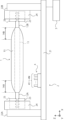
- FIG. 1 is a side view of a deposition apparatus used for manufacturing an optical fiber preform in a first embodiment of the present invention.
- FIG. 2 is a block diagram of a control device that controls the deposition apparatus in the first embodiment of the present invention.
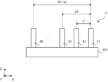
- FIG. 3 is a side view of the burner array in the first embodiment of the invention.
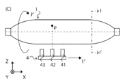
- FIG. 4A is a schematic diagram of the operation of the burner array in the first embodiment of the present invention.
- FIG. 4B is a schematic diagram of the operation of the burner array in the first embodiment of the invention.
- FIG. 4C is a schematic diagram of the operation of the burner array in the first embodiment of the invention.
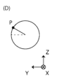
- FIG. 4D is a schematic diagram of the operation of the burner array in the first embodiment of the invention.
- FIG. 4A is a schematic diagram of the operation of the burner array in the first embodiment of the present invention.
- FIG. 4B is a schematic diagram of the operation of the burner array in the first embodiment of the invention.
- FIG. 4C is a schematic diagram of
- FIG. 4E is a schematic diagram of the operation of the burner array in the first embodiment of the invention.
- FIG. 4F is a schematic diagram of the operation of the burner array in the first embodiment of the invention.
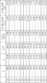
- FIG. 5 is a diagram showing the distance of the trajectory of the burner flame with respect to the manufacturing conditions of the optical fiber preform in the first embodiment of the present invention.
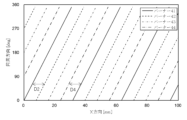
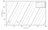
- FIG. 6A is a developed view of the locus of the burner array formed on the side of the optical fiber preform in the first embodiment of the present invention.
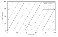
- FIG. 6B is a developed view of the locus of the burner array formed on the side of the optical fiber preform in the first embodiment of the present invention.
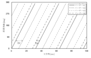
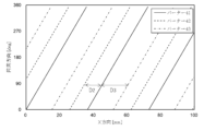
- FIG. 6C is a developed view of the locus of the burner array formed on the side of the optical fiber preform in the first embodiment of the present invention.
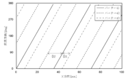
- FIG. 6D is a developed view of the locus of the burner array formed on the side of the optical fiber preform in the first embodiment of the present invention.
- FIG. 7 is a diagram showing the distance of the trajectory of the burner flame with respect to the manufacturing conditions of the optical fiber preform in the first embodiment of the present invention.
- FIG. 8A is a developed view of the locus of the burner array formed on the side of the optical fiber preform in the first embodiment of the present invention.
- FIG. 8B is a developed view of the locus of the burner array formed on the side of the optical fiber preform in the first embodiment of the present invention.
- FIG. 8C is a developed view of the locus of the burner array formed on the side of the optical fiber preform in the first embodiment of the present invention.
- FIG. 8A is a developed view of the locus of the burner array formed on the side of the optical fiber preform in the first embodiment of the present invention.
- FIG. 8B is a developed view of the locus of the burner array formed on the side of the optical
- FIG. 8D is a developed view of the locus of the burner array formed on the side of the optical fiber preform in the first embodiment of the present invention.
- FIG. 9 is a flowchart of a method for manufacturing an optical fiber preform and an optical fiber in the first embodiment of the present invention.
- FIG. 11A is a diagram showing a variation in the outer diameter of the optical fiber preform of Example 1 in the first embodiment of the present invention.
- FIG. 11B is a diagram showing a variation in the outer diameter of the optical fiber preform of Example 2 in the first embodiment of the present invention.
- FIG. 11C is a diagram showing a variation in the outer diameter of the optical fiber preform of a comparative example in the first embodiment of the present invention.
- FIG. 1 is a side view of a deposition apparatus used for manufacturing an optical fiber preform in this embodiment.
- the core rod of the optical fiber preform 1 includes a core portion 11 and support portions 12A and 12B.
- the core portion 11 is a starting material for the optical fiber preform 1 and is made of quartz glass or the like.
- the core portion 11 may be formed by heating and stretching a rod having a core and a cladding layer formed around the outer periphery of the core.
- the core portion 11 has a substantially cylindrical shape, and may have a length of 4000 mm and a diameter of 60 mm, for example. Glass particles are deposited on the outer periphery of the side portion of the core portion 11 in a deposition process described later, thereby forming the optical fiber preform 1.
- the support parts 12A and 12B are support rods, and the support parts 12A and 12B are provided at both ends of the core part 11, respectively.
- the support parts 12A and 12B are used to support the core part 11 in the glass particle deposition process and sintering process.
- the support parts 12A and 12B are made of quartz or the like like the core part 11.
- the support portions 12A, 12B have a substantially cylindrical shape, and may have a length of 1000 mm and a diameter of 90 mm, for example. The length and diameter of the support portions 12A and 12B may be changed as appropriate depending on the length or diameter of the core portion 11, the thickness on which the glass particles are deposited, and the like.
- the support parts 12A and 12B are joined to the core part 11 so that the support axes of the support parts 12A and 12B and the core axis of the core part 11 are located on substantially the same line.
- the support parts 12A and 12B are welded to the core part 11 using an oxyhydrogen burner or the like.
- the welding method is not limited to this, and an electric furnace or the like may be used for welding and joining.
- the porous glass part 13 is a layer of glass fine particles deposited on the core part 11.
- the porous glass portion 13 is deposited on the core portion 11 by the deposition device 2 .
- the method of depositing the porous glass portion 13 may be, for example, a VAD (Vapor Phase Axial Deposition) method, an OVD (Outside Vapor Deposition) method, or the like.
- the OVD method is a method in which the core portion 11 is held at both ends and glass fine particles are deposited horizontally on the sides of the core portion 11 .
- the porous glass portion 13 is deposited by the OVD method using a horizontal deposition apparatus.
- the porous glass portion 13 includes tapered portions 14A and 14B.
- the tapered portions 14A and 14B are formed with a predetermined length in the X direction.
- the predetermined length corresponds to the distance in the X direction from a burner at one end to a burner at the other end of a burner array to be described later.
- the deposition apparatus 2 includes a base 21, support parts 22A and 22B, a grip part 23, a stress applying part 24, a control device 3, and a burner array 4.
- the base 21 is a member that becomes the base of the deposition apparatus 2, and has a substantially rectangular parallelepiped shape.
- the base 21 is installed substantially horizontally with respect to the ground plane.
- the base 21 includes a rail extending in the longitudinal direction of the base 21 and provided below the core portion 11, and the support portions 22A, 22B and the burner array 4 are movable along the rail. In this embodiment, a configuration including one rail and one burner array 4 is described, but a configuration including a plurality of rails and a plurality of burner arrays 4 may be used.
- the plurality of rails be provided at a predetermined angle in the circumferential direction of the core portion 11.
- the three rails are provided in the circumferential direction at an angle of 120 degrees to each other, and the burner array 4 is installed on each rail.
- the longitudinal direction of the base 21 is the X direction
- the lateral direction of the base 21 is the Y direction
- the vertical direction of the base 21 is the Z direction.
- the support parts 22A and 22B have a columnar shape, are opposed to each other, and are provided on the upper part of the base 21. That is, the support portion 22A is provided at one end of the base 21, and the support portion 22B is provided at the other end of the base 21. At least one of the supports 22A and 22B is movable on a rail laid on the base 21.
- the support parts 22A, 22B are equipped with a rotary motor, a transmission, etc. that rotate the core part 11 via the support parts 12A, 12B.
- the gripping part 23 and the stress applying part 24 constitute a chuck, and are provided on the supporting parts 22A and 22B, respectively.
- the grip part 23 is made of metal such as SUS (Steel Use Stainless) or heat-resistant fluororesin, and includes a plurality of claws that can be brought close to each other or separated from each other.
- a gripping hole that can grip the support parts 12A and 12B is formed in the center of the plurality of claws.
- the stress applying part 24 is provided around the grip part 23 and is capable of applying stress to the grip part 23.
- the stress applying section 24 applies stress to the gripping section 23
- the plurality of claws move closer to each other, and the diameter of the gripping hole becomes smaller.
- the support parts 12A and 12B inserted into the grip holes are gripped by the grip part 23.
- the control device 3 is communicably connected to the deposition device 2 and controls the operation of the deposition device 2 and the burner array 4.
- the control device 3 controls the rotational direction and rotational speed when the deposition device 2 rotationally drives the core section 11, the magnitude of the stress of the stress applying section 24, the moving direction and moving speed of the burner array 4, the moving range in the X direction, etc. can be controlled.
- the burner array 4 includes a plurality of burners 41 to 4N and is installed on the rail of the base 21.
- the burner array 4 can move on the rail in the X direction and deposit glass particles on the core part 11 that rotates around the core axis.
- the burner 41 is a burner that sprays glass particles onto the core portion 11, and is, for example, a burner that uses gas mainly composed of hydrocarbons (methane) and oxygen or oxyhydrogen as fuel.
- the burner 41 includes a nozzle for supplying combustible gas, a nozzle for supplying combustion auxiliary gas, a nozzle (raw material spout) for supplying glass raw material, and the like.
- the combustible gas may be a gas containing hydrogen or a hydrocarbon as a main component, and the combustible gas may be oxygen or the like.
- the glass raw material may be, for example, a cyclic siloxane, SiCl4 , etc.
- the burner 41 injects glass raw materials into a flame, and generates glass particles through oxidation/pyrolysis reactions, flame hydrolysis reactions, and the like.
- the plurality of burners 41 to 4N operate as one. In this way, the porous glass portion 13 is deposited on the outer periphery of the core portion 11, and the optical fiber preform 1 is formed.
- FIG. 2 is a block diagram of a control device that controls the deposition apparatus in this embodiment.
- the control device 3 includes a CPU (Central Processing Unit) 301, a ROM (Read Only Memory) 302, a RAM (Random Access Memory) 303, a storage device 304, a display 305, a touch sensor 306, and an input device 3. 07, communication I/F308, sensor It includes an I/F 309 and a bus 310. Each part is interconnected via a bus 310.
- the CPU 301 controls each part of the deposition device 2 and the burner array 4 using an application program.
- the ROM 302 is composed of a non-volatile memory and stores an application program for controlling each part of the deposition apparatus 2 and the burner array 4.
- RAM 303 provides a memory area necessary for the operation of CPU 301.
- the storage device 304 is composed of a hard disk, a semiconductor memory, and the like.
- the display 305 includes, for example, a liquid crystal display, an organic light emitting diode (OLED) display, a light emitting diode (LED) display, or the like.
- a touch sensor 306 is arranged on the surface of the display 305. Touch sensor 306 includes a capacitive or resistive detection circuit.
- the input device 307 is a user I/F, and may be, for example, a keyboard, a mouse, or the like.
- the communication I/F 308 is a communication unit that transmits and receives data, and connects the control device 3 and the deposition device 2 in a communicable manner. Communication between the control device 3 and the deposition device 2 via the communication I/F 308 may be either wired communication or wireless communication.
- Wireless communication methods include, for example, 3rd generation mobile communication, LTE (Long Term Evolution), 4th generation mobile communication, 5th generation mobile communication, short-range wireless communication such as Bluetooth (registered trademark), Wi-Fi, etc. It may be wireless communication using a wireless LAN connection, etc.
- the sensor I/F 309 acquires various data from sensors included in the deposition apparatus 2 and stores it in the storage device 304 or the like.
- Various data include, for example, the temperature around the optical fiber preform 1, the surrounding humidity, the mass of the optical fiber preform 1, the surface temperature, the surface roughness, the rotation direction, the rotation speed, the acceleration, the rotation angle, and the porous glass. It may be the amount of accumulation in the portion 13, the position of the burner array 4, the temperature of the flames of the burners 41 to 4N, etc.
- the control device 3 receives the control parameters of the deposition device 2 and the control parameters of the burner array 4 through an operator's operation, and controls the deposition device 2 and the burner array 4.
- the control device 3 also receives information from a sensor (not shown) provided in the deposition device 2 via the sensor I/F 309, and receives information such as the rotation direction, rotation speed, and rotation angle of the rotating optical fiber preform 1. , the position of the burner array 4, etc. can be calculated and reflected in the control of the deposition device 2 and the burner array 4.
- FIG. 3 is a side view of the burner array in this embodiment.
- the burner array 4 includes a burner stand 401 and N burners 41 to 4N.
- the number N of burners is an integer of 2 or more.
- the burner stand 401 is movable on the rails of the base 21 in the X direction.
- the burners 41 to 4N are installed in a substantially straight line above the burner stand 401.
- Burner 41 and burner 42 are installed with a distance d between them, and burner 41 and burner 43 are installed with a distance of 2d between them. That is, the burners 41 to 4N are installed in a substantially straight line above the burner stand 401, and a distance d is provided between adjacent burners.
- the distance from burner 41 to burner 4N in the X direction is (N-1)d.
- the number N of burners and the distance d can be adjusted depending on the length of the optical fiber preform 1, the desired deposition amount of the porous glass portion 13, the desired length of the tapered portions 14A and 14B, and the like.
- the temperature of the flame in the burner array 4 the amount of combustible gas and auxiliary gas supplied, the amount of glass raw material supplied, the nozzle and the light
- the angle formed with the fiber base material 1, etc. can be controlled independently for each burner array 4.
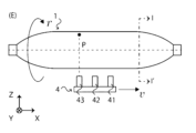
- FIG. 4A to 4F are schematic diagrams of the operation of the burner array in this embodiment.
- 4A, FIG. 4B, and FIG. 4E are side views of the optical fiber preform 1
- FIG. 4B, FIG. 4D, and FIG. 4F are the optical fiber preforms taken along the line II' in FIGS. 4A, FIG. 4C, and FIG. 4E, respectively.
- 1 is a sectional view of FIG.
- the optical fiber preform 1 rotates around the core axis of the core portion 11 at a rotational speed r [rpm].
- the number of burners N 3, and the burner array 4 includes three burners 41 to 43.
- the burner array 4 moves in the X direction at a moving speed v [mm/min] and deposits the porous glass portion 13 on the optical fiber preform 1 .
- L+x is the rotation speed of the optical fiber preform 1 and can be set by the operator.
- the rotation speed L is a natural number representing the integer part of the rotation speed of the optical fiber preform 1
- the rotation speed L controls the cycle of the flame trajectory of the burner 41 in the X direction. As the rotational speed L increases, the period of the trajectory of the flame of the burner 41 in the X direction becomes smaller, and the density of the glass particles deposited on the sides of the core part 11 by the burners 41 to 4N increases. As the rotational speed L decreases, the period of the trajectory of the flame of the burner 41 in the X direction increases, and the density of glass particles deposited on the sides of the core portion 11 by the burners 41 to 4N decreases.
- the rotation speed L may be determined according to the number N of burners and the distance d between the burners, or may be determined according to the deposition density of the porous glass portion 13 or the time required for the deposition process.
- the rotation speed L does not necessarily have to be constant and can be changed as appropriate. For example, it may be determined depending on the amount of accumulation, surface roughness, etc. of the porous glass portion 13. However, while the burner array 4 moves from one end of the optical fiber preform 1 to the other end and deposits glass particles, it is desirable that the rotation speed L is constant.
- the trajectory of the flame of the burner 41 overlaps with a point P on the side of the optical fiber preform 1. Since the burner 42 and the burner 43 are provided at a distance d and a distance 2d from the burner 41, respectively, the trajectory of the flame of the burner 42 and the trajectory of the flame of the burner 43 are a distance d and a distance 2d, respectively, from the point P in the X direction. It passes through a position 2d away.
- the offset x controls the distance of the flame trajectory of the burners 41-4N.
- the offset x is 0, the flame trajectories of the burners 41 to 4N overlap each other. If the trajectories of all the flames of the burners 41 to 4N overlap, the surface irregularities of the optical fiber preform 1 may become large. For this reason, consider the value of the offset x that will make the trajectories of the flames of the burners 41 to 4N evenly spaced and reduce the unevenness on the surface of the optical fiber preform 1.
- the distance in the X direction between point P and each flame trajectory is determined.
- the optical fiber base material 1 rotates once with reference to when the trajectory of the flame of the burner 41 overlaps with the point P
- the trajectory of the flame of the burner 41 is a distance from the point P in the X direction as shown by equation (1).
- Move d/(L+x) When the optical fiber preform 1 rotates L, the trajectory of the flame of the burner 42 and the point P are located on substantially the same straight line in the X direction. At this time, the distance in the X direction between the trajectory of the flame of the burner 42 and the point P is expressed by the following formula.
- the trajectory of the flame of the burner 4N and the point P are located on substantially the same straight line in the X direction.
- the distance in the X direction between the trajectory of the flame of the burner 4N and the point P is expressed by the following formula.
- equation (4) the ratio of the distance between the flame trajectory of burner 41 and the flame trajectory of burner 42 and the distance between the flame trajectory of burner 41 and the flame trajectory of burner 4N can be obtained. It will be done.
- the value of offset x is a value excluding 0, and is preferably set to a value greater than -1/(N-1) and smaller than +1/(N-1), and set to ⁇ 1/N. It is more preferable that
- equation (2) (distance between the trajectory of the flame of burner 41 and the trajectory of the flame of burner 42), equation (4) (distance between the trajectory of the flame of burner 41 and the flame trajectory of burner 44), (distance), and the value of equation (5).
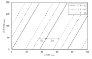
- 6A to 6D are developed views of the trajectories of the flames of the burners 41 to 44 formed on the sides of the optical fiber preform 1 in this embodiment.
- a developed view of the trajectory of the flames of the burners 41 to 44 is shown.
- the value of equation (2) and the value of equation (4) are both 7.89
- the value of equation (5) is 1.00. Therefore, the distance between the flame trajectory of burner 41 and the flame trajectory of burner 42 is equal to the distance between the flame trajectory of burner 41 and the flame trajectory of burner 44.
- the distance D2 between the flame locus of the burner 41 and the flame locus of the burner 42 is equal to the distance D4 between the flame locus of the adjacent burner 44 and the flame locus of the burner 41. All flame trajectories are equally spaced across the sides of 1.
- a developed view of the trajectory of the flames of the burners 41 to 44 is shown.
- the values of equation (2) and equation (4) are 8.56 and 6.03, respectively, and the value of equation (5) is 0.70. Therefore, the distance between the flame locus of the burner 41 and the flame locus of the burner 42 becomes large, and the distance between the flame locus of the burner 41 and the flame locus of the burner 44 becomes small.
- distance D4 is smaller than distance D2.
- a developed view of the trajectory of the flames of the burners 41 to 44 is shown.
- the values of equation (2) and equation (4) are 9.07 and 4.61, respectively, and the value of equation (5) is 0.51.
- the distance between the flame trajectory of the burner 41 and the flame trajectory of the burner 42 becomes further larger than in the case of condition (m) in FIG. 5, and the distance between the flame trajectory of the burner 41 and the flame trajectory of the burner 44 becomes smaller.
- the distance D4 is even smaller than the distance D2, and the surface irregularities of the optical fiber preform 1 may become large.
- a developed view of the trajectory of the flames of the burners 41 to 44 is shown.
- the values of equation (2) and equation (4) are 6.58 and 11.59, respectively, and the value of equation (5) is 1.76.
- the distance between the flame trajectory of burner 41 and the flame trajectory of burner 42 is small, and the distance between the flame trajectory of burner 41 and the flame trajectory of burner 44 is large.
- the distance D4 is larger than the distance D2, and the surface irregularities of the optical fiber preform 1 may become large.
- the value of formula (5) may be a value in the range of 3/4 to 4/3 (0.75 to 1.33), and may be in the range of 2/3 to 3/2 (0.67 to 1.50). Even if the value falls within this range, the unevenness on the surface of the optical fiber preform 1 may be within an acceptable range. Therefore, when equation (5) has a value in the range of 3/4 to 4/3 (0.75 to 1.33), is derived, and when equation (5) has a value in the range of 2/3 to 3/2 (0.67 to 1.50), is derived.
- Equation (2) (distance between the trajectory of the flame of burner 41 and the trajectory of the flame of burner 42), equation (4) (distance between the trajectory of the flame of burner 41 and the flame trajectory of burner 43), (distance), and the value of equation (5).
- 8A to 8D are developed views of the trajectories of the flames of the burners 41 to 43 formed on the sides of the optical fiber preform 1 in this embodiment.
- a developed view of the trajectory of flames Nos. 41 to 43 is shown.
- the values of equation (2) and equation (4) are 11.89 and 12.25, respectively, and the value of equation (5) is 1.03. Therefore, the distance between the flame trajectory of burner 41 and the flame trajectory of burner 42 is approximately equal to the distance between the flame trajectory of burner 41 and the flame trajectory of burner 43.
- the distance D2 between the flame locus of the burner 41 and the flame locus of the burner 42 is approximately equal to the distance D3 between the flame locus of the adjacent burner 43 and the flame locus of the burner 41. All flame trajectories are approximately equally spaced over the sides of the material 1.
- a developed view of the trajectory of flames Nos. 41 to 43 is shown.
- the values of equation (2) and equation (4) are 10.58 and 15.32, respectively, and the value of equation (5) is 1.45. Therefore, the distance between the flame trajectory of burner 41 and the flame trajectory of burner 42 becomes large, and the distance between the flame trajectory of burner 41 and the flame trajectory of burner 43 becomes small.
- distance D2 is slightly smaller than distance D3.
- a developed view of the trajectory of flames Nos. 41 to 43 is shown.
- the values of equation (2) and equation (4) are 13.81 and 7.79, respectively, and the value of equation (5) is 0.56.
- the distance between the flame trajectory of burner 41 and the flame trajectory of burner 42 is further increased than in the case of condition (f) in FIG. 7, and the distance between the flame trajectory of burner 41 and the flame trajectory of burner 43 is further decreased.
- the distance D3 is smaller than the distance D2, and the surface irregularities of the optical fiber preform 1 may become large.
- a developed view of the trajectory of flames Nos. 41 to 43 is shown.
- the values of equations (2) and (4) are 9.57 and 17.67, respectively, and the value of equation (5) is 1.85.
- the distance between the flame locus of burner 41 and the flame locus of burner 42 is small, and the distance between the flame locus of burner 41 and burner 43 is long.
- the distance D3 is larger than the distance D2, and the surface irregularities of the optical fiber preform 1 may become larger.
- the value of equation (5) is approximately 1.00.
- the value of equation (5) may be a value in the range of 3/4 to 4/3 (0.75 to 1.33), or 2/3 to 3/2 (0.67 to 1.50).
- equation (5) has a value in the range of 3/4 to 4/3 (0.75 to 1.33), is derived, and when equation (5) has a value in the range of 2/3 to 3/2 (0.67 to 1.50), is derived.
- the absolute value of the offset x becomes larger than ⁇ 1/N, the distance between the flame trajectory of burner 41 and the flame trajectory of burner 42 (distance D2 in FIGS. 6A to 6D and distance D2 in FIGS. 8A to 8D) increases. , the distance between the flame locus of burner 41 and the flame locus of burner 4N (distance D4 in FIGS. 6A to 6D and distance D3 in FIGS. 8A to 8D) becomes smaller.
- the absolute value of the offset is smaller than ⁇ 1/N, the distance between the flame trajectory of burner 41 and the flame trajectory of burner 42 (distance D2 in FIGS. 6A to 6D and distance D2 in FIGS. 8A to 8D) becomes small.
- the distance between the flame locus of burner 41 and the flame locus of burner 4N (distance D4 in FIGS. 6A to 6D and distance D3 in FIGS. 8A to 8D) increases. Therefore, by setting an appropriate value of the offset x according to the number N of burners, it is possible to manufacture an optical fiber preform with small surface irregularities.
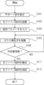
- FIG. 9 is a flowchart of a method for manufacturing an optical fiber preform and an optical fiber in the embodiment.
- the support parts 12A and 12B are joined to both ends of the core part 11 (step S101).
- the support parts 12A and 12B are melt-bonded to the core part 11 using an oxyhydrogen burner or the like so that the virtual support axes of the support parts 12A and 12B and the virtual core axis of the core part 11 are located on substantially the same line. .
- the core part 11 (optical fiber preform 1) to which the support parts 12A and 12B are joined is installed in the deposition apparatus 2 (step S103).
- the support parts 12A and 12B are each held by the grip part 23 of the deposition device 2.
- the offset x may be automatically set to an appropriate value according to the number N of burners.
- the rotation speed L may be automatically set to an appropriate value according to the number of burners N and the distance d between burners, or may be determined according to the deposition density of the porous glass portion 13 or the time required for the deposition process. You can.
- the operator sets the rotation speed r and the CPU 301 calculates the movement speed v in S105, the operator may set the movement speed v and the CPU 301 calculates the rotation speed r.
- the deposition device 2 rotates the optical fiber preform 1 at a rotational speed r, and the burner array 4 is supplied with frit, combustible gas, and auxiliary gas, Glass particles are deposited on the side of the core part 11 by the burner array 4 (step S107).
- the burner array 4 reciprocates in the X direction from the joint between the support section 12A and the core section 11 to the joint between the support section 12B and the core section 11 at a moving speed v.
- the burners 41 to 4N feed glass raw materials into the flame, and the generated glass particles are deposited on the side of the core portion 11 at intervals based on set parameters.
- the burner array 4 reciprocates in the X direction along the lower part of the core part 11 at a moving speed v until a predetermined amount of glass particles are deposited on the side of the core part 11 (NO in step S109). Deposits on the sides.
- a predetermined amount of glass particles are deposited on the side of the core part 11 (YES in step S109)
- the supply of glass raw material, combustible gas, and auxiliary gas to the burner array 4 is stopped, and the burner array 4 is extinguished.
- the deposition of a predetermined amount of glass particles may be determined, for example, by the thickness of the porous glass portion 13 in the Y direction or the Z direction, the difference in mass between the optical fiber preform 1 before and after deposition, and the like.
- the support parts 12A and 12B are removed from the grip part 23, and the optical fiber preform 1 is removed from the deposition apparatus 2 (step S111).
- the support part 12A is vertically supported at the upper part of the sintering apparatus, and the optical fiber preform 1 is installed in the sintering apparatus.
- the optical fiber preform 1 is heated and sintered by the sintering device (step S115). First, chlorine (Cl 2 ) or the like is introduced into the furnace tube of the sintering device from the gas introduction section. Next, the optical fiber preform 1 is heated by a heater while rotating in the furnace tube. As a result, impurities and the like contained in the optical fiber preform 1 are removed. Further, chlorine is discharged to the outside of the reactor core tube, and a mixed gas of chlorine and inert gas is introduced into the reactor core tube as an atmospheric gas.
- the optical fiber preform 1 is heated to a predetermined temperature by a heater while rotating in the furnace tube.
- the predetermined temperature may be, for example, 1500°C.
- helium is discharged to the outside of the furnace tube, and the transparent vitrified optical fiber preform 1 is taken out from the furnace tube.
- the transparent vitrified optical fiber preform 1 is heated and drawn.
- the optical fiber preform 1 is heated at a heating temperature of 2000 to 2300°C. In this way, an optical fiber is formed.
- the deposition of glass fine particles by a single burner is improved. It is efficient and makes it possible to reduce unevenness on the surface of the optical fiber preform.
- step S107 of FIG. 9 the burner array 4 deposits glass particles on the side of the core part 11 while moving from one end of the optical fiber preform 1 to the other end in the X direction.
- the control device 3 stores the initial phase ⁇ 1 of the rotation angle of the optical fiber preform 1 when the burner array 4 starts moving from one end. This series of steps is called the first outward deposition step.
- the control device 3 stores the initial phase ⁇ 2 of the rotation angle of the optical fiber preform 1 when the burner array 4 starts moving from the other end. Such a series of steps is called the first return pass deposition step.
- the burner array 4 moves to one end of the optical fiber preform 1, the burner array 4 starts moving from the one end of the optical fiber preform 1.
- the control device 3 controls the initial phase ⁇ 3 of the rotation angle of the optical fiber preform 1 to a value different from the initial phase ⁇ 1.
- the difference between the initial phases ⁇ 1, ⁇ 3 may be less than the absolute value of the offset x, which is greater than zero. That is, there is a difference between the trajectory of the flame of the burner 41 formed in the first outgoing deposition process and the flame trajectory of the burner 42 formed in the first outgoing deposition process.
- the initial phase ⁇ 3 may be set such that a flame trajectory is formed.
- the control device 3 controls the initial phase ⁇ 4 of the rotation angle of the optical fiber preform 1 to a value different from the initial phase ⁇ 2.
- the difference between the initial phases ⁇ 2, ⁇ 4 may be less than the absolute value of the offset x, which is greater than zero.
- the initial phase ⁇ 4 may be set so that the trajectory of the flame of the burner 4N in the process is formed.
- the control device 3 controls the initial phase ⁇ 5 of the rotation angle of the optical fiber preform 1 to a value different from the initial phase ⁇ 3.
- the difference between the initial phases ⁇ 3, ⁇ 5 may be greater than 0 and less than the absolute value of the offset x. That is, there is a difference between the trajectory of the flame of the burner 41 formed in the second outgoing deposition process and the flame trajectory of the burner 42 formed in the first outgoing deposition process.
- the initial phase ⁇ 5 may be set such that a flame trajectory is formed.
- the initial phase of the burner array 4 is set for each deposition process, and the burner array 4 deposits glass particles on the side of the core part 11.
- the predetermined angle may be calculated based on the number of times the deposition process is performed to obtain a predetermined amount of deposited in S109, or may be determined based on the distribution of the amount of deposited glass particles of the burners 41 to 4N.
- the predetermined angle added to the initial phase at one end of the optical fiber preform 1 may be the same as the predetermined angle added to the initial phase at the other end, or different predetermined angles may be added to the initial phase at the other end. It may be added to the initial phase.
- burners 41 to 4N are used for the first outbound pass, the second outbound pass, the third outbound pass, and so on.
- the initial phase is set so that the flame trajectories of the two do not overlap each other.
- burners 41 to 4N are used for the first return trip, the second return trip, the third return trip, etc.
- the initial phase is set so that the flame trajectories of the two do not overlap each other.
- the relationship between the moving speed of a burner array including a plurality of burners and the rotational speed of the core rod is defined, and the initial phase of the flame trajectory of the burner array is determined for each deposition process.
- the deposition efficiency is better than the deposition of glass particles using a single burner, and it is possible to reduce the unevenness on the surface of the optical fiber preform.
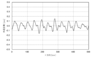
- FIG. 10A is a diagram showing variations in the outer diameter of the optical fiber preform 1 in this example.
- the average thickness of the deposited porous glass portion 13 was about 200 mm.
- the outer diameter variation was -0.04 to 0.04 mm or less, and an optical fiber preform 1 with small surface irregularities could be manufactured. Note that the standard deviation of the outer diameter variation in FIG. 10A was 1.26 ⁇ 10 ⁇ 2 [mm].
- FIG. 10B is a diagram showing variations in the outer diameter of the optical fiber preform 1 in this example.
- the average thickness of the deposited porous glass portion 13 was about 200 mm.
- the outer diameter variation was ⁇ 0.07 to 0.07 mm or less, and an optical fiber preform 1 with small surface irregularities could be manufactured.
- the value of equation (5) is 0.70, and if the value of equation (5) is within the range of 2/3 to 3/2 (0.67 to 1.50), the light The surface unevenness of the fiber base material 1 was within an acceptable range.
- the standard deviation of the outer diameter variation in FIG. 10B was 2.53 ⁇ 10 ⁇ 2 [mm].
- the optical fiber preform 1 is manufactured by the manufacturing method of the first embodiment, and a part of the side part of the optical fiber preform 1 has a substantially cylindrical shape.
- the variation in outer diameter was investigated.
- FIG. 10C is a diagram showing variations in the outer diameter of the optical fiber preform 1 in this example.
- the average thickness of the deposited porous glass portion 13 was about 200 mm.
- the outer diameter variation was -0.17 to 0.17 mm or less, with some variations exceeding 0.1 mm.
- the value of equation (5) is 0.51, and if the value of equation (5) is outside the range of 2/3 to 3/2 (0.67 to 1.50), the optical fiber The surface irregularities of Material 1 became large. Note that the standard deviation of the outer diameter variation in FIG. 10C was 6.22 ⁇ 10 ⁇ 2 [mm].
- Optical fiber base material 2 Deposition device 3: Control device 4: Burner array
Landscapes
- Chemical & Material Sciences (AREA)
- Engineering & Computer Science (AREA)
- Organic Chemistry (AREA)
- Materials Engineering (AREA)
- Manufacturing & Machinery (AREA)
- Geochemistry & Mineralogy (AREA)
- Life Sciences & Earth Sciences (AREA)
- General Life Sciences & Earth Sciences (AREA)
- Chemical Kinetics & Catalysis (AREA)
- Physics & Mathematics (AREA)
- Crystallography & Structural Chemistry (AREA)
- Optics & Photonics (AREA)
- General Chemical & Material Sciences (AREA)
- Manufacture, Treatment Of Glass Fibers (AREA)
- Glass Melting And Manufacturing (AREA)
Abstract
Description












本実施形態では、バーナーアレイが往復移動を繰り返す際に、コアロッドの回転角度の初期位相が制御される。以下、本実施形態について、第1実施形態と異なる構成を中心に説明する。第1実施形態と同様の構成要素には同一の符号を付し、説明を省略し、または簡潔にする。
回転数L=5、バーナー数N=4、バーナー間の距離d=150[mm]、光ファイバ母材1の回転速度r=30[rpm]、オフセットx=-0.25として(図5の条件(k)の場合)、第1実施形態の製造方法により光ファイバ母材1を製造し、光ファイバ母材1の側部が略円柱形をなす部位(テーパー部14A、14Bを除く部位)における一部の外径変動を調べた。図10Aは、本実施例における光ファイバ母材1の外径変動を示す図である。堆積した多孔質ガラス部13の厚さの平均は、約200mmであった。図10Aに示すように、外径変動は-0.04~0.04mm以下であり、表面の凹凸が小さい光ファイバ母材1を製造することができた。なお、図10Aにおける外径変動の標準偏差は1.26×10⁻²[mm]であった。
回転数L=5、バーナー数N=4、バーナー間の距離d=150[mm]、光ファイバ母材1の回転速度r=30[rpm]、オフセットx=-0.27として(図5の条件(m)の場合)、第1実施形態の製造方法により光ファイバ母材1を製造し、光ファイバ母材1の側部が略円柱形をなす部位における一部の外径変動を調べた。図10Bは、本実施例における光ファイバ母材1の外径変動を示す図である。堆積した多孔質ガラス部13の厚さの平均は、約200mmであった。図10Bに示すように、外径変動は-0.07~0.07mm以下であり、表面の凹凸が小さい光ファイバ母材1を製造することができた。本実施例において、(5)式の値は0.70であり、(5)式の値が2/3~3/2(0.67~1.50)の範囲内の値であれば光ファイバ母材1の表面の凹凸は許容範囲であった。なお、図10Bにおける外径変動の標準偏差は2.53×10-2[mm]であった。
一方、比較例として、回転数L=5、バーナー数N=4、バーナー間の距離d=150[mm]、光ファイバ母材1の回転速度r=30[rpm]、オフセットx=-0.29として(図5の条件(n)の場合)、第1実施形態の製造方法により光ファイバ母材1を製造し、光ファイバ母材1の側部が略円柱形をなす部位における一部の外径変動を調べた。図10Cは、本実施例における光ファイバ母材1の外径変動を示す図である。堆積した多孔質ガラス部13の厚さの平均は、約200mmであった。図10Cに示すように、外径変動は-0.17~0.17mm以下であり、一部に0.1mmを超える変動を生じた。本比較例において、(5)式の値は0.51であり、(5)式の値が2/3~3/2(0.67~1.50)の範囲外の値では光ファイバ母材1の表面の凹凸が大きくなった。なお、図10Cにおける外径変動の標準偏差は6.22×10-2[mm]であった。
2 :堆積装置
3 :制御装置
4 :バーナーアレイ
Claims (9)
- コアロッドの長手方向に延在する前記コアロッドの回転軸を中心に回転速度rで前記コアロッドを回転する支持部と、
距離dの間隔で設けられるN組(Nは2以上の整数)のバーナーおよび原料噴出口を備え、前記コアロッドの周囲を前記長手方向に速度vで移動し、前記コアロッドの外周に多孔質ガラス部を形成する少なくとも1つのバーナーアレイと、を備え、
前記バーナーアレイが前記長手方向に前記距離dだけ移動するときの前記コアロッドの回転数(L+x)が、


- さらに前記オフセットxの絶対値が、

- さらに前記オフセットxが、

- 前記速度vまたは前記回転速度rのいずれか一方を決定すると、他方が決定されることを特徴とする請求項1に記載の光ファイバ母材の製造装置。
- 前記バーナーアレイは、前記コアロッドの一方の端部から他方の端部までの移動を繰り返し実行可能であって、
第1の移動を開始する際における前記コアロッドの回転角の第1の初期位相と、前記第1の移動に続く第2の移動を開始する際における前記コアロッドの回転角の第2の初期位相とは互いに異なることを特徴とする請求項1に記載の光ファイバ母材の製造装置。 - 前記第1の初期位相と前記第2の初期位相との差は、0より大きく前記オフセットxの絶対値未満であることを特徴とする請求項5に記載の光ファイバ母材の製造装置。
- 少なくとも1つのバーナーアレイがコアロッドの外周に多孔質ガラス部を形成する工程を備え、
前記コアロッドは、前記コアロッドの長手方向に延在する前記コアロッドの回転軸を中心に回転速度rで回転し、
前記バーナーアレイは、距離dの間隔で設けられるN組(Nは2以上の整数)のバーナーおよび原料噴出口を備え、前記コアロッドの周囲を前記長手方向に速度vで移動し、
前記バーナーアレイが前記長手方向に前記距離dだけ移動するときの前記コアロッドの回転数(L+x)が、


- 請求項1に記載の光ファイバ母材の製造装置によって製造した光ファイバ母材。
- 請求項8に記載の光ファイバ母材を高温で線引きし、製造した光ファイバ。
Priority Applications (1)
| Application Number | Priority Date | Filing Date | Title |
|---|---|---|---|
| US18/965,014 US20250171346A1 (en) | 2022-07-21 | 2024-12-02 | Apparatus for manufacturing optical fiber preform, method for manufacturing optical fiber preform, optical fiber preform and optical fiber |
Applications Claiming Priority (2)
| Application Number | Priority Date | Filing Date | Title |
|---|---|---|---|
| JP2022-116690 | 2022-07-21 | ||
| JP2022116690A JP7869064B2 (ja) | 2022-07-21 | 2022-07-21 | 光ファイバ母材の製造装置、製造方法、光ファイバ母材および光ファイバ |
Related Child Applications (1)
| Application Number | Title | Priority Date | Filing Date |
|---|---|---|---|
| US18/965,014 Continuation US20250171346A1 (en) | 2022-07-21 | 2024-12-02 | Apparatus for manufacturing optical fiber preform, method for manufacturing optical fiber preform, optical fiber preform and optical fiber |
Publications (1)
| Publication Number | Publication Date |
|---|---|
| WO2024018917A1 true WO2024018917A1 (ja) | 2024-01-25 |
Family
ID=89617816
Family Applications (1)
| Application Number | Title | Priority Date | Filing Date |
|---|---|---|---|
| PCT/JP2023/025183 Ceased WO2024018917A1 (ja) | 2022-07-21 | 2023-07-06 | 光ファイバ母材の製造装置、製造方法、光ファイバ母材および光ファイバ |
Country Status (3)
| Country | Link |
|---|---|
| US (1) | US20250171346A1 (ja) |
| JP (1) | JP7869064B2 (ja) |
| WO (1) | WO2024018917A1 (ja) |
Citations (3)
| Publication number | Priority date | Publication date | Assignee | Title |
|---|---|---|---|---|
| JP2003081645A (ja) * | 2001-07-02 | 2003-03-19 | Sumitomo Electric Ind Ltd | ガラス微粒子堆積体の製造方法及びその製造方法で得られたガラス微粒子堆積体 |
| JP2013043810A (ja) * | 2011-08-25 | 2013-03-04 | Sumitomo Electric Ind Ltd | ガラス微粒子堆積体の製造方法 |
| JP2022018230A (ja) * | 2020-07-15 | 2022-01-27 | 信越石英株式会社 | 大型中空状多孔質石英ガラス母材及びその製造方法 |
Family Cites Families (12)
| Publication number | Priority date | Publication date | Assignee | Title |
|---|---|---|---|---|
| JPH0692670A (ja) * | 1992-09-11 | 1994-04-05 | Fujikura Ltd | ガラス母材の製造装置 |
| JPH11116263A (ja) * | 1997-10-15 | 1999-04-27 | Hitachi Cable Ltd | 光ファイバ母材の製造方法 |
| CN101549950B (zh) * | 2000-07-31 | 2011-03-09 | 信越化学工业株式会社 | 玻璃母材制造装置及玻璃母材制造方法 |
| JP3521865B2 (ja) * | 2000-10-27 | 2004-04-26 | 住友電気工業株式会社 | ガラス微粒子堆積体の製造方法 |
| JP4467197B2 (ja) * | 2001-02-26 | 2010-05-26 | 信越化学工業株式会社 | 多孔質ガラス母材の製造装置および製造方法 |
| US8516855B2 (en) * | 2001-04-27 | 2013-08-27 | Prysmian Cavi E Sistemi Energia S.R.L. | Method for producing an optical fiber preform |
| JP4169260B2 (ja) * | 2003-02-04 | 2008-10-22 | 信越石英株式会社 | 外径変動が小さく、両端の不良部の少ないスート法による光ファイバ用ガラス母材の製造方法 |
| JP2005225702A (ja) * | 2004-02-12 | 2005-08-25 | Sumitomo Electric Ind Ltd | ガラス微粒子堆積体の製造方法 |
| JP4558547B2 (ja) * | 2005-03-14 | 2010-10-06 | 古河電気工業株式会社 | 光ファイバ母材の製造方法 |
| JP6245648B2 (ja) * | 2014-06-16 | 2017-12-13 | 信越化学工業株式会社 | 光ファイバ母材の製造方法 |
| KR101655271B1 (ko) * | 2016-04-27 | 2016-09-07 | 주식회사 에스티아이 | 생산 효율이 향상된 광섬유 모재의 제조방법 |
| JP6570489B2 (ja) * | 2016-08-16 | 2019-09-04 | 信越化学工業株式会社 | ガラス微粒子堆積体の製造装置 |
-
2022
- 2022-07-21 JP JP2022116690A patent/JP7869064B2/ja active Active
-
2023
- 2023-07-06 WO PCT/JP2023/025183 patent/WO2024018917A1/ja not_active Ceased
-
2024
- 2024-12-02 US US18/965,014 patent/US20250171346A1/en active Pending
Patent Citations (3)
| Publication number | Priority date | Publication date | Assignee | Title |
|---|---|---|---|---|
| JP2003081645A (ja) * | 2001-07-02 | 2003-03-19 | Sumitomo Electric Ind Ltd | ガラス微粒子堆積体の製造方法及びその製造方法で得られたガラス微粒子堆積体 |
| JP2013043810A (ja) * | 2011-08-25 | 2013-03-04 | Sumitomo Electric Ind Ltd | ガラス微粒子堆積体の製造方法 |
| JP2022018230A (ja) * | 2020-07-15 | 2022-01-27 | 信越石英株式会社 | 大型中空状多孔質石英ガラス母材及びその製造方法 |
Also Published As
| Publication number | Publication date |
|---|---|
| JP7869064B2 (ja) | 2026-06-02 |
| US20250171346A1 (en) | 2025-05-29 |
| JP2024014098A (ja) | 2024-02-01 |
Similar Documents
| Publication | Publication Date | Title |
|---|---|---|
| US10399888B2 (en) | Method for producing glass particulate deposit and method for producing glass preform | |
| JPH039047B2 (ja) | ||
| US11993532B2 (en) | Enhanced particle deposition system and method | |
| CN108349780B (zh) | 光纤用玻璃母材的制造方法 | |
| US9676657B2 (en) | Method for producing glass particulate deposit and method for producing glass preform | |
| RU2284968C2 (ru) | Способ изготовления оптического стекла | |
| JP2024014098A (ja) | 光ファイバ母材の製造装置、製造方法、光ファイバ母材および光ファイバ | |
| KR100496449B1 (ko) | 광섬유모재 제조를 위한 외부기상 증착장치 및 이를 이용한 광섬유모재 제조방법 | |
| US20050076680A1 (en) | Method and apparatus for manufacturing optical fiber preforms using the outside vapor deposition process | |
| JP7393985B2 (ja) | 光ファイバ母材の製造装置及び光ファイバ母材の製造方法 | |
| CN111032587B (zh) | 玻璃微粒沉积体的制造方法、玻璃母材的制造方法以及玻璃微粒沉积体 | |
| EP3608296B1 (en) | Manufacturing device and manufacturing method for optical fiber porous preform | |
| KR100630117B1 (ko) | 기상 외부 증착 방법에 의한 광섬유 모재 제작 장치 | |
| US20230331618A1 (en) | Method and facility for producing optical fiber base material | |
| JP2004269285A (ja) | ガラス微粒子堆積体の製造法 | |
| JP4420082B2 (ja) | ガラス母材の製造方法 | |
| JP4483434B2 (ja) | ガラス母材の製造方法 | |
| JP2002338257A (ja) | ガラス微粒子堆積体製造装置及び製造方法 | |
| HK40057103A (en) | Enhanced particle deposition system and method | |
| JP3953855B2 (ja) | 多孔質母材の製造方法 | |
| JP2003212551A (ja) | ガラス母材の製造方法および製造装置 | |
| JP2024030361A (ja) | ガラス母材の製造方法 | |
| US20020073743A1 (en) | Method and apparatus for making optical fiber preform | |
| KR20020008433A (ko) | 광섬유 프리폼 제조장치 및 제조방법 | |
| HK1245187B (en) | System and method for depositing silica particles |
Legal Events
| Date | Code | Title | Description |
|---|---|---|---|
| 121 | Ep: the epo has been informed by wipo that ep was designated in this application |
Ref document number: 23842842 Country of ref document: EP Kind code of ref document: A1 |
|
| WWE | Wipo information: entry into national phase |
Ref document number: 202547012841 Country of ref document: IN |
|
| WWP | Wipo information: published in national office |
Ref document number: 202547012841 Country of ref document: IN |
|
| NENP | Non-entry into the national phase |
Ref country code: DE |
|
| 122 | Ep: pct application non-entry in european phase |
Ref document number: 23842842 Country of ref document: EP Kind code of ref document: A1 |