WO2024018801A1 - インクジェットヘッド - Google Patents
インクジェットヘッド Download PDFInfo
- Publication number
- WO2024018801A1 WO2024018801A1 PCT/JP2023/022807 JP2023022807W WO2024018801A1 WO 2024018801 A1 WO2024018801 A1 WO 2024018801A1 JP 2023022807 W JP2023022807 W JP 2023022807W WO 2024018801 A1 WO2024018801 A1 WO 2024018801A1
- Authority
- WO
- WIPO (PCT)
- Prior art keywords
- ink
- pressure
- temperature difference
- chamber
- pressure chambers
- Prior art date
- Legal status (The legal status is an assumption and is not a legal conclusion. Google has not performed a legal analysis and makes no representation as to the accuracy of the status listed.)
- Ceased
Links
Images






Classifications
-
- B—PERFORMING OPERATIONS; TRANSPORTING
- B41—PRINTING; LINING MACHINES; TYPEWRITERS; STAMPS
- B41J—TYPEWRITERS; SELECTIVE PRINTING MECHANISMS, i.e. MECHANISMS PRINTING OTHERWISE THAN FROM A FORME; CORRECTION OF TYPOGRAPHICAL ERRORS
- B41J2/00—Typewriters or selective printing mechanisms characterised by the printing or marking process for which they are designed
- B41J2/005—Typewriters or selective printing mechanisms characterised by the printing or marking process for which they are designed characterised by bringing liquid or particles selectively into contact with a printing material
- B41J2/01—Ink jet
- B41J2/135—Nozzles
- B41J2/14—Structure thereof only for on-demand ink jet heads
- B41J2/14016—Structure of bubble jet print heads
- B41J2/14032—Structure of the pressure chamber
- B41J2/14056—Plural heating elements per ink chamber
-
- B—PERFORMING OPERATIONS; TRANSPORTING
- B41—PRINTING; LINING MACHINES; TYPEWRITERS; STAMPS
- B41J—TYPEWRITERS; SELECTIVE PRINTING MECHANISMS, i.e. MECHANISMS PRINTING OTHERWISE THAN FROM A FORME; CORRECTION OF TYPOGRAPHICAL ERRORS
- B41J2/00—Typewriters or selective printing mechanisms characterised by the printing or marking process for which they are designed
- B41J2/005—Typewriters or selective printing mechanisms characterised by the printing or marking process for which they are designed characterised by bringing liquid or particles selectively into contact with a printing material
- B41J2/01—Ink jet
- B41J2/015—Ink jet characterised by the jet generation process
- B41J2/04—Ink jet characterised by the jet generation process generating single droplets or particles on demand
- B41J2/045—Ink jet characterised by the jet generation process generating single droplets or particles on demand by pressure, e.g. electromechanical transducers
- B41J2/04501—Control methods or devices therefor, e.g. driver circuits, control circuits
- B41J2/04563—Control methods or devices therefor, e.g. driver circuits, control circuits detecting head temperature; Ink temperature
-
- B—PERFORMING OPERATIONS; TRANSPORTING
- B41—PRINTING; LINING MACHINES; TYPEWRITERS; STAMPS
- B41J—TYPEWRITERS; SELECTIVE PRINTING MECHANISMS, i.e. MECHANISMS PRINTING OTHERWISE THAN FROM A FORME; CORRECTION OF TYPOGRAPHICAL ERRORS
- B41J2/00—Typewriters or selective printing mechanisms characterised by the printing or marking process for which they are designed
- B41J2/005—Typewriters or selective printing mechanisms characterised by the printing or marking process for which they are designed characterised by bringing liquid or particles selectively into contact with a printing material
- B41J2/01—Ink jet
- B41J2/135—Nozzles
- B41J2/14—Structure thereof only for on-demand ink jet heads
-
- B—PERFORMING OPERATIONS; TRANSPORTING
- B41—PRINTING; LINING MACHINES; TYPEWRITERS; STAMPS
- B41J—TYPEWRITERS; SELECTIVE PRINTING MECHANISMS, i.e. MECHANISMS PRINTING OTHERWISE THAN FROM A FORME; CORRECTION OF TYPOGRAPHICAL ERRORS
- B41J2/00—Typewriters or selective printing mechanisms characterised by the printing or marking process for which they are designed
- B41J2/005—Typewriters or selective printing mechanisms characterised by the printing or marking process for which they are designed characterised by bringing liquid or particles selectively into contact with a printing material
- B41J2/01—Ink jet
- B41J2/17—Ink jet characterised by ink handling
-
- B—PERFORMING OPERATIONS; TRANSPORTING
- B41—PRINTING; LINING MACHINES; TYPEWRITERS; STAMPS
- B41J—TYPEWRITERS; SELECTIVE PRINTING MECHANISMS, i.e. MECHANISMS PRINTING OTHERWISE THAN FROM A FORME; CORRECTION OF TYPOGRAPHICAL ERRORS
- B41J2/00—Typewriters or selective printing mechanisms characterised by the printing or marking process for which they are designed
- B41J2/005—Typewriters or selective printing mechanisms characterised by the printing or marking process for which they are designed characterised by bringing liquid or particles selectively into contact with a printing material
- B41J2/01—Ink jet
- B41J2/17—Ink jet characterised by ink handling
- B41J2/175—Ink supply systems ; Circuit parts therefor
Definitions
- the present disclosure relates to an inkjet head.
- Patent Document 1 discloses an inkjet head that includes a plurality of nozzles and a plurality of pressure chambers provided corresponding to each of the plurality of nozzles.
- the plurality of pressure chambers communicate with each other via a common ink chamber, and ink is supplied to each pressure chamber via the common ink chamber. Then, by applying pressure to the ink in each pressure chamber, the ink is ejected through the nozzle.
- An inkjet head includes: a first nozzle and a second nozzle that eject ink; a first pressure chamber connected to the first nozzle; a second pressure chamber connected to the second nozzle; a first pressure variation unit that varies the pressure of the ink in the first pressure chamber and discharges the ink through the first nozzle; a second pressure variation unit that varies the pressure of the ink in the second pressure chamber and discharges the ink through the second nozzle;
- the apparatus further includes a temperature difference generating section that generates a temperature difference between the ink supplied to the first pressure chamber and the ink supplied to the second pressure chamber.
- FIG. 1 is a perspective view illustrating an inkjet head according to a first embodiment.
- FIG. 2 is a bottom view illustrating the inkjet head according to the first embodiment.
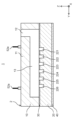
- FIG. 3 is a cross-sectional view taken along line II in FIG. 2, and is a vertical cross-sectional view showing an ink flow path from a common ink chamber to a nozzle.
- FIG. 4 is a cross-sectional view taken along line II-II in FIG. 3, and is a vertical cross-sectional view showing the relationship between the ink supply path and the common ink chamber.
- FIG. 4 is a cross-sectional view taken along line III-III in FIG.
- FIG. 3 is a cross-sectional view showing the relationship among a common ink chamber, a plurality of branch channels, and a plurality of pressure chambers.
- FIG. 4 is a cross-sectional view taken along line IV-IV in FIG. 3, and is a vertical cross-sectional view showing the positional relationship between a plurality of pressure fluctuation parts and a plurality of pressure chambers.
- FIG. 4 is a cross-sectional view taken along the line VV in FIG. 3, and is a vertical cross-sectional view showing the positional relationship between a plurality of pressure fluctuation parts and a plurality of pressure chambers. 4 is a sectional view taken along line VI-VI in FIG. 3, showing the configuration of a temperature difference generating section.
- FIG. 4 is a cross-sectional view taken along line VI-VI in FIG. 3, showing the configuration of a temperature difference generating section.
- FIG. 4 is a cross-sectional view taken along line VII-VII in FIG. 3, and is a diagram showing the configuration of a temperature difference generating section.
- FIG. 7 is a vertical cross-sectional view illustrating an inkjet head according to Modification Example 1, and is a vertical cross-sectional view showing an ink flow path from a common ink chamber to a nozzle.
- FIG. 7 is a diagram illustrating a temperature difference generation unit according to Modification 1.
- FIG. 7 is a vertical cross-sectional view illustrating an inkjet head according to Modification Example 2, and is a vertical cross-sectional view showing an ink flow path from a common ink chamber to a nozzle.
- FIG. 7 is a vertical cross-sectional view illustrating an inkjet head according to Modification 3, and is a vertical cross-sectional view showing an ink flow path from a common ink chamber to a nozzle.
- FIG. 7 is a vertical cross-sectional view illustrating an inkjet head according to a second embodiment, and is a vertical cross-sectional view showing an ink flow path from a common ink chamber to a nozzle.
- FIG. 15 is a cross-sectional view taken along line VIII-VIII in FIG. 14, and is a diagram showing the configuration of a temperature difference generating section.
- 7 is a longitudinal cross-sectional view illustrating an inkjet head according to modification 5, and is a diagram illustrating the configuration of a temperature difference generation section.
- FIG. FIG. 7 is a vertical cross-sectional view illustrating an inkjet head according to modification 5, and is a vertical cross-sectional view showing the relationship between an ink supply path and a common ink chamber.
- pressure waves When pressure is applied to the ink within the pressure chamber, pressure waves are generated within the pressure chamber. Pressure waves generated within each pressure chamber may propagate to the common ink chamber and resonate. In this case, the vibrations resonated in the common ink chamber return to each pressure chamber, making it impossible to normally eject ink from each nozzle.
- An object of the present disclosure is to provide an inkjet head that suppresses the mutual influence of ink ejection through one nozzle and ink ejection through another nozzle.
- the Z-axis direction is the height direction of the inkjet head 1
- the Y-axis direction is the longitudinal direction of the inkjet head 1
- the X-axis direction is the width direction of the inkjet head 1.
- FIG. 1 is a perspective view illustrating an inkjet head 1 according to the first embodiment.
- FIG. 2 is a bottom view illustrating the inkjet head 1.
- FIG. 3 is a cross-sectional view taken along the line II in FIG. 2, and is a vertical cross-sectional view showing the ink flow path from the common ink chamber 13 to the nozzles 411 and 421.
- the inkjet head 1 ejects ink through a plurality of nozzles 411 to 416 and 421 to 426 formed on the bottom surface thereof.
- the inkjet head 1 includes a main body section 2, pressure variation elements 3 and 4, and temperature difference generation sections 5A and 5B.
- the main body portion 2 is formed, for example, in the shape of a rectangular parallelepiped.
- the main body 2 includes a first main body 10 , a second main body 20 , a diaphragm 30 , and a nozzle plate 40 .
- the main body 2 is formed by overlapping the nozzle plate 40, the second main body 20, the diaphragm 30, and the first main body 10 in this order.
- the first main body portion 10 is, for example, formed in the shape of a rectangular parallelepiped. It constitutes the upper part of the main body part 2.
- the first main body portion 10 is formed, for example, by cutting alloy steel such as stainless steel.
- the second main body part 20 is formed, for example, in the shape of a rectangular parallelepiped, and constitutes the lower part of the main body part 2.
- the second main body portion 20 is formed, for example, by laminating stainless steel plates molded by etching or press working by adhesion, diffusion bonding, or the like.
- the diaphragm 30 is arranged between the first main body part 10 and the second main body part 20 so that its plate surface is perpendicular to the Z-axis direction.
- the diaphragm 30 is a thin plate-like elastic body.
- the diaphragm 30 is formed of, for example, a stainless steel plate or a nickel electroformed plate.
- the diaphragm 30 has a plurality of protrusions 30a that protrude in the positive direction of the Z-axis, and the plurality of protrusions 30a are arranged in the Y-axis direction (see FIG. 6).
- the nozzle plate 40 is arranged on the bottom surface of the second main body part 20 so that its plate surface is perpendicular to the Z-axis direction, and forms the bottom part of the main body part 2.
- the nozzle plate 40 is formed by, for example, molding a stainless steel plate by etching, pressing, laser processing, or the like.
- FIG. 4 is a cross-sectional view taken along line II-II in FIG. 3, and is a vertical cross-sectional view showing the relationship between the ink supply path 12 and the common ink chamber 13.
- the first main body section 10 includes a housing section 11 that is arranged at the center in the X-axis direction and extends in the Y-axis direction. As shown in FIG. 4, the housing 11 has an ink supply path 12 and a common ink chamber 13 formed therein.
- the ink supply path 12 is provided, for example, at one end of the housing section 11 in the X-axis direction, and extends along the Z-axis direction. Further, the ink supply path 12 is connected to a common ink chamber 13. Ink stored in an ink tank (not shown) is supplied to a common ink chamber 13 via an ink supply path 12.
- the common ink chamber 13 is formed, for example, in the shape of a rectangular parallelepiped with long sides along the Y-axis direction.
- the common ink chamber 13 stores ink supplied from the ink supply path 12.
- FIG. 5 is a cross-sectional view taken along line III-III in FIG.
- FIG. 6 is a cross-sectional view taken along line IV-IV in FIG. 3, and is a vertical cross-sectional view showing the positional relationship between the plurality of pressure fluctuation parts 31 to 36 and the plurality of pressure chambers 241 to 246.
- FIG. 7 is a cross-sectional view taken along the line VV in FIG. 3, and is a vertical cross-sectional view showing the positional relationship between the plurality of pressure fluctuation parts 41 to 46 and the plurality of pressure chambers 251 to 256.
- the second main body 20 includes a plurality of branch channels 221 to 226, 231 to 236, a plurality of pressure chambers 241 to 246, 251 to 256, and a plurality of pressure chambers 241 to 246, 251 to 256. Silo portions 261 to 266 and 271 to 276 are formed.
- the set of branch flow path, pressure chamber, and silo part corresponds to the nozzle on a one-to-one basis. That is, the number of sets of branch channels, pressure chambers, and silo parts is the same as the number of nozzles.
- branch channels 221 to 226 will be referred to as “left branch channels 221 to 226", and the branch channels 231 to 236 will be referred to as “right branch channels 231 to 236".
- the pressure chambers 241 to 246 are referred to as “left pressure chambers 241 to 246”
- the pressure chambers 251 to 256 are referred to as “right pressure chambers 251 to 256”.
- the silo parts 261 to 266 are referred to as “left silo parts 261 to 266”
- the silo parts 271 to 276 are referred to as "right silo parts 271 to 276”.
- the nozzles 411 to 416 are referred to as “left nozzles 411 to 416”
- the nozzles 421 to 426 are referred to as "right nozzles 421 to 426.”
- the left branch flow paths 221 to 226 are branched from the common ink chamber 13 in the negative direction of the X axis, for example, and are connected to the left pressure chambers 241 to 246.
- the right branch channels 231 to 236 are branched from the common ink chamber 13 in the positive direction of the X-axis, and are connected to the right pressure chambers 251 to 256, for example.
- the ink in the common ink chamber 13 is supplied to the left pressure chambers 241 to 246 via the left branch channels 221 to 226, and is also supplied to the right pressure chambers 251 to 256 via the right branch channels 231 to 236. Supplied.
- the left pressure chambers 241 to 246 are arranged in the Y-axis direction, and the right pressure chambers 251 to 256 are arranged in the Y-axis direction as a separate column from the left pressure chambers 241 to 246.
- the left pressure chambers 241 to 246 and the right pressure chambers 251 to 256 are formed, for example, in the shape of a rectangular parallelepiped with long sides along the X-axis direction. As shown in FIGS. 6 and 7, the upper walls of the left pressure chambers 241 to 246 and the right pressure chambers 251 to 256 are formed by a diaphragm 30. Note that the above-mentioned convex portions 30a are arranged on the upper wall portions of the left pressure chambers 241 to 246 and the right pressure chambers 251 to 256 in the diaphragm 30.
- the left silo parts 261 to 266 are connected to the left pressure chambers 241 to 246 and the left nozzles 411 to 416, respectively.
- the right silo parts 271 to 276 are connected to the right pressure chambers 251 to 256 and the right nozzles 421 to 426, respectively.
- the left silo parts 261 to 266 and the right silo parts 271 to 276 are formed, for example, in a cylindrical shape with a central axis along the Z-axis direction. Ink is stored in the left silo parts 261 to 266 and the right silo parts 271 to 276.
- the ink in the left pressure chambers 241 to 246 is supplied to the left nozzles 411 to 416 via the left silo parts 261 to 266.
- the ink in the right pressure chambers 251 to 256 is supplied to the right nozzles 421 to 426 via the right silo parts 271 to 276.
- main body portion 2 may be formed with a recovery channel for recovering ink from the left pressure chambers 241 to 246 and a recovery channel to recover ink from the right pressure chambers 251 to 256. .
- the nozzle plate 40 will be explained using FIG. 2 and FIGS. 6 to 7.
- the nozzle plate 40 is formed with left nozzles 411 to 416 and right nozzles 421 to 426. As shown in FIGS. 6 and 7, the left nozzles 411 to 416 and the right nozzles 421 to 426 pass through the nozzle plate 40. As shown in FIG. 2, the left nozzles 411 to 416 are arranged along the Y-axis direction and constitute a nozzle row. Furthermore, the right nozzles 421 to 426 are arranged along the Y-axis direction as a separate row from the left nozzles 411 to 416, and constitute a separate nozzle row.
- the diameters of the left nozzles 411 to 416 and the right nozzles 421 to 426 are, for example, about 3 ⁇ m or more and about 100 ⁇ m or less.
- the pressure variation elements 3 and 4 are arranged in the first main body part 10.
- the pressure fluctuation elements 3 and 4 are provided corresponding to the left pressure chambers 241 to 246 and the right pressure chambers 251 to 256, respectively.
- the pressure variation element 3 will be referred to as the "left pressure variation element 3”
- the pressure variation element 4 will be referred to as the "right pressure variation element 4”.
- the left pressure variation element 3 and the right pressure variation element 4 are, for example, D33 mode or D31 mode stacked piezo actuators.
- the left pressure variation element 3 has a comb-like shape in which a plurality of left pressure variation parts 31 to 36 and a plurality of left support columns 37 are arranged alternately along the Y-axis direction. is formed.
- the plurality of left pressure fluctuation parts 31 to 36 are arranged to correspond to the plurality of left pressure chambers 241 to 246.
- the left pressure fluctuation section and the left pressure chamber correspond to each other on a one-to-one basis.
- the tips of the plurality of left pressure fluctuation parts 31 to 36 are in contact with the plurality of convex parts 30a on the plurality of left pressure chambers 241 to 246, respectively.
- the right pressure variation element 4 has a plurality of right pressure variation parts 41 to 46 and a plurality of right support columns 47 arranged alternately along the Y-axis direction. It is shaped like a comb.
- the plurality of right side pressure fluctuation parts 41 to 46 are arranged to correspond to the plurality of right pressure chambers 251 to 256. That is, the right pressure fluctuation section and the right pressure chamber correspond one to one.
- the tips of the plurality of right pressure fluctuation parts 41 to 46 are in contact with the plurality of convex parts 30a on the right pressure chambers 251 to 256, respectively.
- the plurality of left pressure fluctuation units 31 to 36 generate ink pressure fluctuations in the plurality of left pressure chambers 241 to 246, and the plurality of right pressure fluctuation units 41 to 46 generate ink pressure fluctuations in the plurality of right pressure chambers 251 to 256. Generates ink pressure fluctuations.
- the left pressure varying parts 31 to 36 and the right pressure varying parts 41 to 46 deform to extend in the Z-axis direction when voltage is applied.
- the convex portion 30a is pushed, and the portions of the diaphragm 30 corresponding to the upper wall portions of the left pressure chambers 241 to 246 and the right pressure chambers 251 to 256 are moved to the left pressure chambers 241 to 246 and the right pressure chambers 251 to Deforms toward the inside of 256.
- ink pressure fluctuations occur in the left pressure chambers 241 to 246 and the right pressure chambers 251 to 256.
- This pressure fluctuation that is, the pressure wave, propagates to the left nozzles 411 to 416 via the left silo sections 261 to 266, and to the right nozzles 421 to 426 via the right silo sections 271 to 276.
- ink is ejected to the outside through the left nozzles 411 to 416 and the right nozzles 421 to 426, respectively.
- the inkjet head 1 includes a pressure control section (not shown) that controls the application of voltage to the left pressure variation sections 31 to 36 and the right pressure variation sections 41 to 46.
- the pressure control section controls ink ejection by controlling the voltages applied to the left pressure variation sections 31 to 36 and the right pressure variation sections 41 to 46.
- left pressure variation units 31 to 36 are integrally provided as the left pressure variation element 3, they may be provided separately.
- right pressure variation units 41 to 46 are integrally provided as the right pressure variation unit 4, but each may be provided separately.
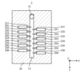
- FIG. 8 is a sectional view taken along the line VI-VI in FIG. 3, and is a diagram showing the configuration of the temperature difference generating section 5A.
- FIG. 9 is a cross-sectional view taken along line VII-VII in FIG. 3, and is a diagram showing the configuration of the temperature difference generating section 5B.
- the temperature difference generation units 5A and 5B are, for example, heat generating members. As shown in FIG. 3, the temperature difference generating sections 5A and 5B are attached to the outer surface of the housing section 11 via adhesive layers 14a and 14b so as to sandwich the common ink chamber 13 therebetween.
- the temperature difference generation section 5A will be referred to as the "left side temperature difference generation section 5A”
- the temperature difference generation section 5B will be referred to as the "right side temperature difference generation section 5B”.
- the left side temperature difference generating section 5A and the right side temperature difference generating section 5B extend in the Y-axis direction. Therefore, the temperature difference generating section 5A generates heat, thereby heating the ink supplied to the left pressure chambers 241 to 246 via the left branch channels 221 to 226. Further, as the right temperature difference generating section 5B generates heat, the ink supplied to the right pressure chambers 251 to 256 via the right branch channels 231 to 236 is heated.
- the left side temperature difference generating section 5A includes a left side heating resistor 51a and a left side terminal 52a.
- a temperature control section (not shown) is connected to the left terminal 52a, and when a voltage is applied to the left heating resistor 51a via the left terminal 52a, the left heating resistor 51a generates heat.
- the right side temperature difference generating section 5B includes a right side heating resistor 51b and a right side terminal 52b.
- the above-mentioned temperature control unit is connected to the right terminal 52b, and when a voltage is applied to the right heating resistor 51b via the right terminal 52b, the right heating resistor 51b generates heat.
- the temperature control section controls the amount of heat generated by the left heating resistor 51a and the right heating resistor 51b by varying the applied voltage.
- the left side temperature difference generating section 5A and the right side temperature difference generating section 5B cancel out pressure waves generated in the left side pressure chambers 241 to 246 due to ink ejection and pressure waves generated in the right side pressure chambers 251 to 256. It has the function of producing a thermal effect. The details will be explained below.
- the wiring density per unit area of the left heating resistor 51a (hereinafter simply referred to as "wiring density") is the wiring density of the right heating resistor 51b. It's different.
- the wiring density of the left side temperature difference generating section 5A is higher than the wiring density of the right side temperature difference generating section 5B. Therefore, when the temperature control section applies the same voltage to the left temperature difference generation section 5A and the right temperature difference generation section 5B, the amount of heat generated by the left temperature difference generation section 5A is larger than that of the right temperature difference generation section 5B. Become.
- the amount of heat generated by the left heating resistor 51a and the amount of heat generated by the right heating resistor 51b can be changed. A difference may be made between the two.
- a temperature difference occurs at both ends in the X-axis direction within the common ink chamber 13.
- This temperature difference is desirably 0.5°C or more and 20°C or less.
- the temperature of the ink in the space near the left side temperature difference generating section 5A is higher than the ink in the space near the right side temperature difference generating section 5B.
- the ink supplied to the left pressure chambers 241 to 246 via the left branch channels 221 to 226 has a higher temperature than the ink supplied to the right pressure chambers 251 to 256 via the right branch channels 231 to 236.
- the temperature of the ink in the left pressure chambers 241-246 becomes higher than that in the right pressure chambers 251-256.
- the pressure control unit simultaneously applies voltage to the left pressure variation units 31 to 36 and the right pressure variation units 41 to 46.
- pressure waves are generated within the left pressure chambers 241 to 246 and the right pressure chambers 251 to 256.
- These pressure waves have a phase that depends on the temperature of the ink. That is, the pressure waves generated in the left pressure chambers 241 to 246 and the pressure waves generated in the right pressure chambers 251 to 256 have different phases from each other.
- vibrations of ink within the common ink chamber 13 are suppressed, and in turn, vibrations of ink propagated from the common ink chamber 13 to the left pressure chambers 241 to 246 and the right pressure chambers 251 to 256 are suppressed.
- the inkjet head 1 has a pressure chamber 241 and a right pressure chamber 251 in which internal ink pressure fluctuations propagate to each other.
- the main body 2 includes a left nozzle 411 and a right nozzle 421.
- the inkjet head 1 also includes a left pressure variation section 31 that varies the pressure of ink in the left pressure chamber 241 and ejects the ink through the left nozzle 411, and a left pressure variation section 31 that varies the pressure of ink in the right pressure chamber 251.
- a right pressure variation section 41 that discharges ink through a right pressure chamber 251 is provided.
- the inkjet head 1 includes a left side temperature difference generating section 5A and a right side temperature difference generating section 5B that generate a thermal effect so that the pressure waves generated in the left side pressure chamber 241 and the pressure waves generated in the right side pressure chamber 251 cancel each other out. Equipped with.
- the left side temperature difference generation unit 5A and the right side temperature difference generation unit 5B generate a thermal effect so that a temperature difference is generated between the ink in the left pressure chamber 241 and the ink in the right pressure chamber 251.
- the main body portion 2 includes a plurality of left pressure chambers 241 to 246, a plurality of right pressure chambers 251 to 256, and a common ink chamber 13. Further, the plurality of left pressure chambers 241 to 246 are arranged along the extending direction (Y-axis direction) of the common ink chamber 13. The plurality of right pressure chambers 251 to 256 are arranged to sandwich the common ink chamber 13 together with the plurality of left pressure chambers 241 to 246, and are arranged along the extending direction of the common ink chamber 13.
- inkjet head 1 having a plurality of nozzle rows, pressure waves caused by ink ejection through the nozzles in one nozzle row and pressure waves caused by ink ejection through the nozzles in another nozzle row are canceled out. Can be matched. Therefore, the influence of ink ejection through different nozzle rows can be suppressed, so ink can be normally ejected through a plurality of nozzle rows.
- the left side temperature difference generating section 5A and the right side temperature difference generating section 5B supply ink from the common ink chamber 13 to the plurality of left side pressure chambers 241 to 246, and from the common ink chamber 13 to the plurality of right side pressure chambers 251 to 256. This creates a temperature difference between the ink and the ink.
- the left side temperature difference generating section 5A has a left side heating resistor 51a that heats the ink supplied from the common ink chamber 13 to the plurality of left side pressure chambers 241 to 246.
- the right side temperature difference generating section 5B has a right side heating resistor 51b that heats the ink supplied from the common ink chamber 13 to the right side pressure chambers 251 to 256, and the right side heating resistor 51b is connected to the left side heating resistor 51a. It also has a low calorific value.
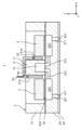
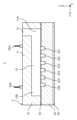
- FIG. 10 is a vertical cross-sectional view illustrating the inkjet head 1 according to Modification 1, and is a vertical cross-sectional view showing the ink flow path from the common ink chamber 13 to the left nozzle 411 and the right nozzle 421.
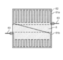
- FIG. 11 is a diagram illustrating the temperature difference generation unit 6 according to Modification 1.
- the inkjet head 1 according to the first modification includes one temperature difference generation section 6 instead of the left side temperature difference generation section 5A and the right side temperature difference generation section 5B.
- the temperature difference generating section 6 is attached via an adhesive layer 14c so as to cover the upper surface and outer surface of the housing section 11.
- the temperature difference generation section 6 includes a heating resistor 62 and a terminal 63.
- the heating resistor 62 constitutes a heating section 61a and a heating section 61b. That is, the heat generating part 61a and the heat generating part 61b are integrally formed.
- the heat generating section 61a will be referred to as a "left side heat generating section”
- the heat generating section 61b will be referred to as a "right side heat generating section”.
- the temperature difference generating section 6 is bent, and the left side heat generating section 61a is located on the outer surface of the housing section 11 on the negative side in the X-axis direction, and the right side heat generating section 61b is located on the outer surface of the housing section 11 on the positive side in the X-axis direction. (see FIG. 10).
- the ink supplied from the common ink chamber 13 to the left pressure chambers 241 to 246 is heated by the left side heat generating section 61a, and the ink supplied to the plurality of right pressure chambers 251 to 256 is heated by the right side heat generating section 61b. Ru.
- the wiring density of the heat generating resistor 62 is different between the left side heat generating section 61a and the right side heat generating section 61b.
- the wiring density of the left side heat generating part 61a is greater than the wiring density of the right side heat generating part 61b.
- the amount of heat generated by the left side heat generating section 61a per unit time is greater than the amount of heat generated by the right side heat generating section 61b.
- the temperature difference generation section 6 includes a left side heat generating section 61a that heats the ink supplied from the common ink chamber 13 to the plurality of left pressure chambers 241 to 246, and a
- the right side heat generating section 61b heats the ink supplied to the right side pressure chambers 251 to 256.
- the right side heat generating section 61b is integrally formed with the left side heat generating section 61a, and has a smaller calorific value than the right side heat generating section 61b.
- the same effects as in the first embodiment can be obtained. Moreover, since it is sufficient to dispose one temperature difference generation section 6, the number of terminals connected to the temperature control section can be reduced.
- FIG. 12 is a vertical cross-sectional view illustrating the inkjet head 1 according to Modification 2, and is a vertical cross-sectional view showing the ink flow path from the common ink chamber 13 to the left nozzle 411 and the right nozzle 421.
- the left side temperature difference generation section 5A includes a left side temperature detection section 54a and a left side temperature control section 55a in addition to the left side heating resistor 51a and the left side terminal 52a.
- the right temperature difference generation section 5B includes a right temperature detection section 54b and a right temperature control section 55b in addition to the right heating resistor 51b and the right terminal 52b.
- the left side temperature detection section 54a detects the temperature of the left side temperature difference generation section 5A.
- the left temperature control section 55a controls the voltage applied to the left terminal 52a based on the temperature detected by the left temperature detection section 54a.
- the right temperature detection section 54b detects the temperature of the right temperature difference generation section 5B.
- the right temperature control section 55b controls the voltage applied to the right terminal 52b based on the temperature detected by the right temperature detection section 54b.
- the temperature control section controls the voltage applied to the left side temperature difference generation section 5A and the right side temperature difference generation section 5B. They may be controlled individually.
- the inkjet head 1 includes a left side temperature detection section 54a that detects the temperature of the left side temperature difference generation section 5A, a left side temperature control section 55a that controls the thermal effect based on the temperature detection result, and a right side temperature difference generation section 54a that detects the temperature of the left side temperature difference generation section 5A. It includes a right temperature detection section 54b that detects the temperature of the generation section 5B, and a right temperature control section 55b that controls the thermal effect based on the temperature detection result.
- the difference in calorific value between them it is possible to freely adjust the difference in calorific value between them. For example, when the pressure waves in the common ink chamber 13 cancel each other out and the suppression of vibration of ink in the common ink chamber 13 is small, the difference in the amount of heat generated between the left temperature difference generating section 5A and the right temperature difference generating section 5B can be made larger. Therefore, vibrations of ink within the common ink chamber 13 caused by pressure waves from each pressure chamber can be reliably suppressed. Therefore, it is possible to more reliably suppress the influence of ink ejected through different nozzles.
- the inkjet head 1 according to the third modification includes the left side temperature difference generating section 5A, but does not include the right side temperature difference generating section 5B. Therefore, the left pressure chambers 241 to 246 are supplied with ink heated by the left temperature difference generating section 5A. On the other hand, ink is supplied from the common ink chamber 13 to the right pressure chambers 251 to 256 without being heated. In this way, a temperature difference is created between the ink in the left pressure chambers 241-246 and the ink in the right pressure chambers 251-256.
- the inkjet head 1 includes the left side temperature difference generating section 5A, and the left side temperature difference generating section 5A supplies the plurality of left side pressure chambers 241 to 246 from the common ink chamber 13. Heat the ink.
- Modification 3 the same effects as in the first embodiment can be obtained. Furthermore, since it is only necessary to arrange one left side temperature difference generating section 5A on one outer surface of the housing section 11, the configuration is simpler than that of the first embodiment, and the influence of ink ejection through different nozzles can be reduced. This can be suppressed more reliably.
- FIG. 13 is a vertical cross-sectional view illustrating the inkjet head 1 according to Modification 4, and is a vertical cross-sectional view showing the ink flow path from the common ink chamber 13 to the left nozzle 411 and the right nozzle 421.
- the inkjet head 1 includes a left side temperature difference generation section 7A and a right side temperature difference generation section 7B.
- the left side temperature difference generation section 5A and the right side temperature difference generation section 5B of the first embodiment were attached to the outer surface of the housing section 11, but the left side temperature difference generation section 7A and the right side temperature difference generation section 7B are A section is built into the housing section 11.
- the left side temperature difference generating section 7A includes a left side heating resistor 71a and a left side terminal 72a
- the right side temperature difference generating section 7B includes a right side heating resistor 71b and a right side heating resistor 71b whose calorific value per unit time is smaller than that of the left side heating resistor 71a.
- a terminal 72b is provided.
- the left heating resistor 71a and the right heating resistor 71b are provided so as to be built into the housing portion 11.
- the same effects as the first embodiment can be obtained. Furthermore, it is possible to reduce the effort required to attach the left side temperature difference generation section 7A and the right side temperature difference generation section 7B, such as by pasting them with adhesive or the like.
- FIG. 14 is a vertical cross-sectional view illustrating the inkjet head 1 according to the second embodiment, and is a vertical cross-sectional view showing the ink flow path from the common ink chamber 13 to the left nozzle 411 and the right nozzle 421.
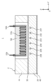
- FIG. 15 is a longitudinal cross-sectional view illustrating the inkjet head 1, and is a diagram showing the configuration of the left side temperature difference generation section 8A.
- the inkjet head 1 includes a left side temperature difference generating section 8A and a right side temperature difference generating section 8B in place of the left side temperature difference generating section 5A and the right side temperature difference generating section 5B.
- the left side temperature difference generating section 5A and the right side temperature difference generating section 5B of the first embodiment had substantially uniform heat generation amount in the Y-axis direction, but the left side temperature difference generating section 8A and the right side temperature difference generating section of the present embodiment
- the portion 8B has a different amount of heat generated in the Y-axis direction.
- the left side temperature difference generating section 8A and the right side temperature difference generating section 8B have the same configuration, and each includes a heating resistor 81a and a terminal 82a.
- the heating resistor 81a has a dense portion 81c where the heating resistors 81a are densely packed, and a sparse portion 81d where the heating resistors 81a are not densely packed.
- the sparse portions 81d are arranged alternately along the Y-axis direction.
- the heating resistor 81a has two or more dense portions 81c and two or more sparse portions 81d.
- the dense portions 81c and the sparse portions 81d of the left side temperature difference generating section 8A are formed so as to correspond alternately to positions corresponding to the left branch channels 221 to 226.
- the dense portions 81c and sparse portions 81d of the right temperature difference generating section 8B are formed to be alternately arranged at positions corresponding to the right branch channels 231 to 236.
- the wiring density in the dense area 81c is higher than that in the sparse area 81d, so when a voltage is applied through the terminal 82a, the amount of heat generated in the dense area 81c is greater than the amount of heat generated in the sparse area 81d. .
- the amount of heat generated in the dense portion 81c is desirably about 101% or more and 300% or less than the amount of heat generated in the sparse portion 81d.
- a temperature difference occurs in the ink supplied from the common ink chamber 13 to the left side pressure chambers 241 to 246 via the left side branch channels 221 to 226.
- the temperatures of the ink in the left pressure chambers 241 and 242 adjacent to each other in the Y-axis direction are different from each other.
- a temperature difference occurs in the ink supplied to the right pressure chambers 251 to 256 via the right branch channels 231 to 236.
- ink in the left pressure chambers 242, 244, 246 connected to the left branch channels 222, 224, 226, respectively is ink in the left pressure chambers 241, 243, 245 connected to the left branch channels 221, 223, 225, respectively.
- the temperature is higher than that of ink.
- the plurality of pressure waves generated in the left pressure chambers 241 to 246 include pressure waves having mutually different phases.
- the plurality of pressure waves generated in the right pressure chambers 251 to 256 include pressure waves having mutually different phases.
- the main body 2 includes left pressure chambers 241 to 246 and a common ink chamber 13 connected to the left pressure chambers 241 to 246. They are arranged in the extending direction of the ink chamber 13.
- the left side temperature difference generation unit 8A changes the temperature of the ink supplied from the common ink chamber 13 to the plurality of left side pressure chambers 241 to 246, depending on the position of the common ink chamber 13 in the extending direction.
- FIG. 16 is a longitudinal cross-sectional view illustrating the inkjet head 1 according to Modification 5, and is a diagram showing the configuration of the temperature difference generation section 9A.
- FIG. 17 is a vertical cross-sectional view illustrating an inkjet head 1 according to modification 5, and is a vertical cross-sectional view showing the common ink chamber 13.
- FIG. 13A and 13B in FIG. 17 are the negative end and positive end of the common ink chamber 13 in the Y-axis direction, respectively. Note that the ink at the negative end 13A and the positive end 13B is not heated.
- the inkjet head 1 according to Modification 5 includes two temperature difference generation units 9A instead of the left side temperature difference generation unit 8A and the right side temperature difference generation unit 8B.
- the temperature difference generation section 9A has a different wiring distribution in the Y-axis direction compared to the left side temperature difference generation section 8A and the right side temperature difference generation section 8B of the second embodiment.
- the temperature difference generating section 9A includes a heating resistor 91a and a terminal 92a.
- the heating resistor 91a is arranged such that the dense portion 91c where the heating resistor 91a is densely arranged is located at both ends in the Y-axis direction, and the sparse portion 91d where the heating resistor 91a is not densely arranged is located at the center portion in the Y-axis direction. It is composed of Therefore, in the Y-axis direction, the amount of heat generated at both ends is greater than the amount of heat generated at the center.
- ink supplied to the left pressure chambers 241, 242, 245, 246 via the left branch channels 221, 222, 225, 226 is supplied to the left pressure chambers 243, 244 via the left branch channels 223, 224.
- the temperature will be higher than that of the ink being supplied.
- the ink supplied to the right pressure chambers 251, 252, 255, 256 via the right branch channels 231, 232, 235, 236 is supplied to the right pressure chambers 253, 254 via the right branch channels 233, 234.
- the temperature will be higher than that of the ink.
- the pressure generated in the left pressure chambers 241, 242, 245, 246 and the right pressure chambers 251, 252, 255, 256 which are arranged at both ends in the Y-axis direction and store relatively high-temperature ink.
- the waves propagate to the common ink chamber 13.
- These pressure waves propagate to the negative end 13A and positive end 13B of the common ink chamber 13, a phase change occurs.
- the magnitude of the phase change is larger than that in the case where the ink temperature in the pressure chamber located at the center in the Y-axis direction is made higher than the ink temperature in the pressure chambers at both ends.
- the effect of canceling out the pressure waves from each pressure chamber can be further strengthened, and the vibration of the ink within the common ink chamber 13 can be further suppressed.
- the temperature difference generating section 9A is supplied to the left pressure chambers 241 and 246 via at least two left branch channels 221 and 226 located at both ends of the common ink chamber 13 in the extending direction.
- the temperature of the ink is made higher than the temperature of the ink supplied to the left pressure chambers 243, 244 via the left branch channels 223, 224 located in the center.
- the effect of canceling out the pressure waves propagating from the left pressure chambers 241 to 246 can be further strengthened, and the vibration of the ink in the common ink chamber 13 can be further suppressed.
- the temperature difference generating section is described as being a heat generating member, but it may be a heat absorbing member such as a Peltier element. Further, the temperature difference generating section may be a combination of a heat generating member and a heat absorbing member.
- the plurality of pressure chambers to which ink is supplied from the common ink chamber do not necessarily have to be arranged on both sides of the common ink chamber. That is, on one side of the common ink chamber 13, a plurality of pressure chambers to which ink is supplied from the common ink chamber may be arranged. In that case, the second embodiment and modification 5 may be applied.
- the inkjet head of the present disclosure can be applied to an inkjet head in which at least two pressure chambers and two nozzles are formed in which pressure waves generated internally propagate to each other.
- the two pressure chambers may be arranged to sandwich the common ink chamber 13, or may be arranged on one side of the common ink chamber 13 (for example, on the negative side in the X-axis direction).
- an inkjet head that suppresses the influence of ink ejection through one nozzle and ink ejection through another nozzle.
- the present disclosure can be suitably applied to an inkjet head that has a plurality of pressure chambers in which internal ink pressure fluctuations propagate to each other and ejects ink through a plurality of nozzles.
Landscapes
- Particle Formation And Scattering Control In Inkjet Printers (AREA)
- Ink Jet (AREA)
Priority Applications (2)
| Application Number | Priority Date | Filing Date | Title |
|---|---|---|---|
| KR1020257001807A KR20250039368A (ko) | 2022-07-22 | 2023-06-20 | 잉크젯 헤드 |
| JP2024534976A JPWO2024018801A1 (https=) | 2022-07-22 | 2023-06-20 |
Applications Claiming Priority (2)
| Application Number | Priority Date | Filing Date | Title |
|---|---|---|---|
| JP2022-117362 | 2022-07-22 | ||
| JP2022117362 | 2022-07-22 |
Publications (1)
| Publication Number | Publication Date |
|---|---|
| WO2024018801A1 true WO2024018801A1 (ja) | 2024-01-25 |
Family
ID=89617617
Family Applications (1)
| Application Number | Title | Priority Date | Filing Date |
|---|---|---|---|
| PCT/JP2023/022807 Ceased WO2024018801A1 (ja) | 2022-07-22 | 2023-06-20 | インクジェットヘッド |
Country Status (4)
| Country | Link |
|---|---|
| JP (1) | JPWO2024018801A1 (https=) |
| KR (1) | KR20250039368A (https=) |
| TW (1) | TW202417260A (https=) |
| WO (1) | WO2024018801A1 (https=) |
Citations (7)
| Publication number | Priority date | Publication date | Assignee | Title |
|---|---|---|---|---|
| JP2002211011A (ja) * | 2001-01-17 | 2002-07-31 | Ricoh Co Ltd | インクジェット記録装置及びプリンタドライバ |
| JP2006240262A (ja) * | 2005-03-07 | 2006-09-14 | Fuji Photo Film Co Ltd | 液体吐出ヘッド及び画像形成装置 |
| JP2011230046A (ja) * | 2010-04-27 | 2011-11-17 | Canon Inc | 液体吐出装置 |
| JP2013154561A (ja) * | 2012-01-31 | 2013-08-15 | Brother Industries Ltd | 液滴吐出装置 |
| JP2014104714A (ja) * | 2012-11-29 | 2014-06-09 | Kyocera Corp | 液体吐出ヘッド、およびそれを用いた記録装置 |
| CN110549747A (zh) * | 2019-09-09 | 2019-12-10 | 昆山国显光电有限公司 | 一种喷墨打印装置以及制备薄膜的方法 |
| JP2020055153A (ja) * | 2018-09-28 | 2020-04-09 | ブラザー工業株式会社 | 液体吐出装置 |
Family Cites Families (1)
| Publication number | Priority date | Publication date | Assignee | Title |
|---|---|---|---|---|
| JP2016159514A (ja) | 2015-03-02 | 2016-09-05 | 富士フイルム株式会社 | 液体吐出装置、及び液体吐出ヘッドの異物排出方法 |
-
2023
- 2023-06-20 JP JP2024534976A patent/JPWO2024018801A1/ja active Pending
- 2023-06-20 KR KR1020257001807A patent/KR20250039368A/ko active Pending
- 2023-06-20 WO PCT/JP2023/022807 patent/WO2024018801A1/ja not_active Ceased
- 2023-07-04 TW TW112124908A patent/TW202417260A/zh unknown
Patent Citations (7)
| Publication number | Priority date | Publication date | Assignee | Title |
|---|---|---|---|---|
| JP2002211011A (ja) * | 2001-01-17 | 2002-07-31 | Ricoh Co Ltd | インクジェット記録装置及びプリンタドライバ |
| JP2006240262A (ja) * | 2005-03-07 | 2006-09-14 | Fuji Photo Film Co Ltd | 液体吐出ヘッド及び画像形成装置 |
| JP2011230046A (ja) * | 2010-04-27 | 2011-11-17 | Canon Inc | 液体吐出装置 |
| JP2013154561A (ja) * | 2012-01-31 | 2013-08-15 | Brother Industries Ltd | 液滴吐出装置 |
| JP2014104714A (ja) * | 2012-11-29 | 2014-06-09 | Kyocera Corp | 液体吐出ヘッド、およびそれを用いた記録装置 |
| JP2020055153A (ja) * | 2018-09-28 | 2020-04-09 | ブラザー工業株式会社 | 液体吐出装置 |
| CN110549747A (zh) * | 2019-09-09 | 2019-12-10 | 昆山国显光电有限公司 | 一种喷墨打印装置以及制备薄膜的方法 |
Also Published As
| Publication number | Publication date |
|---|---|
| TW202417260A (zh) | 2024-05-01 |
| JPWO2024018801A1 (https=) | 2024-01-25 |
| KR20250039368A (ko) | 2025-03-20 |
Similar Documents
| Publication | Publication Date | Title |
|---|---|---|
| JP5688140B2 (ja) | 同一平面上の電極を有した圧電アクチュエータ | |
| JP5741101B2 (ja) | 液体噴射ヘッド、液体噴射装置及び液体噴射装置の製造方法 | |
| CN100393516C (zh) | 喷墨打印机的喷墨头 | |
| JP7172044B2 (ja) | 液体吐出ヘッド、液体吐出装置、圧電デバイス、および超音波センサー | |
| JP5899928B2 (ja) | インクジェットヘッド | |
| JP6201527B2 (ja) | インクジェットヘッド | |
| JP4826732B2 (ja) | 液滴噴射装置 | |
| WO2024018801A1 (ja) | インクジェットヘッド | |
| CN113696631A (zh) | 液体喷出头及液体喷出装置 | |
| JP3231523B2 (ja) | オンデマンド型インクジェットヘッド | |
| JP4453965B2 (ja) | インクジェット記録ヘッド、および記録装置 | |
| JP4269608B2 (ja) | インクジェットヘッドおよびそれを備えたインクジェット式記録装置 | |
| JP2004160915A (ja) | 液滴噴射装置およびその製造方法 | |
| JP2005111810A (ja) | 液体吐出装置 | |
| JP4450160B2 (ja) | インクジェットプリンタヘッド | |
| JP4754775B2 (ja) | インクジェットプリンタヘッド | |
| JP4876487B2 (ja) | インクジェットヘッド及びその製造方法 | |
| JP3931972B2 (ja) | インクジェットプリンタヘッド | |
| JP7792625B2 (ja) | インクジェットヘッド | |
| JP7718256B2 (ja) | 液体吐出ヘッド、及び液体吐出装置 | |
| TW202404823A (zh) | 噴墨頭 | |
| JPH10138471A (ja) | インクジェットヘッド | |
| JP2000071449A (ja) | インクジェットヘッド及びインクジェット記録装置 | |
| JP2004291543A (ja) | インクジェットプリンタヘッド | |
| JP2715969B2 (ja) | インクジェットプリントヘッド |
Legal Events
| Date | Code | Title | Description |
|---|---|---|---|
| 121 | Ep: the epo has been informed by wipo that ep was designated in this application |
Ref document number: 23842732 Country of ref document: EP Kind code of ref document: A1 |
|
| WWE | Wipo information: entry into national phase |
Ref document number: 2024534976 Country of ref document: JP |
|
| NENP | Non-entry into the national phase |
Ref country code: DE |
|
| WWP | Wipo information: published in national office |
Ref document number: 1020257001807 Country of ref document: KR |
|
| 122 | Ep: pct application non-entry in european phase |
Ref document number: 23842732 Country of ref document: EP Kind code of ref document: A1 |