WO2024009439A1 - 経路計画装置及び経路計画方法 - Google Patents
経路計画装置及び経路計画方法 Download PDFInfo
- Publication number
- WO2024009439A1 WO2024009439A1 PCT/JP2022/026868 JP2022026868W WO2024009439A1 WO 2024009439 A1 WO2024009439 A1 WO 2024009439A1 JP 2022026868 W JP2022026868 W JP 2022026868W WO 2024009439 A1 WO2024009439 A1 WO 2024009439A1
- Authority
- WO
- WIPO (PCT)
- Prior art keywords
- route
- coordinates
- heavy equipment
- erected
- planning
- Prior art date
- Legal status (The legal status is an assumption and is not a legal conclusion. Google has not performed a legal analysis and makes no representation as to the accuracy of the status listed.)
- Ceased
Links
Images


Classifications
-
- E—FIXED CONSTRUCTIONS
- E04—BUILDING
- E04H—BUILDINGS OR LIKE STRUCTURES FOR PARTICULAR PURPOSES; SWIMMING OR SPLASH BATHS OR POOLS; MASTS; FENCING; TENTS OR CANOPIES, IN GENERAL
- E04H12/00—Towers; Masts or poles; Chimney stacks; Water-towers; Methods of erecting such structures
-
- E—FIXED CONSTRUCTIONS
- E21—EARTH OR ROCK DRILLING; MINING
- E21B—EARTH OR ROCK DRILLING; OBTAINING OIL, GAS, WATER, SOLUBLE OR MELTABLE MATERIALS OR A SLURRY OF MINERALS FROM WELLS
- E21B7/00—Special methods or apparatus for drilling
-
- G—PHYSICS
- G06—COMPUTING OR CALCULATING; COUNTING
- G06Q—INFORMATION AND COMMUNICATION TECHNOLOGY [ICT] SPECIALLY ADAPTED FOR ADMINISTRATIVE, COMMERCIAL, FINANCIAL, MANAGERIAL OR SUPERVISORY PURPOSES; SYSTEMS OR METHODS SPECIALLY ADAPTED FOR ADMINISTRATIVE, COMMERCIAL, FINANCIAL, MANAGERIAL OR SUPERVISORY PURPOSES, NOT OTHERWISE PROVIDED FOR
- G06Q50/00—Information and communication technology [ICT] specially adapted for implementation of business processes of specific business sectors, e.g. utilities or tourism
- G06Q50/08—Construction
Definitions
- the present disclosure relates to a route planning device and a route planning method that generate a route plan for heavy machinery that performs utility pole construction.
- Utility pole construction is carried out by operators operating heavy machinery.
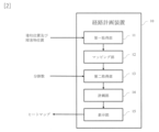
- the related work procedure is shown in Figure 1.
- workers conduct a site survey to understand the location of obstacles and the position where the utility pole will be erected (pole position) (51), and then, based on the site survey, determine how to operate the heavy equipment. I was making a plan (52).
- the worker instructed the heavy equipment operator to operate the heavy equipment (53), and the operator operated the heavy equipment according to the worker's instructions (54).
- An object of the present disclosure is to provide a route planning device and a route planning method that can present efficient placement of heavy equipment and utility poles to workers without relying on the skills of the workers.
- a combination of coordinates for arranging heavy equipment and coordinates for laying down utility poles to be erected on a map near the work site is converted into points, and a heat map is displayed for each coordinate for arranging heavy equipment. And so.
- this disclosure provides: a first acquisition unit that acquires the position of the pillar and the position of the obstacle; a mapping unit that applies the acquired pillar erected position and the obstacle position to a map in the vicinity of the work place, and sets a work area of a predetermined size centered on a position a predetermined distance from the acquired pillar erected position; a second acquisition unit that acquires the number of divisions into which the work area is divided; A combination of all the coordinates for arranging heavy equipment and all the coordinates for laying down utility poles to be erected in the work area divided according to the number of divisions acquired by the second acquisition unit, the construction of poles is determined from the coordinates for arranging heavy equipment.
- This is a route planning device comprising:
- the planning unit ranks the route with a high probability of search success in the generated route plan, ranks the route with a short route travel time highly, and scores the route based on efficiency based on the two ranks. It is characterized by
- the first acquisition unit further acquires the size of the heavy equipment and the size of the utility pole
- the planning unit is characterized in that it generates a route plan in consideration of the size of the heavy equipment and the size of the utility pole.
- This disclosure further comprising a sensor unit that scans the obstacle position,
- the first acquisition unit is characterized in that the first acquisition unit acquires the obstacle position from the sensor unit.
- the route planning device a first acquisition step of acquiring the position of the pillar and the position of the obstacle; a mapping step of applying the acquired pillar erecting position and the obstacle position to a map of the vicinity of the work place, and setting a work area of a predetermined size centered on a position a predetermined distance from the acquired pillar erecting position; a second acquisition step of acquiring the number of divisions into which the work area is divided; A combination of all the coordinates for arranging heavy machinery and all the coordinates for laying down the utility poles to be erected in the work area divided according to the number of divisions obtained in the second acquisition step, from the coordinates for arranging the heavy equipment to the poles to be erected.
- the route with a high search success probability is ranked highly
- the route with a short route travel time is ranked highly
- points are scored based on the efficiency based on the two ranks. It is characterized by
- the size of the heavy equipment and the size of the utility pole are further acquired
- a route plan is generated taking into consideration the size of the heavy equipment and the size of the utility pole.
- this disclosure provides: A program for causing a computer to function as the route planning device according to claim 1.
- FIG. 1 is a diagram illustrating the configuration of a route planning device according to the present disclosure.
- FIG. 2 is a diagram illustrating the operation of the route planning device of the present disclosure. It is a figure explaining the map to which the pillar erected position and the obstacle position were applied.
- FIG. 2 is a diagram illustrating a map in which work areas are set.
- FIG. 3 is a diagram illustrating a map in which a work area is divided.
- FIG. 2 is a diagram illustrating a map specifying coordinates for arranging heavy machinery.
- FIG. 2 is a diagram illustrating a map specifying the coordinates for laying down utility poles to be erected.
- FIG. 3 is a diagram showing search success probability and route travel time. It is a figure in which search success probability and route travel time are aggregated and converted into points. It is a diagram visualizing the points for the coordinates where the utility pole is laid down.
- FIG. 3 is a diagram showing a heat map display.
- the route planning device 10 includes a first acquisition unit 11 that acquires the pillar erected positions and obstacle positions, and a first acquisition unit 11 that acquires the pillar erected positions and obstacle positions, and applies the acquired pillar erected positions and obstacle positions to a map in the vicinity of the work place, and the acquired pillar erected positions.
- a mapping unit 12 that sets a work area of a predetermined size centered on a position a predetermined distance away from a location
- a second acquisition unit 13 that acquires the number of divisions into which the work area is to be divided, and a division acquired by the second acquisition unit.
- the poles are erected from the coordinates for placing the heavy equipment via the coordinates for laying down the utility poles to be erected.
- a planning unit 14 that generates a route plan to a location, aggregates the search success probability and route travel time in each route plan and converts it into a score, and a display that displays a heat map of the aggregated score for each coordinate where the heavy equipment is placed. 15.
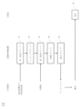
- FIG. 3 shows the operation of the route planning device of the present disclosure.
- the operation of the route planning device of the present disclosure includes a first acquisition step 21, a mapping step 22, a second acquisition step 23, a planning step 24, and a display step 25. This will be explained below with reference to FIGS. 2 and 3.
- the worker inputs the location of the utility pole in the work area, and the location of obstacles such as existing obstacles and utility pole equipment.
- the first acquisition unit 11 of the route planning device 10 acquires the input pillar positions and obstacle positions.
- the route planning device 10 may acquire the obstacle position from a sensor unit (not shown) external to the route planning device 10 that scans the work place.
- the route planning device 10 may also include a sensor section (not shown) that scans the work place, and the sensor section may scan the position of an obstacle.
- the first acquisition unit 11 acquires the obstacle position from the sensor unit. If the sensor section scans the obstacle position, the obstacle position can be acquired without human intervention.
- the first acquisition unit may further acquire the size of the heavy equipment and the size of the utility pole to be laid down. When searching for a route, it is possible to accurately calculate the locations through which heavy equipment can pass.
- mapping step The mapping unit 12 of the route planning device 10 applies the acquired pillar positions and obstacle positions to a map of the vicinity of the work site.
- Figure 4 shows a map showing the positions of pillars and obstacles.
- 31 is an obstacle position
- 32 is a pillar erection position.
- an existing utility pole is present at an obstacle position 31 marked with a black circle
- an existing electric wire is present at an obstacle position 31 indicated by a broken line.
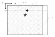
- FIG. 5 shows a map with work areas set.
- a work area 33 is set compared to FIG. 4.
- the center of the work area 33 is a predetermined distance away from the acquired pole erection position 32.
- the work area 33 is 30 m square
- the longitudinal direction of the existing electric wire is the X axis
- the center of the work area is 10 m from the pole erection position 32 in the Y axis direction.
- the worker inputs the number of divisions into which the work area is to be divided.
- the second acquisition unit 13 acquires the input division number.
- the planning unit 14 divides the work area into a matrix, as shown in FIG. 6, according to the number of divisions acquired by the second acquisition unit 13.
- the planning unit 14 specifies coordinates 34 where the heavy equipment is to be placed, as shown in FIG. It is preferable to use the tip of the heavy machinery as the coordinates of the heavy machinery.
- the planning unit 14 specifies the coordinates 35 at which the utility pole to be erected will lie, as shown in FIG.
- a route plan is generated from the coordinates 34 where the heavy equipment is placed to the position 32 where the utility pole is to be erected via the coordinates 35 where the utility pole is laid down.
- a route plan is generated by combining all the coordinates for placing heavy equipment and all the coordinates for laying down utility poles in the divided work area, and the search success probability and route travel time for each route plan are calculated. As shown in FIG. 9, the search success probability and route travel time are obtained for each coordinate where heavy machinery is placed and all coordinates where utility poles to be erected are laid down.
- RRT Rapidly Exploring Random Tree
- RRT* Rapidly Exploring Random Tree Star
- the search success probability is calculated by dividing the number of successful route searches by the number of route search attempts on the route from the coordinates where the heavy equipment is placed to the position where the utility pole is to be erected.
- the percentage of Examples of route search failures include failure to reach the position from the coordinates for placing heavy equipment to the coordinates for laying down the utility pole to be erected within the preset calculation time, or due to obstacles.
- the route may be closed.
- the number of searches is set in advance.
- Route travel time refers to the time required for heavy equipment to depart from the coordinates where the heavy equipment is placed, go through the coordinates where the utility pole to be erected is laid down, and reach the position where the pole is to be erected. is the relative speed divided by .
- the median value of the searched minutes may be used as the route travel time.
- the average value of the searched portion may be used as the route travel time.
- the first acquisition unit 11 acquires the size of heavy machinery and the size of utility poles, it is possible to search for a route with respect to obstacles taking these sizes into consideration.
- the size of heavy machinery include the overall length, width, and length of the arm that grips the utility pole.
- the size of a utility pole is determined by its length in the long axis direction. The route from the coordinates where the heavy equipment will be placed to the coordinates where the utility pole will be erected will take into account only the size of the heavy equipment, and the route from the coordinates where the utility pole will be laid down to the position where the pole will be erected will take into consideration the size of the heavy equipment and the size of the utility pole. good.
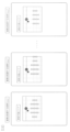
- the planning unit 14 aggregates the search success probability and route travel time in each generated route plan and converts it into a score.
- FIG. 10 shows an example of aggregating and scoring.
- the search success probabilities (Success Probability of Pass Planning) are ranked in five stages from 0 to 4, and routes with high search success probabilities are ranked high and routes with low search success probabilities are ranked low.
- the route execution time is ranked in four stages from 1 to 4, and routes with short route travel times are ranked high and routes with long route travel times are ranked low.
- the product of the rank of search success probability and the rank of route travel time is calculated, and a score is given for each combination of the coordinates where heavy equipment is placed and the coordinates where utility poles are laid down.
- the display unit 15 displays a heat map of the scores aggregated for each coordinate (square mark) where the heavy equipment is placed.
- FIG. 12 An example of a heat map display is shown in FIG. In FIG. 12, the scores are 16, 12, and 9 in descending order of score. Only combinations that have good scores above a certain level may be heat mapped. For example, as shown in FIG. 12, the score is 9 or more.
- the route planning device of the present disclosure can also be realized by a computer and a program, and the program that causes the computer to function as the route planning device can be recorded on a recording medium or provided through a network.
- This disclosure can be applied to various industries including the information and communication industry.
Landscapes
- Engineering & Computer Science (AREA)
- Business, Economics & Management (AREA)
- Life Sciences & Earth Sciences (AREA)
- Architecture (AREA)
- Physics & Mathematics (AREA)
- Geology (AREA)
- Mining & Mineral Resources (AREA)
- General Health & Medical Sciences (AREA)
- Strategic Management (AREA)
- General Life Sciences & Earth Sciences (AREA)
- Health & Medical Sciences (AREA)
- Economics (AREA)
- Fluid Mechanics (AREA)
- Human Resources & Organizations (AREA)
- Marketing (AREA)
- Primary Health Care (AREA)
- Geochemistry & Mineralogy (AREA)
- Tourism & Hospitality (AREA)
- General Business, Economics & Management (AREA)
- General Physics & Mathematics (AREA)
- Theoretical Computer Science (AREA)
- Environmental & Geological Engineering (AREA)
- Civil Engineering (AREA)
- Structural Engineering (AREA)
- Conveying And Assembling Of Building Elements In Situ (AREA)
Priority Applications (3)
| Application Number | Priority Date | Filing Date | Title |
|---|---|---|---|
| PCT/JP2022/026868 WO2024009439A1 (ja) | 2022-07-06 | 2022-07-06 | 経路計画装置及び経路計画方法 |
| JP2024531909A JPWO2024009537A1 (https=) | 2022-07-06 | 2023-01-18 | |
| PCT/JP2023/001347 WO2024009537A1 (ja) | 2022-07-06 | 2023-01-18 | 経路計画装置及び経路計画方法 |
Applications Claiming Priority (1)
| Application Number | Priority Date | Filing Date | Title |
|---|---|---|---|
| PCT/JP2022/026868 WO2024009439A1 (ja) | 2022-07-06 | 2022-07-06 | 経路計画装置及び経路計画方法 |
Publications (1)
| Publication Number | Publication Date |
|---|---|
| WO2024009439A1 true WO2024009439A1 (ja) | 2024-01-11 |
Family
ID=89453058
Family Applications (2)
| Application Number | Title | Priority Date | Filing Date |
|---|---|---|---|
| PCT/JP2022/026868 Ceased WO2024009439A1 (ja) | 2022-07-06 | 2022-07-06 | 経路計画装置及び経路計画方法 |
| PCT/JP2023/001347 Ceased WO2024009537A1 (ja) | 2022-07-06 | 2023-01-18 | 経路計画装置及び経路計画方法 |
Family Applications After (1)
| Application Number | Title | Priority Date | Filing Date |
|---|---|---|---|
| PCT/JP2023/001347 Ceased WO2024009537A1 (ja) | 2022-07-06 | 2023-01-18 | 経路計画装置及び経路計画方法 |
Country Status (2)
| Country | Link |
|---|---|
| JP (1) | JPWO2024009537A1 (https=) |
| WO (2) | WO2024009439A1 (https=) |
Cited By (1)
| Publication number | Priority date | Publication date | Assignee | Title |
|---|---|---|---|---|
| CN119131627A (zh) * | 2024-08-28 | 2024-12-13 | 广东电网有限责任公司揭阳惠来供电局 | 一种基于无人机拍摄图像的配电网线路规划设计方法及系统 |
Citations (4)
| Publication number | Priority date | Publication date | Assignee | Title |
|---|---|---|---|---|
| JP2008217066A (ja) * | 2007-02-28 | 2008-09-18 | Lexer Research Inc | 作業計画立案支援システム |
| JP2010146456A (ja) * | 2008-12-22 | 2010-07-01 | Chugoku Electric Power Co Inc:The | 移設対象支持物の総合移設状況進捗管理システムおよび方法 |
| JP2016132538A (ja) * | 2015-01-20 | 2016-07-25 | 株式会社日立製作所 | 搬入据付け作業計画支援装置および搬入据付け作業計画支援方法 |
| WO2021049112A1 (ja) * | 2019-09-11 | 2021-03-18 | コベルコ建機株式会社 | シミュレーション装置 |
Family Cites Families (5)
| Publication number | Priority date | Publication date | Assignee | Title |
|---|---|---|---|---|
| JPH0724386Y2 (ja) * | 1989-12-20 | 1995-06-05 | 株式会社アイチコーポレーション | 作業車停止位置適正化装置 |
| JPH03271871A (ja) * | 1990-03-20 | 1991-12-03 | Fujitsu Ltd | 線分データ処理方式 |
| JPH0921231A (ja) * | 1995-07-04 | 1997-01-21 | Hitachi Plant Eng & Constr Co Ltd | 作業時間算出方法 |
| JP7132821B2 (ja) * | 2018-10-31 | 2022-09-07 | 株式会社アイチコーポレーション | 作業車の安全装置 |
| JP7423389B2 (ja) * | 2020-04-01 | 2024-01-29 | 東北電力株式会社 | 作業支援装置 |
-
2022
- 2022-07-06 WO PCT/JP2022/026868 patent/WO2024009439A1/ja not_active Ceased
-
2023
- 2023-01-18 WO PCT/JP2023/001347 patent/WO2024009537A1/ja not_active Ceased
- 2023-01-18 JP JP2024531909A patent/JPWO2024009537A1/ja active Pending
Patent Citations (4)
| Publication number | Priority date | Publication date | Assignee | Title |
|---|---|---|---|---|
| JP2008217066A (ja) * | 2007-02-28 | 2008-09-18 | Lexer Research Inc | 作業計画立案支援システム |
| JP2010146456A (ja) * | 2008-12-22 | 2010-07-01 | Chugoku Electric Power Co Inc:The | 移設対象支持物の総合移設状況進捗管理システムおよび方法 |
| JP2016132538A (ja) * | 2015-01-20 | 2016-07-25 | 株式会社日立製作所 | 搬入据付け作業計画支援装置および搬入据付け作業計画支援方法 |
| WO2021049112A1 (ja) * | 2019-09-11 | 2021-03-18 | コベルコ建機株式会社 | シミュレーション装置 |
Cited By (1)
| Publication number | Priority date | Publication date | Assignee | Title |
|---|---|---|---|---|
| CN119131627A (zh) * | 2024-08-28 | 2024-12-13 | 广东电网有限责任公司揭阳惠来供电局 | 一种基于无人机拍摄图像的配电网线路规划设计方法及系统 |
Also Published As
| Publication number | Publication date |
|---|---|
| JPWO2024009537A1 (https=) | 2024-01-11 |
| WO2024009537A1 (ja) | 2024-01-11 |
Similar Documents
| Publication | Publication Date | Title |
|---|---|---|
| KR20200103561A (ko) | 운전 경로 계획 방법, 장치 및 차량 | |
| CN102867074B (zh) | 在建筑物中放置全站仪的方法 | |
| CN112945239B (zh) | 核电厂房三维寻路导航方法及系统 | |
| KR20060002964A (ko) | 윈도우 스택 제어방법, 윈도우 관리 프로그램, 및 윈도우관리장치 | |
| CN113033508B (zh) | 一种基于点云的精细巡检航点快速生成方法 | |
| JP2018031693A (ja) | 架空送電線の離隔評価方法,離隔評価装置,及び離隔評価プログラム、並びに、離隔評価データの表示方法 | |
| JP2004163480A5 (https=) | ||
| WO2024009439A1 (ja) | 経路計画装置及び経路計画方法 | |
| CN108133510A (zh) | 高压输电线路等电位带电作业吊篮法进入模拟系统及方法 | |
| CN110942660B (zh) | 电力作业绝缘斗臂车辅助停车系统及其停车位置搜索方法 | |
| JP2022013830A (ja) | 自律走行車両のためのロードネットワークデータ生成方法、装置およびコンピュータプログラム | |
| CN114754777A (zh) | 一种基于地理坐标系的无人割草车的全路径覆盖规划方法 | |
| CN117573796B (zh) | 一种根据航线自动筛选纸海图的方法及系统 | |
| CN112084288A (zh) | 一种地图可视化管理装置 | |
| JP7768384B2 (ja) | 経路計画装置及び経路計画方法 | |
| AU2022275523A1 (en) | Information processing method and system | |
| KR20200077301A (ko) | Tbm 운용 시뮬레이션 장비 및 이를 이용하여 tbm 기기 운용 능력을 측정하는 방법 | |
| KR20240138854A (ko) | 이동 로봇의 자율 주행을 위한 경로 생성 방법 및 그 장치 | |
| JP2002366709A (ja) | 営巣地探索プログラム、営巣地探索プログラムを記録したコンピュータ読み取り可能な記録媒体、営巣地探索装置および営巣地探索方法 | |
| JPH0694460A (ja) | データ表示装置 | |
| JP4071614B2 (ja) | 測量装置 | |
| JPH11352880A (ja) | 広域地図と道路図面間のデータリンクおよび検索方法と道路図面管理システム | |
| KR102848677B1 (ko) | 자율주행 로봇의 맵 자동 생성 시스템 | |
| JP6149023B2 (ja) | 離隔判定方法、及び、離隔判定プログラム | |
| KR20250036975A (ko) | 두둑 성형 장치, 및 자율 주행 경로 생성 방법 |
Legal Events
| Date | Code | Title | Description |
|---|---|---|---|
| 121 | Ep: the epo has been informed by wipo that ep was designated in this application |
Ref document number: 22950233 Country of ref document: EP Kind code of ref document: A1 |
|
| NENP | Non-entry into the national phase |
Ref country code: DE |
|
| 122 | Ep: pct application non-entry in european phase |
Ref document number: 22950233 Country of ref document: EP Kind code of ref document: A1 |
|
| NENP | Non-entry into the national phase |
Ref country code: JP |