WO2024009439A1 - Route planning device and route planning method - Google Patents
Route planning device and route planning method Download PDFInfo
- Publication number
- WO2024009439A1 WO2024009439A1 PCT/JP2022/026868 JP2022026868W WO2024009439A1 WO 2024009439 A1 WO2024009439 A1 WO 2024009439A1 JP 2022026868 W JP2022026868 W JP 2022026868W WO 2024009439 A1 WO2024009439 A1 WO 2024009439A1
- Authority
- WO
- WIPO (PCT)
- Prior art keywords
- route
- coordinates
- heavy equipment
- erected
- planning
- Prior art date
Links
- 238000000034 method Methods 0.000 title claims description 14
- 238000013507 mapping Methods 0.000 claims abstract description 11
- 238000010276 construction Methods 0.000 claims description 5
- 230000004931 aggregating effect Effects 0.000 claims description 2
- 238000010586 diagram Methods 0.000 description 10
- 238000004891 communication Methods 0.000 description 1
- 239000011159 matrix material Substances 0.000 description 1
- 238000005070 sampling Methods 0.000 description 1
Images


Classifications
-
- E—FIXED CONSTRUCTIONS
- E04—BUILDING
- E04H—BUILDINGS OR LIKE STRUCTURES FOR PARTICULAR PURPOSES; SWIMMING OR SPLASH BATHS OR POOLS; MASTS; FENCING; TENTS OR CANOPIES, IN GENERAL
- E04H12/00—Towers; Masts or poles; Chimney stacks; Water-towers; Methods of erecting such structures
-
- E—FIXED CONSTRUCTIONS
- E21—EARTH DRILLING; MINING
- E21B—EARTH DRILLING, e.g. DEEP DRILLING; OBTAINING OIL, GAS, WATER, SOLUBLE OR MELTABLE MATERIALS OR A SLURRY OF MINERALS FROM WELLS
- E21B7/00—Special methods or apparatus for drilling
-
- G—PHYSICS
- G06—COMPUTING; CALCULATING OR COUNTING
- G06Q—INFORMATION AND COMMUNICATION TECHNOLOGY [ICT] SPECIALLY ADAPTED FOR ADMINISTRATIVE, COMMERCIAL, FINANCIAL, MANAGERIAL OR SUPERVISORY PURPOSES; SYSTEMS OR METHODS SPECIALLY ADAPTED FOR ADMINISTRATIVE, COMMERCIAL, FINANCIAL, MANAGERIAL OR SUPERVISORY PURPOSES, NOT OTHERWISE PROVIDED FOR
- G06Q50/00—Systems or methods specially adapted for specific business sectors, e.g. utilities or tourism
- G06Q50/08—Construction
Definitions
- the present disclosure relates to a route planning device and a route planning method that generate a route plan for heavy machinery that performs utility pole construction.
- Utility pole construction is carried out by operators operating heavy machinery.
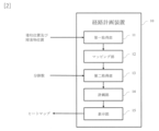
- the related work procedure is shown in Figure 1.
- workers conduct a site survey to understand the location of obstacles and the position where the utility pole will be erected (pole position) (51), and then, based on the site survey, determine how to operate the heavy equipment. I was making a plan (52).
- the worker instructed the heavy equipment operator to operate the heavy equipment (53), and the operator operated the heavy equipment according to the worker's instructions (54).
- An object of the present disclosure is to provide a route planning device and a route planning method that can present efficient placement of heavy equipment and utility poles to workers without relying on the skills of the workers.
- a combination of coordinates for arranging heavy equipment and coordinates for laying down utility poles to be erected on a map near the work site is converted into points, and a heat map is displayed for each coordinate for arranging heavy equipment. And so.
- this disclosure provides: a first acquisition unit that acquires the position of the pillar and the position of the obstacle; a mapping unit that applies the acquired pillar erected position and the obstacle position to a map in the vicinity of the work place, and sets a work area of a predetermined size centered on a position a predetermined distance from the acquired pillar erected position; a second acquisition unit that acquires the number of divisions into which the work area is divided; A combination of all the coordinates for arranging heavy equipment and all the coordinates for laying down utility poles to be erected in the work area divided according to the number of divisions acquired by the second acquisition unit, the construction of poles is determined from the coordinates for arranging heavy equipment.
- This is a route planning device comprising:
- the planning unit ranks the route with a high probability of search success in the generated route plan, ranks the route with a short route travel time highly, and scores the route based on efficiency based on the two ranks. It is characterized by
- the first acquisition unit further acquires the size of the heavy equipment and the size of the utility pole
- the planning unit is characterized in that it generates a route plan in consideration of the size of the heavy equipment and the size of the utility pole.
- This disclosure further comprising a sensor unit that scans the obstacle position,
- the first acquisition unit is characterized in that the first acquisition unit acquires the obstacle position from the sensor unit.
- the route planning device a first acquisition step of acquiring the position of the pillar and the position of the obstacle; a mapping step of applying the acquired pillar erecting position and the obstacle position to a map of the vicinity of the work place, and setting a work area of a predetermined size centered on a position a predetermined distance from the acquired pillar erecting position; a second acquisition step of acquiring the number of divisions into which the work area is divided; A combination of all the coordinates for arranging heavy machinery and all the coordinates for laying down the utility poles to be erected in the work area divided according to the number of divisions obtained in the second acquisition step, from the coordinates for arranging the heavy equipment to the poles to be erected.
- the route with a high search success probability is ranked highly
- the route with a short route travel time is ranked highly
- points are scored based on the efficiency based on the two ranks. It is characterized by
- the size of the heavy equipment and the size of the utility pole are further acquired
- a route plan is generated taking into consideration the size of the heavy equipment and the size of the utility pole.
- this disclosure provides: A program for causing a computer to function as the route planning device according to claim 1.
- FIG. 1 is a diagram illustrating the configuration of a route planning device according to the present disclosure.
- FIG. 2 is a diagram illustrating the operation of the route planning device of the present disclosure. It is a figure explaining the map to which the pillar erected position and the obstacle position were applied.
- FIG. 2 is a diagram illustrating a map in which work areas are set.
- FIG. 3 is a diagram illustrating a map in which a work area is divided.
- FIG. 2 is a diagram illustrating a map specifying coordinates for arranging heavy machinery.
- FIG. 2 is a diagram illustrating a map specifying the coordinates for laying down utility poles to be erected.
- FIG. 3 is a diagram showing search success probability and route travel time. It is a figure in which search success probability and route travel time are aggregated and converted into points. It is a diagram visualizing the points for the coordinates where the utility pole is laid down.
- FIG. 3 is a diagram showing a heat map display.
- the route planning device 10 includes a first acquisition unit 11 that acquires the pillar erected positions and obstacle positions, and a first acquisition unit 11 that acquires the pillar erected positions and obstacle positions, and applies the acquired pillar erected positions and obstacle positions to a map in the vicinity of the work place, and the acquired pillar erected positions.
- a mapping unit 12 that sets a work area of a predetermined size centered on a position a predetermined distance away from a location
- a second acquisition unit 13 that acquires the number of divisions into which the work area is to be divided, and a division acquired by the second acquisition unit.
- the poles are erected from the coordinates for placing the heavy equipment via the coordinates for laying down the utility poles to be erected.
- a planning unit 14 that generates a route plan to a location, aggregates the search success probability and route travel time in each route plan and converts it into a score, and a display that displays a heat map of the aggregated score for each coordinate where the heavy equipment is placed. 15.
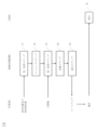
- FIG. 3 shows the operation of the route planning device of the present disclosure.
- the operation of the route planning device of the present disclosure includes a first acquisition step 21, a mapping step 22, a second acquisition step 23, a planning step 24, and a display step 25. This will be explained below with reference to FIGS. 2 and 3.
- the worker inputs the location of the utility pole in the work area, and the location of obstacles such as existing obstacles and utility pole equipment.
- the first acquisition unit 11 of the route planning device 10 acquires the input pillar positions and obstacle positions.
- the route planning device 10 may acquire the obstacle position from a sensor unit (not shown) external to the route planning device 10 that scans the work place.
- the route planning device 10 may also include a sensor section (not shown) that scans the work place, and the sensor section may scan the position of an obstacle.
- the first acquisition unit 11 acquires the obstacle position from the sensor unit. If the sensor section scans the obstacle position, the obstacle position can be acquired without human intervention.
- the first acquisition unit may further acquire the size of the heavy equipment and the size of the utility pole to be laid down. When searching for a route, it is possible to accurately calculate the locations through which heavy equipment can pass.
- mapping step The mapping unit 12 of the route planning device 10 applies the acquired pillar positions and obstacle positions to a map of the vicinity of the work site.
- Figure 4 shows a map showing the positions of pillars and obstacles.
- 31 is an obstacle position
- 32 is a pillar erection position.
- an existing utility pole is present at an obstacle position 31 marked with a black circle
- an existing electric wire is present at an obstacle position 31 indicated by a broken line.
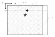
- FIG. 5 shows a map with work areas set.
- a work area 33 is set compared to FIG. 4.
- the center of the work area 33 is a predetermined distance away from the acquired pole erection position 32.
- the work area 33 is 30 m square
- the longitudinal direction of the existing electric wire is the X axis
- the center of the work area is 10 m from the pole erection position 32 in the Y axis direction.
- the worker inputs the number of divisions into which the work area is to be divided.
- the second acquisition unit 13 acquires the input division number.
- the planning unit 14 divides the work area into a matrix, as shown in FIG. 6, according to the number of divisions acquired by the second acquisition unit 13.
- the planning unit 14 specifies coordinates 34 where the heavy equipment is to be placed, as shown in FIG. It is preferable to use the tip of the heavy machinery as the coordinates of the heavy machinery.
- the planning unit 14 specifies the coordinates 35 at which the utility pole to be erected will lie, as shown in FIG.
- a route plan is generated from the coordinates 34 where the heavy equipment is placed to the position 32 where the utility pole is to be erected via the coordinates 35 where the utility pole is laid down.
- a route plan is generated by combining all the coordinates for placing heavy equipment and all the coordinates for laying down utility poles in the divided work area, and the search success probability and route travel time for each route plan are calculated. As shown in FIG. 9, the search success probability and route travel time are obtained for each coordinate where heavy machinery is placed and all coordinates where utility poles to be erected are laid down.
- RRT Rapidly Exploring Random Tree
- RRT* Rapidly Exploring Random Tree Star
- the search success probability is calculated by dividing the number of successful route searches by the number of route search attempts on the route from the coordinates where the heavy equipment is placed to the position where the utility pole is to be erected.
- the percentage of Examples of route search failures include failure to reach the position from the coordinates for placing heavy equipment to the coordinates for laying down the utility pole to be erected within the preset calculation time, or due to obstacles.
- the route may be closed.
- the number of searches is set in advance.
- Route travel time refers to the time required for heavy equipment to depart from the coordinates where the heavy equipment is placed, go through the coordinates where the utility pole to be erected is laid down, and reach the position where the pole is to be erected. is the relative speed divided by .
- the median value of the searched minutes may be used as the route travel time.
- the average value of the searched portion may be used as the route travel time.
- the first acquisition unit 11 acquires the size of heavy machinery and the size of utility poles, it is possible to search for a route with respect to obstacles taking these sizes into consideration.
- the size of heavy machinery include the overall length, width, and length of the arm that grips the utility pole.
- the size of a utility pole is determined by its length in the long axis direction. The route from the coordinates where the heavy equipment will be placed to the coordinates where the utility pole will be erected will take into account only the size of the heavy equipment, and the route from the coordinates where the utility pole will be laid down to the position where the pole will be erected will take into consideration the size of the heavy equipment and the size of the utility pole. good.
- the planning unit 14 aggregates the search success probability and route travel time in each generated route plan and converts it into a score.
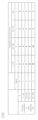
- FIG. 10 shows an example of aggregating and scoring.
- the search success probabilities (Success Probability of Pass Planning) are ranked in five stages from 0 to 4, and routes with high search success probabilities are ranked high and routes with low search success probabilities are ranked low.
- the route execution time is ranked in four stages from 1 to 4, and routes with short route travel times are ranked high and routes with long route travel times are ranked low.
- the product of the rank of search success probability and the rank of route travel time is calculated, and a score is given for each combination of the coordinates where heavy equipment is placed and the coordinates where utility poles are laid down.
- the display unit 15 displays a heat map of the scores aggregated for each coordinate (square mark) where the heavy equipment is placed.
- FIG. 12 An example of a heat map display is shown in FIG. In FIG. 12, the scores are 16, 12, and 9 in descending order of score. Only combinations that have good scores above a certain level may be heat mapped. For example, as shown in FIG. 12, the score is 9 or more.
- the route planning device of the present disclosure can also be realized by a computer and a program, and the program that causes the computer to function as the route planning device can be recorded on a recording medium or provided through a network.
- This disclosure can be applied to various industries including the information and communication industry.
Abstract
The present disclosure is a route planning device comprising: a first acquisition unit that acquires a pole erection position and obstacle positions; a mapping unit that maps the acquired pole erection position and obstacle positions on a map of the vicinity of a work site and sets a work area of a prescribed size centered around a position spaced a prescribed distance from the acquired pole erection position; a second acquisition unit that acquires a division number by which to divide the work area; a planning unit that, for each combination of coordinates at which heavy equipment is to be disposed and coordinates at which an electric pole to be erected is to be laid down in the work area divided by the division number acquired by the second acquisition unit, generates a route plan from the coordinates at which the heavy equipment is to be disposed to the pole erection position via the coordinates at which the electric pole to be erected is to be laid down, and aggregates and scores the search success probability and the route travel time for each route plan; and a display unit that displays a heat map of the aggregated score for each coordinate at which the heavy equipment is to be disposed.
Description
本開示は、電柱工事を行う重機の経路計画を生成する経路計画装置及び経路計画方法に関する。
The present disclosure relates to a route planning device and a route planning method that generate a route plan for heavy machinery that performs utility pole construction.
電柱工事は、操作者が重機を操作して行う。関連する作業手順を図1に示す。まず、作業者が現場調査を行い、障害物の位置と電柱を建てる位置(建柱位置)を把握し(51)、現場調査を基に、重機をどのように動作させればよいかの工事計画を作成していた(52)。作業者は、重機操作者に重機の操作を指示し(53)、操作者は作業者の指示に従って、重機を動作させていた(54)。
Utility pole construction is carried out by operators operating heavy machinery. The related work procedure is shown in Figure 1. First, workers conduct a site survey to understand the location of obstacles and the position where the utility pole will be erected (pole position) (51), and then, based on the site survey, determine how to operate the heavy equipment. I was making a plan (52). The worker instructed the heavy equipment operator to operate the heavy equipment (53), and the operator operated the heavy equipment according to the worker's instructions (54).
現場の作業環境によっては重機の配置する位置を変更したり、電柱を寝かせる位置を変更したりして、重機の経路計画を変更しなければならなかった。
Depending on the work environment at the site, we had to change the route plan for heavy equipment by changing the location of the heavy equipment or changing the position of the utility poles.
このような電柱工事では、重機を配置する位置や建柱する電柱を寝かせる位置の計画にはスキルが必要であり、その配置の策定にはスキルを持つ作業者の経験や感覚に頼る部分が多かった。
In this kind of utility pole work, skill is required to plan where to place heavy equipment and where to lay down the erected utility poles, and planning the placement often relies on the experience and intuition of skilled workers. Ta.
本開示は、作業者のスキルに頼ることなく、効率的な重機や電柱の配置を作業者に提示することができる経路計画装置及び経路計画方法を提供することを目的とする。
An object of the present disclosure is to provide a route planning device and a route planning method that can present efficient placement of heavy equipment and utility poles to workers without relying on the skills of the workers.
本開示の経路計画装置及び経路計画方法では、作業場所近辺のマップ上で重機を配置する座標と建柱する電柱を寝かせる座標の組み合わせを点数化し、重機を配置する座標ごとにヒートマップ表示することとした。
In the route planning device and route planning method of the present disclosure, a combination of coordinates for arranging heavy equipment and coordinates for laying down utility poles to be erected on a map near the work site is converted into points, and a heat map is displayed for each coordinate for arranging heavy equipment. And so.
具体的には、本開示は、
建柱位置及び障害物位置を取得する第一取得部と、
取得した前記建柱位置及び前記障害物位置を作業場所近辺のマップに当てはめ、取得した前記建柱位置から所定距離だけ離れた位置を中心に所定の広さの作業エリアを設定するマッピング部と、
前記作業エリアを分割する分割数を取得する第二取得部と、
前記第二取得部の取得する分割数に応じて分割した前記作業エリア内で重機を配置する全ての座標と建柱する電柱を寝かせる全ての座標との組み合わせで、重機を配置する座標から建柱する電柱を寝かせる座標を経由して建柱する位置までの経路計画を生成し、それぞれの経路計画における探索成功確率及び経路移動時間を集約して点数化する計画部と、
重機を配置する座標ごとに集約した点数をヒートマップ表示する表示部と、
を備える経路計画装置
である。 Specifically, this disclosure provides:
a first acquisition unit that acquires the position of the pillar and the position of the obstacle;
a mapping unit that applies the acquired pillar erected position and the obstacle position to a map in the vicinity of the work place, and sets a work area of a predetermined size centered on a position a predetermined distance from the acquired pillar erected position;
a second acquisition unit that acquires the number of divisions into which the work area is divided;
A combination of all the coordinates for arranging heavy equipment and all the coordinates for laying down utility poles to be erected in the work area divided according to the number of divisions acquired by the second acquisition unit, the construction of poles is determined from the coordinates for arranging heavy equipment. a planning unit that generates a route plan from the coordinates at which the utility pole is laid down to the position where the pole is erected, and aggregates the search success probability and route travel time in each route plan and converts it into points;
A display section that displays a heat map of the points aggregated for each coordinate where heavy equipment is placed;
This is a route planning device comprising:
本開示は、
前記計画部は、生成した経路計画で前記探索成功確率の高い経路を高くランク付けし、前記経路移動時間の短い経路を高くランク付けし、2つのランクに基づいて効率の良さで点数化する
ことを特徴とする。 This disclosure:
The planning unit ranks the route with a high probability of search success in the generated route plan, ranks the route with a short route travel time highly, and scores the route based on efficiency based on the two ranks. It is characterized by
本開示は、
前記第一取得部は、重機のサイズ及び電柱のサイズをさらに取得し、
前記計画部は、前記重機のサイズ及び前記電柱のサイズを考慮して経路計画を生成する
ことを特徴とする。 This disclosure:
The first acquisition unit further acquires the size of the heavy equipment and the size of the utility pole,
The planning unit is characterized in that it generates a route plan in consideration of the size of the heavy equipment and the size of the utility pole.
本開示は、
前記障害物位置をスキャンするセンサ部をさらに備え、
前記第一取得部は、前記センサ部から前記障害物位置を取得する
ことを特徴とする。 This disclosure:
further comprising a sensor unit that scans the obstacle position,
The first acquisition unit is characterized in that the first acquisition unit acquires the obstacle position from the sensor unit.
前記障害物位置をスキャンするセンサ部をさらに備え、
前記第一取得部は、前記センサ部から前記障害物位置を取得する
ことを特徴とする。 This disclosure:
further comprising a sensor unit that scans the obstacle position,
The first acquisition unit is characterized in that the first acquisition unit acquires the obstacle position from the sensor unit.
具体的には、本開示は、
経路計画装置が、
建柱位置及び障害物位置を取得する第一取得ステップと、
取得した前記建柱位置及び前記障害物位置を作業場所近辺のマップに当てはめ、取得した前記建柱位置から所定距離だけ離れた位置を中心に所定の広さの作業エリアを設定するマッピングステップと、
前記作業エリアを分割する分割数を取得する第二取得ステップと、
前記第二取得ステップで取得する分割数に応じて分割した前記作業エリア内で重機を配置する全ての座標と建柱する電柱を寝かせる全ての座標との組み合わせで、重機を配置する座標から建柱する電柱を寝かせる座標を経由して建柱する位置までの経路計画を生成し、それぞれの経路計画における探索成功確率及び経路移動時間を集約して点数化する計画ステップと、
重機を配置する座標ごとに集約した点数をヒートマップ表示する表示ステップと、
を実行する経路計画方法
である。 Specifically, this disclosure provides:
The route planning device
a first acquisition step of acquiring the position of the pillar and the position of the obstacle;
a mapping step of applying the acquired pillar erecting position and the obstacle position to a map of the vicinity of the work place, and setting a work area of a predetermined size centered on a position a predetermined distance from the acquired pillar erecting position;
a second acquisition step of acquiring the number of divisions into which the work area is divided;
A combination of all the coordinates for arranging heavy machinery and all the coordinates for laying down the utility poles to be erected in the work area divided according to the number of divisions obtained in the second acquisition step, from the coordinates for arranging the heavy equipment to the poles to be erected. a planning step of generating a route plan to the position where the pole is to be erected via the coordinates where the utility pole is to be erected, and summarizing the search success probability and route travel time in each route plan and converting it into points;
a display step of displaying a heat map of the points aggregated for each coordinate where the heavy equipment is placed;
This is a route planning method that executes
本開示は、
前記計画ステップでは、生成した経路計画で前記探索成功確率の高い経路を高くランク付けし、前記経路移動時間の短い経路を高くランク付けし、2つのランクに基づいて効率の良さで点数化する
ことを特徴とする。 This disclosure:
In the planning step, in the generated route plan, the route with a high search success probability is ranked highly, the route with a short route travel time is ranked highly, and points are scored based on the efficiency based on the two ranks. It is characterized by
本開示は、
前記第一取得ステップでは、重機のサイズ及び電柱のサイズをさらに取得し、
前記計画ステップでは、前記重機のサイズ及び前記電柱のサイズを考慮して経路計画を生成する
ことを特徴とする。 This disclosure:
In the first acquisition step, the size of the heavy equipment and the size of the utility pole are further acquired,
In the planning step, a route plan is generated taking into consideration the size of the heavy equipment and the size of the utility pole.
具体的には、本開示は、
コンピュータに請求項1に記載の経路計画装置として機能させるためのプログラム
である。 Specifically, this disclosure provides:
A program for causing a computer to function as the route planning device according toclaim 1.
コンピュータに請求項1に記載の経路計画装置として機能させるためのプログラム
である。 Specifically, this disclosure provides:
A program for causing a computer to function as the route planning device according to
なお、上記各開示の発明は、可能な限り組み合わせることができる。
Note that the inventions disclosed above can be combined as much as possible.
本開示によれば、作業者のスキルに頼ることなく、効率的な重機や電柱の配置を作業者に提示することができる経路計画装置及び経路計画方法を提供することができる。
According to the present disclosure, it is possible to provide a route planning device and a route planning method that can present efficient placement of heavy machinery and utility poles to a worker without relying on the worker's skills.
以下、本開示の実施形態について、図面を参照しながら詳細に説明する。なお、本開示は、以下に示す実施形態に限定されるものではない。これらの実施の例は例示に過ぎず、本開示は当業者の知識に基づいて種々の変更、改良を施した形態で実施することができる。なお、本明細書及び図面において符号が同じ構成要素は、相互に同一のものを示すものとする。
Hereinafter, embodiments of the present disclosure will be described in detail with reference to the drawings. Note that the present disclosure is not limited to the embodiments shown below. These implementation examples are merely illustrative, and the present disclosure can be implemented with various changes and improvements based on the knowledge of those skilled in the art. Note that components with the same reference numerals in this specification and the drawings indicate the same components.
本開示の経路計画装置の構成を図2に示す。図2において、経路計画装置10は、建柱位置及び障害物位置を取得する第一取得部11と、取得した建柱位置及び障害物位置を作業場所近辺のマップに当てはめ、取得した建柱位置から所定距離だけ離れた位置を中心に所定の広さの作業エリアを設定するマッピング部12と、作業エリアを分割する分割数を取得する第二取得部13と、第二取得部の取得する分割数に応じて分割した作業エリアに重機を配置する全ての座標と建柱する電柱を寝かせる全ての座標との組み合わせで、重機を配置する座標から建柱する電柱を寝かせる座標を経由して建柱する位置までの経路計画を生成し、それぞれの経路計画における探索成功確率及び経路移動時間を集約して点数化する計画部14と、重機を配置する座標ごとに集約した点数をヒートマップ表示する表示部15と、を備える。
The configuration of the route planning device of the present disclosure is shown in FIG. 2. In FIG. 2, the route planning device 10 includes a first acquisition unit 11 that acquires the pillar erected positions and obstacle positions, and a first acquisition unit 11 that acquires the pillar erected positions and obstacle positions, and applies the acquired pillar erected positions and obstacle positions to a map in the vicinity of the work place, and the acquired pillar erected positions. a mapping unit 12 that sets a work area of a predetermined size centered on a position a predetermined distance away from a location, a second acquisition unit 13 that acquires the number of divisions into which the work area is to be divided, and a division acquired by the second acquisition unit. By combining all the coordinates for placing heavy equipment in work areas divided according to the number of work areas and all the coordinates for laying down the utility poles to be erected, the poles are erected from the coordinates for placing the heavy equipment via the coordinates for laying down the utility poles to be erected. a planning unit 14 that generates a route plan to a location, aggregates the search success probability and route travel time in each route plan and converts it into a score, and a display that displays a heat map of the aggregated score for each coordinate where the heavy equipment is placed. 15.
本開示の経路計画装置の動作を図3に示す。図3において、本開示の経路計画装置の動作は、第一取得ステップ21と、マッピングステップ22と、第二取得ステップ23と、計画ステップ24と、表示ステップ25と、を備える。以下、図2及び図3を参照しながら説明する。
FIG. 3 shows the operation of the route planning device of the present disclosure. In FIG. 3, the operation of the route planning device of the present disclosure includes a first acquisition step 21, a mapping step 22, a second acquisition step 23, a planning step 24, and a display step 25. This will be explained below with reference to FIGS. 2 and 3.
(第一取得ステップ)
作業者は作業場所の中の電柱を建てる建柱位置、既設の障害物や電柱設備等の障害物位置を入力する。経路計画装置10の第一取得部11は、入力された建柱位置及び障害物位置を取得する。経路計画装置10は、経路計画装置10の外部に、作業場所をスキャンするセンサ部(不図示)から障害物位置を取得してもよい。また、経路計画装置10は、作業場所をスキャンするセンサ部(不図示)を備え、センサ部が障害物位置をスキャンしてもよい。第一取得部11は、センサ部から障害物位置を取得することになる。センサ部が障害物位置をスキャンすれば、人手を介さず障害物位置を取得することができる。 (First acquisition step)
The worker inputs the location of the utility pole in the work area, and the location of obstacles such as existing obstacles and utility pole equipment. Thefirst acquisition unit 11 of the route planning device 10 acquires the input pillar positions and obstacle positions. The route planning device 10 may acquire the obstacle position from a sensor unit (not shown) external to the route planning device 10 that scans the work place. The route planning device 10 may also include a sensor section (not shown) that scans the work place, and the sensor section may scan the position of an obstacle. The first acquisition unit 11 acquires the obstacle position from the sensor unit. If the sensor section scans the obstacle position, the obstacle position can be acquired without human intervention.
作業者は作業場所の中の電柱を建てる建柱位置、既設の障害物や電柱設備等の障害物位置を入力する。経路計画装置10の第一取得部11は、入力された建柱位置及び障害物位置を取得する。経路計画装置10は、経路計画装置10の外部に、作業場所をスキャンするセンサ部(不図示)から障害物位置を取得してもよい。また、経路計画装置10は、作業場所をスキャンするセンサ部(不図示)を備え、センサ部が障害物位置をスキャンしてもよい。第一取得部11は、センサ部から障害物位置を取得することになる。センサ部が障害物位置をスキャンすれば、人手を介さず障害物位置を取得することができる。 (First acquisition step)
The worker inputs the location of the utility pole in the work area, and the location of obstacles such as existing obstacles and utility pole equipment. The
第一取得部は、重機のサイズ及び寝かせる電柱のサイズをさらに取得してもよい。経路探索の際に、重機の通過できる箇所を正確に計算することができる。
The first acquisition unit may further acquire the size of the heavy equipment and the size of the utility pole to be laid down. When searching for a route, it is possible to accurately calculate the locations through which heavy equipment can pass.
(マッピングステップ)
経路計画装置10のマッピング部12は、取得した建柱位置及び障害物位置を作業場所近辺のマップに当てはめる。図4に建柱位置及び障害物位置を当てはめたマップを示す。図4において31は障害物位置、32は建柱位置である。図4では黒丸印の障害物位置31には既設の電柱、破線の障害物位置31には既設の電線が存在していることを表している。 (mapping step)
Themapping unit 12 of the route planning device 10 applies the acquired pillar positions and obstacle positions to a map of the vicinity of the work site. Figure 4 shows a map showing the positions of pillars and obstacles. In FIG. 4, 31 is an obstacle position, and 32 is a pillar erection position. In FIG. 4, an existing utility pole is present at an obstacle position 31 marked with a black circle, and an existing electric wire is present at an obstacle position 31 indicated by a broken line.
経路計画装置10のマッピング部12は、取得した建柱位置及び障害物位置を作業場所近辺のマップに当てはめる。図4に建柱位置及び障害物位置を当てはめたマップを示す。図4において31は障害物位置、32は建柱位置である。図4では黒丸印の障害物位置31には既設の電柱、破線の障害物位置31には既設の電線が存在していることを表している。 (mapping step)
The
次に、取得した建柱位置から所定距離だけ離れた位置を中心に所定の広さの作業エリアを設定する。図5に作業エリアを設定したマップを示す。図5では、図4に対して作業エリア33が設定されている。作業エリア33の中心は取得した建柱位置32から所定距離だけ離れた位置である。ここでは、作業エリア33を30m四方として、既設の電線の長手方向をX軸とし、建柱位置32からY軸方向に10mの位置を作業エリアの中心としている。これらの設定は例示である。
Next, a work area of a predetermined size is set centered on a position a predetermined distance away from the acquired pole erection position. Figure 5 shows a map with work areas set. In FIG. 5, a work area 33 is set compared to FIG. 4. The center of the work area 33 is a predetermined distance away from the acquired pole erection position 32. Here, the work area 33 is 30 m square, the longitudinal direction of the existing electric wire is the X axis, and the center of the work area is 10 m from the pole erection position 32 in the Y axis direction. These settings are illustrative.
(第二取得ステップ)
作業者は作業エリアを分割する分割する分割数を入力する。第二取得部13は、入力された分割数を取得する。 (Second acquisition step)
The worker inputs the number of divisions into which the work area is to be divided. Thesecond acquisition unit 13 acquires the input division number.
作業者は作業エリアを分割する分割する分割数を入力する。第二取得部13は、入力された分割数を取得する。 (Second acquisition step)
The worker inputs the number of divisions into which the work area is to be divided. The
(計画ステップ)
図6から図8を用いて計画ステップを説明する。図6から図8において、31は障害物位置、32は建柱位置、33は作業エリア、34は重機を配置する座標、35は電柱を寝かせる座標である。 (planning step)
The planning steps will be explained using FIGS. 6 to 8. 6 to 8, 31 is an obstacle position, 32 is a pole erected position, 33 is a work area, 34 is a coordinate for arranging heavy machinery, and 35 is a coordinate for laying down a utility pole.
計画部14は、第二取得部13の取得した分割数に従って、図6に示すように作業エリアをマトリクス状に分割する。計画部14は、図7に示すように重機を配置する座標34を指定する。重機の先端を重機の座標とすることが好ましい。次に、計画部14は、図8に示すように建柱する電柱を寝かせる座標35を指定する。
The planning unit 14 divides the work area into a matrix, as shown in FIG. 6, according to the number of divisions acquired by the second acquisition unit 13. The planning unit 14 specifies coordinates 34 where the heavy equipment is to be placed, as shown in FIG. It is preferable to use the tip of the heavy machinery as the coordinates of the heavy machinery. Next, the planning unit 14 specifies the coordinates 35 at which the utility pole to be erected will lie, as shown in FIG.
この状態で、重機を配置する座標34から建柱する電柱を寝かせる座標35を経由して建柱する位置32までの経路計画を生成する。分割した作業エリア内で重機を配置する全ての座標と建柱する電柱を寝かせる全ての座標との組み合わせで経路計画を生成し、それぞれの経路計画における探索成功確率及び経路移動時間を計算する。図9に示すように、重機を配置する座標ごとに、建柱する電柱を寝かせる全ての座標でそれぞれ探索成功確率と経路移動時間を得る。
In this state, a route plan is generated from the coordinates 34 where the heavy equipment is placed to the position 32 where the utility pole is to be erected via the coordinates 35 where the utility pole is laid down. A route plan is generated by combining all the coordinates for placing heavy equipment and all the coordinates for laying down utility poles in the divided work area, and the search success probability and route travel time for each route plan are calculated. As shown in FIG. 9, the search success probability and route travel time are obtained for each coordinate where heavy machinery is placed and all coordinates where utility poles to be erected are laid down.
経路探索手法としては、ランダムサンプリング手法を用いたパスプラニングがある。具体的には、RRT(Rapidly Exploring Random Tree)やRRT*(Rapidly Exploring Random Tree Star)が例示できる。探索成功確率とは、重機を配置する座標から建柱する電柱を寝かせる座標を経由して建柱する位置までの経路の中で、経路探索が成功した回数を、経路探索を試みた回数で除算した割合をいう。経路探索が失敗した例としては、予め設定した計算時間内に、重機を配置する座標から建柱する電柱を寝かせる座標を経由して建柱する位置にまで到達しなかった場合や障害物のために経路が閉ざされた場合がある。探索回数は予め設定しておく。経路移動時間は、重機が、重機を配置する座標を出発してから建柱する電柱を寝かせる座標を経由して建柱する位置にまで到達するまでの所要時間をいい、経路長を所定の速度で除算した相対的な速度である。探索した分の中央値を経路移動時間としてもよい。また、探索した分の平均値を経路移動時間としてもよい。
As a route search method, there is path planning using a random sampling method. Specifically, RRT (Rapidly Exploring Random Tree) and RRT* (Rapidly Exploring Random Tree Star) can be exemplified. The search success probability is calculated by dividing the number of successful route searches by the number of route search attempts on the route from the coordinates where the heavy equipment is placed to the position where the utility pole is to be erected. The percentage of Examples of route search failures include failure to reach the position from the coordinates for placing heavy equipment to the coordinates for laying down the utility pole to be erected within the preset calculation time, or due to obstacles. In some cases, the route may be closed. The number of searches is set in advance. Route travel time refers to the time required for heavy equipment to depart from the coordinates where the heavy equipment is placed, go through the coordinates where the utility pole to be erected is laid down, and reach the position where the pole is to be erected. is the relative speed divided by . The median value of the searched minutes may be used as the route travel time. Alternatively, the average value of the searched portion may be used as the route travel time.
第一取得部11が、重機のサイズ及び電柱のサイズを取得した場合は、障害物に対してこれらのサイズを考慮して経路探索することができる。重機のサイズとしては、全長、横幅、電柱を把持するアームの長さが例示できる。電柱のサイズとしては電柱の長軸方向の長さがある。重機を配置する座標から建柱する電柱を寝かせる座標までの経路は重機のサイズだけを考慮し、電柱を寝かせる座標から建柱する位置までの経路は重機のサイズ及び電柱のサイズを考慮してもよい。
When the first acquisition unit 11 acquires the size of heavy machinery and the size of utility poles, it is possible to search for a route with respect to obstacles taking these sizes into consideration. Examples of the size of heavy machinery include the overall length, width, and length of the arm that grips the utility pole. The size of a utility pole is determined by its length in the long axis direction. The route from the coordinates where the heavy equipment will be placed to the coordinates where the utility pole will be erected will take into account only the size of the heavy equipment, and the route from the coordinates where the utility pole will be laid down to the position where the pole will be erected will take into consideration the size of the heavy equipment and the size of the utility pole. good.
計画部14は、生成したそれぞれの経路計画における探索成功確率及び経路移動時間を集約して点数化する。集約して点数化する例を図10に示す。図10に示すように、探索成功確率(Success Probability of Pass Planning)を0から4までの5段階にランク付けし、探索成功確率の高い経路を高く、探索成功確率の低い経路を低くランク付けする。経路移動時間(Trajectory Execution Time)を1から4までの4段階にランク付けし、経路移動時間の短い経路を高く、経路移動時間の長い経路を低くランク付けする。探索成功確率のランクと経路移動時間のランクの積を計算し、重機を配置する座標と電柱を寝かせる座標の組み合わせごとの点数とする。
The planning unit 14 aggregates the search success probability and route travel time in each generated route plan and converts it into a score. FIG. 10 shows an example of aggregating and scoring. As shown in Figure 10, the search success probabilities (Success Probability of Pass Planning) are ranked in five stages from 0 to 4, and routes with high search success probabilities are ranked high and routes with low search success probabilities are ranked low. . The route execution time is ranked in four stages from 1 to 4, and routes with short route travel times are ranked high and routes with long route travel times are ranked low. The product of the rank of search success probability and the rank of route travel time is calculated, and a score is given for each combination of the coordinates where heavy equipment is placed and the coordinates where utility poles are laid down.
(表示ステップ)
例えば、重機を配置する座標ごとに、電柱を寝かせる座標に対する点数を視覚化すると、図11のようになる。一定以上の良好な点数の得られた組合せについてだけ視覚化してもよい。この場合は、探索可能エリアとして電柱を寝かせる座標(白丸印)が得られる。表示部15は、重機を配置する座標(四角印)ごとに集約した点数をヒートマップ表示する。ヒートマップ表示の例を図12に示す。図12では、良好な点数の順に16、12、9としている。一定以上の良好な点数の得られた組合せについてだけヒートマップ化してもよい。例えば、図12のように9以上の点数である。 (display step)
For example, if you visualize the points for each coordinate where a utility pole is laid down for each coordinate where heavy equipment is placed, the result will be as shown in Figure 11. Only combinations that have obtained good scores above a certain level may be visualized. In this case, the coordinates (white circles) where the utility pole is laid down can be obtained as a searchable area. Thedisplay unit 15 displays a heat map of the scores aggregated for each coordinate (square mark) where the heavy equipment is placed. An example of a heat map display is shown in FIG. In FIG. 12, the scores are 16, 12, and 9 in descending order of score. Only combinations that have good scores above a certain level may be heat mapped. For example, as shown in FIG. 12, the score is 9 or more.
例えば、重機を配置する座標ごとに、電柱を寝かせる座標に対する点数を視覚化すると、図11のようになる。一定以上の良好な点数の得られた組合せについてだけ視覚化してもよい。この場合は、探索可能エリアとして電柱を寝かせる座標(白丸印)が得られる。表示部15は、重機を配置する座標(四角印)ごとに集約した点数をヒートマップ表示する。ヒートマップ表示の例を図12に示す。図12では、良好な点数の順に16、12、9としている。一定以上の良好な点数の得られた組合せについてだけヒートマップ化してもよい。例えば、図12のように9以上の点数である。 (display step)
For example, if you visualize the points for each coordinate where a utility pole is laid down for each coordinate where heavy equipment is placed, the result will be as shown in Figure 11. Only combinations that have obtained good scores above a certain level may be visualized. In this case, the coordinates (white circles) where the utility pole is laid down can be obtained as a searchable area. The
作業者は重機を配置する座標ごとのヒートマップを入手すると、最適な重機を配置する座標と電柱を寝かせる座標の組み合わせを選択することができる。作業者は、この配置を基に重機を操作する。重機は作業者の操作に従って動作する(図3の26)。
Once a worker obtains a heat map for each coordinate where heavy machinery is to be placed, he or she can select the optimal combination of coordinates to place heavy machinery and coordinates to lay utility poles down. Workers operate heavy machinery based on this arrangement. The heavy machinery operates according to the operator's operations (26 in FIG. 3).
以上説明したように、本開示の経路計画装置及び経路計画方法によれば、作業者のスキルに頼ることなく、効率的な重機や電柱の配置を作業者に提示することができる。作業者は重機や電柱を配置する位置を事前に明確化することができ、建柱工事の時間短縮が可能になる。
As described above, according to the route planning device and route planning method of the present disclosure, efficient placement of heavy machinery and utility poles can be presented to the worker without relying on the skill of the worker. Workers can clarify in advance where heavy equipment and utility poles will be placed, reducing the time required for pole erection work.
本開示の経路計画装置はコンピュータとプログラムによっても実現でき、コンピュータに経路計画装置として機能させるプログラムを記録媒体に記録することも、ネットワークを通して提供することも可能である。
The route planning device of the present disclosure can also be realized by a computer and a program, and the program that causes the computer to function as the route planning device can be recorded on a recording medium or provided through a network.
本開示は情報通信産業を始め各種産業に適用することができる。
This disclosure can be applied to various industries including the information and communication industry.
10:経路計画装置
11:第一取得部
12:マッピング部
13:第二取得部
14:計画部
15:表示部
21:第一取得ステップ
22:マッピングステップ
23:第二取得ステップ
24:計画ステップ
25:表示ステップ
31:障害物位置
32: 建柱位置
33:作業エリア
34:重機を配置する座標
35:電柱を寝かせる座標 10: Route planning device 11: First acquisition unit 12: Mapping unit 13: Second acquisition unit 14: Planning unit 15: Display unit 21: First acquisition step 22: Mapping step 23: Second acquisition step 24: Planning step 25 : Display step 31: Obstacle position 32: Pole erection position 33: Work area 34: Coordinates for placing heavy machinery 35: Coordinates for laying utility pole
Claims (8)
- 建柱位置及び障害物位置を取得する第一取得部と、
取得した前記建柱位置及び前記障害物位置を作業場所近辺のマップに当てはめ、取得した前記建柱位置から所定距離だけ離れた位置を中心に所定の広さの作業エリアを設定するマッピング部と、
前記作業エリアを分割する分割数を取得する第二取得部と、
前記第二取得部の取得する分割数に応じて分割した前記作業エリア内で重機を配置する全ての座標と建柱する電柱を寝かせる全ての座標との組み合わせで、重機を配置する座標から建柱する電柱を寝かせる座標を経由して建柱する位置までの経路計画を生成し、それぞれの経路計画における探索成功確率及び経路移動時間を集約して点数化する計画部と、
重機を配置する座標ごとに集約した点数をヒートマップ表示する表示部と、
を備える経路計画装置。 a first acquisition unit that acquires the position of the pillar and the position of the obstacle;
a mapping unit that applies the acquired pillar erected position and the obstacle position to a map in the vicinity of the work place, and sets a work area of a predetermined size centered on a position a predetermined distance from the acquired pillar erected position;
a second acquisition unit that acquires the number of divisions into which the work area is divided;
A combination of all the coordinates for arranging heavy equipment and all the coordinates for laying down utility poles to be erected in the work area divided according to the number of divisions acquired by the second acquisition unit, the construction of poles is determined from the coordinates for arranging heavy equipment. a planning unit that generates a route plan from the coordinates at which the utility pole is laid down to the position where the pole is erected, and aggregates the search success probability and route travel time in each route plan and converts it into points;
A display section that displays a heat map of the points aggregated for each coordinate where heavy equipment is placed;
A route planning device comprising: - 前記計画部は、生成した経路計画で前記探索成功確率の高い経路を高くランク付けし、前記経路移動時間の短い経路を高くランク付けし、2つのランクに基づいて効率の良さで点数化することを特徴とする請求項1に記載の経路計画装置。 The planning unit ranks the route with a high probability of search success in the generated route plan, ranks the route with a short route travel time highly, and scores the route based on efficiency based on the two ranks. The route planning device according to claim 1, characterized in that:
- 前記第一取得部は、重機のサイズ及び電柱のサイズをさらに取得し、
前記計画部は、前記重機のサイズ及び前記電柱のサイズを考慮して経路計画を生成することを特徴とする請求項1に記載の経路計画装置。 The first acquisition unit further acquires the size of the heavy equipment and the size of the utility pole,
The route planning device according to claim 1, wherein the planning unit generates the route plan in consideration of the size of the heavy equipment and the size of the utility pole. - 前記障害物位置をスキャンするセンサ部をさらに備え、
前記第一取得部は、前記センサ部から前記障害物位置を取得することを特徴とする請求項1に記載の経路計画装置。 further comprising a sensor unit that scans the obstacle position,
The route planning device according to claim 1, wherein the first acquisition unit acquires the obstacle position from the sensor unit. - 経路計画装置が、
建柱位置及び障害物位置を取得する第一取得ステップと、
取得した前記建柱位置及び前記障害物位置を作業場所近辺のマップに当てはめ、取得した前記建柱位置から所定距離だけ離れた位置を中心に所定の広さの作業エリアを設定するマッピングステップと、
前記作業エリアを分割する分割数を取得する第二取得ステップと、
前記第二取得ステップで取得する分割数に応じて分割した前記作業エリア内で重機を配置する全ての座標と建柱する電柱を寝かせる全ての座標との組み合わせで、重機を配置する座標から建柱する電柱を寝かせる座標を経由して建柱する位置までの経路計画を生成し、それぞれの経路計画における探索成功確率及び経路移動時間を集約して点数化する計画ステップと、
重機を配置する座標ごとに集約した点数をヒートマップ表示する表示ステップと、
を実行する経路計画方法。 The route planning device
a first acquisition step of acquiring the position of the pillar and the position of the obstacle;
a mapping step of applying the obtained pillar erecting position and the obstacle position to a map in the vicinity of the work place, and setting a work area of a predetermined size centered on a position a predetermined distance away from the obtained pillar erecting position;
a second acquisition step of acquiring the number of divisions into which the work area is divided;
A combination of all the coordinates for arranging heavy equipment and all the coordinates for laying down utility poles to be erected in the work area divided according to the number of divisions obtained in the second acquisition step, the construction of poles is determined from the coordinates for arranging heavy equipment. a planning step of generating a route plan to the position where the utility pole is to be erected via the coordinates where the utility pole is to be erected, and aggregating the search success probability and route travel time in each route plan and converting it into a score;
a display step of displaying a heat map of the points aggregated for each coordinate where the heavy equipment is placed;
A route planning method that performs. - 前記計画ステップでは、生成した経路計画で前記探索成功確率の高い経路を高くランク付けし、前記経路移動時間の短い経路を高くランク付けし、2つのランクに基づいて効率の良さで点数化することを特徴とする請求項5に記載の経路計画方法。 In the planning step, in the generated route plan, the route with a high search success probability is ranked highly, the route with a short route travel time is ranked highly, and points are scored based on the efficiency based on the two ranks. The route planning method according to claim 5, characterized in that:
- 前記第一取得ステップでは、重機のサイズ及び電柱のサイズをさらに取得し、
前記計画ステップでは、前記重機のサイズ及び前記電柱のサイズを考慮して経路計画を生成することを特徴とする請求項5に記載の経路計画方法。
経路計画方法。 In the first acquisition step, the size of the heavy equipment and the size of the utility pole are further acquired,
6. The route planning method according to claim 5, wherein in the planning step, the route plan is generated in consideration of the size of the heavy equipment and the size of the utility pole.
Route planning method. - コンピュータに請求項1に記載の経路計画装置として機能させるためのプログラム。 A program for causing a computer to function as the route planning device according to claim 1.
Priority Applications (2)
| Application Number | Priority Date | Filing Date | Title |
|---|---|---|---|
| PCT/JP2022/026868 WO2024009439A1 (en) | 2022-07-06 | 2022-07-06 | Route planning device and route planning method |
| PCT/JP2023/001347 WO2024009537A1 (en) | 2022-07-06 | 2023-01-18 | Path planning device and path planning method |
Applications Claiming Priority (1)
| Application Number | Priority Date | Filing Date | Title |
|---|---|---|---|
| PCT/JP2022/026868 WO2024009439A1 (en) | 2022-07-06 | 2022-07-06 | Route planning device and route planning method |
Publications (1)
| Publication Number | Publication Date |
|---|---|
| WO2024009439A1 true WO2024009439A1 (en) | 2024-01-11 |
Family
ID=89453058
Family Applications (2)
| Application Number | Title | Priority Date | Filing Date |
|---|---|---|---|
| PCT/JP2022/026868 WO2024009439A1 (en) | 2022-07-06 | 2022-07-06 | Route planning device and route planning method |
| PCT/JP2023/001347 WO2024009537A1 (en) | 2022-07-06 | 2023-01-18 | Path planning device and path planning method |
Family Applications After (1)
| Application Number | Title | Priority Date | Filing Date |
|---|---|---|---|
| PCT/JP2023/001347 WO2024009537A1 (en) | 2022-07-06 | 2023-01-18 | Path planning device and path planning method |
Country Status (1)
| Country | Link |
|---|---|
| WO (2) | WO2024009439A1 (en) |
Citations (4)
| Publication number | Priority date | Publication date | Assignee | Title |
|---|---|---|---|---|
| JP2008217066A (en) * | 2007-02-28 | 2008-09-18 | Lexer Research Inc | Work planning support system |
| JP2010146456A (en) * | 2008-12-22 | 2010-07-01 | Chugoku Electric Power Co Inc:The | System and method for comprehensively managing progress of move of support to be moved |
| JP2016132538A (en) * | 2015-01-20 | 2016-07-25 | 株式会社日立製作所 | Carrying-in and installation work plan support device and carrying-in and installation work plan support method |
| WO2021049112A1 (en) * | 2019-09-11 | 2021-03-18 | コベルコ建機株式会社 | Simulator |
Family Cites Families (5)
| Publication number | Priority date | Publication date | Assignee | Title |
|---|---|---|---|---|
| JPH0724386Y2 (en) * | 1989-12-20 | 1995-06-05 | 株式会社アイチコーポレーション | Work vehicle stop position optimization device |
| JPH03271871A (en) * | 1990-03-20 | 1991-12-03 | Fujitsu Ltd | Segment data processing system |
| JPH0921231A (en) * | 1995-07-04 | 1997-01-21 | Hitachi Plant Eng & Constr Co Ltd | Working time calculation method |
| JP7132821B2 (en) * | 2018-10-31 | 2022-09-07 | 株式会社アイチコーポレーション | Work vehicle safety device |
| JP7423389B2 (en) * | 2020-04-01 | 2024-01-29 | 東北電力株式会社 | Work support equipment |
-
2022
- 2022-07-06 WO PCT/JP2022/026868 patent/WO2024009439A1/en unknown
-
2023
- 2023-01-18 WO PCT/JP2023/001347 patent/WO2024009537A1/en unknown
Patent Citations (4)
| Publication number | Priority date | Publication date | Assignee | Title |
|---|---|---|---|---|
| JP2008217066A (en) * | 2007-02-28 | 2008-09-18 | Lexer Research Inc | Work planning support system |
| JP2010146456A (en) * | 2008-12-22 | 2010-07-01 | Chugoku Electric Power Co Inc:The | System and method for comprehensively managing progress of move of support to be moved |
| JP2016132538A (en) * | 2015-01-20 | 2016-07-25 | 株式会社日立製作所 | Carrying-in and installation work plan support device and carrying-in and installation work plan support method |
| WO2021049112A1 (en) * | 2019-09-11 | 2021-03-18 | コベルコ建機株式会社 | Simulator |
Also Published As
| Publication number | Publication date |
|---|---|
| WO2024009537A1 (en) | 2024-01-11 |
Similar Documents
| Publication | Publication Date | Title |
|---|---|---|
| CN201402324Y (en) | High-tension overhead power transmission line airborne three-dimensional laser radar detecting system | |
| KR20060002964A (en) | Window stack control method, window management program, and window management apparatus | |
| JP2003202232A (en) | Navigation device and map display device | |
| CN109341702A (en) | Route planning method, device, equipment and storage medium in operating area | |
| CN110132291A (en) | Grating map generation method, system, equipment and storage medium for harbour | |
| CN110163065A (en) | Processing Method of Point-clouds, point cloud data loading method and device and equipment | |
| JP2004163480A5 (en) | ||
| CN109269505A (en) | A kind of grid equipment inspection route Intelligent planning method | |
| WO2022121288A1 (en) | Nuclear power plant three-dimensional wayfinding navigation method and system | |
| CN113033508A (en) | Point cloud-based fine routing inspection waypoint rapid generation method | |
| WO2024009439A1 (en) | Route planning device and route planning method | |
| CN111894054A (en) | Foundation pit excavation state monitoring system and method based on laser range finder networking | |
| CN110942660A (en) | Auxiliary parking system of electric power operation insulating bucket arm vehicle and parking position searching method thereof | |
| JP2022013830A (en) | Road network data generation method, device and computer program for autonomous vehicle | |
| CN111930143A (en) | Unmanned aerial vehicle flight path generation method and device, unmanned aerial vehicle and storage medium | |
| AU2022275523A1 (en) | Information processing method and system | |
| CN112053418B (en) | Hydropower engineering monitoring data drawing system and method | |
| CN105279305A (en) | Observation station choosing method based on ground three-dimensional laser scanning technology | |
| WO2024009431A1 (en) | Path planning device and path planning method | |
| KR100581380B1 (en) | Method For Drawing A Figure Using A Surveying Value Transferred From A Great Many Surveying Instrument | |
| JP7042322B1 (en) | Decision support device, decision support program and decision support method | |
| JP4071614B2 (en) | Surveying equipment | |
| JP3353212B2 (en) | Leader automatic creation method and leader automatic creation system | |
| JPH0694460A (en) | Data display apparatus | |
| JPS61194571A (en) | Graphic recognition mode |
Legal Events
| Date | Code | Title | Description |
|---|---|---|---|
| 121 | Ep: the epo has been informed by wipo that ep was designated in this application |
Ref document number: 22950233 Country of ref document: EP Kind code of ref document: A1 |