WO2024004997A1 - 画像形成装置 - Google Patents
画像形成装置 Download PDFInfo
- Publication number
- WO2024004997A1 WO2024004997A1 PCT/JP2023/023749 JP2023023749W WO2024004997A1 WO 2024004997 A1 WO2024004997 A1 WO 2024004997A1 JP 2023023749 W JP2023023749 W JP 2023023749W WO 2024004997 A1 WO2024004997 A1 WO 2024004997A1
- Authority
- WO
- WIPO (PCT)
- Prior art keywords
- opening
- cover
- lever
- image forming
- closing lever
- Prior art date
- Legal status (The legal status is an assumption and is not a legal conclusion. Google has not performed a legal analysis and makes no representation as to the accuracy of the status listed.)
- Ceased
Links
Images


Classifications
-
- G—PHYSICS
- G03—PHOTOGRAPHY; CINEMATOGRAPHY; ANALOGOUS TECHNIQUES USING WAVES OTHER THAN OPTICAL WAVES; ELECTROGRAPHY; HOLOGRAPHY
- G03G—ELECTROGRAPHY; ELECTROPHOTOGRAPHY; MAGNETOGRAPHY
- G03G21/00—Arrangements not provided for by groups G03G13/00 - G03G19/00, e.g. cleaning, elimination of residual charge
- G03G21/16—Mechanical means for facilitating the maintenance of the apparatus, e.g. modular arrangements
- G03G21/1642—Mechanical means for facilitating the maintenance of the apparatus, e.g. modular arrangements for connecting the different parts of the apparatus
- G03G21/1647—Mechanical connection means
-
- G—PHYSICS
- G03—PHOTOGRAPHY; CINEMATOGRAPHY; ANALOGOUS TECHNIQUES USING WAVES OTHER THAN OPTICAL WAVES; ELECTROGRAPHY; HOLOGRAPHY
- G03G—ELECTROGRAPHY; ELECTROPHOTOGRAPHY; MAGNETOGRAPHY
- G03G21/00—Arrangements not provided for by groups G03G13/00 - G03G19/00, e.g. cleaning, elimination of residual charge
- G03G21/16—Mechanical means for facilitating the maintenance of the apparatus, e.g. modular arrangements
- G03G21/1604—Arrangement or disposition of the entire apparatus
- G03G21/1619—Frame structures
-
- G—PHYSICS
- G03—PHOTOGRAPHY; CINEMATOGRAPHY; ANALOGOUS TECHNIQUES USING WAVES OTHER THAN OPTICAL WAVES; ELECTROGRAPHY; HOLOGRAPHY
- G03G—ELECTROGRAPHY; ELECTROPHOTOGRAPHY; MAGNETOGRAPHY
- G03G21/00—Arrangements not provided for by groups G03G13/00 - G03G19/00, e.g. cleaning, elimination of residual charge
- G03G21/16—Mechanical means for facilitating the maintenance of the apparatus, e.g. modular arrangements
- G03G21/1604—Arrangement or disposition of the entire apparatus
- G03G21/1623—Means to access the interior of the apparatus
- G03G21/1633—Means to access the interior of the apparatus using doors or covers
-
- G—PHYSICS
- G03—PHOTOGRAPHY; CINEMATOGRAPHY; ANALOGOUS TECHNIQUES USING WAVES OTHER THAN OPTICAL WAVES; ELECTROGRAPHY; HOLOGRAPHY
- G03G—ELECTROGRAPHY; ELECTROPHOTOGRAPHY; MAGNETOGRAPHY
- G03G21/00—Arrangements not provided for by groups G03G13/00 - G03G19/00, e.g. cleaning, elimination of residual charge
- G03G21/16—Mechanical means for facilitating the maintenance of the apparatus, e.g. modular arrangements
- G03G21/18—Mechanical means for facilitating the maintenance of the apparatus, e.g. modular arrangements using a processing cartridge, whereby the process cartridge comprises at least two image processing means in a single unit
-
- G—PHYSICS
- G03—PHOTOGRAPHY; CINEMATOGRAPHY; ANALOGOUS TECHNIQUES USING WAVES OTHER THAN OPTICAL WAVES; ELECTROGRAPHY; HOLOGRAPHY
- G03G—ELECTROGRAPHY; ELECTROPHOTOGRAPHY; MAGNETOGRAPHY
- G03G2221/00—Processes not provided for by group G03G2215/00, e.g. cleaning or residual charge elimination
- G03G2221/16—Mechanical means for facilitating the maintenance of the apparatus, e.g. modular arrangements and complete machine concepts
- G03G2221/1651—Mechanical means for facilitating the maintenance of the apparatus, e.g. modular arrangements and complete machine concepts for connecting the different parts
- G03G2221/1654—Locks and means for positioning or alignment
-
- G—PHYSICS
- G03—PHOTOGRAPHY; CINEMATOGRAPHY; ANALOGOUS TECHNIQUES USING WAVES OTHER THAN OPTICAL WAVES; ELECTROGRAPHY; HOLOGRAPHY
- G03G—ELECTROGRAPHY; ELECTROPHOTOGRAPHY; MAGNETOGRAPHY
- G03G2221/00—Processes not provided for by group G03G2215/00, e.g. cleaning or residual charge elimination
- G03G2221/16—Mechanical means for facilitating the maintenance of the apparatus, e.g. modular arrangements and complete machine concepts
- G03G2221/1678—Frame structures
- G03G2221/169—Structural door designs
Definitions
- the present invention relates to an image forming apparatus including a removable image forming unit.
- the image forming unit is installed at a predetermined position within the housing, and is provided so as to be able to be pulled out from the housing for maintenance and the like.
- Patent Document 1 there is an inner position that supports the process cartridge (corresponding to the image forming unit) and is located inside the apparatus main body (corresponding to the housing), and an outer position that is located outside the apparatus main body.
- An image forming apparatus is disclosed that includes a support member that is movable between.
- an object of the present invention to provide an image forming apparatus that can reliably prevent misalignment of an image forming unit.
- An image forming apparatus includes a housing having an opening on a side surface, a cover that can open and close the opening, and a cover disposed within the housing and pulled out through the opening along a predetermined pulling direction. a notch hole formed in a side edge of the opening along the pull-out direction; A pin for positioning the image forming unit in the housing, and a regulating mechanism for regulating the movement of the pin within the notched hole, and the regulating mechanism is configured to move from a state in which the pin is in contact with the pin within the notched hole.
- a press lever that is rotatable in a direction away from the notch hole, an opening/closing lever that rotates as the cover closes, and an elastically deformed state between the pressing lever and the opening/closing lever.
- an elastic member that is arranged to apply a load to the pressing lever in a direction opposite to the separating direction, and when the cover is open, an elastic return force of the elastic member applies the first load to the pressing lever.
- the opening/closing lever rotates to further elastically deform the elastic member, and due to the elastic return force of the elastic member, a second load larger than the first load is applied. This applies a load to the pressing lever.
- FIG. 1 is a side view schematically showing the internal configuration of an image forming apparatus according to an embodiment of the present invention.
- 1 is a perspective view showing a housing and an image forming unit of an image forming apparatus according to an embodiment of the present invention.
- FIG. 2 is a perspective view showing a pin of an image forming unit and a cutout hole of a housing in an image forming apparatus according to an embodiment of the present invention.
- 1 is a perspective view showing a cover of an image forming apparatus according to an embodiment of the present invention.
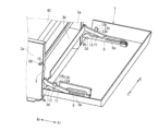
- FIG. 2 is a perspective view showing a regulating mechanism according to a first example in an image forming apparatus according to an embodiment of the present invention.
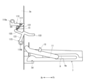
- FIG. 2 is a side view showing a regulating device according to a first example in an image forming apparatus according to an embodiment of the present invention.
- FIG. 3 is a side view showing the regulating mechanism according to the first example when the front cover is opened in the image forming apparatus according to the embodiment of the present invention.
- FIG. 3 is a side view showing the regulating mechanism according to the first embodiment in the middle of closing the front cover in the image forming apparatus according to the embodiment of the present invention.
- FIG. 3 is a side view showing the regulating mechanism according to the first embodiment in the middle of closing the front cover in the image forming apparatus according to the embodiment of the present invention.
- FIG. 3 is a side view showing the regulating mechanism according to the first embodiment in the middle of closing the front cover in the image forming apparatus according to the embodiment of the present invention.
- FIG. 3 is a side view showing the regulating mechanism according to the first example when the front cover is closed in the image forming apparatus according to the embodiment of the present invention.
- FIG. 7 is a side view showing an opening/closing lever according to a modification of the first embodiment.
- FIG. 3 is a partially enlarged side view of the stopper of the front cover.
- FIG. 7 is a side view showing a regulating mechanism when the front cover is closed in the image forming apparatus according to a modification of the first embodiment.
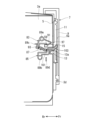
- FIG. 3 is a perspective view showing a regulating mechanism in an image forming apparatus according to a second embodiment of the present invention;
- FIG. FIG. 7 is a side view showing the regulating mechanism according to the second embodiment when the front cover is opened in the image forming apparatus according to the embodiment of the present invention.
- FIG. 7 is a side view showing a regulating mechanism according to a second embodiment in the middle of closing a front cover in an image forming apparatus according to an embodiment of the present invention.
- FIG. 7 is a side view showing the regulating mechanism according to the second embodiment when the front cover is closed in the image forming apparatus according to the embodiment of the present invention.
- FIG. 1 is a side view schematically showing the internal configuration of the image forming apparatus 1
- FIG. 2 is a perspective view showing the casing 3 and the image forming unit 43 of the image forming apparatus 1
- FIG. 4 is a perspective view showing the notch hole 15 of the housing 3
- FIG. 4 is a perspective view showing the front cover 7.
- Fr, Rr, L, and R shown in each figure indicate the front side, rear side, left side, and right side of the image forming apparatus 1, respectively.
- the casing 3 of the image forming apparatus 1 includes left and right side plates 3a facing each other in the left-right direction, a partition plate 3b connecting the left and right side plates 3a, and front and rear stays 3c.
- the partition plate 3b divides the space between the left and right side plates 3a into an upper space S1 and a lower space S2.
- the front and rear stays 3c are spaced apart from each other in the front-rear direction within the upper space S1.
- the opening 5 facing the front of the upper space S1 corresponds to the opening of the present invention.
- the opening 5 can be opened and closed by the front cover 7.
- the front cover 7 is an example of a cover in the present invention whose opening can be opened and closed.
- the front cover 7 has a width wider than the opening 5 and a height higher than the opening 5.
- the left and right side edges and the upper edge of the front cover 7 are curved inward.
- Left and right regulating members 9 are provided at the left and right ends of the inner surface of the front cover 7 along the height direction of the front cover 7.
- a long hole 9a extending in the longitudinal direction is formed in the left and right regulating members 9.
- a semicircular support portion 9b is formed at the lower end portions of the left and right regulating members 9.
- the front cover 7 is rotatably supported by the left and right side plates 3a.
- Cover rotation fulcrums 3d (see also FIG. 1) are provided on the left and right side plates 3a below the partition plate 3b.
- the left and right support portions 9b of the front cover 7 are rotatably supported by the cover rotation fulcrum 3d.
- the front cover 7 rotates between a closed position in which it stands upright from the cover rotation fulcrum 3d and closes the opening 5, and an open position in which it rotates on a horizontal plane from the cover rotation fulcrum 3d to open the opening 5.
- the front cover 7 is maintained in the open position by the stopper 11.
- One end of the stopper 11 is rotatably supported by the left and right side plates 3a above the cover rotation fulcrum 3d, and the other end of the stopper 11 is movably supported by the elongated hole 9a of the regulating member 9. .
- the other end of the stopper 11 is engaged with the end of the elongated hole 9a on the cover rotation fulcrum 3d side, thereby maintaining the front cover 7 in the open position.
- a protrusion piece 13 that protrudes into the space of the housing 3 along a direction orthogonal to the longitudinal direction is provided at the center of the side surface of the stopper 11 in the longitudinal direction.
- the protruding piece 13 has a rectangular parallelepiped shape with a predetermined thickness in the left-right direction, and has an upper surface 13a, a tip surface 13b, and an inclined surface 13c at the corner between the upper surface 13a and the tip surface 13b (see FIG. (See also 6).
- notch holes 15 of a predetermined length are formed in the left and right side edges of the opening 5 (left and right side plates 3a) along the horizontal direction. Furthermore, pins 17 protruding from the inner surfaces are provided at the rear portions of the left and right side plates 3a. The pin 17 is provided at the same height position as the notch hole 15.
- a regulating mechanism 81 (see FIG. 1, not shown in FIG. ) is provided on the left and right side edges of the opening 5 (the left and right side plates 3a).
- the regulating mechanism 81 will be described later.
- the regulating mechanism 81 is provided opposite the stopper 11 at each position where the stopper 11 is provided.
- a discharge tray 21 is provided on the top plate of the housing 3, and a sheet discharge port 23 is provided behind the discharge tray 21.
- the housing 3 includes a sheet feeding section 25, an electrophotographic image forming section 27, a fixing device 29, and a discharging device 31. Further, the housing 3 is provided with a sheet main conveyance path 33 and a reversal path 35 extending from the lower space S2 to the upper space S1.
- the sheet feeding section 25 includes a sheet feeding cassette 39 that is disposed in the lower space S2 and stores sheets, and a sheet feeding device 41 that feeds the sheets from the sheet feeding cassette 39 to the main conveyance path 33. There is.
- the paper feed cassette 39 is removable in the front-rear direction through the front opening of the lower space S2.
- the paper feed device 41 is arranged at the rear of the lower space S2.
- the image forming section 27 includes an image forming unit 43 arranged in the upper space S1, an intermediate transfer device 45, and an exposure device 47.
- the image forming unit 43 includes four individual units 51 corresponding to toner of four colors (yellow, magenta, cyan, and black), and left and right unit frames 53 that support the four individual units 51.
- the individual unit 51 includes a drum unit 55 including a photosensitive drum on which an electrostatic latent image is formed, and a developing unit 57 that develops the electrostatic latent image into a toner image using a one-component development method.
- the four individual units 51 are arranged side by side in the front-back direction and are removably supported by the left and right unit frames 53.
- a pin 59 and a notch hole 61 are formed in the left and right unit frames 53.
- the pins 59 are formed at the front end portions of the outer surfaces of the left and right unit frames 53 so as to protrude outward, respectively.
- the notch holes 61 are formed at the rear edges of the left and right unit frames 53 along the front-back direction.
- the cutout hole 61 is formed at the same height as the pin 59.
- the pin 59 is abutted against the back end (rear end) of the cutout hole 15 of the left and right side plates 3a (see FIG. It is positioned with respect to the housing 3 by being abutted against the pin 17 of 3a.
- the image forming unit 43 can be pulled out forward through the opening 5. In this way, the direction in which the image forming unit 43 is pulled out is the direction toward the front along the horizontal direction.
- the intermediate transfer device 45 includes an endless intermediate transfer belt 65, four primary transfer rollers 67 corresponding to the four individual units 51, and a secondary transfer roller 69.
- the intermediate transfer belt 65 is wound around a driving roller, a driven roller, and a tension roller that are arranged apart from each other in the front-rear direction.
- the four primary transfer rollers 67 are arranged in the hollow part of the intermediate transfer belt 65 in the front-rear direction.
- the secondary transfer roller 69 is arranged behind the intermediate transfer belt 65.
- a secondary transfer nip is formed between the intermediate transfer belt 65 and the secondary transfer roller 69.
- the intermediate transfer device 45 is arranged below the image forming unit 43 and fixed to the partition plate 3b. Specifically, the height of the left and right unit frames 53 of the image forming unit 43 is higher than the height of the individual units 51, and a predetermined space is formed between the unit frames 53 below the individual units 51. It has become. Intermediate transfer device 45 is arranged within this space. As shown in FIG. 1, the four primary transfer rollers 67 of the intermediate transfer device 45 face the photosensitive drums of the drum units 55 of the four individual units 51 of the image forming unit with the intermediate transfer belt 65 in between. A primary transfer nip is formed between the intermediate transfer belt 65 and the photosensitive drum.
- the exposure device 47 is supported by the front and rear stays 3c above the image forming unit 43.
- the fixing device 29 has a pressure roller and a heating roller, and forms a fixing nip between both rollers. As shown in FIG. 1, the fixing device 29 is arranged above the secondary transfer nip. The ejection device 31 is arranged above the fixing device 29 and inside the ejection port 23 .
- the main conveyance path 33 is formed from the paper feeding device 41 of the sheet feeding section 25 toward the ejection device 31 through the secondary transfer nip and the fixing nip.
- a pair of registration rollers 71 is arranged between the paper feed device 41 and the secondary transfer nip.
- the reversing path 35 branches from the main conveyance path 33 downstream of the fixing device 29 and merges with the main conveyance path upstream of the pair of registration rollers 71 .
- a toner image is formed on the individual unit 51 of the image forming unit 43 based on the image data exposed by the exposure device 47 .
- the toner image is transferred from the individual unit 51 to the intermediate transfer belt 65 in the primary transfer nip. As a result, a full-color toner image is formed on the intermediate transfer belt 65.
- sheets are conveyed from the sheet feeding cassette 39 to the main conveying path 33 by the sheet feeding device 41.
- the sheet is conveyed to the secondary transfer nip at appropriate timing by a pair of registration rollers 71.
- the toner image formed on the intermediate transfer belt 65 is transferred to one side of the sheet.
- the sheet is conveyed along the main conveyance path 33 to the fixing device 29, and the toner image is fixed to the sheet in a fixing nip.
- the sheet is further conveyed to the ejection device 31, and ejected by the ejection device 31 to the ejection tray 21 through the ejection port 23.
- the sheet with the toner image fixed on one side is conveyed from the main conveyance path 33 to the reversal path 35, and the toner image is transferred to the other side of the sheet in the secondary transfer nip. Thereafter, the toner image is fixed on the other side of the sheet by the fixing device 29, and then conveyed to the discharge device 31, which discharges the sheet through the discharge port 23 onto the discharge tray 21.
- FIG. 5 is a perspective view showing the regulating mechanism 81
- FIG. 6 is a side view showing the regulating mechanism 81 attached to the side plate 3a.
- FIG. 5 shows a regulating mechanism 81 attached to the left side plate 3a.
- the regulation mechanism 81 includes a pressing lever 83, an opening/closing lever 85, a compression coil spring 87 as an elastic member, and a support plate 89 that supports these.
- the bottom plate of the support plate 89 is provided with upper and lower rotation shafts 89a and 89b. Further, on the rear side plate of the support plate 89, an upper regulating piece 89c that projects inward is provided between both rotation shafts 89a and 89b. Further, the lower plate of the support plate 89 is provided with a lower regulating piece 89d that projects upward. Further, the support plate 89 is provided with a plurality of positioning pins 89e and hooks 89f.
- positioning holes and engagement pieces (not shown) corresponding to the positioning pins 89e and hooks 89f are provided on the outer surfaces of the left and right side plates 3a.
- the pressing lever 83 is a substantially L-shaped member when viewed from the left and right direction, and has a pressing arm 91 and a regulating arm 93 that are perpendicular to each other at approximately 90 degrees, and a bearing hole 95 between the arms 91 and 93. .
- a protrusion 97 having a triangular shape when viewed from the left and right is formed on the inner surface of the tip of the pressing arm 91 (the surface on the regulating arm 93 side).
- a diagonally downward spring support surface 93a is formed at the tip of the regulating arm 93.
- the press lever 83 is rotatably supported by a rotation shaft 89a on the upper side of the support plate 89, with the press arm 91 in the front and the restriction arm 93 in the rear.
- the regulating arm 93 comes into contact with the upper regulating piece 89c of the support plate 89 from below, and its upward rotation is restricted. As a result, the pressing arm 91 is maintained in a position with the protruding portion 97 facing directly downward, and while downward rotation is restricted, upward rotation is permitted.
- the opening/closing lever 85 is a zigzag-shaped member when viewed from the left and right directions in FIG. It has a contact portion 103 that is approximately L-shaped when viewed. A bearing hole 105 is formed at the base end of the regulating portion 101, and a diagonally upward spring support surface 101a is formed at the distal end. The contact portion 103 is formed to be bent at an obtuse angle when viewed from the left and right directions.
- the opening/closing lever 85 is rotatably supported by a rotation shaft 89b on the lower side of the support plate 89, with the contact portion 103 facing forward.
- the regulating portion 101 comes into contact with the lower regulating piece 89d of the support plate 89 from above, and its downward rotation is restricted. As a result, the opening/closing lever 85 is maintained in a position in which the contact portion 103 protrudes forward from the support plate 89.
- the compression coil spring 87 is a so-called push spring, and one end is fitted into a protrusion on the spring support surface 93a of the regulation arm 93 of the press lever 83, and the other end is fitted into the spring support of the regulation part 101 of the opening/closing lever 85. It is fitted into a protrusion on the surface 101a.
- the upward rotation of the regulating arm 93 of the press lever 83 is regulated, and the downward rotation of the regulating part 101 of the opening/closing lever 85 is regulated, so that both spring support surfaces 93a and 101a are Fixed position.
- the compression coil spring 87 is slightly compressed between both spring support surfaces 93a and 101a.
- the elastic return force generated by the compression of the compression coil spring 87 is applied to the regulating arm 93 of the pressing lever 83, pressing the regulating arm 93 against the upper regulating piece 89c.
- an upward load is applied to the regulating arm 93, and a downward load is applied to the pressing arm 91.
- the load applied to the pressing arm 91 is defined as a first load.
- FIG. 6 and FIGS. 7 to 10 are side views showing the regulating mechanism 81.
- the pins 17 of the left and right side plates 3a are inserted into the notch holes 61 of the left and right unit frames 53 of the imaging unit 43, as described above.
- the pin 59 of the image forming unit 43 enters into the notch hole 15 of the left and right side plates 3a.
- the rear surface of the pin 59 that protrudes outward from the side plate 3a through the cutout hole 15 comes into contact with the protrusion 97 of the pressing arm 91.
- the first load is applied to the pressing arm 91 along the downward direction (the direction opposite to the direction in which it moves away from the notch hole 15).
- the front cover 7 is rotated upward to close the opening 5.
- the contact portion 103 of the opening/closing lever 85 comes into contact with the protruding piece 13 of the stopper 11 of the front cover 7 from below, as shown in FIG. Specifically, the tip end surface 13b of the protruding piece 13 comes into contact with the lower surface of the contact portion 103.
- the opening/closing lever 85 is pushed up by the protruding piece 13, leaves the lower regulating piece 89d, and begins to rotate upward.
- the lower surface of the contact portion 103 contacts the distal end surface 13b, the inclined surface 13c, and the upper surface 13a of the protruding piece 13 in this order, and as shown in FIG. 10, the opening 5 is completely closed by the front cover 7. Then, the contact portion 103 rides on the protruding piece 13.
- the compression coil spring 87 begins to be compressed between the spring support surfaces 93a and 101a. Then, the elastic return force generated by the compression of the compression coil spring 87 increases, and the load applied to the pressing arm 91 increases. This load is defined as the second load.
- the second load is larger than the first load by the elastic return force generated by the elastic deformation of the compression coil spring 87 due to the rotation of the opening/closing lever 85. Thereby, the upward rotation of the press arm 91 is more strongly restricted.
- the front cover 7, which has been rotated until the opening 5 is closed, is fixed by a locking mechanism (not shown).
- the compression coil spring 87 is supported by the opening/closing lever 85 and applies a pressing force to the pressing lever 83.
- the opening/closing lever 85 is provided within the housing 3 with a contact portion 103 that is a part of the opening/closing lever 85 projecting outward from the housing 3 .
- the front cover 7 is provided with a protrusion piece 13 that protrudes from the surface of the front cover 7 on the side of the casing 3. The protruding piece 13 is provided at a position where it comes into contact with the contact portion 103 of the opening/closing lever 85 before the front cover 7 moves from the open position to the closed position with respect to the housing 3 .
- the opening/closing lever 85 rotates due to the pressing of the abutting part 103 by the protruding piece 13, and the compression coil spring 87 is rotated. It is further elastically deformed, and the second load is applied to the pressing lever 83 by the elastic return force of the compression coil spring 87.
- an appropriate load is applied to the pressing lever 83 when the front cover 7 is in the closed state and in the open state. Therefore, even if an external force such as vibration or impact is applied to the housing 3, the rotation of the pressing lever 83 is restricted, and the pin 59 of the image forming unit 43 can be prevented from moving inadvertently. Specifically, when the front cover 7 is open, the image forming unit 43 can be smoothly pulled out and attached by applying a load that does not prevent the pin 59 from passing through the notch hole 15. However, even if the pin 59 moves minutely, it does not have any particular effect.
- the load applied to the pressing lever 83 is increased, so even if an external force is applied due to vibration of the housing 3 during image forming operation, the position of the image forming unit 43 will not shift. can be prevented and image defects can be prevented.
- FIG. 11 is a side view showing an opening/closing lever 85 according to a modification of the first embodiment.
- the opening/closing lever 85 according to the modified embodiment differs from the opening/closing lever 85 according to the first embodiment in that a protrusion 1031 is further provided. That is, the opening/closing lever 85 according to the modified embodiment has the same configuration as the opening/closing lever 85 according to the first embodiment, except that a protrusion 1031 is further provided.
- the protruding portion 1031 is provided at a portion of the abutting portion 103 of the opening/closing lever 85 that abuts the protruding piece 13 of the front cover 7 so as to protrude from that portion.
- the protrusion 1031 is provided to extend over the entire area (over the entire width) in the width direction of the abutting portion 103 of the opening/closing lever 85 (in the depth direction of the page in FIG. 11).
- FIG. 12 is a partially enlarged side view of the stopper 11 of the front cover 7.
- the protruding piece 13 of the front cover 7 has a portion that faces the contact portion 103 of the opening/closing lever 85 when the front cover 7 is in a closed position with respect to the housing 3.
- a locking portion 13d that protrudes is provided.
- the stopper 11 and the protruding piece 13 of the front cover 7 are the same as those in the first embodiment shown above, but the protruding part of the protruding piece 13 is formed between the inclined surface 13c and the upper surface 13a. However, in a modified form, it functions as a locking portion 13d.
- the locking portion 13d contacts the protruding portion 1031 from the outer direction of the housing 3 (Fr (front) direction in FIG. 9). However, in this state, the locking portion 13d and the protrusion 1031 are once locked.
- the load applied to the pressing lever 83 becomes large, suppressing the movement of the pin 59 to prevent the image forming unit 43 from shifting, and also prevents the casing from shifting. Since the locking portion 13d is locked to the protrusion 1031 from the inside of the body 3, rotation of the front cover 7 in the direction in which the front cover 7 is in the open position is suppressed, and the front cover 7 is closed. The posture is maintained more stably than in the first embodiment. In addition, since the regulating mechanism 81 is provided at each position where the stopper 11 is provided so as to face the stopper 11, the engagement between the locking portion 13d and the protrusion 1031 when the front cover 7 is in the closed position.
- the front cover 7 is fixed (locked) at both end portions of the casing 3 when the front cover 7 is closed to the casing 3 because the locking is performed near both end portions of the casing 3 when viewed from the front side of the casing 3. Thereby, it is possible to prevent the front cover 7 from closing on one side of the housing 3 at only one of its opposite ends. Furthermore, since the opening/closing lever 85 in the modified form can be configured by providing the protrusion 1031 on the opening/closing lever 85 in the first embodiment, stable locking of the front cover 7 to the housing 3 can be achieved without further increasing the number of parts. can.
- the front cover 7 when the front cover 7 is rotated from the closed position to the open position, the front cover moves in a direction away from the casing 3 (in a direction toward the outside of the casing 3) due to the rotation.
- the locking portion 13d that locks onto the projection 1031 from the inside of the casing 3 moves beyond the projection 1031, as shown in FIG. It moves toward the Fr side (front side), and the locking portion 13d moves further toward the outside of the housing 3 than the protruding portion 1031.
- the opening/closing lever 85 rotates upward in FIG. 13 against the pressing force of the compression coil spring 87 due to the pressing force exerted on the projection 1031 when the locking portion 13d tries to pass over the projection 1031.
- the housing 3 can be moved toward the outside of the housing 3 beyond the projection 1031 of the stop portion 13d. After this, the front cover 7 rotates to the open position in the same manner as the operation shown in the first embodiment.
- FIG. 14 is a perspective view showing the regulating mechanism 81
- FIGS. 15 to 17 are side views showing the regulating mechanism 81.
- the regulating mechanism 81 includes a pressing lever 113, an opening/closing lever 115, a tension coil spring 117 as an elastic member, and a support plate 119 that supports these. That is, in the second embodiment, the tension coil spring 117 is used in place of the compression coil spring 87 in the first embodiment.
- the tension coil spring 117 is used in place of the compression coil spring 87 in the first embodiment.
- the pressing lever 113 is a linear member, and a triangular protrusion 121 is formed at the tip thereof when viewed from the left and right directions. Furthermore, a spring support pin 123 is formed at the tip. Further, a bearing hole 125 is formed at the base end of the pressing lever 113.
- the press lever 113 is rotatably supported by a rotation shaft 119a on the upper side of the support plate 119, with the tip thereof facing forward and the protrusion 121 facing downward. The press lever 113 comes into contact with the upper regulating piece 119c of the support plate 119 from above and is restricted from rotating downward, but is allowed to rotate upward.
- the opening/closing lever 115 is a substantially T-shaped member when viewed from the left and right, and includes a support arm 131, and an abutment arm 133 and a restriction arm 135 that extend in opposite directions from the tip of the support arm 131. .
- a bearing hole 137 is formed at the base end of the support arm 131 .
- a spring support pin 139 is formed at the tip of the regulating arm 135 .
- the opening/closing lever 115 is rotatably supported by a rotation shaft 119b on the lower side of the support plate 119, with the contact arm 133 facing forward.
- the regulating arm 135 comes into contact with a lower regulating piece (not shown) of the support plate 119 from above, and its downward rotation is restricted. As a result, the opening/closing lever 115 is maintained in a position where the contact arm 133 protrudes forward from the support plate 119.
- One end of the tension coil spring 117 is fixed to the spring support pin 123 of the pressing lever 113, and the other end is fixed to the spring support pin 139 of the opening/closing lever 115.
- the downward rotation of the pressing lever 113 is restricted, and the upward rotation of the restriction arm 135 of the opening/closing lever 115 is restricted, so the positions of both spring support pins 123 and 139 are fixed.
- the tension coil spring 117 is slightly stretched between both spring support pins 123 and 139. As a result, an elastic return force generated by the tension of the tension coil spring 117 is applied to the pressing lever 113, pressing the pressing lever 113 against the upper regulating piece 119c. That is, a downward load (first load) is applied to the pressing lever 113.
- the front cover 7 is opened and the protrusion 121 of the pressing lever 113 protrudes from above into the cutout hole 15 of the left and right side plates 3a, and the opening/closing lever
- the abutment arm 133 of 115 projects forward from the opening 5.
- the front cover 7 is rotated upward to close the opening 5.
- the contact arm 133 of the opening/closing lever 115 hits the protruding piece 13 of the stopper 11 of the front cover 7 from below, as shown in FIG. Specifically, the tip end surface 13b (FIG. 6) of the protruding piece 13 comes into contact with the lower surface of the abutting arm 133.
- the opening/closing lever 115 is pushed upward by the protruding piece 13, leaves the lower regulating piece, and begins to rotate upward.
- the contact arm 133 rides on the protruding piece 13.
- the tension coil spring 117 is supported by the opening/closing lever 85 and applies a force to the pressing lever 83 to draw the pressing lever 83.
- the opening/closing lever 85 is provided within the housing 3 with a contact portion 103 that is a part of the opening/closing lever 85 projecting outward from the housing 3 .
- the front cover 7 is provided with a protrusion piece 13 that protrudes from the surface of the front cover 7 on the side of the casing 3. The protruding piece 13 is provided at a position where it comes into contact with the contact portion 103 of the opening/closing lever 85 before the front cover 7 moves from the open position to the closed position with respect to the housing 3 .
- the opening/closing lever 85 is rotated by the pressing of the abutting part 103 by the protruding piece 13.
- the tension coil spring 117 is elastically deformed in the stretching direction, and the second load is applied to the pressing lever 83 by the elastic return force of the tension coil spring 117.
- the tension coil spring 117 begins to be pulled between the spring support pins 123 and 139. Then, the elastic return force (load) generated by the tension of the tension coil spring 117 increases, and the load applied to the pressing lever 113 increases. This load is defined as the second load. The second load is greater than the first load. Thereby, the upward rotation of the press lever 113 is more strongly restricted.
- an appropriate load is applied to the pressing lever 83 when the front cover 7 is closed and opened, so that external forces such as vibrations and shocks are prevented. Even if the pressing lever 83 is applied to the housing 3, rotation of the pressing lever 83 is restricted, and careless movement of the pin 59 of the image forming unit 43 can be prevented.
Landscapes
- Physics & Mathematics (AREA)
- General Physics & Mathematics (AREA)
- Engineering & Computer Science (AREA)
- Computer Vision & Pattern Recognition (AREA)
- Electrophotography Configuration And Component (AREA)
Priority Applications (2)
| Application Number | Priority Date | Filing Date | Title |
|---|---|---|---|
| US18/879,243 US12560888B2 (en) | 2022-06-29 | 2023-06-27 | Image forming apparatus |
| JP2024530867A JP7761150B2 (ja) | 2022-06-29 | 2023-06-27 | 画像形成装置 |
Applications Claiming Priority (2)
| Application Number | Priority Date | Filing Date | Title |
|---|---|---|---|
| JP2022104944 | 2022-06-29 | ||
| JP2022-104944 | 2022-06-29 |
Publications (1)
| Publication Number | Publication Date |
|---|---|
| WO2024004997A1 true WO2024004997A1 (ja) | 2024-01-04 |
Family
ID=89382295
Family Applications (1)
| Application Number | Title | Priority Date | Filing Date |
|---|---|---|---|
| PCT/JP2023/023749 Ceased WO2024004997A1 (ja) | 2022-06-29 | 2023-06-27 | 画像形成装置 |
Country Status (3)
| Country | Link |
|---|---|
| US (1) | US12560888B2 (https=) |
| JP (1) | JP7761150B2 (https=) |
| WO (1) | WO2024004997A1 (https=) |
Citations (4)
| Publication number | Priority date | Publication date | Assignee | Title |
|---|---|---|---|---|
| JPH03239265A (ja) * | 1990-02-16 | 1991-10-24 | Tokyo Electric Co Ltd | 像担持体ユニット保持装置 |
| JP2005157113A (ja) * | 2003-11-27 | 2005-06-16 | Canon Inc | 画像形成装置 |
| JP2011053281A (ja) * | 2009-08-31 | 2011-03-17 | Fuji Xerox Co Ltd | 開閉機構および画像形成装置 |
| WO2018088672A1 (en) * | 2016-11-09 | 2018-05-17 | S-Printing Solution Co., Ltd. | Image forming apparatus |
Family Cites Families (6)
| Publication number | Priority date | Publication date | Assignee | Title |
|---|---|---|---|---|
| KR100485794B1 (ko) * | 2003-01-18 | 2005-04-28 | 삼성전자주식회사 | 화상 형성 장치의 용지 공급 장치 |
| JP4549426B2 (ja) | 2008-09-29 | 2010-09-22 | キヤノン株式会社 | 電子写真画像形成装置 |
| JP4689750B2 (ja) | 2008-09-29 | 2011-05-25 | キヤノン株式会社 | 電子写真画像形成装置 |
| US10241584B2 (en) * | 2016-09-28 | 2019-03-26 | Lenovo (Singapore) Pte. Ltd. | Gesture detection |
| JP7027068B2 (ja) * | 2017-08-30 | 2022-03-01 | キヤノン株式会社 | 画像形成装置 |
| JP7255175B2 (ja) * | 2018-12-26 | 2023-04-11 | ブラザー工業株式会社 | 画像形成装置 |
-
2023
- 2023-06-27 JP JP2024530867A patent/JP7761150B2/ja active Active
- 2023-06-27 US US18/879,243 patent/US12560888B2/en active Active
- 2023-06-27 WO PCT/JP2023/023749 patent/WO2024004997A1/ja not_active Ceased
Patent Citations (4)
| Publication number | Priority date | Publication date | Assignee | Title |
|---|---|---|---|---|
| JPH03239265A (ja) * | 1990-02-16 | 1991-10-24 | Tokyo Electric Co Ltd | 像担持体ユニット保持装置 |
| JP2005157113A (ja) * | 2003-11-27 | 2005-06-16 | Canon Inc | 画像形成装置 |
| JP2011053281A (ja) * | 2009-08-31 | 2011-03-17 | Fuji Xerox Co Ltd | 開閉機構および画像形成装置 |
| WO2018088672A1 (en) * | 2016-11-09 | 2018-05-17 | S-Printing Solution Co., Ltd. | Image forming apparatus |
Also Published As
| Publication number | Publication date |
|---|---|
| US20250390057A1 (en) | 2025-12-25 |
| JPWO2024004997A1 (https=) | 2024-01-04 |
| JP7761150B2 (ja) | 2025-10-28 |
| US12560888B2 (en) | 2026-02-24 |
Similar Documents
| Publication | Publication Date | Title |
|---|---|---|
| JP5202074B2 (ja) | シート搬送装置及びこれを備えた画像形成装置 | |
| US10016996B2 (en) | Image forming apparatus | |
| US10179713B2 (en) | Sheet feeding device, feeding tray, and image forming apparatus | |
| JP2011053333A (ja) | 開閉機構および画像形成装置 | |
| JP2015209284A (ja) | シート搬送装置、およびこれを備えた画像形成装置 | |
| JP2007137559A (ja) | 給紙装置 | |
| JP5842868B2 (ja) | 給紙カセット | |
| US7533881B2 (en) | Sheet feeding device and image forming device with linked rotatable guide members | |
| WO2024004997A1 (ja) | 画像形成装置 | |
| JP2005031377A (ja) | 画像形成装置 | |
| JP5031648B2 (ja) | 手差しトレイ及びこれを備えた画像形成装置 | |
| JP5968106B2 (ja) | シート搬送装置及び画像形成装置 | |
| JP6583571B2 (ja) | 画像形成装置 | |
| US10048643B2 (en) | Image forming apparatus including cover unit provided on apparatus main body in a turnable manner | |
| JP6743773B2 (ja) | 画像形成装置 | |
| US9760040B2 (en) | Image forming apparatus including intermediate transfer unit and fixing unit | |
| JP2007121858A (ja) | ロック装置及び画像形成装置 | |
| JP7806457B2 (ja) | ラッチ機構、ラッチ装置、画像形成装置 | |
| JP2025149851A (ja) | 画像形成装置 | |
| JP2025149852A (ja) | 画像形成装置 | |
| JP4740822B2 (ja) | 画像形成装置の手差しトレイ構造 | |
| JP2025149853A (ja) | 画像形成装置 | |
| JPH09208106A (ja) | 排紙トレイ | |
| JP2006234855A (ja) | 画像形成装置 | |
| JP2009057170A (ja) | シート給送装置、及びそのシート給送装置を備える画像形成装置 |
Legal Events
| Date | Code | Title | Description |
|---|---|---|---|
| 121 | Ep: the epo has been informed by wipo that ep was designated in this application |
Ref document number: 23831437 Country of ref document: EP Kind code of ref document: A1 |
|
| WWE | Wipo information: entry into national phase |
Ref document number: 2024530867 Country of ref document: JP |
|
| WWE | Wipo information: entry into national phase |
Ref document number: 18879243 Country of ref document: US |
|
| NENP | Non-entry into the national phase |
Ref country code: DE |
|
| 122 | Ep: pct application non-entry in european phase |
Ref document number: 23831437 Country of ref document: EP Kind code of ref document: A1 |
|
| WWG | Wipo information: grant in national office |
Ref document number: 18879243 Country of ref document: US |