WO2024004119A1 - センシングシステム、センシング機器、及びセンシング方法 - Google Patents
センシングシステム、センシング機器、及びセンシング方法 Download PDFInfo
- Publication number
- WO2024004119A1 WO2024004119A1 PCT/JP2022/026166 JP2022026166W WO2024004119A1 WO 2024004119 A1 WO2024004119 A1 WO 2024004119A1 JP 2022026166 W JP2022026166 W JP 2022026166W WO 2024004119 A1 WO2024004119 A1 WO 2024004119A1
- Authority
- WO
- WIPO (PCT)
- Prior art keywords
- predetermined area
- abnormality
- vibration information
- optical fiber
- vibration
- Prior art date
- Legal status (The legal status is an assumption and is not a legal conclusion. Google has not performed a legal analysis and makes no representation as to the accuracy of the status listed.)
- Ceased
Links
Images


Classifications
-
- G—PHYSICS
- G01—MEASURING; TESTING
- G01H—MEASUREMENT OF MECHANICAL VIBRATIONS OR ULTRASONIC, SONIC OR INFRASONIC WAVES
- G01H9/00—Measuring mechanical vibrations or ultrasonic, sonic or infrasonic waves by using radiation-sensitive means, e.g. optical means
Definitions
- the present disclosure relates to a sensing system, sensing equipment, and sensing method.
- optical fiber sensing which uses optical fibers as sensors, has been developed.
- optical fiber sensing it is possible to detect abnormalities occurring around an optical fiber by detecting vibrations and sounds around the optical fiber.
- Patent Document 1 As a technique for detecting an abnormality using optical fiber sensing, there is a technique disclosed in Patent Document 1.
- the technology disclosed in Patent Document 1 is a technology for detecting unauthorized construction. Specifically, the technology disclosed in Patent Document 1 specifies and stores vibration patterns that occur when construction is performed using a combination of construction machine types, and also identifies and stores the vibration patterns that occur when construction is performed using a combination of construction machine types. Other combinations are stored and the stored information is used to detect unauthorized construction.
- Patent Document 1 specifies vibration patterns that occur during construction, and the location where abnormalities can be detected is limited to the construction site, so it is difficult to detect abnormalities in any area other than the construction site. The problem is that it is not possible.
- an object of the present disclosure is to provide a sensing system, a sensing device, and a sensing method that can contribute to abnormality detection in any area.
- a sensing system includes: Optical fiber laid in a predetermined area, a communication unit that inputs pulsed light into the optical fiber and receives backscattered light with respect to the pulsed light from the optical fiber; a specifying unit that specifies the normal state of the predetermined region based on vibration information representing the vibration intensity or vibration frequency per unit time at each position on the optical fiber, which is included in the backscattered light. .
- a sensing device includes: a communication unit that inputs pulsed light into an optical fiber installed in a predetermined area and receives backscattered light in response to the pulsed light from the optical fiber; a specifying unit that specifies the normal state of the predetermined region based on vibration information representing the vibration intensity or vibration frequency per unit time at each position on the optical fiber, which is included in the backscattered light. .
- a sensing method includes: A sensing method using a sensing device, a communication step of inputting pulsed light into an optical fiber laid in a predetermined area and receiving backscattered light with respect to the pulsed light from the optical fiber; a first identifying step of identifying the normal state of the predetermined region based on vibration information representing the vibration intensity or vibration frequency per unit time at each position on the optical fiber, which is included in the backscattered light; including.
- FIG. 1 is a diagram showing a configuration example of a sensing system according to Embodiment 1.
- FIG. 3 is a diagram showing an example of normal vibration information according to the first embodiment.
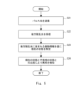
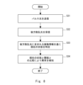
- FIG. 2 is a flow diagram illustrating an example of a schematic operation flow of the sensing system according to the first embodiment.
- FIG. 3 is a diagram illustrating a configuration example of a sensing system according to a second embodiment.
- FIG. 3 is a flow diagram illustrating an example of a schematic operation flow of the sensing system according to Embodiment 2.
- FIG. FIG. 7 is a diagram illustrating a configuration example of a sensing system according to a third embodiment. 7 is a diagram showing an example of the relationship between normal vibration information and threshold values according to Embodiment 3.
- FIG. 12 is a flow diagram illustrating an example of a schematic operation flow of the sensing system according to Embodiment 3.
- FIG. 7 is a diagram illustrating a configuration example of a sensing system according to a fourth embodiment.
- FIG. 12 is a flow diagram illustrating an example of a schematic operation flow of the sensing system according to Embodiment 4.
- FIG. It is a figure showing the example of composition of the sensing system concerning other embodiments.
- FIG. 3 is a block diagram illustrating an example of a hardware configuration of a computer that implements a sensing device according to another embodiment.
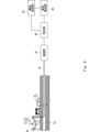
- the sensing system according to the first embodiment includes an optical fiber 10, a communication section 20, and a specific section 30. Note that in FIG. 1, it is assumed that the communication section 20 and the identification section 30 are provided separately.
- the identification unit 30 may be provided in a separate device from the communication unit 20, or may be provided on the cloud.
- the optical fiber 10 is laid in the area where it is desired to detect an abnormality.
- the optical fiber 10 may be placed in the air or buried underground, or a part of the optical fiber 10 may be placed in the air and the remaining part buried in the ground.
- a portion of the optical fiber 10 is suspended from a utility pole 91, and the remaining portion is passed through an underground conduit 92.
- the optical fiber 10 may be laid in the form of an optical fiber cable that is formed by covering the optical fiber 10. Further, one end of the optical fiber 10 is connected to the communication section 20.
- the communication unit 20 transmits pulsed light to the optical fiber 10. Then, as the pulsed light is transmitted through the optical fiber 10, backscattered light is generated. The communication unit 20 receives the backscattered light from the optical fiber 10.
- the identification unit 30 identifies the backscattered light based on the time difference between the time when the communication unit 20 transmits the pulsed light to the optical fiber 10 and the time when the communication unit 20 receives the backscattered light from the optical fiber 10. It is possible to calculate the position on the optical fiber 10 (the length of the optical fiber 10 from the communication unit 20) where this occurs.
- vibrations occur in the portions that are placed in the air due to, for example, being exposed to rain or wind.
- vibrations occur in the parts buried underground due to, for example, vehicles driving on the road directly above them.
- the characteristics (eg, wavelength) of the backscattered light transmitted through the optical fiber 10 change.
- the identification unit 30 can calculate the vibration intensity or vibration frequency at the position on the optical fiber 10 where the backscattered light is generated. Further, the specifying unit 30 calculates the vibration intensity or vibration frequency per unit time at each position on the optical fiber 10 based on the time course of the vibration intensity or vibration frequency at each position on the optical fiber 10. is possible.
- the identifying unit 30 can acquire vibration information representing the vibration intensity or vibration frequency per unit time at each position on the optical fiber 10.
- the vibration information is included in the backscattered light
- the identification unit 30 can acquire the vibration information included in the backscattered light by analyzing the characteristics of the backscattered light.
- the identification unit 30 determines whether the optical fiber 10 is installed by analyzing the backscattered light received by the communication unit 20 during normal times when no abnormality has occurred in the area where the optical fiber 10 is installed. Obtain normal vibration information of the area.
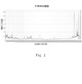
- FIG. 2 shows an example of normal vibration information acquired by the identification unit 30.
- FIG. 2 is an example in which the vibration information represents vibration intensity per unit time.
- the horizontal axis represents the position on the optical fiber 10 (the length of the optical fiber 10 from the communication section 20), and the vertical axis represents the vibration intensity per unit time.
- the vertical axis represents the vibration intensity per unit time (for example, about 30 seconds) averaged over several days (for example, about one week).
- the identifying unit 30 acquires vibration information as shown in FIG. 2, and then identifies the normal state of the area where the optical fiber 10 is installed based on the vibration information. That is, the identification unit 30 identifies the state represented by the vibration information as shown in FIG. 2 as the normal state.
- the communication unit 20 transmits pulsed light to the optical fiber 10 (step S11), and receives backscattered light in response to the pulsed light from the optical fiber 10 (step S12).
- the identification unit 30 analyzes the characteristics of the backscattered light to obtain vibration information representing the vibration intensity or vibration frequency per unit time at each position on the optical fiber 10, which is included in the backscattered light.
- the normal state of the area where the optical fiber 10 is installed is determined based on the acquired vibration information (step S13).
- the communication unit 20 transmits pulsed light to the optical fiber 10 and receives backscattered light with respect to the pulsed light from the optical fiber 10.
- the identification unit 30 identifies the area where the optical fiber 10 is installed based on vibration information representing the vibration intensity or vibration frequency per unit time at each position on the optical fiber 10, which is included in the backscattered light. Identify normal conditions.
- the sensing system according to the second embodiment differs from the configuration of the first embodiment shown in FIG. 1 described above in that an abnormality detection section 40 is added.
- the identification unit 30 identifies the normal state of the area where the optical fiber 10 is installed.
- the normal state identified by the identifying unit 30 is stored in a memory (not shown) or the like.
- the identifying unit 30 also identifies the current state of the area where the optical fiber 10 is installed based on the vibration information included in the backscattered light.
- the abnormality detection unit 40 compares the current state of the area where the optical fiber 10 is laid with the normal state, and based on the comparison result, the abnormality detection unit 40 , to detect whether an abnormality has occurred. For example, when the vibration information represents the vibration intensity per unit time, the abnormality detection unit 40 detects that the vibration intensity per unit time is a constant value than normal at any position on the optical fiber 10. If it becomes larger than that, it may be determined that an abnormality has occurred at that position.
- the communication unit 20 transmits pulsed light to the optical fiber 10 (step S21), and receives backscattered light with respect to the pulsed light from the optical fiber 10 (step S22).
- the identification unit 30 obtains vibration information representing the vibration intensity or vibration frequency per unit time at each position on the optical fiber 10, which is included in the backscattered light. is acquired, and the current state of the area where the optical fiber 10 is installed is specified based on the acquired vibration information (step S23).
- the abnormality detection unit 40 compares the current state of the area where the optical fiber 10 is installed with the normal state, and based on the comparison result, the abnormality detection unit 40 compares the current state of the area where the optical fiber 10 is installed with the normal state. , detect whether an abnormality has occurred (step S24).
- the identifying unit 30 identifies in advance the normal state of the area where the optical fiber 10 is installed based on the vibration information included in the backscattered light. I'll keep it. Then, the identifying unit 30 identifies the current state of the area where the optical fiber 10 is installed based on the vibration information included in the backscattered light.
- the abnormality detection unit 40 detects an abnormality in the area where the optical fiber 10 is installed by comparing the current state of the area where the optical fiber 10 is installed with the normal state. This makes it possible to detect abnormalities in any area where the optical fiber 10 is installed.
- the sensing system according to the third embodiment differs from the configuration of the second embodiment shown in FIG. 4 described above in that a threshold value setting section 50 is added.
- the identifying unit 30 identifies the normal state of the area where the optical fiber 10 is installed.
- the threshold setting unit 50 sets a threshold according to the normal state of the area where the optical fiber 10 is installed. For example, when the vibration information represents the vibration intensity per unit time, the threshold value is approximately 1.5 times the vibration intensity of the position in the normal vibration information for each position on the optical fiber 10. You can set it to a value.
- the threshold set by the threshold setting unit 50 is stored in a memory (not shown) or the like.
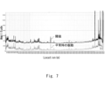
- FIG. 7 shows an example of the relationship between the normal vibration information acquired by the identification unit 30 and the threshold set by the threshold setting unit 50.
- the horizontal and vertical axes are the same as the horizontal and vertical axes in FIG.
- the identifying unit 30 also identifies the current state of the area where the optical fiber 10 is installed based on the vibration information included in the backscattered light.
- the abnormality detection unit 40 compares the current state of the area where the optical fiber 10 is installed with a threshold value, and based on the comparison result, determines whether an abnormality is currently occurring in the area where the optical fiber 10 is installed. detect whether For example, when the vibration information represents vibration intensity per unit time, the abnormality detection unit 40 detects that the vibration intensity per unit time has become larger than a threshold value at any position on the optical fiber 10. If so, it can be determined that an abnormality has occurred at that position.
- steps S31 to S33 which are similar to steps S21 to S23 in FIG. 5 of the second embodiment described above, are performed.
- the abnormality detection unit 40 compares the current state of the area where the optical fiber 10 is installed with the threshold value, and based on the comparison result, the abnormality is currently detected in the area where the optical fiber 10 is installed. It is detected whether this has occurred (step S34).
- the identification unit 30 identifies in advance the normal state of the area where the optical fiber 10 is installed based on the vibration information included in the backscattered light.
- the threshold value setting unit 50 presets a threshold value according to the specified normal state. Then, the identifying unit 30 identifies the current state of the area where the optical fiber 10 is installed based on the vibration information included in the backscattered light.
- the abnormality detection unit 40 detects an abnormality in the area where the optical fiber 10 is installed by comparing the current state of the area where the optical fiber 10 is installed with a threshold value. This makes it possible to detect abnormalities in any area where the optical fiber 10 is installed.
- the sensing system according to the fourth embodiment differs from the configuration of the third embodiment described above in FIG. 6 in that a notification section 60 is added.
- the notification unit 60 When the abnormality detection unit 40 determines that an abnormality has occurred in the area where the optical fiber 10 is installed, the notification unit 60 notifies a predetermined notification destination that an abnormality has occurred in that area. At this time, the notification unit 60 may notify the predetermined notification destination not only that an abnormality has occurred in the area where the optical fiber 10 is installed, but also the position where the abnormality has occurred.
- the predetermined notification destination may be, for example, a management center that manages the area where the optical fiber 10 is installed, a terminal installed in a local government, the country, or the like.
- the notification method may be, for example, a method of displaying a GUI (Graphical User Interface) screen on the display or monitor of the destination terminal, or a method of outputting a message audibly from the speaker of the destination terminal.
- step S44 if the abnormality detection unit 40 determines that an abnormality has occurred in the area where the optical fiber 10 is installed (Yes in step S44), the notification unit 60 sends a predetermined notification that an abnormality has occurred. It is notified first (step S45).
- the notification unit 60 notifies the area that an abnormality has occurred in the area where the optical fiber 10 is installed. Notify a predetermined notification destination of the occurrence. Thereby, the occurrence of an abnormality can be notified to a management center or the like that manages the area.
- the notification unit 60 may notify a predetermined notification destination not only that an abnormality has occurred in the area where the optical fiber 10 is installed, but also the position where the abnormality has occurred. This allows personnel at the management center and the like to quickly rush to the site where an abnormality has occurred. Other effects are similar to those of the third embodiment described above.
- FIG. 11 shows a configuration example of a sensing system in which a communication unit 20 and a identification unit 30 are provided inside a sensing device 70. Note that the sensing system shown in FIG. 11 has the abnormality detection section 40, the threshold value setting section 50, the notification section 60, etc. according to the second, third, and fourth embodiments described above added inside the sensing device 70. Also good.
- the vibration state may vary greatly over time.
- the amount of vehicle traffic on a road differs in the morning, noon, and evening, and may also vary depending on the day of the week. Therefore, the identifying unit 30 may identify the normal state for each day of the week or time, and the threshold setting unit 50 may set the threshold.
- the abnormality detection unit 40 may detect the abnormality by comparing the current state with a threshold value depending on the current day of the week or time.
- abnormal vibrations may periodically occur for a short period of time in the area where the optical fiber 10 is installed. For example, the warning sound of a train passing at a railroad crossing or a gate crossing does not last for more than one minute. Therefore, the identification unit 30, the abnormality detection unit 40, and the threshold value setting unit 50 may detect only vibrations that have continued for a predetermined period of time or more as targets for abnormality detection. That is, the identification unit 30 may remove vibrations that have not continued for a predetermined period of time or longer from the vibration information, and identify the normal state or the current state based on the vibration information after removal. In this case, the threshold value setting unit 50 may set the threshold value based on the normal state specified from the vibration information after removal. Further, the abnormality detection unit 40 may detect an abnormality by comparing the current state specified from the vibration information after removal and a threshold value set from the vibration information after removal.
- the identification unit 30, the abnormality detection unit 40, and the threshold value setting unit 50 learn the vibration patterns of abnormal vibrations that occur irregularly, and only detect vibrations other than the learned vibration patterns as targets for abnormality detection. good. That is, the identification unit 30 learns the vibration patterns of abnormal vibrations that occur irregularly, extracts only vibrations other than the learned vibration patterns from the vibration information, and determines whether normal vibrations occur based on the extracted vibration information.
- the state or current state may be specified.
- the threshold value setting unit 50 may set the threshold value based on the normal state specified from the extracted vibration information.
- the abnormality detection unit 40 may detect an abnormality by comparing the current state specified from the extracted vibration information and a threshold value set from the extracted vibration information.
- the computer 80 includes a processor 81, a memory 82, a storage 83, an input/output interface (input/output I/F) 84, a communication interface (communication I/F) 85, and the like.
- the processor 81, memory 82, storage 83, input/output interface 84, and communication interface 85 are connected by a data transmission path for mutually transmitting and receiving data.
- the processor 81 is an arithmetic processing device such as a CPU (Central Processing Unit) or a GPU (Graphics Processing Unit).
- the memory 82 is, for example, a RAM (Random Access Memory) or a ROM (Read Only Memory).
- the storage 83 is, for example, a storage device such as an HDD (Hard Disk Drive), an SSD (Solid State Drive), or a memory card. Further, the storage 83 may be a memory such as RAM or ROM.
- a program is stored in the storage 83.
- This program includes a set of instructions (or software code) that, when loaded into a computer, causes the computer 80 to perform one or more functions in the sensing device 70 described above.
- the components in the sensing device 70 described above may be realized by the processor 81 reading and executing a program stored in the storage 83.
- the storage function in the sensing device 70 described above may be realized by the memory 82 or the storage 83.
- the above-mentioned program may be stored in a non-transitory computer-readable medium or a tangible storage medium.
- computer-readable or tangible storage media may include RAM, ROM, flash memory, SSD or other memory technology, Compact Disc (CD)-ROM, Digital Versatile Disc (DVD), Blu-ray ( trademark) disk or other optical disk storage, magnetic cassette, magnetic tape, magnetic disk storage or other magnetic storage device.
- the program may be transmitted on a transitory computer-readable medium or a communication medium.
- transitory computer-readable or communication media includes electrical, optical, acoustic, or other forms of propagating signals.
- the input/output interface 84 is connected to a display device 841, an input device 842, a sound output device 843, and the like.
- the display device 841 is a device that displays a screen corresponding to the drawing data processed by the processor 81, such as an LCD (Liquid Crystal Display), a CRT (Cathode Ray Tube) display, or a monitor.
- the input device 842 is a device that receives operation input from an operator, and is, for example, a keyboard, a mouse, a touch sensor, or the like.
- the display device 841 and the input device 842 may be integrated and realized as a touch panel.
- the sound output device 843 is a device, such as a speaker, that outputs sound corresponding to the audio data processed by the processor 81.
- the communication interface 85 transmits and receives data to and from an external device.
- the communication interface 85 communicates with an external device via a wired communication path or a wireless communication path.
- Optical fiber laid in a predetermined area a communication unit that inputs pulsed light into the optical fiber and receives backscattered light with respect to the pulsed light from the optical fiber; a specifying unit that specifies the normal state of the predetermined region based on vibration information representing the vibration intensity or vibration frequency per unit time at each position on the optical fiber, which is included in the backscattered light. , sensing system.
- the identifying unit identifies the current state of the predetermined area based on the vibration information, The abnormality detection unit detects an abnormality in the predetermined area by comparing a current state of the predetermined area with a normal state.
- the sensing system described in Appendix 1. Additional note 3
- An anomaly detection section further comprising a threshold setting unit that sets a threshold according to a normal state of the predetermined area, The identifying unit identifies the current state of the predetermined area based on the vibration information, The abnormality detection unit detects an abnormality in the predetermined area by comparing the current state of the predetermined area with the threshold value.
- the identification unit identifies the normal state of the predetermined area for each day of the week or time,
- the threshold value setting unit sets the threshold value for each day of the week or time,
- the abnormality detection unit detects an abnormality in the predetermined area by comparing the current state of the predetermined area with the threshold value according to the current day of the week or time.
- the sensing system described in Appendix 3. (Appendix 5)
- the identification unit removes vibrations that have not continued for a predetermined period of time or more from the vibration information, and identifies a normal state and a current state of the predetermined area based on the vibration information after removal. Sensing system according to appendix 2 or 3.
- the identification unit learns a vibration pattern of abnormal vibrations that occur irregularly, extracts vibrations other than the learned vibration pattern from the vibration information, and identifies vibrations in the predetermined area based on the extracted vibration information. identify the normal state and current state of Sensing system according to appendix 2 or 3.
- (Appendix 7) further comprising a notification unit that notifies a predetermined notification destination that an abnormality has occurred in the predetermined area when the abnormality detection unit determines that an abnormality has occurred in the predetermined area; Sensing system according to appendix 2 or 3.
- (Appendix 8) a communication unit that inputs pulsed light into an optical fiber installed in a predetermined area and receives backscattered light in response to the pulsed light from the optical fiber; a specifying unit that specifies the normal state of the predetermined region based on vibration information representing the vibration intensity or vibration frequency per unit time at each position on the optical fiber, which is included in the backscattered light. , Sensing equipment. (Appendix 9) Additionally equipped with an anomaly detection section, The identifying unit identifies the current state of the predetermined area based on the vibration information, The abnormality detection unit detects an abnormality in the predetermined area by comparing a current state of the predetermined area with a normal state. Sensing equipment described in Appendix 8.
- An anomaly detection section further comprising a threshold setting unit that sets a threshold according to a normal state of the predetermined area,
- the identifying unit identifies the current state of the predetermined area based on the vibration information,
- the abnormality detection unit detects an abnormality in the predetermined area by comparing the current state of the predetermined area with the threshold value.
- Sensing equipment described in Appendix 8. (Appendix 11)
- the identification unit identifies the normal state of the predetermined area for each day of the week or time
- the threshold value setting unit sets the threshold value for each day of the week or time
- the abnormality detection unit detects an abnormality in the predetermined area by comparing the current state of the predetermined area with the threshold value according to the current day of the week or time.
- the sensing device described in Appendix 10. The identification unit removes vibrations that have not continued for a predetermined period of time or more from the vibration information, and identifies a normal state and a current state of the predetermined area based on the vibration information after removal.
- the sensing device according to appendix 9 or 10. The identification unit learns a vibration pattern of abnormal vibrations that occur irregularly, extracts vibrations other than the learned vibration pattern from the vibration information, and identifies vibrations in the predetermined area based on the extracted vibration information. identify the normal state and current state of The sensing device according to appendix 9 or 10.
- Appendix 14 further comprising a notification unit that notifies a predetermined notification destination that an abnormality has occurred in the predetermined area when the abnormality detection unit determines that an abnormality has occurred in the predetermined area;
- the sensing device according to appendix 9 or 10.
- Appendix 15 A sensing method using a sensing device, a communication step of inputting pulsed light into an optical fiber laid in a predetermined area and receiving backscattered light with respect to the pulsed light from the optical fiber; a first identifying step of identifying the normal state of the predetermined region based on vibration information representing the vibration intensity or vibration frequency per unit time at each position on the optical fiber, which is included in the backscattered light; including, Sensing method.
- (Appendix 16) a second identifying step of identifying the current state of the predetermined area based on the vibration information; further comprising an abnormality detection step of detecting an abnormality in the predetermined area by comparing the current state of the predetermined area with a normal state;
- the sensing method described in Appendix 15. (Appendix 17) a threshold setting step of setting a threshold according to the normal state of the predetermined area; a second identifying step of identifying the current state of the predetermined area based on the vibration information; further comprising: an abnormality detection step of detecting an abnormality in the predetermined area by comparing the current state of the predetermined area with the threshold value;
- the first identifying step the normal state of the predetermined area is identified for each day of the week or time
- the threshold value setting step the threshold value is set for each day of the week or each time
- an abnormality in the predetermined area is detected by comparing the current state of the predetermined area with the threshold value according to the current day of the week or time. The sensing method described in Appendix 17.
Landscapes
- Physics & Mathematics (AREA)
- General Physics & Mathematics (AREA)
- Measurement Of Mechanical Vibrations Or Ultrasonic Waves (AREA)
Priority Applications (2)
| Application Number | Priority Date | Filing Date | Title |
|---|---|---|---|
| PCT/JP2022/026166 WO2024004119A1 (ja) | 2022-06-30 | 2022-06-30 | センシングシステム、センシング機器、及びセンシング方法 |
| JP2024530191A JPWO2024004119A1 (https=) | 2022-06-30 | 2022-06-30 |
Applications Claiming Priority (1)
| Application Number | Priority Date | Filing Date | Title |
|---|---|---|---|
| PCT/JP2022/026166 WO2024004119A1 (ja) | 2022-06-30 | 2022-06-30 | センシングシステム、センシング機器、及びセンシング方法 |
Publications (1)
| Publication Number | Publication Date |
|---|---|
| WO2024004119A1 true WO2024004119A1 (ja) | 2024-01-04 |
Family
ID=89382257
Family Applications (1)
| Application Number | Title | Priority Date | Filing Date |
|---|---|---|---|
| PCT/JP2022/026166 Ceased WO2024004119A1 (ja) | 2022-06-30 | 2022-06-30 | センシングシステム、センシング機器、及びセンシング方法 |
Country Status (2)
| Country | Link |
|---|---|
| JP (1) | JPWO2024004119A1 (https=) |
| WO (1) | WO2024004119A1 (https=) |
Cited By (3)
| Publication number | Priority date | Publication date | Assignee | Title |
|---|---|---|---|---|
| WO2025169681A1 (ja) * | 2024-02-07 | 2025-08-14 | 日本電気株式会社 | 情報処理装置、情報処理方法、及びプログラム |
| WO2025249112A1 (ja) * | 2024-05-27 | 2025-12-04 | 日本電気株式会社 | 情報処理装置、方法、及び、プログラム |
| WO2026033600A1 (ja) * | 2024-08-05 | 2026-02-12 | Ntt株式会社 | 光ファイバケーブル点検箇所特定方法 |
Citations (5)
| Publication number | Priority date | Publication date | Assignee | Title |
|---|---|---|---|---|
| JPH06217421A (ja) * | 1993-01-13 | 1994-08-05 | Hitachi Ltd | 磁気浮上列車用軌道 |
| JP2007233643A (ja) * | 2006-02-28 | 2007-09-13 | Fujikura Ltd | 振動検知センサシステム及び振動検知方法 |
| JP2013170999A (ja) * | 2012-02-22 | 2013-09-02 | Hitachi Cable Ltd | 光ファイバ振動センサ |
| WO2020194494A1 (ja) * | 2019-03-26 | 2020-10-01 | 日本電気株式会社 | 構造物劣化検知システム及び構造物劣化検知方法 |
| WO2021117749A1 (ja) * | 2019-12-13 | 2021-06-17 | 日本電気株式会社 | 検出システム、検出装置及び検出方法 |
-
2022
- 2022-06-30 WO PCT/JP2022/026166 patent/WO2024004119A1/ja not_active Ceased
- 2022-06-30 JP JP2024530191A patent/JPWO2024004119A1/ja active Pending
Patent Citations (5)
| Publication number | Priority date | Publication date | Assignee | Title |
|---|---|---|---|---|
| JPH06217421A (ja) * | 1993-01-13 | 1994-08-05 | Hitachi Ltd | 磁気浮上列車用軌道 |
| JP2007233643A (ja) * | 2006-02-28 | 2007-09-13 | Fujikura Ltd | 振動検知センサシステム及び振動検知方法 |
| JP2013170999A (ja) * | 2012-02-22 | 2013-09-02 | Hitachi Cable Ltd | 光ファイバ振動センサ |
| WO2020194494A1 (ja) * | 2019-03-26 | 2020-10-01 | 日本電気株式会社 | 構造物劣化検知システム及び構造物劣化検知方法 |
| WO2021117749A1 (ja) * | 2019-12-13 | 2021-06-17 | 日本電気株式会社 | 検出システム、検出装置及び検出方法 |
Cited By (3)
| Publication number | Priority date | Publication date | Assignee | Title |
|---|---|---|---|---|
| WO2025169681A1 (ja) * | 2024-02-07 | 2025-08-14 | 日本電気株式会社 | 情報処理装置、情報処理方法、及びプログラム |
| WO2025249112A1 (ja) * | 2024-05-27 | 2025-12-04 | 日本電気株式会社 | 情報処理装置、方法、及び、プログラム |
| WO2026033600A1 (ja) * | 2024-08-05 | 2026-02-12 | Ntt株式会社 | 光ファイバケーブル点検箇所特定方法 |
Also Published As
| Publication number | Publication date |
|---|---|
| JPWO2024004119A1 (https=) | 2024-01-04 |
Similar Documents
| Publication | Publication Date | Title |
|---|---|---|
| WO2024004119A1 (ja) | センシングシステム、センシング機器、及びセンシング方法 | |
| JP2023184539A (ja) | 道路監視システム、道路監視装置、道路監視方法、及びプログラム | |
| JP7235115B2 (ja) | 光ファイバセンシングシステム、光ファイバセンシング機器、及び異常判断方法 | |
| JP2024014948A (ja) | 道路監視システム、道路監視装置、道路監視方法、及びプログラム | |
| WO2021010407A1 (ja) | 光ファイバセンシングシステム、光ファイバセンシング機器、及び配管劣化検知方法 | |
| US20230120899A1 (en) | Wind speed specification system, wind speed specification device, and wind speed specification method | |
| US20240377242A1 (en) | Optical fiber sensing system, optical fiber sensing apparatus, and breakage detection method | |
| JP7533566B2 (ja) | 監視システム、監視装置、及び監視方法 | |
| US12130174B2 (en) | Optical fiber sensing system and method for abnormal occurrence detection | |
| WO2021152787A1 (ja) | 構造物劣化検出システム、構造物劣化検出方法、及び構造物劣化検出装置 | |
| WO2021149192A1 (ja) | 電柱劣化検出システム、電柱劣化検出方法、及び電柱劣化検出装置 | |
| JP7718501B2 (ja) | 光ファイバセンシングシステム、光ファイバセンシング機器、及び光ファイバセンシング方法 | |
| US20240385032A1 (en) | Optical fiber sensing system, optical fiber sensing device, and road monitoring method | |
| US12416520B2 (en) | Specifying system, specifying apparatus, and specifying method | |
| US20240393163A1 (en) | Optical fiber sensing system, optical fiber sensing device, and road monitoring method | |
| US20240361178A1 (en) | Monitoring system, monitoring apparatus, and monitoring method | |
| US20260018049A1 (en) | Traffic monitoring device, traffic monitoring method, and non-transitory computer-readable medium | |
| US20230417593A1 (en) | Optical fiber sensing system, optical fiber sensing method, and optical fiber sensing device | |
| JP7574926B2 (ja) | 検出システム、検出装置、及び検出方法 | |
| JP7616402B2 (ja) | 検出システム、検出装置、及び検出方法 | |
| JP2025093826A (ja) | 車線変更検出システム、車線変更検出装置、車線変更検出方法、及びプログラム | |
| JP7831616B2 (ja) | 光ファイバセンシングシステム、光ファイバセンシング機器、及び破断検知方法 | |
| US20240133910A1 (en) | Evaluation apparatus, evaluation method, and non-transitory computer readable medium | |
| JP7505645B2 (ja) | 敷設状態特定システム、敷設状態特定装置、及び敷設状態特定方法 | |
| WO2024252476A1 (ja) | 振動監視システム、振動監視装置、及び振動監視方法 |
Legal Events
| Date | Code | Title | Description |
|---|---|---|---|
| 121 | Ep: the epo has been informed by wipo that ep was designated in this application |
Ref document number: 22949392 Country of ref document: EP Kind code of ref document: A1 |
|
| WWE | Wipo information: entry into national phase |
Ref document number: 2024530191 Country of ref document: JP |
|
| NENP | Non-entry into the national phase |
Ref country code: DE |
|
| 122 | Ep: pct application non-entry in european phase |
Ref document number: 22949392 Country of ref document: EP Kind code of ref document: A1 |