WO2024004119A1 - Sensing system, sensing device, and sensing method - Google Patents
Sensing system, sensing device, and sensing method Download PDFInfo
- Publication number
- WO2024004119A1 WO2024004119A1 PCT/JP2022/026166 JP2022026166W WO2024004119A1 WO 2024004119 A1 WO2024004119 A1 WO 2024004119A1 JP 2022026166 W JP2022026166 W JP 2022026166W WO 2024004119 A1 WO2024004119 A1 WO 2024004119A1
- Authority
- WO
- WIPO (PCT)
- Prior art keywords
- predetermined area
- abnormality
- vibration information
- optical fiber
- vibration
- Prior art date
Links
- 238000000034 method Methods 0.000 title claims description 29
- 239000013307 optical fiber Substances 0.000 claims abstract description 120
- 238000004891 communication Methods 0.000 claims abstract description 38
- 230000005856 abnormality Effects 0.000 claims description 115
- 238000001514 detection method Methods 0.000 claims description 59
- 230000002159 abnormal effect Effects 0.000 claims description 10
- 239000000284 extract Substances 0.000 claims description 5
- 230000004044 response Effects 0.000 claims description 4
- 238000010586 diagram Methods 0.000 description 11
- 238000010276 construction Methods 0.000 description 10
- 238000005516 engineering process Methods 0.000 description 6
- 230000006870 function Effects 0.000 description 2
- 230000003287 optical effect Effects 0.000 description 2
- 230000005540 biological transmission Effects 0.000 description 1
- 239000004973 liquid crystal related substance Substances 0.000 description 1
- 239000000203 mixture Substances 0.000 description 1
- 230000001151 other effect Effects 0.000 description 1
- 230000001902 propagating effect Effects 0.000 description 1
- 239000007787 solid Substances 0.000 description 1
Images


Classifications
-
- G—PHYSICS
- G01—MEASURING; TESTING
- G01H—MEASUREMENT OF MECHANICAL VIBRATIONS OR ULTRASONIC, SONIC OR INFRASONIC WAVES
- G01H9/00—Measuring mechanical vibrations or ultrasonic, sonic or infrasonic waves by using radiation-sensitive means, e.g. optical means
Definitions
- the present disclosure relates to a sensing system, sensing equipment, and sensing method.
- optical fiber sensing which uses optical fibers as sensors, has been developed.
- optical fiber sensing it is possible to detect abnormalities occurring around an optical fiber by detecting vibrations and sounds around the optical fiber.
- Patent Document 1 As a technique for detecting an abnormality using optical fiber sensing, there is a technique disclosed in Patent Document 1.
- the technology disclosed in Patent Document 1 is a technology for detecting unauthorized construction. Specifically, the technology disclosed in Patent Document 1 specifies and stores vibration patterns that occur when construction is performed using a combination of construction machine types, and also identifies and stores the vibration patterns that occur when construction is performed using a combination of construction machine types. Other combinations are stored and the stored information is used to detect unauthorized construction.
- Patent Document 1 specifies vibration patterns that occur during construction, and the location where abnormalities can be detected is limited to the construction site, so it is difficult to detect abnormalities in any area other than the construction site. The problem is that it is not possible.
- an object of the present disclosure is to provide a sensing system, a sensing device, and a sensing method that can contribute to abnormality detection in any area.
- a sensing system includes: Optical fiber laid in a predetermined area, a communication unit that inputs pulsed light into the optical fiber and receives backscattered light with respect to the pulsed light from the optical fiber; a specifying unit that specifies the normal state of the predetermined region based on vibration information representing the vibration intensity or vibration frequency per unit time at each position on the optical fiber, which is included in the backscattered light. .
- a sensing device includes: a communication unit that inputs pulsed light into an optical fiber installed in a predetermined area and receives backscattered light in response to the pulsed light from the optical fiber; a specifying unit that specifies the normal state of the predetermined region based on vibration information representing the vibration intensity or vibration frequency per unit time at each position on the optical fiber, which is included in the backscattered light. .
- a sensing method includes: A sensing method using a sensing device, a communication step of inputting pulsed light into an optical fiber laid in a predetermined area and receiving backscattered light with respect to the pulsed light from the optical fiber; a first identifying step of identifying the normal state of the predetermined region based on vibration information representing the vibration intensity or vibration frequency per unit time at each position on the optical fiber, which is included in the backscattered light; including.
- FIG. 1 is a diagram showing a configuration example of a sensing system according to Embodiment 1.
- FIG. 3 is a diagram showing an example of normal vibration information according to the first embodiment.
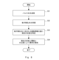
- FIG. 2 is a flow diagram illustrating an example of a schematic operation flow of the sensing system according to the first embodiment.
- FIG. 3 is a diagram illustrating a configuration example of a sensing system according to a second embodiment.
- FIG. 3 is a flow diagram illustrating an example of a schematic operation flow of the sensing system according to Embodiment 2.
- FIG. FIG. 7 is a diagram illustrating a configuration example of a sensing system according to a third embodiment. 7 is a diagram showing an example of the relationship between normal vibration information and threshold values according to Embodiment 3.
- FIG. 12 is a flow diagram illustrating an example of a schematic operation flow of the sensing system according to Embodiment 3.
- FIG. 7 is a diagram illustrating a configuration example of a sensing system according to a fourth embodiment.
- FIG. 12 is a flow diagram illustrating an example of a schematic operation flow of the sensing system according to Embodiment 4.
- FIG. It is a figure showing the example of composition of the sensing system concerning other embodiments.
- FIG. 3 is a block diagram illustrating an example of a hardware configuration of a computer that implements a sensing device according to another embodiment.
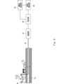
- the sensing system according to the first embodiment includes an optical fiber 10, a communication section 20, and a specific section 30. Note that in FIG. 1, it is assumed that the communication section 20 and the identification section 30 are provided separately.
- the identification unit 30 may be provided in a separate device from the communication unit 20, or may be provided on the cloud.
- the optical fiber 10 is laid in the area where it is desired to detect an abnormality.
- the optical fiber 10 may be placed in the air or buried underground, or a part of the optical fiber 10 may be placed in the air and the remaining part buried in the ground.
- a portion of the optical fiber 10 is suspended from a utility pole 91, and the remaining portion is passed through an underground conduit 92.
- the optical fiber 10 may be laid in the form of an optical fiber cable that is formed by covering the optical fiber 10. Further, one end of the optical fiber 10 is connected to the communication section 20.
- the communication unit 20 transmits pulsed light to the optical fiber 10. Then, as the pulsed light is transmitted through the optical fiber 10, backscattered light is generated. The communication unit 20 receives the backscattered light from the optical fiber 10.
- the identification unit 30 identifies the backscattered light based on the time difference between the time when the communication unit 20 transmits the pulsed light to the optical fiber 10 and the time when the communication unit 20 receives the backscattered light from the optical fiber 10. It is possible to calculate the position on the optical fiber 10 (the length of the optical fiber 10 from the communication unit 20) where this occurs.
- vibrations occur in the portions that are placed in the air due to, for example, being exposed to rain or wind.
- vibrations occur in the parts buried underground due to, for example, vehicles driving on the road directly above them.
- the characteristics (eg, wavelength) of the backscattered light transmitted through the optical fiber 10 change.
- the identification unit 30 can calculate the vibration intensity or vibration frequency at the position on the optical fiber 10 where the backscattered light is generated. Further, the specifying unit 30 calculates the vibration intensity or vibration frequency per unit time at each position on the optical fiber 10 based on the time course of the vibration intensity or vibration frequency at each position on the optical fiber 10. is possible.
- the identifying unit 30 can acquire vibration information representing the vibration intensity or vibration frequency per unit time at each position on the optical fiber 10.
- the vibration information is included in the backscattered light
- the identification unit 30 can acquire the vibration information included in the backscattered light by analyzing the characteristics of the backscattered light.
- the identification unit 30 determines whether the optical fiber 10 is installed by analyzing the backscattered light received by the communication unit 20 during normal times when no abnormality has occurred in the area where the optical fiber 10 is installed. Obtain normal vibration information of the area.
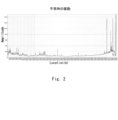
- FIG. 2 shows an example of normal vibration information acquired by the identification unit 30.
- FIG. 2 is an example in which the vibration information represents vibration intensity per unit time.
- the horizontal axis represents the position on the optical fiber 10 (the length of the optical fiber 10 from the communication section 20), and the vertical axis represents the vibration intensity per unit time.
- the vertical axis represents the vibration intensity per unit time (for example, about 30 seconds) averaged over several days (for example, about one week).
- the identifying unit 30 acquires vibration information as shown in FIG. 2, and then identifies the normal state of the area where the optical fiber 10 is installed based on the vibration information. That is, the identification unit 30 identifies the state represented by the vibration information as shown in FIG. 2 as the normal state.
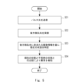
- the communication unit 20 transmits pulsed light to the optical fiber 10 (step S11), and receives backscattered light in response to the pulsed light from the optical fiber 10 (step S12).
- the identification unit 30 analyzes the characteristics of the backscattered light to obtain vibration information representing the vibration intensity or vibration frequency per unit time at each position on the optical fiber 10, which is included in the backscattered light.
- the normal state of the area where the optical fiber 10 is installed is determined based on the acquired vibration information (step S13).
- the communication unit 20 transmits pulsed light to the optical fiber 10 and receives backscattered light with respect to the pulsed light from the optical fiber 10.
- the identification unit 30 identifies the area where the optical fiber 10 is installed based on vibration information representing the vibration intensity or vibration frequency per unit time at each position on the optical fiber 10, which is included in the backscattered light. Identify normal conditions.
- the sensing system according to the second embodiment differs from the configuration of the first embodiment shown in FIG. 1 described above in that an abnormality detection section 40 is added.
- the identification unit 30 identifies the normal state of the area where the optical fiber 10 is installed.
- the normal state identified by the identifying unit 30 is stored in a memory (not shown) or the like.
- the identifying unit 30 also identifies the current state of the area where the optical fiber 10 is installed based on the vibration information included in the backscattered light.
- the abnormality detection unit 40 compares the current state of the area where the optical fiber 10 is laid with the normal state, and based on the comparison result, the abnormality detection unit 40 , to detect whether an abnormality has occurred. For example, when the vibration information represents the vibration intensity per unit time, the abnormality detection unit 40 detects that the vibration intensity per unit time is a constant value than normal at any position on the optical fiber 10. If it becomes larger than that, it may be determined that an abnormality has occurred at that position.
- the communication unit 20 transmits pulsed light to the optical fiber 10 (step S21), and receives backscattered light with respect to the pulsed light from the optical fiber 10 (step S22).
- the identification unit 30 obtains vibration information representing the vibration intensity or vibration frequency per unit time at each position on the optical fiber 10, which is included in the backscattered light. is acquired, and the current state of the area where the optical fiber 10 is installed is specified based on the acquired vibration information (step S23).
- the abnormality detection unit 40 compares the current state of the area where the optical fiber 10 is installed with the normal state, and based on the comparison result, the abnormality detection unit 40 compares the current state of the area where the optical fiber 10 is installed with the normal state. , detect whether an abnormality has occurred (step S24).
- the identifying unit 30 identifies in advance the normal state of the area where the optical fiber 10 is installed based on the vibration information included in the backscattered light. I'll keep it. Then, the identifying unit 30 identifies the current state of the area where the optical fiber 10 is installed based on the vibration information included in the backscattered light.
- the abnormality detection unit 40 detects an abnormality in the area where the optical fiber 10 is installed by comparing the current state of the area where the optical fiber 10 is installed with the normal state. This makes it possible to detect abnormalities in any area where the optical fiber 10 is installed.
- the sensing system according to the third embodiment differs from the configuration of the second embodiment shown in FIG. 4 described above in that a threshold value setting section 50 is added.
- the identifying unit 30 identifies the normal state of the area where the optical fiber 10 is installed.
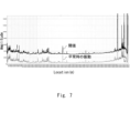
- the threshold setting unit 50 sets a threshold according to the normal state of the area where the optical fiber 10 is installed. For example, when the vibration information represents the vibration intensity per unit time, the threshold value is approximately 1.5 times the vibration intensity of the position in the normal vibration information for each position on the optical fiber 10. You can set it to a value.
- the threshold set by the threshold setting unit 50 is stored in a memory (not shown) or the like.
- FIG. 7 shows an example of the relationship between the normal vibration information acquired by the identification unit 30 and the threshold set by the threshold setting unit 50.
- the horizontal and vertical axes are the same as the horizontal and vertical axes in FIG.
- the identifying unit 30 also identifies the current state of the area where the optical fiber 10 is installed based on the vibration information included in the backscattered light.
- the abnormality detection unit 40 compares the current state of the area where the optical fiber 10 is installed with a threshold value, and based on the comparison result, determines whether an abnormality is currently occurring in the area where the optical fiber 10 is installed. detect whether For example, when the vibration information represents vibration intensity per unit time, the abnormality detection unit 40 detects that the vibration intensity per unit time has become larger than a threshold value at any position on the optical fiber 10. If so, it can be determined that an abnormality has occurred at that position.
- steps S31 to S33 which are similar to steps S21 to S23 in FIG. 5 of the second embodiment described above, are performed.
- the abnormality detection unit 40 compares the current state of the area where the optical fiber 10 is installed with the threshold value, and based on the comparison result, the abnormality is currently detected in the area where the optical fiber 10 is installed. It is detected whether this has occurred (step S34).
- the identification unit 30 identifies in advance the normal state of the area where the optical fiber 10 is installed based on the vibration information included in the backscattered light.
- the threshold value setting unit 50 presets a threshold value according to the specified normal state. Then, the identifying unit 30 identifies the current state of the area where the optical fiber 10 is installed based on the vibration information included in the backscattered light.
- the abnormality detection unit 40 detects an abnormality in the area where the optical fiber 10 is installed by comparing the current state of the area where the optical fiber 10 is installed with a threshold value. This makes it possible to detect abnormalities in any area where the optical fiber 10 is installed.
- the sensing system according to the fourth embodiment differs from the configuration of the third embodiment described above in FIG. 6 in that a notification section 60 is added.
- the notification unit 60 When the abnormality detection unit 40 determines that an abnormality has occurred in the area where the optical fiber 10 is installed, the notification unit 60 notifies a predetermined notification destination that an abnormality has occurred in that area. At this time, the notification unit 60 may notify the predetermined notification destination not only that an abnormality has occurred in the area where the optical fiber 10 is installed, but also the position where the abnormality has occurred.
- the predetermined notification destination may be, for example, a management center that manages the area where the optical fiber 10 is installed, a terminal installed in a local government, the country, or the like.
- the notification method may be, for example, a method of displaying a GUI (Graphical User Interface) screen on the display or monitor of the destination terminal, or a method of outputting a message audibly from the speaker of the destination terminal.
- step S44 if the abnormality detection unit 40 determines that an abnormality has occurred in the area where the optical fiber 10 is installed (Yes in step S44), the notification unit 60 sends a predetermined notification that an abnormality has occurred. It is notified first (step S45).
- the notification unit 60 notifies the area that an abnormality has occurred in the area where the optical fiber 10 is installed. Notify a predetermined notification destination of the occurrence. Thereby, the occurrence of an abnormality can be notified to a management center or the like that manages the area.
- the notification unit 60 may notify a predetermined notification destination not only that an abnormality has occurred in the area where the optical fiber 10 is installed, but also the position where the abnormality has occurred. This allows personnel at the management center and the like to quickly rush to the site where an abnormality has occurred. Other effects are similar to those of the third embodiment described above.
- FIG. 11 shows a configuration example of a sensing system in which a communication unit 20 and a identification unit 30 are provided inside a sensing device 70. Note that the sensing system shown in FIG. 11 has the abnormality detection section 40, the threshold value setting section 50, the notification section 60, etc. according to the second, third, and fourth embodiments described above added inside the sensing device 70. Also good.
- the vibration state may vary greatly over time.
- the amount of vehicle traffic on a road differs in the morning, noon, and evening, and may also vary depending on the day of the week. Therefore, the identifying unit 30 may identify the normal state for each day of the week or time, and the threshold setting unit 50 may set the threshold.
- the abnormality detection unit 40 may detect the abnormality by comparing the current state with a threshold value depending on the current day of the week or time.
- abnormal vibrations may periodically occur for a short period of time in the area where the optical fiber 10 is installed. For example, the warning sound of a train passing at a railroad crossing or a gate crossing does not last for more than one minute. Therefore, the identification unit 30, the abnormality detection unit 40, and the threshold value setting unit 50 may detect only vibrations that have continued for a predetermined period of time or more as targets for abnormality detection. That is, the identification unit 30 may remove vibrations that have not continued for a predetermined period of time or longer from the vibration information, and identify the normal state or the current state based on the vibration information after removal. In this case, the threshold value setting unit 50 may set the threshold value based on the normal state specified from the vibration information after removal. Further, the abnormality detection unit 40 may detect an abnormality by comparing the current state specified from the vibration information after removal and a threshold value set from the vibration information after removal.
- the identification unit 30, the abnormality detection unit 40, and the threshold value setting unit 50 learn the vibration patterns of abnormal vibrations that occur irregularly, and only detect vibrations other than the learned vibration patterns as targets for abnormality detection. good. That is, the identification unit 30 learns the vibration patterns of abnormal vibrations that occur irregularly, extracts only vibrations other than the learned vibration patterns from the vibration information, and determines whether normal vibrations occur based on the extracted vibration information.
- the state or current state may be specified.
- the threshold value setting unit 50 may set the threshold value based on the normal state specified from the extracted vibration information.
- the abnormality detection unit 40 may detect an abnormality by comparing the current state specified from the extracted vibration information and a threshold value set from the extracted vibration information.
- the computer 80 includes a processor 81, a memory 82, a storage 83, an input/output interface (input/output I/F) 84, a communication interface (communication I/F) 85, and the like.
- the processor 81, memory 82, storage 83, input/output interface 84, and communication interface 85 are connected by a data transmission path for mutually transmitting and receiving data.
- the processor 81 is an arithmetic processing device such as a CPU (Central Processing Unit) or a GPU (Graphics Processing Unit).
- the memory 82 is, for example, a RAM (Random Access Memory) or a ROM (Read Only Memory).
- the storage 83 is, for example, a storage device such as an HDD (Hard Disk Drive), an SSD (Solid State Drive), or a memory card. Further, the storage 83 may be a memory such as RAM or ROM.
- a program is stored in the storage 83.
- This program includes a set of instructions (or software code) that, when loaded into a computer, causes the computer 80 to perform one or more functions in the sensing device 70 described above.
- the components in the sensing device 70 described above may be realized by the processor 81 reading and executing a program stored in the storage 83.
- the storage function in the sensing device 70 described above may be realized by the memory 82 or the storage 83.
- the above-mentioned program may be stored in a non-transitory computer-readable medium or a tangible storage medium.
- computer-readable or tangible storage media may include RAM, ROM, flash memory, SSD or other memory technology, Compact Disc (CD)-ROM, Digital Versatile Disc (DVD), Blu-ray ( trademark) disk or other optical disk storage, magnetic cassette, magnetic tape, magnetic disk storage or other magnetic storage device.
- the program may be transmitted on a transitory computer-readable medium or a communication medium.
- transitory computer-readable or communication media includes electrical, optical, acoustic, or other forms of propagating signals.
- the input/output interface 84 is connected to a display device 841, an input device 842, a sound output device 843, and the like.
- the display device 841 is a device that displays a screen corresponding to the drawing data processed by the processor 81, such as an LCD (Liquid Crystal Display), a CRT (Cathode Ray Tube) display, or a monitor.
- the input device 842 is a device that receives operation input from an operator, and is, for example, a keyboard, a mouse, a touch sensor, or the like.
- the display device 841 and the input device 842 may be integrated and realized as a touch panel.
- the sound output device 843 is a device, such as a speaker, that outputs sound corresponding to the audio data processed by the processor 81.
- the communication interface 85 transmits and receives data to and from an external device.
- the communication interface 85 communicates with an external device via a wired communication path or a wireless communication path.
- Optical fiber laid in a predetermined area a communication unit that inputs pulsed light into the optical fiber and receives backscattered light with respect to the pulsed light from the optical fiber; a specifying unit that specifies the normal state of the predetermined region based on vibration information representing the vibration intensity or vibration frequency per unit time at each position on the optical fiber, which is included in the backscattered light. , sensing system.
- the identifying unit identifies the current state of the predetermined area based on the vibration information, The abnormality detection unit detects an abnormality in the predetermined area by comparing a current state of the predetermined area with a normal state.
- the sensing system described in Appendix 1. Additional note 3
- An anomaly detection section further comprising a threshold setting unit that sets a threshold according to a normal state of the predetermined area, The identifying unit identifies the current state of the predetermined area based on the vibration information, The abnormality detection unit detects an abnormality in the predetermined area by comparing the current state of the predetermined area with the threshold value.
- the identification unit identifies the normal state of the predetermined area for each day of the week or time,
- the threshold value setting unit sets the threshold value for each day of the week or time,
- the abnormality detection unit detects an abnormality in the predetermined area by comparing the current state of the predetermined area with the threshold value according to the current day of the week or time.
- the sensing system described in Appendix 3. (Appendix 5)
- the identification unit removes vibrations that have not continued for a predetermined period of time or more from the vibration information, and identifies a normal state and a current state of the predetermined area based on the vibration information after removal. Sensing system according to appendix 2 or 3.
- the identification unit learns a vibration pattern of abnormal vibrations that occur irregularly, extracts vibrations other than the learned vibration pattern from the vibration information, and identifies vibrations in the predetermined area based on the extracted vibration information. identify the normal state and current state of Sensing system according to appendix 2 or 3.
- (Appendix 7) further comprising a notification unit that notifies a predetermined notification destination that an abnormality has occurred in the predetermined area when the abnormality detection unit determines that an abnormality has occurred in the predetermined area; Sensing system according to appendix 2 or 3.
- (Appendix 8) a communication unit that inputs pulsed light into an optical fiber installed in a predetermined area and receives backscattered light in response to the pulsed light from the optical fiber; a specifying unit that specifies the normal state of the predetermined region based on vibration information representing the vibration intensity or vibration frequency per unit time at each position on the optical fiber, which is included in the backscattered light. , Sensing equipment. (Appendix 9) Additionally equipped with an anomaly detection section, The identifying unit identifies the current state of the predetermined area based on the vibration information, The abnormality detection unit detects an abnormality in the predetermined area by comparing a current state of the predetermined area with a normal state. Sensing equipment described in Appendix 8.
- An anomaly detection section further comprising a threshold setting unit that sets a threshold according to a normal state of the predetermined area,
- the identifying unit identifies the current state of the predetermined area based on the vibration information,
- the abnormality detection unit detects an abnormality in the predetermined area by comparing the current state of the predetermined area with the threshold value.
- Sensing equipment described in Appendix 8. (Appendix 11)
- the identification unit identifies the normal state of the predetermined area for each day of the week or time
- the threshold value setting unit sets the threshold value for each day of the week or time
- the abnormality detection unit detects an abnormality in the predetermined area by comparing the current state of the predetermined area with the threshold value according to the current day of the week or time.
- the sensing device described in Appendix 10. The identification unit removes vibrations that have not continued for a predetermined period of time or more from the vibration information, and identifies a normal state and a current state of the predetermined area based on the vibration information after removal.
- the sensing device according to appendix 9 or 10. The identification unit learns a vibration pattern of abnormal vibrations that occur irregularly, extracts vibrations other than the learned vibration pattern from the vibration information, and identifies vibrations in the predetermined area based on the extracted vibration information. identify the normal state and current state of The sensing device according to appendix 9 or 10.
- Appendix 14 further comprising a notification unit that notifies a predetermined notification destination that an abnormality has occurred in the predetermined area when the abnormality detection unit determines that an abnormality has occurred in the predetermined area;
- the sensing device according to appendix 9 or 10.
- Appendix 15 A sensing method using a sensing device, a communication step of inputting pulsed light into an optical fiber laid in a predetermined area and receiving backscattered light with respect to the pulsed light from the optical fiber; a first identifying step of identifying the normal state of the predetermined region based on vibration information representing the vibration intensity or vibration frequency per unit time at each position on the optical fiber, which is included in the backscattered light; including, Sensing method.
- (Appendix 16) a second identifying step of identifying the current state of the predetermined area based on the vibration information; further comprising an abnormality detection step of detecting an abnormality in the predetermined area by comparing the current state of the predetermined area with a normal state;
- the sensing method described in Appendix 15. (Appendix 17) a threshold setting step of setting a threshold according to the normal state of the predetermined area; a second identifying step of identifying the current state of the predetermined area based on the vibration information; further comprising: an abnormality detection step of detecting an abnormality in the predetermined area by comparing the current state of the predetermined area with the threshold value;
- the first identifying step the normal state of the predetermined area is identified for each day of the week or time
- the threshold value setting step the threshold value is set for each day of the week or each time
- an abnormality in the predetermined area is detected by comparing the current state of the predetermined area with the threshold value according to the current day of the week or time. The sensing method described in Appendix 17.
Abstract
A sensing system according to the present disclosure comprises: optical fiber (10) installed in a predetermined area; a communication unit (20) that inputs pulsed light to the optical fiber (10) and receives, from the optical fiber (10), backscattered light of the pulsed light; and an identification unit (30) that identifies a normal state of the predetermined area on the basis of vibration information representing the vibration intensity or vibration frequency per unit time contained in the backscattered light at each position on the optical fiber (10).
Description
本開示は、センシングシステム、センシング機器、及びセンシング方法に関する。
The present disclosure relates to a sensing system, sensing equipment, and sensing method.
近年、光ファイバをセンサとして使用する光ファイバセンシングと呼ばれる技術の開発が進められている。光ファイバセンシングでは、光ファイバの周辺の振動や音を検知することにより、光ファイバの周辺で発生した異常を検知することが可能である。
In recent years, a technology called optical fiber sensing, which uses optical fibers as sensors, has been developed. In optical fiber sensing, it is possible to detect abnormalities occurring around an optical fiber by detecting vibrations and sounds around the optical fiber.
光ファイバセンシングにより異常を検知する技術としては、特許文献1に開示された技術が挙げられる。
特許文献1に開示された技術は、無許可工事を検知する技術である。具体的には、特許文献1に開示された技術では、建機種別の組み合わせで工事を行う場合に発生する振動パターンを特定して記憶しておくとともに、届け出のあった工事で使用する建機種別の組み合わせを記憶し、これら記憶された情報を用いて、無許可工事を検知する。 As a technique for detecting an abnormality using optical fiber sensing, there is a technique disclosed in Patent Document 1.
The technology disclosed in Patent Document 1 is a technology for detecting unauthorized construction. Specifically, the technology disclosed in Patent Document 1 specifies and stores vibration patterns that occur when construction is performed using a combination of construction machine types, and also identifies and stores the vibration patterns that occur when construction is performed using a combination of construction machine types. Other combinations are stored and the stored information is used to detect unauthorized construction.
しかし、特許文献1に開示された技術は、工事で発生する振動パターンを特定しており、異常を検知する場所が工事現場に限られるため、工事現場以外の任意の領域で異常を検知することができないという課題がある。
However, the technology disclosed in Patent Document 1 specifies vibration patterns that occur during construction, and the location where abnormalities can be detected is limited to the construction site, so it is difficult to detect abnormalities in any area other than the construction site. The problem is that it is not possible.
そこで本開示の目的は、上述した課題に鑑み、任意の領域での異常検知に寄与し得るセンシングシステム、センシング機器、及びセンシング方法を提供することにある。
Therefore, in view of the above-mentioned problems, an object of the present disclosure is to provide a sensing system, a sensing device, and a sensing method that can contribute to abnormality detection in any area.
一態様によるセンシングシステムは、
所定領域に敷設された光ファイバと、
前記光ファイバにパルス光を入力し、前記パルス光に対する後方散乱光を前記光ファイバから受信する通信部と、
前記後方散乱光に含まれる、前記光ファイバ上の各位置における単位時間当たりの振動強度又は振動周波数を表す振動情報に基づいて、前記所定領域の平常時の状態を特定する特定部と、を備える。 A sensing system according to one aspect includes:
Optical fiber laid in a predetermined area,
a communication unit that inputs pulsed light into the optical fiber and receives backscattered light with respect to the pulsed light from the optical fiber;
a specifying unit that specifies the normal state of the predetermined region based on vibration information representing the vibration intensity or vibration frequency per unit time at each position on the optical fiber, which is included in the backscattered light. .
一態様によるセンシング機器は、
所定領域に敷設された光ファイバにパルス光を入力し、前記パルス光に対する後方散乱光を前記光ファイバから受信する通信部と、
前記後方散乱光に含まれる、前記光ファイバ上の各位置における単位時間当たりの振動強度又は振動周波数を表す振動情報に基づいて、前記所定領域の平常時の状態を特定する特定部と、を備える。 A sensing device according to one aspect includes:
a communication unit that inputs pulsed light into an optical fiber installed in a predetermined area and receives backscattered light in response to the pulsed light from the optical fiber;
a specifying unit that specifies the normal state of the predetermined region based on vibration information representing the vibration intensity or vibration frequency per unit time at each position on the optical fiber, which is included in the backscattered light. .
一態様によるセンシング方法は、
センシング機器によるセンシング方法であって、
所定領域に敷設された光ファイバにパルス光を入力し、前記パルス光に対する後方散乱光を前記光ファイバから受信する通信ステップと、
前記後方散乱光に含まれる、前記光ファイバ上の各位置における単位時間当たりの振動強度又は振動周波数を表す振動情報に基づいて、前記所定領域の平常時の状態を特定する第1特定ステップと、を含む。 A sensing method according to one aspect includes:
A sensing method using a sensing device,
a communication step of inputting pulsed light into an optical fiber laid in a predetermined area and receiving backscattered light with respect to the pulsed light from the optical fiber;
a first identifying step of identifying the normal state of the predetermined region based on vibration information representing the vibration intensity or vibration frequency per unit time at each position on the optical fiber, which is included in the backscattered light; including.
上述した態様によれば、任意の領域での異常検知に寄与し得るセンシングシステム、センシング機器、及びセンシング方法を提供できるという効果が得られる。
According to the above-described aspects, it is possible to provide a sensing system, a sensing device, and a sensing method that can contribute to abnormality detection in any area.
以下、図面を参照して本開示の実施の形態について説明する。なお、以下の記載及び図面は、説明の明確化のため、適宜、省略及び簡略化がなされている。また、以下の各図面において、同一の要素には同一の符号が付されており、必要に応じて重複説明は省略されている。
Hereinafter, embodiments of the present disclosure will be described with reference to the drawings. Note that the following description and drawings are omitted and simplified as appropriate for clarity of explanation. Further, in each of the drawings below, the same elements are denoted by the same reference numerals, and redundant explanations will be omitted as necessary.
<実施の形態1>
まず、図1を参照して、本実施の形態1に係るセンシングシステムの構成例について説明する。
図1に示されるように、本実施の形態1に係るセンシングシステムは、光ファイバ10、通信部20、及び特定部30を備えている。なお、図1では、通信部20及び特定部30は、分離して設けられていることを想定している。特定部30は、通信部20とは別装置に設けられても良いし、クラウド上に設けられても良い。 <Embodiment 1>
First, with reference to FIG. 1, a configuration example of a sensing system according to the first embodiment will be described.
As shown in FIG. 1, the sensing system according to the first embodiment includes anoptical fiber 10, a communication section 20, and a specific section 30. Note that in FIG. 1, it is assumed that the communication section 20 and the identification section 30 are provided separately. The identification unit 30 may be provided in a separate device from the communication unit 20, or may be provided on the cloud.
まず、図1を参照して、本実施の形態1に係るセンシングシステムの構成例について説明する。
図1に示されるように、本実施の形態1に係るセンシングシステムは、光ファイバ10、通信部20、及び特定部30を備えている。なお、図1では、通信部20及び特定部30は、分離して設けられていることを想定している。特定部30は、通信部20とは別装置に設けられても良いし、クラウド上に設けられても良い。 <Embodiment 1>
First, with reference to FIG. 1, a configuration example of a sensing system according to the first embodiment will be described.
As shown in FIG. 1, the sensing system according to the first embodiment includes an
光ファイバ10は、異常を検知したい領域に敷設される。光ファイバ10は、架空配置されても良いし、地中に埋め込まれても良いし、一部が架空配置され、残りの部分が地中に埋め込まれても良い。図1の例では、光ファイバ10は、一部が電柱91に懸架され、残りの部分が地中管路92内を通されている。また、光ファイバ10は、光ファイバ10を被覆して構成される光ファイバケーブルの態様で敷設されても良い。また、光ファイバ10の一端は、通信部20に接続される。
The optical fiber 10 is laid in the area where it is desired to detect an abnormality. The optical fiber 10 may be placed in the air or buried underground, or a part of the optical fiber 10 may be placed in the air and the remaining part buried in the ground. In the example of FIG. 1, a portion of the optical fiber 10 is suspended from a utility pole 91, and the remaining portion is passed through an underground conduit 92. Further, the optical fiber 10 may be laid in the form of an optical fiber cable that is formed by covering the optical fiber 10. Further, one end of the optical fiber 10 is connected to the communication section 20.
通信部20は、光ファイバ10にパルス光を送信する。すると、そのパルス光が光ファイバ10を伝送されることに伴い、後方散乱光が発生する。通信部20は、その後方散乱光を、光ファイバ10から受信する。
The communication unit 20 transmits pulsed light to the optical fiber 10. Then, as the pulsed light is transmitted through the optical fiber 10, backscattered light is generated. The communication unit 20 receives the backscattered light from the optical fiber 10.
特定部30は、通信部20により光ファイバ10にパルス光が送信された時刻と、通信部20により光ファイバ10から後方散乱光が受信された時刻と、の時間差に基づいて、その後方散乱光が発生した光ファイバ10上の位置(通信部20からの光ファイバ10の長さ)を算出することが可能である。
The identification unit 30 identifies the backscattered light based on the time difference between the time when the communication unit 20 transmits the pulsed light to the optical fiber 10 and the time when the communication unit 20 receives the backscattered light from the optical fiber 10. It is possible to calculate the position on the optical fiber 10 (the length of the optical fiber 10 from the communication unit 20) where this occurs.
光ファイバ10において、架空配置されている部分には、例えば、雨や風が当たること等に起因して振動が発生する。また、地中に埋設されている部分も、例えば、直上の道路を車両が走行すること等に起因して振動が発生する。光ファイバ10に振動が発生すると、光ファイバ10を伝送される後方散乱光は、特性(例えば、波長)が変化する。
In the optical fiber 10, vibrations occur in the portions that are placed in the air due to, for example, being exposed to rain or wind. In addition, vibrations occur in the parts buried underground due to, for example, vehicles driving on the road directly above them. When vibration occurs in the optical fiber 10, the characteristics (eg, wavelength) of the backscattered light transmitted through the optical fiber 10 change.
そのため、特定部30は、後方散乱光の特性を分析することで、その後方散乱光が発生した光ファイバ10上の位置での振動強度又は振動周波数を算出することが可能である。さらに、特定部30は、光ファイバ10上の各位置での振動強度又は振動周波数の時間経過に基づいて、光ファイバ10上の各位置での単位時間当たりの振動強度又は振動周波数を算出することが可能である。
Therefore, by analyzing the characteristics of the backscattered light, the identification unit 30 can calculate the vibration intensity or vibration frequency at the position on the optical fiber 10 where the backscattered light is generated. Further, the specifying unit 30 calculates the vibration intensity or vibration frequency per unit time at each position on the optical fiber 10 based on the time course of the vibration intensity or vibration frequency at each position on the optical fiber 10. is possible.
そのため、特定部30は、後方散乱光の特性を分析することにより、光ファイバ10上の各位置での単位時間当たりの振動強度又は振動周波数を表す振動情報を取得することが可能である。言い換えれば、振動情報は、後方散乱光に含まれており、特定部30は、後方散乱光の特性を分析することにより、後方散乱光に含まれる振動情報を取得することが可能である。
Therefore, by analyzing the characteristics of the backscattered light, the identifying unit 30 can acquire vibration information representing the vibration intensity or vibration frequency per unit time at each position on the optical fiber 10. In other words, the vibration information is included in the backscattered light, and the identification unit 30 can acquire the vibration information included in the backscattered light by analyzing the characteristics of the backscattered light.
そこで、特定部30は、光ファイバ10が敷設されている領域に異常が発生していない平常時に、通信部20により受信された後方散乱光を分析することにより、光ファイバ10が敷設されている領域の平常時の振動情報を取得する。
Therefore, the identification unit 30 determines whether the optical fiber 10 is installed by analyzing the backscattered light received by the communication unit 20 during normal times when no abnormality has occurred in the area where the optical fiber 10 is installed. Obtain normal vibration information of the area.
図2は、特定部30により取得される平常時の振動情報の例を示している。図2は、振動情報が単位時間当たりの振動強度を表している場合の例である。図2において、横軸は、光ファイバ10上の位置(通信部20からの光ファイバ10の長さ)を表し、縦軸は、単位時間当たりの振動強度を表している。具体的には、図2において、縦軸は、単位時間(例えば、30秒程度)あたりの振動強度を、数日間(例えば、1週間程度)にわたって、平均化したものを表している。
FIG. 2 shows an example of normal vibration information acquired by the identification unit 30. FIG. 2 is an example in which the vibration information represents vibration intensity per unit time. In FIG. 2, the horizontal axis represents the position on the optical fiber 10 (the length of the optical fiber 10 from the communication section 20), and the vertical axis represents the vibration intensity per unit time. Specifically, in FIG. 2, the vertical axis represents the vibration intensity per unit time (for example, about 30 seconds) averaged over several days (for example, about one week).
特定部30は、図2に示されるような振動情報を取得した上で、その振動情報に基づいて、光ファイバ10が敷設されている領域の平常時の状態を特定する。すなわち、特定部30は、図2に示されるような振動情報で表される状態を、平常時の状態と特定する。
The identifying unit 30 acquires vibration information as shown in FIG. 2, and then identifies the normal state of the area where the optical fiber 10 is installed based on the vibration information. That is, the identification unit 30 identifies the state represented by the vibration information as shown in FIG. 2 as the normal state.
続いて、図3を参照して、本実施の形態1に係るセンシングシステムの概略的な動作の流れの例について説明する。
図3に示されるように、まず、通信部20は、光ファイバ10にパルス光を送信し(ステップS11)、そのパルス光に対する後方散乱光を、光ファイバ10から受信する(ステップS12)。 Next, with reference to FIG. 3, an example of a schematic operation flow of the sensing system according to the first embodiment will be described.
As shown in FIG. 3, first, thecommunication unit 20 transmits pulsed light to the optical fiber 10 (step S11), and receives backscattered light in response to the pulsed light from the optical fiber 10 (step S12).
図3に示されるように、まず、通信部20は、光ファイバ10にパルス光を送信し(ステップS11)、そのパルス光に対する後方散乱光を、光ファイバ10から受信する(ステップS12)。 Next, with reference to FIG. 3, an example of a schematic operation flow of the sensing system according to the first embodiment will be described.
As shown in FIG. 3, first, the
その後、特定部30は、後方散乱光の特性を分析することにより、後方散乱光に含まれている、光ファイバ10上の各位置での単位時間当たりの振動強度又は振動周波数を表す振動情報を取得し、取得された振動情報に基づいて、光ファイバ10が敷設されている領域の平常時の状態を特定する(ステップS13)。
Thereafter, the identification unit 30 analyzes the characteristics of the backscattered light to obtain vibration information representing the vibration intensity or vibration frequency per unit time at each position on the optical fiber 10, which is included in the backscattered light. The normal state of the area where the optical fiber 10 is installed is determined based on the acquired vibration information (step S13).
上述したように本実施の形態1によれば、通信部20は、光ファイバ10にパルス光を送信し、そのパルス光に対する後方散乱光を、光ファイバ10から受信する。特定部30は、後方散乱光に含まれている、光ファイバ10上の各位置での単位時間当たりの振動強度又は振動周波数を表す振動情報に基づいて、光ファイバ10が敷設されている領域の平常時の状態を特定する。
As described above, according to the first embodiment, the communication unit 20 transmits pulsed light to the optical fiber 10 and receives backscattered light with respect to the pulsed light from the optical fiber 10. The identification unit 30 identifies the area where the optical fiber 10 is installed based on vibration information representing the vibration intensity or vibration frequency per unit time at each position on the optical fiber 10, which is included in the backscattered light. Identify normal conditions.
これにより、光ファイバ10が敷設されている任意の領域で異常検知を行うに際しては、その領域について特定された平常時の状態を利用して、異常検知を行うことが可能となる。よって、任意の領域での異常検知に寄与し得る。
As a result, when detecting an abnormality in any region where the optical fiber 10 is installed, it becomes possible to perform abnormality detection using the normal state specified for that region. Therefore, it can contribute to abnormality detection in any area.
<実施の形態2>
続いて、図4を参照して、本実施の形態2に係るセンシングシステムの構成例について説明する。 <Embodiment 2>
Next, a configuration example of the sensing system according to the second embodiment will be described with reference to FIG. 4.
続いて、図4を参照して、本実施の形態2に係るセンシングシステムの構成例について説明する。 <Embodiment 2>
Next, a configuration example of the sensing system according to the second embodiment will be described with reference to FIG. 4.
図4に示されるように、本実施の形態2に係るセンシングシステムは、上述した実施の形態1の図1の構成と比較して、異常検知部40が追加されている点が異なる。
As shown in FIG. 4, the sensing system according to the second embodiment differs from the configuration of the first embodiment shown in FIG. 1 described above in that an abnormality detection section 40 is added.
特定部30は、上述したように、光ファイバ10が敷設されている領域の平常時の状態を特定する。特定部30により特定された平常時の状態は、不図示のメモリ等に記憶させておく。
さらに、特定部30は、後方散乱光に含まれている振動情報に基づいて、光ファイバ10が敷設されている領域の現在の状態も特定する。 As described above, theidentification unit 30 identifies the normal state of the area where the optical fiber 10 is installed. The normal state identified by the identifying unit 30 is stored in a memory (not shown) or the like.
Furthermore, the identifyingunit 30 also identifies the current state of the area where the optical fiber 10 is installed based on the vibration information included in the backscattered light.
さらに、特定部30は、後方散乱光に含まれている振動情報に基づいて、光ファイバ10が敷設されている領域の現在の状態も特定する。 As described above, the
Furthermore, the identifying
もし、図4に示されるように、暴風等による木々の光ファイバ10への接触又は電柱91の倒壊や、道路工事等に起因して、平常時とは異なる、大きな振動が発生した場合、後方散乱光に含まれる振動情報が変化し、特定部30により特定される状態も変化する。
As shown in FIG. 4, if large vibrations different from normal times occur due to trees contacting the optical fiber 10 due to strong winds, collapsing telephone poles 91, road construction, etc., The vibration information included in the scattered light changes, and the state specified by the identification unit 30 also changes.
そこで、異常検知部40は、光ファイバ10が敷設されている領域の現在の状態と平常時の状態とを比較し、その比較結果に基づいて、光ファイバ10が敷設されている領域において、現在、異常が発生しているか検知する。例えば、振動情報が単位時間当たりの振動強度を表している場合には、異常検知部40は、光ファイバ10上のいずれかの位置において、単位時間当たりの振動強度が、平常時よりも一定値以上大きくなった場合、その位置で異常が発生したと判断すれば良い。
Therefore, the abnormality detection unit 40 compares the current state of the area where the optical fiber 10 is laid with the normal state, and based on the comparison result, the abnormality detection unit 40 , to detect whether an abnormality has occurred. For example, when the vibration information represents the vibration intensity per unit time, the abnormality detection unit 40 detects that the vibration intensity per unit time is a constant value than normal at any position on the optical fiber 10. If it becomes larger than that, it may be determined that an abnormality has occurred at that position.
続いて、図5を参照して、本実施の形態2に係るセンシングシステムの概略的な動作の流れの例について説明する。ここでは、光ファイバ10が敷設されている領域の平常時の状態が既に特定され、平常時の状態が不図示のメモリ等に既に記憶されている状況において、その領域の異常検知を行う場合の動作について説明する。
Next, with reference to FIG. 5, an example of a schematic operation flow of the sensing system according to the second embodiment will be described. Here, in a situation where the normal state of the area where the optical fiber 10 is installed has already been identified and the normal state has already been stored in a memory (not shown), etc., we will explain how to detect an abnormality in that area. The operation will be explained.
図5に示されるように、まず、通信部20は、光ファイバ10にパルス光を送信し(ステップS21)、そのパルス光に対する後方散乱光を、光ファイバ10から受信する(ステップS22)。
As shown in FIG. 5, first, the communication unit 20 transmits pulsed light to the optical fiber 10 (step S21), and receives backscattered light with respect to the pulsed light from the optical fiber 10 (step S22).
次に、特定部30は、後方散乱光の特性を分析することにより、後方散乱光に含まれている、光ファイバ10上の各位置での単位時間当たりの振動強度又は振動周波数を表す振動情報を取得し、取得された振動情報に基づいて、光ファイバ10が敷設されている領域の現在の状態を特定する(ステップS23)。
Next, by analyzing the characteristics of the backscattered light, the identification unit 30 obtains vibration information representing the vibration intensity or vibration frequency per unit time at each position on the optical fiber 10, which is included in the backscattered light. is acquired, and the current state of the area where the optical fiber 10 is installed is specified based on the acquired vibration information (step S23).
その後、異常検知部40は、光ファイバ10が敷設されている領域の現在の状態と平常時の状態とを比較し、その比較結果に基づいて、光ファイバ10が敷設されている領域において、現在、異常が発生しているか検知する(ステップS24)。
Thereafter, the abnormality detection unit 40 compares the current state of the area where the optical fiber 10 is installed with the normal state, and based on the comparison result, the abnormality detection unit 40 compares the current state of the area where the optical fiber 10 is installed with the normal state. , detect whether an abnormality has occurred (step S24).
上述したように本実施の形態2によれば、特定部30は、後方散乱光に含まれている振動情報に基づいて、光ファイバ10が敷設されている領域の平常時の状態を予め特定しておく。そして、特定部30は、後方散乱光に含まれている振動情報に基づいて、光ファイバ10が敷設されている領域の現在の状態を特定する。異常検知部40は、光ファイバ10が敷設されている領域の現在の状態と平常時の状態との比較により、光ファイバ10が敷設されている領域の異常を検知する。これにより、光ファイバ10が敷設されている任意の領域の異常検知を行うことが可能となる。
As described above, according to the second embodiment, the identifying unit 30 identifies in advance the normal state of the area where the optical fiber 10 is installed based on the vibration information included in the backscattered light. I'll keep it. Then, the identifying unit 30 identifies the current state of the area where the optical fiber 10 is installed based on the vibration information included in the backscattered light. The abnormality detection unit 40 detects an abnormality in the area where the optical fiber 10 is installed by comparing the current state of the area where the optical fiber 10 is installed with the normal state. This makes it possible to detect abnormalities in any area where the optical fiber 10 is installed.
<実施の形態3>
続いて、図6を参照して、本実施の形態3に係るセンシングシステムの構成例について説明する。 <Embodiment 3>
Next, a configuration example of a sensing system according to the third embodiment will be described with reference to FIG. 6.
続いて、図6を参照して、本実施の形態3に係るセンシングシステムの構成例について説明する。 <Embodiment 3>
Next, a configuration example of a sensing system according to the third embodiment will be described with reference to FIG. 6.
図6に示されるように、本実施の形態3に係るセンシングシステムは、上述した実施の形態2の図4の構成と比較して、閾値設定部50が追加されている点が異なる。
As shown in FIG. 6, the sensing system according to the third embodiment differs from the configuration of the second embodiment shown in FIG. 4 described above in that a threshold value setting section 50 is added.
特定部30は、上述したように、光ファイバ10が敷設されている領域の平常時の状態を特定する。
As described above, the identifying unit 30 identifies the normal state of the area where the optical fiber 10 is installed.
閾値設定部50は、光ファイバ10が敷設されている領域の平常時の状態に応じた閾値を設定する。閾値は、例えば、振動情報が単位時間当たりの振動強度を表している場合には、光ファイバ10上の位置毎に、平常時の振動情報における当該位置の振動強度の約1.5倍程度の値に設定すれば良い。閾値設定部50により設定された閾値は、不図示のメモリ等に記憶させておく。
The threshold setting unit 50 sets a threshold according to the normal state of the area where the optical fiber 10 is installed. For example, when the vibration information represents the vibration intensity per unit time, the threshold value is approximately 1.5 times the vibration intensity of the position in the normal vibration information for each position on the optical fiber 10. You can set it to a value. The threshold set by the threshold setting unit 50 is stored in a memory (not shown) or the like.
図7は、特定部30により取得される平常時の振動情報と閾値設定部50により設定される閾値との関係の例を示している。図7において、横軸及び縦軸は、図2の横軸及び縦軸と同様である。
FIG. 7 shows an example of the relationship between the normal vibration information acquired by the identification unit 30 and the threshold set by the threshold setting unit 50. In FIG. 7, the horizontal and vertical axes are the same as the horizontal and vertical axes in FIG.
特定部30は、後方散乱光に含まれている振動情報に基づいて、光ファイバ10が敷設されている領域の現在の状態も特定する。
異常検知部40は、光ファイバ10が敷設されている領域の現在の状態と閾値とを比較し、その比較結果に基づいて、光ファイバ10が敷設されている領域において、現在、異常が発生しているか検知する。例えば、振動情報が単位時間当たりの振動強度を表している場合には、異常検知部40は、光ファイバ10上のいずれかの位置において、単位時間当たりの振動強度が、閾値よりも大きくなった場合、その位置で異常が発生したと判断すれば良い。 The identifyingunit 30 also identifies the current state of the area where the optical fiber 10 is installed based on the vibration information included in the backscattered light.
Theabnormality detection unit 40 compares the current state of the area where the optical fiber 10 is installed with a threshold value, and based on the comparison result, determines whether an abnormality is currently occurring in the area where the optical fiber 10 is installed. detect whether For example, when the vibration information represents vibration intensity per unit time, the abnormality detection unit 40 detects that the vibration intensity per unit time has become larger than a threshold value at any position on the optical fiber 10. If so, it can be determined that an abnormality has occurred at that position.
異常検知部40は、光ファイバ10が敷設されている領域の現在の状態と閾値とを比較し、その比較結果に基づいて、光ファイバ10が敷設されている領域において、現在、異常が発生しているか検知する。例えば、振動情報が単位時間当たりの振動強度を表している場合には、異常検知部40は、光ファイバ10上のいずれかの位置において、単位時間当たりの振動強度が、閾値よりも大きくなった場合、その位置で異常が発生したと判断すれば良い。 The identifying
The
続いて、図8を参照して、本実施の形態3に係るセンシングシステムの概略的な動作の流れの例について説明する。ここでは、光ファイバ10が敷設されている領域の閾値が既に設定され、閾値が不図示のメモリ等に既に記憶されている状況において、その領域の異常検知を行う場合の動作について説明する。
Next, with reference to FIG. 8, an example of a schematic operation flow of the sensing system according to the third embodiment will be described. Here, in a situation where the threshold value for the area where the optical fiber 10 is installed has already been set and the threshold value has already been stored in a memory (not shown) or the like, an operation will be described when detecting an abnormality in that area.
図8に示されるように、まず、上述した実施の形態2の図5のステップS21~S23と同様のステップS31~S33の処理が行われる。
As shown in FIG. 8, first, steps S31 to S33, which are similar to steps S21 to S23 in FIG. 5 of the second embodiment described above, are performed.
その後、異常検知部40は、光ファイバ10が敷設されている領域の現在の状態と閾値とを比較し、その比較結果に基づいて、光ファイバ10が敷設されている領域において、現在、異常が発生しているか検知する(ステップS34)。
After that, the abnormality detection unit 40 compares the current state of the area where the optical fiber 10 is installed with the threshold value, and based on the comparison result, the abnormality is currently detected in the area where the optical fiber 10 is installed. It is detected whether this has occurred (step S34).
上述したように本実施の形態3によれば、特定部30は、後方散乱光に含まれている振動情報に基づいて、光ファイバ10が敷設されている領域の平常時の状態を予め特定し、閾値設定部50は、特定された平常時の状態に応じた閾値を予め設定しておく。そして、特定部30は、後方散乱光に含まれている振動情報に基づいて、光ファイバ10が敷設されている領域の現在の状態を特定する。異常検知部40は、光ファイバ10が敷設されている領域の現在の状態と閾値との比較により、光ファイバ10が敷設されている領域の異常を検知する。これにより、光ファイバ10が敷設されている任意の領域の異常検知を行うことが可能となる。
As described above, according to the third embodiment, the identification unit 30 identifies in advance the normal state of the area where the optical fiber 10 is installed based on the vibration information included in the backscattered light. The threshold value setting unit 50 presets a threshold value according to the specified normal state. Then, the identifying unit 30 identifies the current state of the area where the optical fiber 10 is installed based on the vibration information included in the backscattered light. The abnormality detection unit 40 detects an abnormality in the area where the optical fiber 10 is installed by comparing the current state of the area where the optical fiber 10 is installed with a threshold value. This makes it possible to detect abnormalities in any area where the optical fiber 10 is installed.
<実施の形態4>
続いて、図9を参照して、本実施の形態4に係るセンシングシステムの構成例について説明する。 <Embodiment 4>
Next, with reference to FIG. 9, a configuration example of a sensing system according to the fourth embodiment will be described.
続いて、図9を参照して、本実施の形態4に係るセンシングシステムの構成例について説明する。 <Embodiment 4>
Next, with reference to FIG. 9, a configuration example of a sensing system according to the fourth embodiment will be described.
図9に示されるように、本実施の形態4に係るセンシングシステムは、上述した実施の形態3の図6の構成と比較して、報知部60が追加されている点が異なる。
As shown in FIG. 9, the sensing system according to the fourth embodiment differs from the configuration of the third embodiment described above in FIG. 6 in that a notification section 60 is added.
報知部60は、異常検知部40により、光ファイバ10が敷設されている領域に異常が発生したと判断された場合に、その領域に異常が発生したことを所定の報知先に報知する。このとき、報知部60は、所定の報知先に対し、光ファイバ10が敷設されている領域に異常が発生したことだけでなく、異常が発生した位置を報知しても良い。所定の報知先は、例えば、光ファイバ10が敷設されている領域を管理する管理センター、地方公共団体、国等に設置された端末等で良い。また、報知方法は、例えば、報知先の端末のディスプレイやモニタ等にGUI(Graphical User Interface)画面を表示する方法でも良いし、報知先の端末のスピーカからメッセージを音声出力する方法でも良い。
When the abnormality detection unit 40 determines that an abnormality has occurred in the area where the optical fiber 10 is installed, the notification unit 60 notifies a predetermined notification destination that an abnormality has occurred in that area. At this time, the notification unit 60 may notify the predetermined notification destination not only that an abnormality has occurred in the area where the optical fiber 10 is installed, but also the position where the abnormality has occurred. The predetermined notification destination may be, for example, a management center that manages the area where the optical fiber 10 is installed, a terminal installed in a local government, the country, or the like. In addition, the notification method may be, for example, a method of displaying a GUI (Graphical User Interface) screen on the display or monitor of the destination terminal, or a method of outputting a message audibly from the speaker of the destination terminal.
続いて、図10を参照して、本実施の形態4に係るセンシングシステムの概略的な動作の流れの例について説明する。
図10に示されるように、まず、上述した実施の形態3の図8のステップS31~S34と同様のステップS41~S44の処理が行われる。
ステップS44において、異常検知部40により、光ファイバ10が敷設されている領域に異常が発生したと判断された場合(ステップS44のYes)、報知部60は、異常が発生したことを所定の報知先に報知する(ステップS45)。 Next, with reference to FIG. 10, an example of a schematic operation flow of the sensing system according to the fourth embodiment will be described.
As shown in FIG. 10, first, steps S41 to S44, which are similar to steps S31 to S34 in FIG. 8 of the third embodiment described above, are performed.
In step S44, if theabnormality detection unit 40 determines that an abnormality has occurred in the area where the optical fiber 10 is installed (Yes in step S44), the notification unit 60 sends a predetermined notification that an abnormality has occurred. It is notified first (step S45).
図10に示されるように、まず、上述した実施の形態3の図8のステップS31~S34と同様のステップS41~S44の処理が行われる。
ステップS44において、異常検知部40により、光ファイバ10が敷設されている領域に異常が発生したと判断された場合(ステップS44のYes)、報知部60は、異常が発生したことを所定の報知先に報知する(ステップS45)。 Next, with reference to FIG. 10, an example of a schematic operation flow of the sensing system according to the fourth embodiment will be described.
As shown in FIG. 10, first, steps S41 to S44, which are similar to steps S31 to S34 in FIG. 8 of the third embodiment described above, are performed.
In step S44, if the
上述したように本実施の形態4によれば、報知部60は、異常検知部40により、光ファイバ10が敷設されている領域に異常が発生したと判断された場合に、その領域に異常が発生したことを所定の報知先に報知する。これにより、異常が発生したことを、その領域を管理する管理センター等に知らせることができる。
As described above, according to the fourth embodiment, when the abnormality detection unit 40 determines that an abnormality has occurred in the area where the optical fiber 10 is installed, the notification unit 60 notifies the area that an abnormality has occurred in the area where the optical fiber 10 is installed. Notify a predetermined notification destination of the occurrence. Thereby, the occurrence of an abnormality can be notified to a management center or the like that manages the area.
また、報知部60は、所定の報知先に対し、光ファイバ10が敷設されている領域に異常が発生したことだけでなく、異常が発生した位置を報知しても良い。これにより、管理センター等の人員が、異常が発生した現場に迅速に駆けつけることができる。
その他の効果は、上述した実施の形態3と同様である。 Further, thenotification unit 60 may notify a predetermined notification destination not only that an abnormality has occurred in the area where the optical fiber 10 is installed, but also the position where the abnormality has occurred. This allows personnel at the management center and the like to quickly rush to the site where an abnormality has occurred.
Other effects are similar to those of the third embodiment described above.
その他の効果は、上述した実施の形態3と同様である。 Further, the
Other effects are similar to those of the third embodiment described above.
<他の実施の形態>
上述した実施の形態1では、通信部20及び特定部30が分離して設けられているが、通信部20及び特定部30は、同一の装置に設けられても良い。図11は、センシング機器70の内部に通信部20及び特定部30を設けたセンシングシステムの構成例を示している。なお、図11に示されるセンシングシステムは、センシング機器70の内部に、上述した実施の形態2,3,4に係る、異常検知部40、閾値設定部50、及び報知部60等を追加しても良い。 <Other embodiments>
In the first embodiment described above, thecommunication section 20 and the identification section 30 are provided separately, but the communication section 20 and the identification section 30 may be provided in the same device. FIG. 11 shows a configuration example of a sensing system in which a communication unit 20 and a identification unit 30 are provided inside a sensing device 70. Note that the sensing system shown in FIG. 11 has the abnormality detection section 40, the threshold value setting section 50, the notification section 60, etc. according to the second, third, and fourth embodiments described above added inside the sensing device 70. Also good.
上述した実施の形態1では、通信部20及び特定部30が分離して設けられているが、通信部20及び特定部30は、同一の装置に設けられても良い。図11は、センシング機器70の内部に通信部20及び特定部30を設けたセンシングシステムの構成例を示している。なお、図11に示されるセンシングシステムは、センシング機器70の内部に、上述した実施の形態2,3,4に係る、異常検知部40、閾値設定部50、及び報知部60等を追加しても良い。 <Other embodiments>
In the first embodiment described above, the
また、光ファイバ10が敷設されている同じ領域でも、振動状態が時間的に大きく変動する場合がある。例えば、道路を走行する車両交通量は、朝昼晩で異なり、また、曜日によっても異なる場合がある。
そのため、曜日又は時刻毎に、特定部30は、平常時の状態を特定し、閾値設定部50は、閾値を設定しても良い。この場合、異常検知部40は、現在の状態と、現在の曜日又は時刻に応じた閾値と、の比較により、異常を検知すれば良い。 Further, even in the same area where theoptical fiber 10 is installed, the vibration state may vary greatly over time. For example, the amount of vehicle traffic on a road differs in the morning, noon, and evening, and may also vary depending on the day of the week.
Therefore, the identifyingunit 30 may identify the normal state for each day of the week or time, and the threshold setting unit 50 may set the threshold. In this case, the abnormality detection unit 40 may detect the abnormality by comparing the current state with a threshold value depending on the current day of the week or time.
そのため、曜日又は時刻毎に、特定部30は、平常時の状態を特定し、閾値設定部50は、閾値を設定しても良い。この場合、異常検知部40は、現在の状態と、現在の曜日又は時刻に応じた閾値と、の比較により、異常を検知すれば良い。 Further, even in the same area where the
Therefore, the identifying
また、光ファイバ10が敷設されている領域において、定期的に、短時間だけ、異常な振動が発生する場合がある。例えば、踏切での列車通過や、遮断機の警告音は、1分以上は継続しない。
そのため、特定部30、異常検知部40、及び閾値設定部50は、所定時間以上継続した振動のみを、異常検知の対象としても良い。すなわち、特定部30は、振動情報から、所定時間以上継続しなかった振動を除去し、除去後の振動情報に基づいて、平常時の状態や現在の状態を特定しても良い。この場合、閾値設定部50は、除去後の振動情報から特定された平常時の状態に基づいて、閾値を設定すれば良い。また、異常検知部40は、除去後の振動情報から特定された現在の状態と、除去後の振動情報から設定された閾値と、の比較により、異常を検知すれば良い。 Furthermore, abnormal vibrations may periodically occur for a short period of time in the area where theoptical fiber 10 is installed. For example, the warning sound of a train passing at a railroad crossing or a gate crossing does not last for more than one minute.
Therefore, theidentification unit 30, the abnormality detection unit 40, and the threshold value setting unit 50 may detect only vibrations that have continued for a predetermined period of time or more as targets for abnormality detection. That is, the identification unit 30 may remove vibrations that have not continued for a predetermined period of time or longer from the vibration information, and identify the normal state or the current state based on the vibration information after removal. In this case, the threshold value setting unit 50 may set the threshold value based on the normal state specified from the vibration information after removal. Further, the abnormality detection unit 40 may detect an abnormality by comparing the current state specified from the vibration information after removal and a threshold value set from the vibration information after removal.
そのため、特定部30、異常検知部40、及び閾値設定部50は、所定時間以上継続した振動のみを、異常検知の対象としても良い。すなわち、特定部30は、振動情報から、所定時間以上継続しなかった振動を除去し、除去後の振動情報に基づいて、平常時の状態や現在の状態を特定しても良い。この場合、閾値設定部50は、除去後の振動情報から特定された平常時の状態に基づいて、閾値を設定すれば良い。また、異常検知部40は、除去後の振動情報から特定された現在の状態と、除去後の振動情報から設定された閾値と、の比較により、異常を検知すれば良い。 Furthermore, abnormal vibrations may periodically occur for a short period of time in the area where the
Therefore, the
また、光ファイバ10が敷設されている領域において、不定期ではあるが、異常な振動が発生する場合がある。
そのため、特定部30、異常検知部40、及び閾値設定部50は、不定期で発生する異常な振動の振動パターンを学習し、学習された振動パターン以外の振動のみを、異常検知の対象としても良い。すなわち、特定部30は、不定期で発生する異常な振動の振動パターンを学習し、振動情報から、学習された振動パターン以外の振動のみを抽出し、抽出後の振動情報に基づいて、平常時の状態や現在の状態を特定しても良い。この場合、閾値設定部50は、抽出後の振動情報から特定された平常時の状態に基づいて、閾値を設定すれば良い。また、異常検知部40は、抽出後の振動情報から特定された現在の状態と、抽出後の振動情報から設定された閾値と、の比較により、異常を検知すれば良い。 Furthermore, abnormal vibrations may occur, albeit irregularly, in the area where theoptical fiber 10 is installed.
Therefore, theidentification unit 30, the abnormality detection unit 40, and the threshold value setting unit 50 learn the vibration patterns of abnormal vibrations that occur irregularly, and only detect vibrations other than the learned vibration patterns as targets for abnormality detection. good. That is, the identification unit 30 learns the vibration patterns of abnormal vibrations that occur irregularly, extracts only vibrations other than the learned vibration patterns from the vibration information, and determines whether normal vibrations occur based on the extracted vibration information. The state or current state may be specified. In this case, the threshold value setting unit 50 may set the threshold value based on the normal state specified from the extracted vibration information. Further, the abnormality detection unit 40 may detect an abnormality by comparing the current state specified from the extracted vibration information and a threshold value set from the extracted vibration information.
そのため、特定部30、異常検知部40、及び閾値設定部50は、不定期で発生する異常な振動の振動パターンを学習し、学習された振動パターン以外の振動のみを、異常検知の対象としても良い。すなわち、特定部30は、不定期で発生する異常な振動の振動パターンを学習し、振動情報から、学習された振動パターン以外の振動のみを抽出し、抽出後の振動情報に基づいて、平常時の状態や現在の状態を特定しても良い。この場合、閾値設定部50は、抽出後の振動情報から特定された平常時の状態に基づいて、閾値を設定すれば良い。また、異常検知部40は、抽出後の振動情報から特定された現在の状態と、抽出後の振動情報から設定された閾値と、の比較により、異常を検知すれば良い。 Furthermore, abnormal vibrations may occur, albeit irregularly, in the area where the
Therefore, the
<実施の形態に係るセンシング機器のハードウェア構成>
続いて、図12を参照して、上述した他の実施の形態(図11)に係るセンシング機器70を実現するコンピュータ80のハードウェア構成例について説明する。 <Hardware configuration of sensing device according to embodiment>
Next, with reference to FIG. 12, an example of the hardware configuration of thecomputer 80 that implements the sensing device 70 according to the other embodiment (FIG. 11) described above will be described.
続いて、図12を参照して、上述した他の実施の形態(図11)に係るセンシング機器70を実現するコンピュータ80のハードウェア構成例について説明する。 <Hardware configuration of sensing device according to embodiment>
Next, with reference to FIG. 12, an example of the hardware configuration of the
図12に示されるように、コンピュータ80は、プロセッサ81、メモリ82、ストレージ83、入出力インタフェース(入出力I/F)84、及び通信インタフェース(通信I/F)85等を備えている。プロセッサ81、メモリ82、ストレージ83、入出力インタフェース84、及び通信インタフェース85は、相互にデータを送受信するためのデータ伝送路で接続されている。
As shown in FIG. 12, the computer 80 includes a processor 81, a memory 82, a storage 83, an input/output interface (input/output I/F) 84, a communication interface (communication I/F) 85, and the like. The processor 81, memory 82, storage 83, input/output interface 84, and communication interface 85 are connected by a data transmission path for mutually transmitting and receiving data.
プロセッサ81は、例えばCPU(Central Processing Unit)やGPU(Graphics Processing Unit)等の演算処理装置である。メモリ82は、例えばRAM(Random Access Memory)やROM(Read Only Memory)等のメモリである。ストレージ83は、例えばHDD(Hard Disk Drive)、SSD(Solid State Drive)、又はメモリカード等の記憶装置である。また、ストレージ83は、RAMやROM等のメモリであっても良い。
The processor 81 is an arithmetic processing device such as a CPU (Central Processing Unit) or a GPU (Graphics Processing Unit). The memory 82 is, for example, a RAM (Random Access Memory) or a ROM (Read Only Memory). The storage 83 is, for example, a storage device such as an HDD (Hard Disk Drive), an SSD (Solid State Drive), or a memory card. Further, the storage 83 may be a memory such as RAM or ROM.
ストレージ83には、プログラムが記憶される。このプログラムは、コンピュータに読み込まれた場合に、上述したセンシング機器70における1又はそれ以上の機能をコンピュータ80に行わせるための命令群(又はソフトウェアコード)を含む。上述したセンシング機器70における構成要素は、プロセッサ81がストレージ83に記憶されたプログラムを読み込んで実行することにより実現されても良い。また、上述したセンシング機器70における記憶機能は、メモリ82又はストレージ83により実現されても良い。
A program is stored in the storage 83. This program includes a set of instructions (or software code) that, when loaded into a computer, causes the computer 80 to perform one or more functions in the sensing device 70 described above. The components in the sensing device 70 described above may be realized by the processor 81 reading and executing a program stored in the storage 83. Furthermore, the storage function in the sensing device 70 described above may be realized by the memory 82 or the storage 83.
また、上述したプログラムは、非一時的なコンピュータ可読媒体又は実体のある記憶媒体に格納されても良い。限定ではなく例として、コンピュータ可読媒体又は実体のある記憶媒体は、RAM、ROM、フラッシュメモリ、SSD又はその他のメモリ技術、CD(Compact Disc)-ROM、DVD(Digital Versatile Disc)、Blu-ray(登録商標)ディスク又はその他の光ディスクストレージ、磁気カセット、磁気テープ、磁気ディスクストレージ又はその他の磁気ストレージデバイスを含む。プログラムは、一時的なコンピュータ可読媒体又は通信媒体上で送信されても良い。限定ではなく例として、一時的なコンピュータ可読媒体又は通信媒体は、電気的、光学的、音響的、又はその他の形式の伝搬信号を含む。
Furthermore, the above-mentioned program may be stored in a non-transitory computer-readable medium or a tangible storage medium. By way of example and not limitation, computer-readable or tangible storage media may include RAM, ROM, flash memory, SSD or other memory technology, Compact Disc (CD)-ROM, Digital Versatile Disc (DVD), Blu-ray ( trademark) disk or other optical disk storage, magnetic cassette, magnetic tape, magnetic disk storage or other magnetic storage device. The program may be transmitted on a transitory computer-readable medium or a communication medium. By way of example and not limitation, transitory computer-readable or communication media includes electrical, optical, acoustic, or other forms of propagating signals.
入出力インタフェース84は、表示装置841、入力装置842、音出力装置843等と接続される。表示装置841は、LCD(Liquid Crystal Display)、CRT(Cathode Ray Tube)ディスプレイ、モニタのような、プロセッサ81により処理された描画データに対応する画面を表示する装置である。入力装置842は、オペレータの操作入力を受け付ける装置であり、例えば、キーボード、マウス、及びタッチセンサ等である。表示装置841及び入力装置842は一体化され、タッチパネルとして実現されていても良い。音出力装置843は、スピーカのような、プロセッサ81により処理された音響データに対応する音を音響出力する装置である。
The input/output interface 84 is connected to a display device 841, an input device 842, a sound output device 843, and the like. The display device 841 is a device that displays a screen corresponding to the drawing data processed by the processor 81, such as an LCD (Liquid Crystal Display), a CRT (Cathode Ray Tube) display, or a monitor. The input device 842 is a device that receives operation input from an operator, and is, for example, a keyboard, a mouse, a touch sensor, or the like. The display device 841 and the input device 842 may be integrated and realized as a touch panel. The sound output device 843 is a device, such as a speaker, that outputs sound corresponding to the audio data processed by the processor 81.
通信インタフェース85は、外部の装置との間でデータを送受信する。例えば、通信インタフェース85は、有線通信路又は無線通信路を介して外部装置と通信する。
The communication interface 85 transmits and receives data to and from an external device. For example, the communication interface 85 communicates with an external device via a wired communication path or a wireless communication path.
以上、実施の形態を参照して本開示を説明したが、本開示は上述した実施の形態に限定されるものではない。本開示の構成や詳細には、本開示のスコープ内で当業者が理解し得る様々な変更をすることができる。例えば、上述した実施の形態は、一部又は全部を相互に組み合わせて用いても良い。
Although the present disclosure has been described above with reference to the embodiments, the present disclosure is not limited to the embodiments described above. Various changes can be made to the structure and details of the present disclosure that can be understood by those skilled in the art within the scope of the present disclosure. For example, some or all of the embodiments described above may be used in combination with each other.
また、上述した実施の形態の一部又は全部は、以下の付記のようにも記載されうるが、以下には限られない。
(付記1)
所定領域に敷設された光ファイバと、
前記光ファイバにパルス光を入力し、前記パルス光に対する後方散乱光を前記光ファイバから受信する通信部と、
前記後方散乱光に含まれる、前記光ファイバ上の各位置における単位時間当たりの振動強度又は振動周波数を表す振動情報に基づいて、前記所定領域の平常時の状態を特定する特定部と、を備える、
センシングシステム。
(付記2)
異常検知部をさらに備え、
前記特定部は、前記振動情報に基づいて、前記所定領域の現在の状態を特定し、
前記異常検知部は、前記所定領域の現在の状態と平常時の状態との比較により、前記所定領域の異常を検知する、
付記1に記載のセンシングシステム。
(付記3)
異常検知部と、
前記所定領域の平常時の状態に応じた閾値を設定する閾値設定部と、をさらに備え、
前記特定部は、前記振動情報に基づいて、前記所定領域の現在の状態を特定し、
前記異常検知部は、前記所定領域の現在の状態と前記閾値との比較により、前記所定領域の異常を検知する、
付記1に記載のセンシングシステム。
(付記4)
前記特定部は、曜日又は時刻毎に、前記所定領域の平常時の状態を特定し、
前記閾値設定部は、曜日又は時刻毎に、前記閾値を設定し、
前記異常検知部は、前記所定領域の現在の状態と、現在の曜日又は時刻に応じた前記閾値と、の比較により、前記所定領域の異常を検知する、
付記3に記載のセンシングシステム。
(付記5)
前記特定部は、前記振動情報から、所定時間以上継続しなかった振動を除去し、除去後の前記振動情報に基づいて、前記所定領域の平常時の状態及び現在の状態を特定する、
付記2又は3に記載のセンシングシステム。
(付記6)
前記特定部は、不定期で発生する異常な振動の振動パターンを学習し、前記振動情報から、学習された振動パターン以外の振動を抽出し、抽出後の前記振動情報に基づいて、前記所定領域の平常時の状態及び現在の状態を特定する、
付記2又は3に記載のセンシングシステム。
(付記7)
前記異常検知部により前記所定領域に異常が発生したと判断された場合、前記所定領域に異常が発生したことを所定の報知先に報知する報知部をさらに備える、
付記2又は3に記載のセンシングシステム。
(付記8)
所定領域に敷設された光ファイバにパルス光を入力し、前記パルス光に対する後方散乱光を前記光ファイバから受信する通信部と、
前記後方散乱光に含まれる、前記光ファイバ上の各位置における単位時間当たりの振動強度又は振動周波数を表す振動情報に基づいて、前記所定領域の平常時の状態を特定する特定部と、を備える、
センシング機器。
(付記9)
異常検知部をさらに備え、
前記特定部は、前記振動情報に基づいて、前記所定領域の現在の状態を特定し、
前記異常検知部は、前記所定領域の現在の状態と平常時の状態との比較により、前記所定領域の異常を検知する、
付記8に記載のセンシング機器。
(付記10)
異常検知部と、
前記所定領域の平常時の状態に応じた閾値を設定する閾値設定部と、をさらに備え、
前記特定部は、前記振動情報に基づいて、前記所定領域の現在の状態を特定し、
前記異常検知部は、前記所定領域の現在の状態と前記閾値との比較により、前記所定領域の異常を検知する、
付記8に記載のセンシング機器。
(付記11)
前記特定部は、曜日又は時刻毎に、前記所定領域の平常時の状態を特定し、
前記閾値設定部は、曜日又は時刻毎に、前記閾値を設定し、
前記異常検知部は、前記所定領域の現在の状態と、現在の曜日又は時刻に応じた前記閾値と、の比較により、前記所定領域の異常を検知する、
付記10に記載のセンシング機器。
(付記12)
前記特定部は、前記振動情報から、所定時間以上継続しなかった振動を除去し、除去後の前記振動情報に基づいて、前記所定領域の平常時の状態及び現在の状態を特定する、
付記9又は10に記載のセンシング機器。
(付記13)
前記特定部は、不定期で発生する異常な振動の振動パターンを学習し、前記振動情報から、学習された振動パターン以外の振動を抽出し、抽出後の前記振動情報に基づいて、前記所定領域の平常時の状態及び現在の状態を特定する、
付記9又は10に記載のセンシング機器。
(付記14)
前記異常検知部により前記所定領域に異常が発生したと判断された場合、前記所定領域に異常が発生したことを所定の報知先に報知する報知部をさらに備える、
付記9又は10に記載のセンシング機器。
(付記15)
センシング機器によるセンシング方法であって、
所定領域に敷設された光ファイバにパルス光を入力し、前記パルス光に対する後方散乱光を前記光ファイバから受信する通信ステップと、
前記後方散乱光に含まれる、前記光ファイバ上の各位置における単位時間当たりの振動強度又は振動周波数を表す振動情報に基づいて、前記所定領域の平常時の状態を特定する第1特定ステップと、を含む、
センシング方法。
(付記16)
前記振動情報に基づいて、前記所定領域の現在の状態を特定する第2特定ステップと、
前記所定領域の現在の状態と平常時の状態との比較により、前記所定領域の異常を検知する異常検知ステップと、をさらに含む、
付記15に記載のセンシング方法。
(付記17)
前記所定領域の平常時の状態に応じた閾値を設定する閾値設定ステップと、
前記振動情報に基づいて、前記所定領域の現在の状態を特定する第2特定ステップと、
前記所定領域の現在の状態と前記閾値との比較により、前記所定領域の異常を検知する異常検知ステップと、をさらに含む、
付記15に記載のセンシング方法。
(付記18)
前記第1特定ステップでは、曜日又は時刻毎に、前記所定領域の平常時の状態を特定し、
前記閾値設定ステップでは、曜日又は時刻毎に、前記閾値を設定し、
前記異常検知ステップでは、前記所定領域の現在の状態と、現在の曜日又は時刻に応じた前記閾値と、の比較により、前記所定領域の異常を検知する、
付記17に記載のセンシング方法。
(付記19)
前記第1特定ステップでは、前記振動情報から、所定時間以上継続しなかった振動を除去し、除去後の前記振動情報に基づいて、前記所定領域の平常時の状態を特定し、
前記第2特定ステップでは、前記振動情報から、所定時間以上継続しなかった振動を除去し、除去後の前記振動情報に基づいて、前記所定領域の現在の状態を特定する、
付記16又は17に記載のセンシング方法。
(付記20)
不定期で発生する異常な振動の振動パターンを学習する学習ステップをさらに含み、
前記第1特定ステップでは、前記振動情報から、前記学習ステップにより学習された振動パターン以外の振動を抽出し、抽出後の前記振動情報に基づいて、前記所定領域の平常時の状態を特定し、
前記第2特定ステップでは、前記振動情報から、前記学習ステップにより学習された振動パターン以外の振動を抽出し、抽出後の前記振動情報に基づいて、前記所定領域の現在の状態を特定する、
付記16又は17に記載のセンシング方法。
(付記21)
前記異常検知ステップにより前記所定領域に異常が発生したと判断された場合、前記所定領域に異常が発生したことを所定の報知先に報知する報知ステップをさらに含む、
付記16又は17に記載のセンシング方法。 In addition, part or all of the embodiments described above may be described as in the following supplementary notes, but the present invention is not limited to the following.
(Additional note 1)
Optical fiber laid in a predetermined area,
a communication unit that inputs pulsed light into the optical fiber and receives backscattered light with respect to the pulsed light from the optical fiber;
a specifying unit that specifies the normal state of the predetermined region based on vibration information representing the vibration intensity or vibration frequency per unit time at each position on the optical fiber, which is included in the backscattered light. ,
sensing system.
(Additional note 2)
Additionally equipped with an anomaly detection section,
The identifying unit identifies the current state of the predetermined area based on the vibration information,
The abnormality detection unit detects an abnormality in the predetermined area by comparing a current state of the predetermined area with a normal state.
The sensing system described in Appendix 1.
(Additional note 3)
An anomaly detection section,
further comprising a threshold setting unit that sets a threshold according to a normal state of the predetermined area,
The identifying unit identifies the current state of the predetermined area based on the vibration information,
The abnormality detection unit detects an abnormality in the predetermined area by comparing the current state of the predetermined area with the threshold value.
The sensing system described in Appendix 1.
(Additional note 4)
The identification unit identifies the normal state of the predetermined area for each day of the week or time,
The threshold value setting unit sets the threshold value for each day of the week or time,
The abnormality detection unit detects an abnormality in the predetermined area by comparing the current state of the predetermined area with the threshold value according to the current day of the week or time.
The sensing system described in Appendix 3.
(Appendix 5)
The identification unit removes vibrations that have not continued for a predetermined period of time or more from the vibration information, and identifies a normal state and a current state of the predetermined area based on the vibration information after removal.
Sensing system according to appendix 2 or 3.
(Appendix 6)
The identification unit learns a vibration pattern of abnormal vibrations that occur irregularly, extracts vibrations other than the learned vibration pattern from the vibration information, and identifies vibrations in the predetermined area based on the extracted vibration information. identify the normal state and current state of
Sensing system according to appendix 2 or 3.
(Appendix 7)
further comprising a notification unit that notifies a predetermined notification destination that an abnormality has occurred in the predetermined area when the abnormality detection unit determines that an abnormality has occurred in the predetermined area;
Sensing system according to appendix 2 or 3.
(Appendix 8)
a communication unit that inputs pulsed light into an optical fiber installed in a predetermined area and receives backscattered light in response to the pulsed light from the optical fiber;
a specifying unit that specifies the normal state of the predetermined region based on vibration information representing the vibration intensity or vibration frequency per unit time at each position on the optical fiber, which is included in the backscattered light. ,
Sensing equipment.
(Appendix 9)
Additionally equipped with an anomaly detection section,
The identifying unit identifies the current state of the predetermined area based on the vibration information,
The abnormality detection unit detects an abnormality in the predetermined area by comparing a current state of the predetermined area with a normal state.
Sensing equipment described in Appendix 8.
(Appendix 10)
An anomaly detection section,
further comprising a threshold setting unit that sets a threshold according to a normal state of the predetermined area,
The identifying unit identifies the current state of the predetermined area based on the vibration information,
The abnormality detection unit detects an abnormality in the predetermined area by comparing the current state of the predetermined area with the threshold value.
Sensing equipment described in Appendix 8.
(Appendix 11)
The identification unit identifies the normal state of the predetermined area for each day of the week or time,
The threshold value setting unit sets the threshold value for each day of the week or time,
The abnormality detection unit detects an abnormality in the predetermined area by comparing the current state of the predetermined area with the threshold value according to the current day of the week or time.
The sensing device described inAppendix 10.
(Appendix 12)
The identification unit removes vibrations that have not continued for a predetermined period of time or more from the vibration information, and identifies a normal state and a current state of the predetermined area based on the vibration information after removal.
The sensing device according toappendix 9 or 10.
(Appendix 13)
The identification unit learns a vibration pattern of abnormal vibrations that occur irregularly, extracts vibrations other than the learned vibration pattern from the vibration information, and identifies vibrations in the predetermined area based on the extracted vibration information. identify the normal state and current state of
The sensing device according toappendix 9 or 10.
(Appendix 14)
further comprising a notification unit that notifies a predetermined notification destination that an abnormality has occurred in the predetermined area when the abnormality detection unit determines that an abnormality has occurred in the predetermined area;
The sensing device according toappendix 9 or 10.
(Appendix 15)
A sensing method using a sensing device,
a communication step of inputting pulsed light into an optical fiber laid in a predetermined area and receiving backscattered light with respect to the pulsed light from the optical fiber;
a first identifying step of identifying the normal state of the predetermined region based on vibration information representing the vibration intensity or vibration frequency per unit time at each position on the optical fiber, which is included in the backscattered light; including,
Sensing method.
(Appendix 16)
a second identifying step of identifying the current state of the predetermined area based on the vibration information;
further comprising an abnormality detection step of detecting an abnormality in the predetermined area by comparing the current state of the predetermined area with a normal state;
The sensing method described in Appendix 15.
(Appendix 17)
a threshold setting step of setting a threshold according to the normal state of the predetermined area;
a second identifying step of identifying the current state of the predetermined area based on the vibration information;
further comprising: an abnormality detection step of detecting an abnormality in the predetermined area by comparing the current state of the predetermined area with the threshold value;
The sensing method described in Appendix 15.
(Appendix 18)
In the first identifying step, the normal state of the predetermined area is identified for each day of the week or time,
In the threshold value setting step, the threshold value is set for each day of the week or each time,
In the abnormality detection step, an abnormality in the predetermined area is detected by comparing the current state of the predetermined area with the threshold value according to the current day of the week or time.
The sensing method described in Appendix 17.
(Appendix 19)
In the first identifying step, remove vibrations that have not continued for a predetermined time or longer from the vibration information, and identify the normal state of the predetermined area based on the vibration information after removal;
In the second specifying step, remove vibrations that have not continued for a predetermined period of time or more from the vibration information, and specify the current state of the predetermined area based on the vibration information after removal.
The sensing method according to appendix 16 or 17.
(Additional note 20)
It further includes a learning step for learning vibration patterns of abnormal vibrations that occur irregularly,
In the first identifying step, from the vibration information, vibrations other than the vibration pattern learned in the learning step are extracted, and based on the extracted vibration information, the normal state of the predetermined area is identified,
In the second specifying step, from the vibration information, vibrations other than the vibration pattern learned in the learning step are extracted, and based on the extracted vibration information, the current state of the predetermined area is specified.
The sensing method according to appendix 16 or 17.
(Additional note 21)
If it is determined in the abnormality detection step that an abnormality has occurred in the predetermined area, the method further includes a notification step of notifying a predetermined notification destination that an abnormality has occurred in the predetermined area.
The sensing method according to appendix 16 or 17.
(付記1)
所定領域に敷設された光ファイバと、
前記光ファイバにパルス光を入力し、前記パルス光に対する後方散乱光を前記光ファイバから受信する通信部と、
前記後方散乱光に含まれる、前記光ファイバ上の各位置における単位時間当たりの振動強度又は振動周波数を表す振動情報に基づいて、前記所定領域の平常時の状態を特定する特定部と、を備える、
センシングシステム。
(付記2)
異常検知部をさらに備え、
前記特定部は、前記振動情報に基づいて、前記所定領域の現在の状態を特定し、
前記異常検知部は、前記所定領域の現在の状態と平常時の状態との比較により、前記所定領域の異常を検知する、
付記1に記載のセンシングシステム。
(付記3)
異常検知部と、
前記所定領域の平常時の状態に応じた閾値を設定する閾値設定部と、をさらに備え、
前記特定部は、前記振動情報に基づいて、前記所定領域の現在の状態を特定し、
前記異常検知部は、前記所定領域の現在の状態と前記閾値との比較により、前記所定領域の異常を検知する、
付記1に記載のセンシングシステム。
(付記4)
前記特定部は、曜日又は時刻毎に、前記所定領域の平常時の状態を特定し、
前記閾値設定部は、曜日又は時刻毎に、前記閾値を設定し、
前記異常検知部は、前記所定領域の現在の状態と、現在の曜日又は時刻に応じた前記閾値と、の比較により、前記所定領域の異常を検知する、
付記3に記載のセンシングシステム。
(付記5)
前記特定部は、前記振動情報から、所定時間以上継続しなかった振動を除去し、除去後の前記振動情報に基づいて、前記所定領域の平常時の状態及び現在の状態を特定する、
付記2又は3に記載のセンシングシステム。
(付記6)
前記特定部は、不定期で発生する異常な振動の振動パターンを学習し、前記振動情報から、学習された振動パターン以外の振動を抽出し、抽出後の前記振動情報に基づいて、前記所定領域の平常時の状態及び現在の状態を特定する、
付記2又は3に記載のセンシングシステム。
(付記7)
前記異常検知部により前記所定領域に異常が発生したと判断された場合、前記所定領域に異常が発生したことを所定の報知先に報知する報知部をさらに備える、
付記2又は3に記載のセンシングシステム。
(付記8)
所定領域に敷設された光ファイバにパルス光を入力し、前記パルス光に対する後方散乱光を前記光ファイバから受信する通信部と、
前記後方散乱光に含まれる、前記光ファイバ上の各位置における単位時間当たりの振動強度又は振動周波数を表す振動情報に基づいて、前記所定領域の平常時の状態を特定する特定部と、を備える、
センシング機器。
(付記9)
異常検知部をさらに備え、
前記特定部は、前記振動情報に基づいて、前記所定領域の現在の状態を特定し、
前記異常検知部は、前記所定領域の現在の状態と平常時の状態との比較により、前記所定領域の異常を検知する、
付記8に記載のセンシング機器。
(付記10)
異常検知部と、
前記所定領域の平常時の状態に応じた閾値を設定する閾値設定部と、をさらに備え、
前記特定部は、前記振動情報に基づいて、前記所定領域の現在の状態を特定し、
前記異常検知部は、前記所定領域の現在の状態と前記閾値との比較により、前記所定領域の異常を検知する、
付記8に記載のセンシング機器。
(付記11)
前記特定部は、曜日又は時刻毎に、前記所定領域の平常時の状態を特定し、
前記閾値設定部は、曜日又は時刻毎に、前記閾値を設定し、
前記異常検知部は、前記所定領域の現在の状態と、現在の曜日又は時刻に応じた前記閾値と、の比較により、前記所定領域の異常を検知する、
付記10に記載のセンシング機器。
(付記12)
前記特定部は、前記振動情報から、所定時間以上継続しなかった振動を除去し、除去後の前記振動情報に基づいて、前記所定領域の平常時の状態及び現在の状態を特定する、
付記9又は10に記載のセンシング機器。
(付記13)
前記特定部は、不定期で発生する異常な振動の振動パターンを学習し、前記振動情報から、学習された振動パターン以外の振動を抽出し、抽出後の前記振動情報に基づいて、前記所定領域の平常時の状態及び現在の状態を特定する、
付記9又は10に記載のセンシング機器。
(付記14)
前記異常検知部により前記所定領域に異常が発生したと判断された場合、前記所定領域に異常が発生したことを所定の報知先に報知する報知部をさらに備える、
付記9又は10に記載のセンシング機器。
(付記15)
センシング機器によるセンシング方法であって、
所定領域に敷設された光ファイバにパルス光を入力し、前記パルス光に対する後方散乱光を前記光ファイバから受信する通信ステップと、
前記後方散乱光に含まれる、前記光ファイバ上の各位置における単位時間当たりの振動強度又は振動周波数を表す振動情報に基づいて、前記所定領域の平常時の状態を特定する第1特定ステップと、を含む、
センシング方法。
(付記16)
前記振動情報に基づいて、前記所定領域の現在の状態を特定する第2特定ステップと、
前記所定領域の現在の状態と平常時の状態との比較により、前記所定領域の異常を検知する異常検知ステップと、をさらに含む、
付記15に記載のセンシング方法。
(付記17)
前記所定領域の平常時の状態に応じた閾値を設定する閾値設定ステップと、
前記振動情報に基づいて、前記所定領域の現在の状態を特定する第2特定ステップと、
前記所定領域の現在の状態と前記閾値との比較により、前記所定領域の異常を検知する異常検知ステップと、をさらに含む、
付記15に記載のセンシング方法。
(付記18)
前記第1特定ステップでは、曜日又は時刻毎に、前記所定領域の平常時の状態を特定し、
前記閾値設定ステップでは、曜日又は時刻毎に、前記閾値を設定し、
前記異常検知ステップでは、前記所定領域の現在の状態と、現在の曜日又は時刻に応じた前記閾値と、の比較により、前記所定領域の異常を検知する、
付記17に記載のセンシング方法。
(付記19)
前記第1特定ステップでは、前記振動情報から、所定時間以上継続しなかった振動を除去し、除去後の前記振動情報に基づいて、前記所定領域の平常時の状態を特定し、
前記第2特定ステップでは、前記振動情報から、所定時間以上継続しなかった振動を除去し、除去後の前記振動情報に基づいて、前記所定領域の現在の状態を特定する、
付記16又は17に記載のセンシング方法。
(付記20)
不定期で発生する異常な振動の振動パターンを学習する学習ステップをさらに含み、
前記第1特定ステップでは、前記振動情報から、前記学習ステップにより学習された振動パターン以外の振動を抽出し、抽出後の前記振動情報に基づいて、前記所定領域の平常時の状態を特定し、
前記第2特定ステップでは、前記振動情報から、前記学習ステップにより学習された振動パターン以外の振動を抽出し、抽出後の前記振動情報に基づいて、前記所定領域の現在の状態を特定する、
付記16又は17に記載のセンシング方法。
(付記21)
前記異常検知ステップにより前記所定領域に異常が発生したと判断された場合、前記所定領域に異常が発生したことを所定の報知先に報知する報知ステップをさらに含む、
付記16又は17に記載のセンシング方法。 In addition, part or all of the embodiments described above may be described as in the following supplementary notes, but the present invention is not limited to the following.
(Additional note 1)
Optical fiber laid in a predetermined area,
a communication unit that inputs pulsed light into the optical fiber and receives backscattered light with respect to the pulsed light from the optical fiber;
a specifying unit that specifies the normal state of the predetermined region based on vibration information representing the vibration intensity or vibration frequency per unit time at each position on the optical fiber, which is included in the backscattered light. ,
sensing system.
(Additional note 2)
Additionally equipped with an anomaly detection section,
The identifying unit identifies the current state of the predetermined area based on the vibration information,
The abnormality detection unit detects an abnormality in the predetermined area by comparing a current state of the predetermined area with a normal state.
The sensing system described in Appendix 1.
(Additional note 3)
An anomaly detection section,
further comprising a threshold setting unit that sets a threshold according to a normal state of the predetermined area,
The identifying unit identifies the current state of the predetermined area based on the vibration information,
The abnormality detection unit detects an abnormality in the predetermined area by comparing the current state of the predetermined area with the threshold value.
The sensing system described in Appendix 1.
(Additional note 4)
The identification unit identifies the normal state of the predetermined area for each day of the week or time,
The threshold value setting unit sets the threshold value for each day of the week or time,
The abnormality detection unit detects an abnormality in the predetermined area by comparing the current state of the predetermined area with the threshold value according to the current day of the week or time.
The sensing system described in Appendix 3.
(Appendix 5)
The identification unit removes vibrations that have not continued for a predetermined period of time or more from the vibration information, and identifies a normal state and a current state of the predetermined area based on the vibration information after removal.
Sensing system according to appendix 2 or 3.
(Appendix 6)
The identification unit learns a vibration pattern of abnormal vibrations that occur irregularly, extracts vibrations other than the learned vibration pattern from the vibration information, and identifies vibrations in the predetermined area based on the extracted vibration information. identify the normal state and current state of
Sensing system according to appendix 2 or 3.
(Appendix 7)
further comprising a notification unit that notifies a predetermined notification destination that an abnormality has occurred in the predetermined area when the abnormality detection unit determines that an abnormality has occurred in the predetermined area;
Sensing system according to appendix 2 or 3.
(Appendix 8)
a communication unit that inputs pulsed light into an optical fiber installed in a predetermined area and receives backscattered light in response to the pulsed light from the optical fiber;
a specifying unit that specifies the normal state of the predetermined region based on vibration information representing the vibration intensity or vibration frequency per unit time at each position on the optical fiber, which is included in the backscattered light. ,
Sensing equipment.
(Appendix 9)
Additionally equipped with an anomaly detection section,
The identifying unit identifies the current state of the predetermined area based on the vibration information,
The abnormality detection unit detects an abnormality in the predetermined area by comparing a current state of the predetermined area with a normal state.
Sensing equipment described in Appendix 8.
(Appendix 10)
An anomaly detection section,
further comprising a threshold setting unit that sets a threshold according to a normal state of the predetermined area,
The identifying unit identifies the current state of the predetermined area based on the vibration information,
The abnormality detection unit detects an abnormality in the predetermined area by comparing the current state of the predetermined area with the threshold value.
Sensing equipment described in Appendix 8.
(Appendix 11)
The identification unit identifies the normal state of the predetermined area for each day of the week or time,
The threshold value setting unit sets the threshold value for each day of the week or time,
The abnormality detection unit detects an abnormality in the predetermined area by comparing the current state of the predetermined area with the threshold value according to the current day of the week or time.
The sensing device described in
(Appendix 12)
The identification unit removes vibrations that have not continued for a predetermined period of time or more from the vibration information, and identifies a normal state and a current state of the predetermined area based on the vibration information after removal.
The sensing device according to
(Appendix 13)
The identification unit learns a vibration pattern of abnormal vibrations that occur irregularly, extracts vibrations other than the learned vibration pattern from the vibration information, and identifies vibrations in the predetermined area based on the extracted vibration information. identify the normal state and current state of
The sensing device according to
(Appendix 14)
further comprising a notification unit that notifies a predetermined notification destination that an abnormality has occurred in the predetermined area when the abnormality detection unit determines that an abnormality has occurred in the predetermined area;
The sensing device according to
(Appendix 15)
A sensing method using a sensing device,
a communication step of inputting pulsed light into an optical fiber laid in a predetermined area and receiving backscattered light with respect to the pulsed light from the optical fiber;
a first identifying step of identifying the normal state of the predetermined region based on vibration information representing the vibration intensity or vibration frequency per unit time at each position on the optical fiber, which is included in the backscattered light; including,
Sensing method.
(Appendix 16)
a second identifying step of identifying the current state of the predetermined area based on the vibration information;
further comprising an abnormality detection step of detecting an abnormality in the predetermined area by comparing the current state of the predetermined area with a normal state;
The sensing method described in Appendix 15.
(Appendix 17)
a threshold setting step of setting a threshold according to the normal state of the predetermined area;
a second identifying step of identifying the current state of the predetermined area based on the vibration information;
further comprising: an abnormality detection step of detecting an abnormality in the predetermined area by comparing the current state of the predetermined area with the threshold value;
The sensing method described in Appendix 15.
(Appendix 18)
In the first identifying step, the normal state of the predetermined area is identified for each day of the week or time,
In the threshold value setting step, the threshold value is set for each day of the week or each time,
In the abnormality detection step, an abnormality in the predetermined area is detected by comparing the current state of the predetermined area with the threshold value according to the current day of the week or time.
The sensing method described in Appendix 17.
(Appendix 19)
In the first identifying step, remove vibrations that have not continued for a predetermined time or longer from the vibration information, and identify the normal state of the predetermined area based on the vibration information after removal;
In the second specifying step, remove vibrations that have not continued for a predetermined period of time or more from the vibration information, and specify the current state of the predetermined area based on the vibration information after removal.
The sensing method according to appendix 16 or 17.
(Additional note 20)
It further includes a learning step for learning vibration patterns of abnormal vibrations that occur irregularly,
In the first identifying step, from the vibration information, vibrations other than the vibration pattern learned in the learning step are extracted, and based on the extracted vibration information, the normal state of the predetermined area is identified,
In the second specifying step, from the vibration information, vibrations other than the vibration pattern learned in the learning step are extracted, and based on the extracted vibration information, the current state of the predetermined area is specified.
The sensing method according to appendix 16 or 17.
(Additional note 21)
If it is determined in the abnormality detection step that an abnormality has occurred in the predetermined area, the method further includes a notification step of notifying a predetermined notification destination that an abnormality has occurred in the predetermined area.
The sensing method according to appendix 16 or 17.
10 光ファイバ
20 通信部
30 特定部
40 異常検知部
50 閾値設定部
60 報知部
70 センシング機器
80 コンピュータ
81 プロセッサ
82 メモリ
83 ストレージ
84 入出力インタフェース
841 表示装置
842 入力装置
843 音出力装置
85 通信インタフェース
91 電柱
92 地中管路 10Optical fiber 20 Communication unit 30 Specification unit 40 Abnormality detection unit 50 Threshold setting unit 60 Notification unit 70 Sensing device 80 Computer 81 Processor 82 Memory 83 Storage 84 Input/output interface 841 Display device 842 Input device 843 Sound output device 85 Communication interface 91 Utility pole 92 Underground pipeline
20 通信部
30 特定部
40 異常検知部
50 閾値設定部
60 報知部
70 センシング機器
80 コンピュータ
81 プロセッサ
82 メモリ
83 ストレージ
84 入出力インタフェース
841 表示装置
842 入力装置
843 音出力装置
85 通信インタフェース
91 電柱
92 地中管路 10
Claims (21)
- 所定領域に敷設された光ファイバと、
前記光ファイバにパルス光を入力し、前記パルス光に対する後方散乱光を前記光ファイバから受信する通信部と、
前記後方散乱光に含まれる、前記光ファイバ上の各位置における単位時間当たりの振動強度又は振動周波数を表す振動情報に基づいて、前記所定領域の平常時の状態を特定する特定部と、を備える、
センシングシステム。 Optical fiber laid in a predetermined area,
a communication unit that inputs pulsed light into the optical fiber and receives backscattered light with respect to the pulsed light from the optical fiber;
a specifying unit that specifies the normal state of the predetermined region based on vibration information representing the vibration intensity or vibration frequency per unit time at each position on the optical fiber, which is included in the backscattered light. ,
sensing system. - 異常検知部をさらに備え、
前記特定部は、前記振動情報に基づいて、前記所定領域の現在の状態を特定し、
前記異常検知部は、前記所定領域の現在の状態と平常時の状態との比較により、前記所定領域の異常を検知する、
請求項1に記載のセンシングシステム。 Additionally equipped with an anomaly detection section,
The identifying unit identifies the current state of the predetermined area based on the vibration information,
The abnormality detection unit detects an abnormality in the predetermined area by comparing a current state of the predetermined area with a normal state.
The sensing system according to claim 1. - 異常検知部と、
前記所定領域の平常時の状態に応じた閾値を設定する閾値設定部と、をさらに備え、
前記特定部は、前記振動情報に基づいて、前記所定領域の現在の状態を特定し、
前記異常検知部は、前記所定領域の現在の状態と前記閾値との比較により、前記所定領域の異常を検知する、
請求項1に記載のセンシングシステム。 An anomaly detection section,
further comprising a threshold setting unit that sets a threshold according to a normal state of the predetermined area,
The identifying unit identifies the current state of the predetermined area based on the vibration information,
The abnormality detection unit detects an abnormality in the predetermined area by comparing the current state of the predetermined area with the threshold value.
The sensing system according to claim 1. - 前記特定部は、曜日又は時刻毎に、前記所定領域の平常時の状態を特定し、
前記閾値設定部は、曜日又は時刻毎に、前記閾値を設定し、
前記異常検知部は、前記所定領域の現在の状態と、現在の曜日又は時刻に応じた前記閾値と、の比較により、前記所定領域の異常を検知する、
請求項3に記載のセンシングシステム。 The identification unit identifies the normal state of the predetermined area for each day of the week or time,
The threshold value setting unit sets the threshold value for each day of the week or time,
The abnormality detection unit detects an abnormality in the predetermined area by comparing the current state of the predetermined area with the threshold value according to the current day of the week or time.
The sensing system according to claim 3. - 前記特定部は、前記振動情報から、所定時間以上継続しなかった振動を除去し、除去後の前記振動情報に基づいて、前記所定領域の平常時の状態及び現在の状態を特定する、
請求項2又は3に記載のセンシングシステム。 The identification unit removes vibrations that have not continued for a predetermined period of time or more from the vibration information, and identifies a normal state and a current state of the predetermined area based on the vibration information after removal.
The sensing system according to claim 2 or 3. - 前記特定部は、不定期で発生する異常な振動の振動パターンを学習し、前記振動情報から、学習された振動パターン以外の振動を抽出し、抽出後の前記振動情報に基づいて、前記所定領域の平常時の状態及び現在の状態を特定する、
請求項2又は3に記載のセンシングシステム。 The identification unit learns a vibration pattern of abnormal vibrations that occur irregularly, extracts vibrations other than the learned vibration pattern from the vibration information, and identifies vibrations in the predetermined area based on the extracted vibration information. identify the normal state and current state of
The sensing system according to claim 2 or 3. - 前記異常検知部により前記所定領域に異常が発生したと判断された場合、前記所定領域に異常が発生したことを所定の報知先に報知する報知部をさらに備える、
請求項2又は3に記載のセンシングシステム。 further comprising a notification unit that notifies a predetermined notification destination that an abnormality has occurred in the predetermined area when the abnormality detection unit determines that an abnormality has occurred in the predetermined area;
The sensing system according to claim 2 or 3. - 所定領域に敷設された光ファイバにパルス光を入力し、前記パルス光に対する後方散乱光を前記光ファイバから受信する通信部と、
前記後方散乱光に含まれる、前記光ファイバ上の各位置における単位時間当たりの振動強度又は振動周波数を表す振動情報に基づいて、前記所定領域の平常時の状態を特定する特定部と、を備える、
センシング機器。 a communication unit that inputs pulsed light into an optical fiber installed in a predetermined area and receives backscattered light in response to the pulsed light from the optical fiber;
a specifying unit that specifies the normal state of the predetermined region based on vibration information representing the vibration intensity or vibration frequency per unit time at each position on the optical fiber, which is included in the backscattered light. ,
Sensing equipment. - 異常検知部をさらに備え、
前記特定部は、前記振動情報に基づいて、前記所定領域の現在の状態を特定し、
前記異常検知部は、前記所定領域の現在の状態と平常時の状態との比較により、前記所定領域の異常を検知する、
請求項8に記載のセンシング機器。 Additionally equipped with an anomaly detection section,
The identifying unit identifies the current state of the predetermined area based on the vibration information,
The abnormality detection unit detects an abnormality in the predetermined area by comparing a current state of the predetermined area with a normal state.
The sensing device according to claim 8. - 異常検知部と、
前記所定領域の平常時の状態に応じた閾値を設定する閾値設定部と、をさらに備え、
前記特定部は、前記振動情報に基づいて、前記所定領域の現在の状態を特定し、
前記異常検知部は、前記所定領域の現在の状態と前記閾値との比較により、前記所定領域の異常を検知する、
請求項8に記載のセンシング機器。 An anomaly detection section,
further comprising a threshold setting unit that sets a threshold according to a normal state of the predetermined area,
The identifying unit identifies the current state of the predetermined area based on the vibration information,
The abnormality detection unit detects an abnormality in the predetermined area by comparing the current state of the predetermined area with the threshold value.
The sensing device according to claim 8. - 前記特定部は、曜日又は時刻毎に、前記所定領域の平常時の状態を特定し、
前記閾値設定部は、曜日又は時刻毎に、前記閾値を設定し、
前記異常検知部は、前記所定領域の現在の状態と、現在の曜日又は時刻に応じた前記閾値と、の比較により、前記所定領域の異常を検知する、
請求項10に記載のセンシング機器。 The identification unit identifies the normal state of the predetermined area for each day of the week or time,
The threshold value setting unit sets the threshold value for each day of the week or time,
The abnormality detection unit detects an abnormality in the predetermined area by comparing the current state of the predetermined area with the threshold value according to the current day of the week or time.
The sensing device according to claim 10. - 前記特定部は、前記振動情報から、所定時間以上継続しなかった振動を除去し、除去後の前記振動情報に基づいて、前記所定領域の平常時の状態及び現在の状態を特定する、
請求項9又は10に記載のセンシング機器。 The identification unit removes vibrations that have not continued for a predetermined period of time or more from the vibration information, and identifies a normal state and a current state of the predetermined area based on the vibration information after removal.
The sensing device according to claim 9 or 10. - 前記特定部は、不定期で発生する異常な振動の振動パターンを学習し、前記振動情報から、学習された振動パターン以外の振動を抽出し、抽出後の前記振動情報に基づいて、前記所定領域の平常時の状態及び現在の状態を特定する、
請求項9又は10に記載のセンシング機器。 The identification unit learns a vibration pattern of abnormal vibrations that occur irregularly, extracts vibrations other than the learned vibration pattern from the vibration information, and identifies vibrations in the predetermined area based on the extracted vibration information. identify the normal state and current state of
The sensing device according to claim 9 or 10. - 前記異常検知部により前記所定領域に異常が発生したと判断された場合、前記所定領域に異常が発生したことを所定の報知先に報知する報知部をさらに備える、
請求項9又は10に記載のセンシング機器。 further comprising a notification unit that notifies a predetermined notification destination that an abnormality has occurred in the predetermined area when the abnormality detection unit determines that an abnormality has occurred in the predetermined area;
The sensing device according to claim 9 or 10. - センシング機器によるセンシング方法であって、
所定領域に敷設された光ファイバにパルス光を入力し、前記パルス光に対する後方散乱光を前記光ファイバから受信する通信ステップと、
前記後方散乱光に含まれる、前記光ファイバ上の各位置における単位時間当たりの振動強度又は振動周波数を表す振動情報に基づいて、前記所定領域の平常時の状態を特定する第1特定ステップと、を含む、
センシング方法。 A sensing method using a sensing device,
a communication step of inputting pulsed light into an optical fiber laid in a predetermined area and receiving backscattered light with respect to the pulsed light from the optical fiber;
a first identifying step of identifying the normal state of the predetermined region based on vibration information representing the vibration intensity or vibration frequency per unit time at each position on the optical fiber, which is included in the backscattered light; including,
Sensing method. - 前記振動情報に基づいて、前記所定領域の現在の状態を特定する第2特定ステップと、
前記所定領域の現在の状態と平常時の状態との比較により、前記所定領域の異常を検知する異常検知ステップと、をさらに含む、
請求項15に記載のセンシング方法。 a second identifying step of identifying the current state of the predetermined area based on the vibration information;
further comprising an abnormality detection step of detecting an abnormality in the predetermined area by comparing the current state of the predetermined area with a normal state;
The sensing method according to claim 15. - 前記所定領域の平常時の状態に応じた閾値を設定する閾値設定ステップと、
前記振動情報に基づいて、前記所定領域の現在の状態を特定する第2特定ステップと、
前記所定領域の現在の状態と前記閾値との比較により、前記所定領域の異常を検知する異常検知ステップと、をさらに含む、
請求項15に記載のセンシング方法。 a threshold setting step of setting a threshold according to the normal state of the predetermined area;
a second identifying step of identifying the current state of the predetermined area based on the vibration information;
further comprising: an abnormality detection step of detecting an abnormality in the predetermined area by comparing the current state of the predetermined area with the threshold value;
The sensing method according to claim 15. - 前記第1特定ステップでは、曜日又は時刻毎に、前記所定領域の平常時の状態を特定し、
前記閾値設定ステップでは、曜日又は時刻毎に、前記閾値を設定し、
前記異常検知ステップでは、前記所定領域の現在の状態と、現在の曜日又は時刻に応じた前記閾値と、の比較により、前記所定領域の異常を検知する、
請求項17に記載のセンシング方法。 In the first identifying step, the normal state of the predetermined area is identified for each day of the week or time,
In the threshold value setting step, the threshold value is set for each day of the week or each time,
In the abnormality detection step, an abnormality in the predetermined area is detected by comparing the current state of the predetermined area with the threshold value according to the current day of the week or time.
The sensing method according to claim 17. - 前記第1特定ステップでは、前記振動情報から、所定時間以上継続しなかった振動を除去し、除去後の前記振動情報に基づいて、前記所定領域の平常時の状態を特定し、
前記第2特定ステップでは、前記振動情報から、所定時間以上継続しなかった振動を除去し、除去後の前記振動情報に基づいて、前記所定領域の現在の状態を特定する、
請求項16又は17に記載のセンシング方法。 In the first identifying step, remove vibrations that have not continued for a predetermined time or longer from the vibration information, and identify the normal state of the predetermined area based on the vibration information after removal;
In the second specifying step, remove vibrations that have not continued for a predetermined period of time or more from the vibration information, and specify the current state of the predetermined area based on the vibration information after removal.
The sensing method according to claim 16 or 17. - 不定期で発生する異常な振動の振動パターンを学習する学習ステップをさらに含み、
前記第1特定ステップでは、前記振動情報から、前記学習ステップにより学習された振動パターン以外の振動を抽出し、抽出後の前記振動情報に基づいて、前記所定領域の平常時の状態を特定し、
前記第2特定ステップでは、前記振動情報から、前記学習ステップにより学習された振動パターン以外の振動を抽出し、抽出後の前記振動情報に基づいて、前記所定領域の現在の状態を特定する、
請求項16又は17に記載のセンシング方法。 It further includes a learning step for learning vibration patterns of abnormal vibrations that occur irregularly,
In the first identifying step, from the vibration information, vibrations other than the vibration pattern learned in the learning step are extracted, and based on the extracted vibration information, the normal state of the predetermined area is identified,
In the second specifying step, from the vibration information, vibrations other than the vibration pattern learned in the learning step are extracted, and based on the extracted vibration information, the current state of the predetermined area is specified.
The sensing method according to claim 16 or 17. - 前記異常検知ステップにより前記所定領域に異常が発生したと判断された場合、前記所定領域に異常が発生したことを所定の報知先に報知する報知ステップをさらに含む、
請求項16又は17に記載のセンシング方法。 If it is determined in the abnormality detection step that an abnormality has occurred in the predetermined area, the method further includes a notification step of notifying a predetermined notification destination that an abnormality has occurred in the predetermined area.
The sensing method according to claim 16 or 17.
Priority Applications (1)
| Application Number | Priority Date | Filing Date | Title |
|---|---|---|---|
| PCT/JP2022/026166 WO2024004119A1 (en) | 2022-06-30 | 2022-06-30 | Sensing system, sensing device, and sensing method |
Applications Claiming Priority (1)
| Application Number | Priority Date | Filing Date | Title |
|---|---|---|---|
| PCT/JP2022/026166 WO2024004119A1 (en) | 2022-06-30 | 2022-06-30 | Sensing system, sensing device, and sensing method |
Publications (1)
| Publication Number | Publication Date |
|---|---|
| WO2024004119A1 true WO2024004119A1 (en) | 2024-01-04 |
Family
ID=89382257
Family Applications (1)
| Application Number | Title | Priority Date | Filing Date |
|---|---|---|---|
| PCT/JP2022/026166 WO2024004119A1 (en) | 2022-06-30 | 2022-06-30 | Sensing system, sensing device, and sensing method |
Country Status (1)
| Country | Link |
|---|---|
| WO (1) | WO2024004119A1 (en) |
Citations (5)
| Publication number | Priority date | Publication date | Assignee | Title |
|---|---|---|---|---|
| JPH06217421A (en) * | 1993-01-13 | 1994-08-05 | Hitachi Ltd | Track for magnetic levitation train |
| JP2007233643A (en) * | 2006-02-28 | 2007-09-13 | Fujikura Ltd | Vibration detection sensor system and vibration detection method |
| JP2013170999A (en) * | 2012-02-22 | 2013-09-02 | Hitachi Cable Ltd | Optical fiber vibration sensor |
| WO2020194494A1 (en) * | 2019-03-26 | 2020-10-01 | 日本電気株式会社 | Structure deterioration detection system, and structure deterioration detection method |
| WO2021117749A1 (en) * | 2019-12-13 | 2021-06-17 | 日本電気株式会社 | Detection system, detection device, and detection method |
-
2022
- 2022-06-30 WO PCT/JP2022/026166 patent/WO2024004119A1/en unknown
Patent Citations (5)
| Publication number | Priority date | Publication date | Assignee | Title |
|---|---|---|---|---|
| JPH06217421A (en) * | 1993-01-13 | 1994-08-05 | Hitachi Ltd | Track for magnetic levitation train |
| JP2007233643A (en) * | 2006-02-28 | 2007-09-13 | Fujikura Ltd | Vibration detection sensor system and vibration detection method |
| JP2013170999A (en) * | 2012-02-22 | 2013-09-02 | Hitachi Cable Ltd | Optical fiber vibration sensor |
| WO2020194494A1 (en) * | 2019-03-26 | 2020-10-01 | 日本電気株式会社 | Structure deterioration detection system, and structure deterioration detection method |
| WO2021117749A1 (en) * | 2019-12-13 | 2021-06-17 | 日本電気株式会社 | Detection system, detection device, and detection method |
Similar Documents
| Publication | Publication Date | Title |
|---|---|---|
| WO2020116030A1 (en) | Road monitoring system, road monitoring device, road monitoring method, and non-transitory computer-readable medium | |
| CN112567581B (en) | Telegraph pole position specifying system, device, method and computer readable medium | |
| WO2020044660A1 (en) | State identification system, state identification device, state identification method, and non-transitory computer readable medium | |
| JP2024014948A (en) | Road monitoring system, road monitoring device, road monitoring method, and program | |
| WO2021010251A1 (en) | Optical fiber sensing system, optical fiber sensing equipment, and abnormality assessment method | |
| JP4767039B2 (en) | Vibration detection sensor system and vibration detection method | |
| WO2024004119A1 (en) | Sensing system, sensing device, and sensing method | |
| WO2021176581A1 (en) | Monitoring system, monitoring device, and monitoring method | |
| US20230120899A1 (en) | Wind speed specification system, wind speed specification device, and wind speed specification method | |
| WO2021029186A1 (en) | Optical fiber sensing system, optical fiber sensing device, and power outage detection method | |
| CN114127519A (en) | Fiber optic sensing system, fiber optic sensing device and method for detecting degradation of a conduit | |
| WO2021152787A1 (en) | Structure deterioration detection system, structure deterioration detection method, and structure deterioration detection device | |
| WO2023073914A1 (en) | Optical fiber sensing system, optical fiber sensing device, and optical fiber sensing method | |
| WO2021149192A1 (en) | Utility pole degradation detection system, utility pole degradation detection method, and utility pole degradation detection device | |
| US20230070029A1 (en) | Detection system, detection device, and detection method | |
| WO2024057379A1 (en) | Optical fiber sensing system, optical fiber sensing device, and breakage detection method | |
| WO2020116031A1 (en) | Railroad monitoring system, railroad monitoring device, railroad monitoring method, and non-transitory computer-readable medium | |
| US20210372828A1 (en) | Civil engineering structure monitoring system, civil engineering structure monitoring apparatus, civil engineering structure monitoring method, and non-transitory computer-readable medium | |
| WO2023053184A1 (en) | Optical fiber sensing system, optical fiber sensing device, and road monitoring method | |
| US20240133910A1 (en) | Evaluation apparatus, evaluation method, and non-transitory computer readable medium | |
| WO2023032091A1 (en) | Detection system, detection device, and detection method | |
| JP7359216B2 (en) | Optical fiber sensing system and monitoring method | |
| US20230081172A1 (en) | Power failure detection system, power failure detection device, and power failure detection method | |
| WO2023053179A1 (en) | Optical fiber sensing system, optical fiber sensing device, and road monitoring method | |
| WO2023181185A1 (en) | Weather estimation device, weather estimation system, weather estimation method, and recording medium |
Legal Events
| Date | Code | Title | Description |
|---|---|---|---|
| 121 | Ep: the epo has been informed by wipo that ep was designated in this application |
Ref document number: 22949392 Country of ref document: EP Kind code of ref document: A1 |