WO2024004043A1 - ロボット制御装置 - Google Patents
ロボット制御装置 Download PDFInfo
- Publication number
- WO2024004043A1 WO2024004043A1 PCT/JP2022/025799 JP2022025799W WO2024004043A1 WO 2024004043 A1 WO2024004043 A1 WO 2024004043A1 JP 2022025799 W JP2022025799 W JP 2022025799W WO 2024004043 A1 WO2024004043 A1 WO 2024004043A1
- Authority
- WO
- WIPO (PCT)
- Prior art keywords
- robot
- area
- stop
- operating
- control device
- Prior art date
- Legal status (The legal status is an assumption and is not a legal conclusion. Google has not performed a legal analysis and makes no representation as to the accuracy of the status listed.)
- Ceased
Links
Images


Classifications
-
- B—PERFORMING OPERATIONS; TRANSPORTING
- B25—HAND TOOLS; PORTABLE POWER-DRIVEN TOOLS; MANIPULATORS
- B25J—MANIPULATORS; CHAMBERS PROVIDED WITH MANIPULATION DEVICES
- B25J9/00—Program-controlled manipulators
- B25J9/16—Program controls
- B25J9/1674—Program controls characterised by safety, monitoring, diagnostic
- B25J9/1676—Avoiding collision or forbidden zones
-
- G—PHYSICS
- G05—CONTROLLING; REGULATING
- G05B—CONTROL OR REGULATING SYSTEMS IN GENERAL; FUNCTIONAL ELEMENTS OF SUCH SYSTEMS; MONITORING OR TESTING ARRANGEMENTS FOR SUCH SYSTEMS OR ELEMENTS
- G05B2219/00—Program-control systems
- G05B2219/30—Nc systems
- G05B2219/39—Robotics, robotics to robotics hand
- G05B2219/39082—Collision, real time collision avoidance
-
- G—PHYSICS
- G05—CONTROLLING; REGULATING
- G05B—CONTROL OR REGULATING SYSTEMS IN GENERAL; FUNCTIONAL ELEMENTS OF SUCH SYSTEMS; MONITORING OR TESTING ARRANGEMENTS FOR SUCH SYSTEMS OR ELEMENTS
- G05B2219/00—Program-control systems
- G05B2219/30—Nc systems
- G05B2219/40—Robotics, robotics mapping to robotics vision
- G05B2219/40202—Human robot coexistence
-
- G—PHYSICS
- G05—CONTROLLING; REGULATING
- G05B—CONTROL OR REGULATING SYSTEMS IN GENERAL; FUNCTIONAL ELEMENTS OF SUCH SYSTEMS; MONITORING OR TESTING ARRANGEMENTS FOR SUCH SYSTEMS OR ELEMENTS
- G05B2219/00—Program-control systems
- G05B2219/30—Nc systems
- G05B2219/40—Robotics, robotics mapping to robotics vision
- G05B2219/40203—Detect position of operator, create non material barrier to protect operator
Definitions
- the present invention relates to a robot control device.
- Patent Document 1 states, ⁇ In an arm-type robot, the speed of the arm is controlled at low speed when a person approaches the range of the first stage, and the arm is stopped when the person approaches the range of the second stage, which is closer than that. (paragraph 0016).
- Patent Document 2 describes a robot arm 2, a human body identifier 4 that outputs human body identification information for identifying human bodies and non-human objects in a predetermined monitoring area including the operating range of the robot arm 2, and a robot arm 2.
- a controller 3 that controls the operation of a predetermined monitoring area by identifying human bodies and non-human objects in the predetermined monitoring area based on the human body identification information output by the human body identifier 4.
- the system is configured to control the robot arm 2 to slow down or stop the operation of the robot arm 2 when it detects that a human body has entered the robot arm 2 (abstract).
- the operating range in which the robot can operate or the restricted area in which the robot cannot enter is set as a designated area calculated within the control device, and when interference between the robot and the outer surface of the operating area or the restricted area is detected.
- One aspect of the present disclosure is a robot control device that controls a robot, which includes an area setting unit for setting an operation area in which the robot can operate or a restricted area in which the robot cannot enter, and a position of the robot. a position calculation unit that calculates the position of the robot; an interference detection unit that detects interference between the robot and the outer surface of the operating area or the restricted area based on the calculated position of the robot; The robot control device includes an operation state detection section that detects an operation state of the robot, and a stop section that stops the robot by performing stop control according to the detected operation state.
- FIG. 1 is a diagram showing the equipment configuration of a robot system according to an embodiment.
- FIG. 3 is a diagram illustrating an example in which a motion area is set around a robot. It is a diagram showing an example of the hardware configuration of a robot control device and an external input device.
- 1 is a functional block diagram of a robot control device according to a first embodiment.
- FIG. FIG. 6 is a diagram illustrating an operation example of stop control when an operation region is specified in the first embodiment.
- FIG. 6 is a diagram illustrating an operation example of stop control when an operation region is specified in the first embodiment.
- FIG. 6 is a diagram illustrating an operation example of stop control when a restricted area is specified in the first embodiment.
- FIG. 1 is a diagram showing the equipment configuration of a robot system according to an embodiment.
- FIG. 3 is a diagram illustrating an example in which a motion area is set around a robot. It is a diagram showing an example of the hardware configuration of a robot control device and an external input device.
- FIG. 6 is a diagram illustrating an operation example of stop control when a restricted area is specified in the first embodiment.
- FIG. 7 is a diagram illustrating an example of an operation when a user coordinate system is set as a reference coordinate for detecting a motion direction.
- FIG. 7 is a diagram illustrating an operation example when a user coordinate system is set as a reference coordinate for detecting a motion direction.
- FIG. 3 is a diagram showing a first example of a user interface screen for setting a specified area and a stopping method in the first embodiment.
- FIG. 7 is a diagram showing a second example of a user interface screen for setting a specified area and a stopping method in the first embodiment.
- FIG. 7 is a diagram for explaining an operation example when calculating a component of a robot's motion direction.
- FIG. 6 is a diagram for explaining determination of a stopping method when there are a plurality of components in the movement direction of the robot.
- FIG. 3 is a diagram showing interference between a robot model set for a robot and an outer surface of an operating area.
- FIG. 3 is a functional block diagram of a robot control device according to a second embodiment.
- FIG. 3 is a diagram illustrating an example of assigning identification numbers to operating areas.
- FIG. 3 is a diagram illustrating an example of assigning identification numbers to operating areas.
- FIG. 7 is a diagram illustrating an operation example of stop control when interference occurs between the outer surface of the motion area and the robot in the second embodiment.
- FIG. 7 is a diagram illustrating an operation example of stop control when interference occurs between the outer surface of the motion area and the robot in the second embodiment.
- FIG. 7 is a diagram illustrating an operation example of stop control when interference occurs between the outer surface of the motion area and the robot in the second embodiment.
- FIG. 7 is a diagram illustrating an operation example of stop control when interference occurs between the outer surface of the restricted area and the robot in the second embodiment.
- FIG. 7 is a diagram illustrating an operation example of stop control when interference occurs between the outer surface of the restricted area and the robot in the second embodiment.
- FIG. 7 is a diagram showing a user interface screen for setting a designated area and a stopping method in the second embodiment.
- FIG. 3 is a functional block diagram of a robot control device according to a third embodiment.
- FIG. 6 is a diagram for explaining stop control in a state where the area is invalid.
- FIG. 6 is a diagram for explaining stop control in a region-enabled state.
- FIG. 6 is a diagram for explaining stop control in a region-enabled state.
- FIG. 7 is a diagram showing a user interface screen for setting a designated area and a stopping method in a third embodiment.
- FIG. 1 is a diagram showing the equipment configuration of a robot system according to an embodiment.
- the robot system 100 includes a robot 10, a robot control device 20 that controls the robot 10, and an external input device 40 connected to the robot control device 20.
- the external input device 40 is, for example, a teaching pendant.
- an information processing device such as a tablet terminal, a smartphone, or a PC (personal computer) may be used.
- the robot 10 is assumed to be a six-axis articulated robot. Note that various types of robots may be used as the robot 10 depending on the work object, such as a parallel link type robot or a dual-arm robot.
- J1 axis The joint axes of the robot 10 will be referred to as J1 axis, J2 axis, J3 axis, J4 axis, J5 axis, and J6 axis in order from the base side.
- J1 axes to J6 axes correspond to axes of rotation by actuators provided for the respective axes.
- FIG. 1 the rotation directions of each axis are indicated by arrows J1 to J6.
- the robot 10 can perform desired tasks using an end effector attached to its wrist.
- the end effector is an external device that can be replaced depending on the application, and is, for example, a hand, a welding gun, a tool, or the like.
- FIG. 1 shows an example in which a hand is used as an end effector.
- the robot control device 20 has a safety function that stops the robot 10 when the robot 10 deviates from the operating area or enters a restricted area.
- the operating area may be defined as a computational (ie, virtual) area that defines an area in which the robot can operate.
- a restricted area may be defined as a computational (ie, virtual) area that defines an area into which a robot cannot enter.
- the safety functions include a function that stops the robot when the robot deviates from the operating area (that is, when it interferes with the outer surface (boundary surface) of the operating area), and a function that stops the robot when the robot 10 interferes with the restricted area. This includes a function to
- FIG. 2 shows an example in which a motion region R1 is set around the robot 10.
- the robot 10 is stopped when interference between the robot 10 and the outer surface of the operating region R1 is detected.
- a cylindrical or spherical model (robot model 101M) is set around the robot 10 to surround the arm, joints, and tools, and the robot model 101M and the outer surface of the operating area R1 are The robot 10 may be stopped when interference with the robot 10 is detected.
- a restricted area is set, the robot can be stopped if interference with the robot 10 or the robot model 101M is detected.
- the robot control device 20 stops the robot 10 by performing stop control according to the operating state of the robot 10 when interference between the robot (or robot model) and the outer surface of the operating area or the restricted area is detected. be able to. Thereby, the robot control device 20 can reduce the occurrence of a situation in which a load is applied to the mechanism of the robot 10 due to an emergency stop while maintaining safety.
- FIG. 3 shows an example of the hardware configuration of the robot control device 20 and the external input device 40.
- the robot control device 20 is a general robot controller in which a processor 21 is connected to a memory 22 (ROM, RAM, non-volatile memory, etc.), various input/output interfaces 23, an operation section 24 including various operation switches, etc. via a bus. It may have a configuration as a computer.
- the input/output interface 23 includes a network interface, a serial interface, a sensor signal interface, and other external device interfaces.
- the external input device 40 includes a memory 42 (ROM, RAM, non-volatile memory, etc.), a display section 43, an operation section 44 including input devices such as a keyboard (or software keys), and various input/output devices for the processor 41. It may have a general computer configuration in which the interface 45 and the like are connected via a bus.
- the input/output interface 45 includes a network interface, a serial interface, and other external device interfaces.
- the robot control device 20 the robot control device according to the first embodiment will be referred to as the robot control device 20
- the robot control device according to the second embodiment will be referred to as the robot control device 20A
- the robot control device according to the third embodiment will be referred to as the robot control device 20. It will be referred to as a robot control device 20B.
- FIG. 4 is a functional block diagram of the robot control device 20 according to the first embodiment.
- the robot control device 20 includes a motion control section 201, an area setting section 202, a stopping method setting section 203, a position calculation section 204, an interference detection section 205, and a motion direction detection section 206. , and a stop section 207.
- the motion control unit 201 controls the robot 10 according to commands from the motion program 208 or the external input device (teaching pendant) 40. That is, the motion control unit 201 controls each of the robot 10 based on commands from the motion program 208 or the external input device 40 and feedback information from the position sensors (encoders, etc.) 11 arranged on each axis of the robot 10. By executing servo control of the servo motors that drive the joint axes, predetermined control parts of the robot 10 are moved according to commands.
- the area setting unit 202 provides a function to set a designated area (operation area or restricted area).
- the functions provided by the area setting unit 202 may include a function of receiving a setting input for a specified area from an external device or a user and storing it in the storage unit.
- the area setting unit 202 may be configured to receive input for setting the operating area or restricted area via a UI screen for setting the operating area or restricted area.
- the area setting unit 202 may be configured to display the UI screen on the display screen of the display unit 43 of the external input device 40 and to receive an operation input to the UI screen via an operation on the operation unit 44.
- the setting input may include information on the three-dimensional position and size of the specified area.
- the area setting unit 202 provides information regarding the specified area to the interference detection unit 205.
- the stopping method setting unit 203 provides a function for making settings for stopping the robot when the robot 10 deviates from the operating area or interferes with the restricted area.
- the functions provided by the stopping method setting unit 203 may include a function of receiving a setting input of a stopping method from an external device or a user and storing it in the storage unit.
- the setting input in this case includes, for example, the following items. (1) Reference coordinate system that serves as a reference when detecting the robot's position and motion direction. (2) Information that associates the robot's motion direction and stop control type when interference is detected.
- stop category is a classification of the contents of stop control when stopping the robot, and may include, for example, the following.
- Stop category 0 Turn off the power to the robot's servo control and instantly stop the robot's operation. In stop category 0, the servo power is turned off while the robot is operating, so the trajectory of the deceleration operation is not controlled.
- Stop category 1 After decelerating the robot's motion and stopping it, the robot's servo power is turned off.
- Stop category 0 is used in situations of high urgency.
- the robot stops faster in stop category 0 than in stop category 1, but the load on the robot mechanism is greater.
- the stopping method setting unit 203 may have a function of receiving a setting input for a stopping method via a UI screen.
- the stop method setting unit 203 may be configured to display a UI screen on the display screen of the display unit 43 of the external input device 40 and to receive operation input to the UI screen via an operation on the operation unit 44. good.
- the position calculation unit 204 calculates the position of the robot 10 by kinematic calculation based on the position information from the position sensor 11 for each axis of the robot 10.
- the "robot position" as a target of position calculation includes the position of control parts such as the TCP (Tool Center Point), as well as the positions of specific arms and joints on the robot. The location of the site may be included. Furthermore, when the robot 10 is equipped with a tool (end effector), the position on the tool may also be subject to position calculation as the "robot position.”
- the position calculation may include an orientation calculation.
- the position calculation unit 204 provides the calculated position of the robot 10 to the interference detection unit 205.
- the interference detection unit 205 detects whether the robot 10 is located on the outer surface of the operation area or Detect whether or not there is interference with the restricted area.
- the motion direction detection section 206 functions as a motion state detection section that detects the motion state of the robot 10 when interference is detected by the interference detection section 205.
- the motion direction detection unit 206 detects the motion direction of the robot 10 when interference is detected by the interference detection unit 205.
- the direction of movement of the robot can be determined based on the position information of the robot 10 calculated at predetermined intervals by the position calculation unit 204.
- a coordinate system used as a reference when determining the operating direction of the robot 10 is acquired from the area setting section 202 or the stopping method setting section 203.
- the stop unit 207 stops the robot 10 in a direction corresponding to the movement direction when interference between the robot 10 and the outer surface of the movement area or the restricted area is detected, based on the setting information set via the stop method setting unit 203. Stop the robot according to the category.
- FIGS. 5A and 5B A specific operational example of stop control when an operating area is set as the designated area will be described with reference to FIGS. 5A and 5B.
- an operating region R101 is set for the robot 10
- the operator OP is located on the right side of the front of the robot 10 in the figures.
- the robot 10 deviates from the operating range R101, if the robot 10 is moving in a direction approaching the operator OP, the robot 10 is stopped in stop category 0 with emphasis on safety, and in other cases
- the robot 10 is stopped in stop category 1 in consideration of the load placed on it.
- the world coordinate system C1 fixed to the base of the robot 10 is used as the reference coordinate system used for detecting the direction of motion.
- FIG. 5A (as well as in other similar drawings), the directions of the respective coordinate axes of the world coordinate system C1 are shown in the upper right corner of the drawing.
- settings are made so that the movement direction of the robot 10 is in the +Y direction as stop category 0, and in other directions as stop category 1.
- FIG. 5A shows a state when the robot 10 interferes with the outer surface of the operating region R101.
- the direction of motion of the robot 10 when it interferes with the outer surface of the motion region R101 is determined to be the +Y direction, and the robot 10 is stopped in stop category 0.
- the robot 10 since the robot 10 moves in a direction approaching the operator OP and deviates from the operating range R101, the robot 10 is brought to an emergency stop in stop category 0 to ensure the safety of the operator OP.
- the direction of motion of the robot 10 when it interferes with the outer surface of the motion region R101 is determined to be the ⁇ Y direction, and the robot 10 is stopped in stop category 1. From the positional relationship between the robot 10 and the operator OP in FIG. 5B, the safety of the operator OP is ensured when the robot 10 moves in the ⁇ Y direction and deviates from the operating range R101. Therefore, in this case, by stopping the robot 10 in stop category 1, the load on the robot 10 can be reduced while ensuring the safety of the operator OP.
- FIGS. 6A and 6B A specific operational example of stop control when a restricted area is set as a designated area will be described with reference to FIGS. 6A and 6B.
- restricted areas R102 and R103 are set for the robot 10, and the operator OP is located on the front right side of the robot 10 in the figures. Note that the restricted region R102 in FIG. 6A and the restricted region R103 in FIG. 6B are arranged at different positions.
- the robot 10 when the robot 10 enters the restricted area, if the robot 10 is moving in a direction approaching the operator OP, the robot 10 is stopped in stop category 0, with emphasis placed on urgency; 10, the system is stopped in stop category 1.
- the world coordinate system C1 fixed to the base of the robot 10 is used as the reference coordinate system used for detecting the direction of motion.
- settings are made so that the movement direction of the robot 10 is in the +Y direction as stop category 0, and in other directions as stop category 1.
- FIG. 6A shows a situation where the robot 10 enters the restricted region R102 and interference is detected.
- stop control in stop category 0 is performed.
- the robot 10 since the robot 10 is moving in a direction approaching the operator OP, the robot 10 can be brought to an emergency stop in stop category 0 to ensure the safety of the operator.
- FIGS. 7A and 7B an example of operation will be described in which a coordinate system set by the user (hereinafter referred to as user coordinate system) is used as a reference coordinate system used for detecting the direction of motion.
- the user coordinate system is, for example, a coordinate system set for a workpiece within the operation area or a workbench on which the workpiece is placed.
- FIGS. 7A and 7B are operation examples when the operation region R101 is set as the designated region.
- the operator OP is located on the left side of the front of the robot 10 in the figure.
- the robot 10 when the robot 10 deviates from the operating area, if the robot 10 is moving in a direction approaching the operator OP, the robot 10 is stopped in stop category 0, with emphasis placed on urgency, and in other cases, the robot 10 10, the system is stopped in stop category 1.
- the operating direction of the robot 10 is set to be stop category 0 in the +Y direction in the user coordinate system U1, and stop category 1 in other directions.
- FIG. 7A shows a state when the robot 10 interferes with the outer surface of the operating region R101.
- the operating direction of the robot 10 when it interferes with the outer surface of the operating area R101 is determined to be the -Y direction, and the robot 10 is stopped in stop category 1. From the positional relationship between the robot 10 and the operator OP in FIG. 7A, the safety of the operator OP is ensured when the robot 10 moves in the ⁇ Y direction and deviates from the operating range R101. Therefore, in this case, by stopping the robot in stop category 1, it is possible to reduce the load on the robot while ensuring the safety of the operator.
- FIG. 7B shows a state when the robot 10 interferes with the outer surface of the operating region R101.
- the direction of motion of the robot 10 when it interferes with the outer surface of the motion region R101 is determined to be the +Y direction, and the robot 10 is stopped in stop category 0.
- the robot 10 since the robot 10 moves in a direction approaching the operator OP and deviates from the operating range R101, the robot 10 can be brought to an emergency stop in stop category 0 to ensure the safety of the operator.
- the user coordinate system is a coordinate system that is easy for the user to understand intuitively, so by making it possible to set the user coordinate system as the reference coordinate system for safety functions, the user can easily set the stopping method and understand the direction of movement of the robot. This can be a situation that is easy to understand intuitively.
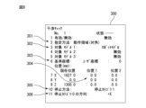
- FIG. 8 is a diagram showing a first example of a UI (user interface) screen for setting the specified area and stopping method.
- the UI screen 300 is provided as a function by the area setting section 202 and the stopping method setting section 203.
- the UI screen 300 may be displayed on the display screen of the display unit 43 of the external input device 40, and operation input to the UI screen may be received via an operation on the operation unit 44.
- the UI screen 300 has an area specification field 301 in which either an operation area or a restricted area can be specified as the specified area.
- FIG. 8 shows an example in which a motion area is specified as the specified area.
- the position of the motion area can be set in the position specification field 304.
- the target model specification field 302 a robot model for interference checking as shown in FIG. 2 can be specified.
- the UI screen 310 further includes a specification field 305 for specifying the stopping method, a specification field 306 for specifying the movement direction of stop category 0, and a specification field 306 for specifying the movement direction when detecting the movement direction. It has a field 306 and a designation field 303 for designating the reference coordinate system when detecting the motion direction.
- the stop category 0 is used only for the direction specified in the specification column 306 for specifying the direction of stop category 0, and the stop category specified in the stop method specification column 305 is used for other directions. In the case of the settings shown in FIG. 8, only the +X direction is stopped in stop category 0, and all other directions are stopped in stop category 1.
- the options that can be specified in the stop category specification field 306 may be “none”, “+X”, “+Y”, “+Z”, “-X”, “-Y”, and “-Z”. .
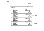
- FIG. 9 is a diagram showing a second example of the UI screen for setting the specified area and stopping method.
- These UI screens are provided as functions by the area setting section 202 and the stop method setting section 203. These UI screens may be displayed on the display screen of the display unit 43 of the external input device 40, and operation inputs to the UI screen may be received via operations on the operation unit 44.
- the UI screen 310 shown on the left side of FIG. 9 mainly relates to setting of a specified area.
- the UI screen 320 shown on the right side of FIG. 9 is a setting screen regarding detailed settings of the stopping method.
- the UI screen 310 has an area specification field 311 in which either an operation area or a restricted area can be specified as the specified area.
- FIG. 9 shows an example in which a motion area is specified as the specified area.
- the position of the motion area can be set in the position specification field 312.
- a robot model for interference check as shown in FIG. 2 can be specified.
- the UI screen 310 includes a stop method specification field 314. By performing an operation of selecting the stop method specification field 314, a UI screen 320 for making detailed settings for the stop method can be called up. As shown in FIG. 9, the UI screen 320 is configured so that different stopping methods can be set depending on the direction of operation. On the UI screen 320, each stopping method is as follows: (1) Stop category (designation field 321) (2) Direction of robot movement at the time of interference (designation field 322) (3) Reference coordinate system when detecting the movement direction (designation field 323) can be set.
- Stop method 1 Stop category 0, operation direction is +X direction, reference coordinate system is world coordinate system
- Stop method 2 Stop category 0, operation direction is +Y direction, reference coordinate system is user coordinate system 1
- Stopping method 3 Setting to not stop, operating direction is +Z direction, reference coordinate system is user coordinate system 2
- Stop method 4 Stop category 1, operating direction is -X direction, reference coordinate system is user coordinate system 3
- the component of the movement direction of the robot 10 when the robot 10 interferes with the outer surface of the movement area or the restricted area may be detected, and the stop category may be determined based on the detected component.
- the robot control device 20 can determine the stop category using the following procedure. (A1) Detect interference between the robot and the outer surface of the operating area or the restricted area. (A2) Detect multiple components in the motion direction. (A3) Obtain set stop categories for all motion direction components detected in step (A2). (A4) The stop category with the highest priority among the stop categories obtained in step (A3) is adopted.
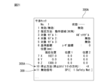
- FIG. 10 shows a situation where two components are required as the movement direction when the robot 10 deviates from the movement area R101.
- +Y and -X components are obtained as components in the robot's motion direction V.
- FIG. 11 shows the setting contents (UI screen 320A) of the stopping method used in this example.
- the motion direction components obtained in the situation of FIG. 10 are +Y component and -X component, so as described in the columns 325 and 326 in FIG. 11, the stop category obtained in the above procedure (A3) is: They are stop category 0 and stop category 1.
- the priority of stop categories for example, a high priority is assigned to a stop category that should be given more importance from the viewpoint of safety. In this case, stop category 0 has a higher priority than stop category 1. Therefore, in this case, stop category 0 is adopted in step (A4), and the robot 10 is stopped in stop category 0.
- the robot 10 is brought to an emergency stop in stop category 0, ensuring the safety of the operator OP. Ru.
- FIG. 12 shows a situation in which a state in which the robot model 101M set in the robot 10 interferes with the outer surface of the motion region R101 (the robot model 101M deviates from the motion region R101) is detected. In this way, by detecting interference using the robot model 101M, the calculation load can be reduced.
- the robot control device 20A according to the second embodiment detects which surface the robot 10 interferes with among the surfaces constituting the outer surface of the operating area or the restricted area, and selects a stop category according to the surface where the interference occurs. This is a configuration that allows you to set.
- FIG. 13 is a functional block diagram of a robot control device 20A according to the second embodiment.
- the same functional blocks as those of the robot control device 20 according to the first embodiment shown in FIG. 4 are given the same reference numerals.
- the robot control device 20A includes a motion control section 201, an area setting section 202, a stopping method setting section 203A, a position calculation section 204, an interference detection section 205, and an interference surface detection section 209. , and a stop portion 207A.
- the stopping method setting unit 203A can provide a function for setting a stopping category for each outer surface of the operating area or restricted area.
- the interference surface detection unit 209 functions as an operation state detection unit that detects the operation state of the robot 10 when interference is detected by the interference detection unit 205.
- the interference surface detection unit 209 detects which surface of the outer surface of the operating region or the restricted region the robot 10 has interfered with when interference between the robot 10 and the outer surface of the operating region or the restricted region is detected.
- the stop unit 207A stops the robot 10 according to the stop category set for the surface detected by the interference surface detection unit 209.
- identification information may be assigned to each side as shown in FIGS. 14 and 15.
- FIG. 14 shows an example in which identification numbers 1 to 6 are assigned to each of the front, right side, back surface, left side, bottom surface, and top surface when a rectangular parallelepiped operating region R1 is set.
- identification numbers 1 to 6 are shown by numbers with circles, respectively.
- FIG. 15 shows a state in which an octagonal prism-shaped operating area R2 is set around the robot, identification numbers 1 to 8 are assigned to the eight sides, and identification numbers 9 and 10 are assigned to the top and bottom surfaces, respectively.
- identification numbers 1 to 10 are each shown with a circled number.
- the interference surface detection unit 209 and the stop unit 207A can identify each surface on the outer surface of the specified area via these identification numbers. In this way, by assigning identification information to each surface on the outer surface that makes up the specified area and allowing identification of the surface, even if the specified area is set as a polyhedron, the stop category for each surface can be specified efficiently. can be done.
- FIG. 16A shows a state in which a rectangular parallelepiped-shaped operating area R101 is set, and when the lower side in the figure is the front side, identification numbers 1 to 4 are assigned to the front, right side, back, and left side of the operating area R101, respectively. shows.
- the identification numbers are each shown as a number with a circle.
- stop category 0 is set to the surface with identification number 2 (right side surface), and stop category 1 is set to the other surfaces.
- FIG. 16A illustrates a situation in which the robot 10 deviates from the operating range R101 while interfering with the surface with identification number 2 (right side surface).
- the robot 10 is stopped in stop category 0, which is assigned to the face with identification number 2 (right side).
- the robot 10 moves in a direction approaching the operator OP and deviates from the operating range R101, so the safety of the operator OP is reliably ensured.
- FIG. 16B illustrates a situation in which the robot 10 deviates from the operating range R101 while interfering with the surface with identification number 4 (left side surface).
- the robot 10 is stopped in stop category 1, which is assigned to the surface with identification number 4 (left side surface).
- the robot 10 moves in the direction away from the operator OP and deviates from the operating range R101, so that the safety of the operator OP is maintained and a load on the robot 10 is avoided.
- FIGS. 17A and 17B show an example of the operation when assigning an identification number to each surface forming the outer surface of the restricted area.
- identification numbers 1 to 4 are assigned to the front surface, right side surface, back surface, and left side, respectively, with the lower side in the figure as the front side.
- stop category 0 is set to the surface with identification number 4 (left side surface), and stop category 1 is set to the other surfaces.
- FIG. 17A shows a situation where the robot 10 interferes with the surface of identification number 4 (left side surface) of the restricted area R102 and enters the restricted area R102.
- the robot 10 is stopped in stop category 0, which is set on the surface with identification number 4 (left side).
- the operator OP is on the right side of the restricted area R102. Therefore, in a situation where the robot 10 enters the restricted area R102 to approach the operator OP as shown in FIG. 17A, the robot 10 is stopped in stop category 0, and the safety of the operator OP is ensured. becomes.
- FIG. 17B shows a situation where the robot 10 interferes with the surface of identification number 2 (right side) of the restricted area R103 and enters the restricted area R103.
- the robot 10 is stopped in stop category 1, which is set on the side with identification number 2 (right side).
- the operator OP is on the right side of the restricted area R103. Therefore, in a situation where the robot 10 enters the restricted area R103 away from the operator OP as shown in FIG. 17B, the robot 10 is stopped in stop category 1, thereby maintaining the safety of the operator OP. , a load on the robot 10 is avoided.
- FIG. 18 is a diagram showing an example of a UI (user interface) screen for setting the specified area and stopping method in the second embodiment.
- These UI screens are provided as functions by the area setting section 202 and the stopping method setting section 203A.
- These UI screens may be displayed on the display screen of the display unit 43 of the external input device 40, and operation inputs to the UI screen may be received via operations on the operation unit 44.
- the UI screen 410 shown on the left side of FIG. 18 mainly relates to setting of a specified area.
- the UI screen 420 shown on the right side of FIG. 18 is a setting screen regarding detailed settings of the stopping method.
- the UI screen 410 has designation fields similar to the designation fields 311 to 314 in the UI screen 310 shown in FIG.
- the UI screen 410 includes a stop method specification field 411.
- a UI screen 420 for setting details of the stopping method can be called up.
- the UI screen 420 is configured so that a plurality of stopping methods can be set depending on the surface with which the robot interferes.
- each stopping method is as follows: (1) Stop category (designation field 421) (2) Surface where the robot interferes (designation field 422) can be set.
- the stopping method is as follows: (1) Stop category (designation field 421) (2) Surface where the robot interferes (designation field 422) can be set.
- the stopping method is as follows: (1) Stop category (designation field 421) (2) Surface where the robot interferes (designation field 422) can be set.
- Stop method 1 Designated surface 1 (identification number 1)
- stop category 0 Stop method 2: Designated surface 2 (identification number 2)
- Stopping method 3 Specified surface 3 (identification number 3)
- Stop method 4 without stopping Specified surface 4 (identification number 4), Stop category 1
- the robot control device 20B according to the third embodiment can enable or disable the restricted area, enables the restricted area when the operator enters the restricted area, and controls the movement of the robot 10 within the restricted area at that time.
- the robot is configured to stop in a stop category depending on the direction.
- the above functions of the robot control device 20B include arranging a sensor to detect when a person enters the restricted area, inputting a signal from the sensor to the robot control device 20B, and detecting the entry of a person into the restricted area. This can be achieved by performing control to enable the restricted area when the restricted area is activated.
- Various sensors such as a light curtain, a safety mat, and an area sensor can be used as the sensor for detecting the entry of a person into the restricted area.
- inputs from I/O devices such as sequencers may also be used as signals via the input/output interface 45.
- FIG. 19 is a functional block diagram of a robot control device 20B according to the third embodiment.
- the same reference numerals are assigned to the same functional blocks as those of the robot control device 20 according to the first embodiment.
- the robot control device 20B includes a region setting section 202B, a stopping method setting section 203, a position calculation section 204, an interference detection section 205B, and an operation direction detection section as functional blocks related to safety functions. 206 and a stop section 207.
- a detection signal from the sensor 80 for detecting that a person has entered the restricted area is input to the interference detection unit 205B.
- the area setting unit 202B is configured to provide a function for setting the specified area to be valid or invalid.
- the interference detection unit 205B determines that the restricted area is valid when the sensor 80 detects a person entering the restricted area, and operates when interference between the robot 10 and the restricted area is detected in the situation. The direction detection unit 206 is notified of this. On the other hand, if the sensor 80 does not detect a person entering the restricted area, the interference detection unit 205B considers the restricted area to be invalid.
- the motion direction detection section 206 functions as a motion state detection section that detects the motion state of the robot 10 when interference is detected by the interference detection section 205B.
- the motion direction detection unit 206 detects the motion direction of the robot 10 when a person enters the restricted area in a situation where interference between the robot 10 and the restricted area is detected.
- the stopping unit 207 stops the robot 10 using stop control according to the operating direction of the robot 10 when a person enters the restricted area.
- FIGS. 20A to 20C A specific example of operation will be described with reference to FIGS. 20A to 20C.
- a restricted area R110 is set on the front side of the robot 10, and the operator OP is in a situation where there is a possibility of entering the restricted area R110.
- stop category 0 is set in the +X direction as the movement direction
- stop category 1 is set in the -X direction as the movement direction. shall be taken as a thing.
- the interference detection unit 205B regards the restricted area R110 as invalid and does not check to detect interference between the robot 10 and the restricted area R110.
- stop control is not executed when the robot 10 interferes with the restricted area R110, but the safety of the operator OP is maintained, and a load on the robot 10 due to the stop control is avoided.
- FIG. 20B shows a situation where the operator OP has entered the restricted area R110.
- the sensor 80 detects the operator OP's intrusion into the restricted area R110, and the restricted area R110 is activated.
- the robot 10 has entered the restricted area R110 and its movement direction is the +X direction, so the robot 10 is brought to an emergency stop due to stop category 0. This ensures the safety of the operator OP.
- FIG. 20C shows a situation where the operator OP has entered the restricted area R110.
- the sensor 80 detects the operator OP's intrusion into the restricted area R110, and the restricted area R110 is activated.
- the robot 10 has entered the restricted area R110 and its movement direction is the -X direction, and the robot 10 is stopped according to stop category 1.
- the load on the robot 10 is reduced while the safety of the operator OP is maintained.
- FIG. 21 shows an example of a UI screen used in settings in the third embodiment.
- the UI screen 300A is provided as a function by the area setting section 202B and the stopping method setting section 203.
- the UI screen 300A may be displayed on the display screen of the display unit 43 of the external input device 40, and operation inputs to the UI screen 300A may be received via operations on the operation unit 44.
- the UI screen 300A used in this embodiment is the same as the UI screen 300 in the first embodiment described with reference to FIG. It may be realized.
- the UI screen 300A shows an example in which settings are made to designate a signal from a safety mat as the signal for invalidating the restricted area.
- the interference detection unit 205B can specify the state of the signal from the sensor 80 in which the restricted area is invalidated. Note that in the UI screen 300A, the direction of stop category 0 is specified in the specification field 305A for specifying the stop method.
- a restricted area is set as a designated area and stop control is performed by disabling or enabling the restricted area based on a signal from the sensor 80.
- an operating area may be set as a designated area.
- a configuration may also be adopted in which the sensor 80 detects the intrusion of a person into the operating area, and the operating area is disabled or enabled based on the signal from the sensor 80 to perform the stop control. In this case, as in the above-described embodiment, it is possible to implement stop control that reduces the burden on the robot while ensuring the safety of the operator.
- the valid/invalid area is determined for the area where the robot is stopped according to the stop category corresponding to the movement direction of the robot 10 when interference with the outer surface of the movement area or the restricted area is detected.
- the sensor 80 A configuration may also be adopted in which the stop control is performed by disabling or enabling the operating region based on the signal. In this case, as in the above-described embodiment, it is possible to implement stop control that reduces the burden on the robot while ensuring the safety of the operator.
- the functional arrangement shown in the functional block diagrams (FIGS. 4, 13, and 19) of the robot control device in the above-described embodiments is merely an example, and there may be various modifications to the arrangement of these functional blocks.
- the overall function that combines the function of the teaching pendant as an external input device and the function of the robot control device can also be defined as the robot control device.
- the functional blocks of the robot control device shown in FIG. 4, FIG. 13, and FIG. It may also be realized by a hardware-based configuration such as a specific integrated circuit.
- a program that executes various processes such as a procedure for determining a stop category in the above-described embodiments can be stored in various computer-readable recording media (e.g., ROM, EEPROM, semiconductor memory such as flash memory, magnetic recording medium, etc.). It can be recorded on optical disks such as CD-ROM and DVD-ROM).
- ROM read-only memory
- EEPROM electrically erasable programmable read-only memory
- optical disks such as CD-ROM and DVD-ROM
Landscapes
- Engineering & Computer Science (AREA)
- Robotics (AREA)
- Mechanical Engineering (AREA)
- Manipulator (AREA)
- Numerical Control (AREA)
Priority Applications (6)
| Application Number | Priority Date | Filing Date | Title |
|---|---|---|---|
| PCT/JP2022/025799 WO2024004043A1 (ja) | 2022-06-28 | 2022-06-28 | ロボット制御装置 |
| CN202280096915.XA CN119343214A (zh) | 2022-06-28 | 2022-06-28 | 机器人控制装置 |
| US18/875,164 US20250375882A1 (en) | 2022-06-28 | 2022-06-28 | Robot control device |
| DE112022007128.1T DE112022007128T5 (de) | 2022-06-28 | 2022-06-28 | Robotersteuervorrichtung |
| JP2024530130A JP7820515B2 (ja) | 2022-06-28 | 2022-06-28 | ロボット制御装置 |
| TW112119934A TW202400387A (zh) | 2022-06-28 | 2023-05-29 | 機器人控制裝置 |
Applications Claiming Priority (1)
| Application Number | Priority Date | Filing Date | Title |
|---|---|---|---|
| PCT/JP2022/025799 WO2024004043A1 (ja) | 2022-06-28 | 2022-06-28 | ロボット制御装置 |
Publications (1)
| Publication Number | Publication Date |
|---|---|
| WO2024004043A1 true WO2024004043A1 (ja) | 2024-01-04 |
Family
ID=89382240
Family Applications (1)
| Application Number | Title | Priority Date | Filing Date |
|---|---|---|---|
| PCT/JP2022/025799 Ceased WO2024004043A1 (ja) | 2022-06-28 | 2022-06-28 | ロボット制御装置 |
Country Status (6)
| Country | Link |
|---|---|
| US (1) | US20250375882A1 (https=) |
| JP (1) | JP7820515B2 (https=) |
| CN (1) | CN119343214A (https=) |
| DE (1) | DE112022007128T5 (https=) |
| TW (1) | TW202400387A (https=) |
| WO (1) | WO2024004043A1 (https=) |
Cited By (1)
| Publication number | Priority date | Publication date | Assignee | Title |
|---|---|---|---|---|
| US20250189962A1 (en) * | 2023-04-06 | 2025-06-12 | Agility Robotics | Differential Communication With Robots in a Fleet and Related Technology |
Citations (5)
| Publication number | Priority date | Publication date | Assignee | Title |
|---|---|---|---|---|
| JP2004243427A (ja) * | 2003-02-12 | 2004-09-02 | Yaskawa Electric Corp | ロボット制御装置およびロボット制御方法 |
| JP2010188515A (ja) * | 2009-01-26 | 2010-09-02 | Fanuc Ltd | 人間とロボットとの協調動作領域を有する生産システム |
| JP2011125975A (ja) * | 2009-12-18 | 2011-06-30 | Denso Wave Inc | ロボットの干渉回避装置 |
| JP2011212831A (ja) * | 2010-03-15 | 2011-10-27 | Yaskawa Electric Corp | ロボットシステム |
| US20210053224A1 (en) * | 2019-08-23 | 2021-02-25 | Paul Jakob Schroeder | Safe operation of machinery using potential occupancy envelopes |
Family Cites Families (2)
| Publication number | Priority date | Publication date | Assignee | Title |
|---|---|---|---|---|
| JP2000202790A (ja) | 1999-01-14 | 2000-07-25 | Sharp Corp | ロボット装置 |
| JP7011910B2 (ja) | 2017-09-01 | 2022-01-27 | 川崎重工業株式会社 | ロボットシステム |
-
2022
- 2022-06-28 CN CN202280096915.XA patent/CN119343214A/zh active Pending
- 2022-06-28 JP JP2024530130A patent/JP7820515B2/ja active Active
- 2022-06-28 DE DE112022007128.1T patent/DE112022007128T5/de active Pending
- 2022-06-28 US US18/875,164 patent/US20250375882A1/en active Pending
- 2022-06-28 WO PCT/JP2022/025799 patent/WO2024004043A1/ja not_active Ceased
-
2023
- 2023-05-29 TW TW112119934A patent/TW202400387A/zh unknown
Patent Citations (5)
| Publication number | Priority date | Publication date | Assignee | Title |
|---|---|---|---|---|
| JP2004243427A (ja) * | 2003-02-12 | 2004-09-02 | Yaskawa Electric Corp | ロボット制御装置およびロボット制御方法 |
| JP2010188515A (ja) * | 2009-01-26 | 2010-09-02 | Fanuc Ltd | 人間とロボットとの協調動作領域を有する生産システム |
| JP2011125975A (ja) * | 2009-12-18 | 2011-06-30 | Denso Wave Inc | ロボットの干渉回避装置 |
| JP2011212831A (ja) * | 2010-03-15 | 2011-10-27 | Yaskawa Electric Corp | ロボットシステム |
| US20210053224A1 (en) * | 2019-08-23 | 2021-02-25 | Paul Jakob Schroeder | Safe operation of machinery using potential occupancy envelopes |
Cited By (1)
| Publication number | Priority date | Publication date | Assignee | Title |
|---|---|---|---|---|
| US20250189962A1 (en) * | 2023-04-06 | 2025-06-12 | Agility Robotics | Differential Communication With Robots in a Fleet and Related Technology |
Also Published As
| Publication number | Publication date |
|---|---|
| JP7820515B2 (ja) | 2026-02-25 |
| TW202400387A (zh) | 2024-01-01 |
| JPWO2024004043A1 (https=) | 2024-01-04 |
| DE112022007128T5 (de) | 2025-03-13 |
| CN119343214A (zh) | 2025-01-21 |
| US20250375882A1 (en) | 2025-12-11 |
Similar Documents
| Publication | Publication Date | Title |
|---|---|---|
| EP1644782B1 (en) | Multiple robot arm tracking and mirror jog | |
| KR101644758B1 (ko) | 관절형 로봇을 위한 이벤트 기반의 여유 각도 구성 | |
| Kim et al. | Eclipse II: A new parallel mechanism enabling continuous 360-degree spinning plus three-axis translational motions | |
| TWI611883B (zh) | 產業用遠端操作機器人系統 | |
| US20080231221A1 (en) | Arm-equipped mobile robot and method for controlling the same | |
| JP5872894B2 (ja) | ロボット動作教示支援装置及び方法 | |
| KR101498836B1 (ko) | 7축 다관절 로봇의 제어 장치 및 교시 방법 | |
| CN110026977A (zh) | 机器人控制装置及自动组装系统 | |
| JP2020516475A (ja) | 産業ロボットマニピュレータのための教示モード衝突回避システムおよび方法 | |
| JP6450737B2 (ja) | ロボットシステム | |
| CN106891321A (zh) | 作业装置 | |
| JPH0248400B2 (https=) | ||
| WO2024004043A1 (ja) | ロボット制御装置 | |
| JP2017205819A (ja) | ロボット、制御装置、及びロボットシステム | |
| JP2009066738A (ja) | ロボットの教示装置 | |
| Sukhorukov et al. | Methodology for Implementing Some of Collaborative Functions on an Industrial Robot | |
| JP7761657B2 (ja) | シミュレーション装置 | |
| CN116460840A (zh) | 具有多个运动区段的多轴运动系统的安全导向的监控的规划 | |
| JP5721167B2 (ja) | ロボット制御装置 | |
| US20250339966A1 (en) | Robot control device | |
| JP7846203B2 (ja) | ロボット制御装置 | |
| JP7529920B1 (ja) | ロボットの動作を制御する装置及び方法、動作プログラムを生成する装置及び方法、コンピュータプログラム、並びに動作プログラム | |
| JP7462046B2 (ja) | ロボットシステム | |
| KR20230112814A (ko) | 펜스리스 안전기능 협동 로봇 | |
| CN118103177A (zh) | 处理工业机器人的安全的方法、控制系统和机器人系统 |
Legal Events
| Date | Code | Title | Description |
|---|---|---|---|
| 121 | Ep: the epo has been informed by wipo that ep was designated in this application |
Ref document number: 22949319 Country of ref document: EP Kind code of ref document: A1 |
|
| WWE | Wipo information: entry into national phase |
Ref document number: 2024530130 Country of ref document: JP |
|
| WWE | Wipo information: entry into national phase |
Ref document number: 202280096915.X Country of ref document: CN |
|
| WWE | Wipo information: entry into national phase |
Ref document number: 18875164 Country of ref document: US |
|
| WWE | Wipo information: entry into national phase |
Ref document number: 112022007128 Country of ref document: DE |
|
| WWP | Wipo information: published in national office |
Ref document number: 202280096915.X Country of ref document: CN |
|
| WWP | Wipo information: published in national office |
Ref document number: 112022007128 Country of ref document: DE |
|
| 122 | Ep: pct application non-entry in european phase |
Ref document number: 22949319 Country of ref document: EP Kind code of ref document: A1 |
|
| WWP | Wipo information: published in national office |
Ref document number: 18875164 Country of ref document: US |