WO2024003986A1 - モータ駆動装置 - Google Patents
モータ駆動装置 Download PDFInfo
- Publication number
- WO2024003986A1 WO2024003986A1 PCT/JP2022/025561 JP2022025561W WO2024003986A1 WO 2024003986 A1 WO2024003986 A1 WO 2024003986A1 JP 2022025561 W JP2022025561 W JP 2022025561W WO 2024003986 A1 WO2024003986 A1 WO 2024003986A1
- Authority
- WO
- WIPO (PCT)
- Prior art keywords
- component
- hole
- motor drive
- drive device
- protrusion
- Prior art date
- Legal status (The legal status is an assumption and is not a legal conclusion. Google has not performed a legal analysis and makes no representation as to the accuracy of the status listed.)
- Ceased
Links
Images





Classifications
-
- H—ELECTRICITY
- H05—ELECTRIC TECHNIQUES NOT OTHERWISE PROVIDED FOR
- H05K—PRINTED CIRCUITS; CASINGS OR CONSTRUCTIONAL DETAILS OF ELECTRIC APPARATUS; MANUFACTURE OF ASSEMBLAGES OF ELECTRICAL COMPONENTS
- H05K5/00—Casings, cabinets or drawers for electric apparatus
- H05K5/10—Casings, cabinets or drawers for electric apparatus comprising several parts forming a closed casing
- H05K5/13—Casings, cabinets or drawers for electric apparatus comprising several parts forming a closed casing assembled by screws
Definitions
- the present invention relates to a motor drive device that drives a motor.
- a motor drive device includes a first component and a second component.
- the second part is fixed to the first part by inserting the shaft into the first hole made in the first part through the second hole made in the second part.
- the first part and the second part are provided with alignment structures for aligning the second part with respect to the first part.
- a margin is provided in the alignment structure, with the limit being a range in which the first hole can be visually recognized through the second hole.
- FIG. 1 is a perspective view of a motor drive device according to this embodiment.
- FIG. 2 is a perspective view showing a state in which the board is removed from the case in FIG. 1.
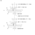
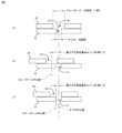
- FIG. 3 is a sectional view showing the protrusion and receiving hole of FIG. 1.
- FIG. 4 is a sectional view showing the screw hole and through hole in FIG. 1.
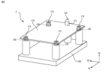
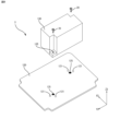
- FIG. 5 is a perspective view schematically showing a case and a board of the motor drive device according to the present embodiment.
- FIG. 6 is a plan view of the second part of FIG. 5.
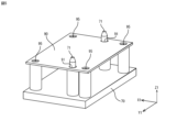
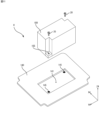
- FIG. 7 is a perspective view schematically showing a case and a board of a motor drive device according to a second embodiment.
- FIG. 8 is a plan view of the second part of FIG. 7.
- FIG. 9 is an exploded perspective view of the motor drive device according to the third embodiment.
- 10 is a plan view of the second part of FIG. 9.
- FIG. 11 is an exploded perspective view of the motor drive device according to the fourth embodiment.
- One feature of the motor drive device is that an alignment structure is directly provided on the components constituting the motor drive device so that the assembly work of the motor drive device can be easily performed. Thereby, the parts can be easily aligned without using a separate alignment jig during the assembly operation, so that the assembly operation of the motor drive device can be performed efficiently.
- a screw is employed as a fastening member that fastens two components that constitute a motor drive device.
- the fastening member is not limited to a screw, and for example, a shaft body such as a bolt or a rivet may be used.
- one of the first component and the second component constituting the motor drive device has a screw hole (corresponding to the first hole) for fastening a screw, and the other has a screw hole for fastening a screw (corresponding to the first hole). It has a through hole (corresponding to the second hole).
- a screw is inserted through a through hole formed in the second component into a screw hole formed in the first component, and is fastened to fix the second component to the first component.
- the screw hole is replaced by a through hole for passing the rivet. In this way, depending on the fastening member used, a screw hole, a through hole, etc. can be employed as the first hole.
- a motor drive device will be described as an example.
- embodiments of the present invention can be broadly applied to various devices and mechanisms having two parts fixed to each other by using shafts such as screws, bolts, rivets, etc.
- FIG. 1 is a perspective view showing a motor drive device according to a first embodiment.
- FIG. 2 is an exploded perspective view of the motor drive device of FIG. 1.
- the motor drive device 1 includes a box-shaped case 10 that is rectangular in plan view with an open top, a case cover 50 that covers the top opening of the case 10, and a motor (not shown). ) on which electronic components (not shown) are mounted.
- the axis parallel to the short side of the case 10 is the X1 axis
- the axis parallel to the long side of the case 10 is the Y1 axis
- the axis parallel to the thickness direction of the case 10 orthogonal to the X1 axis and the Y1 axis is the Z1 axis.
- the direction along the Z1 axis is called the up-down direction.
- the direction in which the board 30 is attached to the case 10 (mounting direction) is parallel to the Z1 axis.
- the case 10 includes a plurality of upwardly protruding protrusions 11, here two protrusions 11, and screw holes 13 into which screws 20 for fixing the board 30 to the case 10 are fastened. and a screw hole 15 into which a screw 40 for fixing the case cover 50 to the case 10 is fastened.
- the screw holes 13 for fastening the board are referred to as the screw holes 13 for the board
- the screw holes 15 for the case cover are referred to as the screw holes 15 for the cover.
- the board screw hole 13 and the cover screw hole 15 are provided with their center lines parallel to the Z1 axis.
- the substrate 30 has two receiving holes 31 that respectively receive the two protrusions 11 provided on the case 10.
- the receiving hole 31 is a through hole that vertically passes through the substrate 30, and is provided with its center line parallel to the Z axis.
- the board 30 has a circular through hole 33 into which a screw used for fixing the board 30 to the case 10 is inserted.
- the protrusion 11 is typically configured to have a cylindrical shape that is longer than the thickness of the substrate 30.
- the outer diameter of the protrusion 11 is desirably larger than the inner diameter of the through hole 33.
- the upper portion of the projection 11 has a tapered shape that becomes thinner toward the tip.
- the entire protrusion 11 may be formed into a cylindrical body that tapers gradually toward the tip.
- the opening of the receiving hole 31 on the back side of the substrate 30 facing the case 10 may be made larger than the opening of the receiving hole 31 on the front side of the substrate 30.
- the receiving hole 31 has an inner diameter UD (UDmax, UDmin) larger than the maximum outer diameter TD of the projection 11.
- the board screw hole 13 of the case 10 may no longer be visible through the through hole 33 of the board 30 after the alignment work.
- the through holes 33 of the board 30 may match the board screw holes 13 of the case 10 in some cases. In such a case, there is no need to adjust the position of the board 30 with respect to the case 10 during the screw tightening operation, so that a decrease in the work efficiency of the screw tightening operation can be suppressed.
- the inner diameter of the receiving hole 31 constituting the alignment structure is designed to achieve both alignment work efficiency and screw tightening work efficiency.
- the upper limit value (maximum inner diameter UDmax) and lower limit value (UDmin) of the inner diameter UD of the receiving hole 31 were determined as follows.
- the upper limit value (maximum inner diameter UDmax) and lower limit value (UDmin) of the inner diameter UD of the receiving hole 31 are determined based not only on the outer diameter TD of the protrusion 11 provided on the case 10 but also on the board screw hole 13 provided on the board 30. Another feature of the first embodiment is that it is defined by the inner diameter ND of the through hole 33 provided in the case 10 and the inner diameter SD of the through hole 33 provided in the case 10.
- the maximum inner diameter UDmax of the receiving hole 31 is set to a value obtained by adding twice the maximum margin Mmax to the outer diameter TD of the protrusion 11.
- the maximum margin Mmax corresponds to the maximum value (maximum allowable shift amount) Smax of the allowable positional shift amount of the through hole 33 with respect to the board screw hole 13.
- the maximum allowable deviation amount Smax can be calculated using the formula ((SD+ND)/2). That is, the maximum inner diameter UDmax of the receiving hole 31 is set to a value that is the sum of the inner diameter SD of the through hole 33 and the inner diameter ND of the board screw hole 13.
- the inner diameter SD of the through hole 33 is larger than the inner diameter ND of the board screw hole 13.
- the maximum allowable displacement amount Smax corresponds to a limit value of the amount of displacement of the through hole 33 with respect to the substrate screw hole 13, which allows an operator to visually recognize a portion of the substrate screw hole 13 through the through hole 33.
- the operator can at least visually recognize the board screw hole 13 through the through hole 33.
- the operator can adjust the board 3 to the case 10 in order to match the through holes 33 with the board screw holes 13. You can quickly figure out in which direction you should move it. Therefore, compared to the case where the board screw hole 13 cannot be visually recognized through the through hole 33, a decrease in the work efficiency of the screw tightening work can be suppressed.
- the minimum inner diameter UDmin of the receiving hole 31 is set to a value obtained by adding twice the minimum margin Mmin to the outer diameter TD of the protrusion 11.
- the minimum margin Mmin corresponds to the minimum value (minimum allowable deviation) Smin of the allowable positional deviation of the through hole 33 with respect to the board screw hole 13.
- the minimum allowable deviation amount Smin can be calculated using the formula ((SD-ND)/2). That is, the minimum inner diameter UDmin of the receiving hole 31 is set to a value that is the sum of the difference between the inner diameter SD of the through hole 33 and the inner diameter ND of the board screw hole 13.
- the minimum allowable deviation amount Smin corresponds to the maximum value of the amount of positional deviation of the through hole 33 with respect to the board screw hole 13, which allows the operator to visually check the entire board screw hole 13 through the through hole 33.
- the operator can see the entire board screw hole 13 through the through hole 33 after the board 30 is aligned with the case 10.
- the screw tightening work of the board 30 to the case 10 can be performed without moving the board 30 and in the same state after alignment. In other words, the operator can perform screw tightening work with the same workability as when the inner diameter UD of the receiving hole 31 matches the outer diameter TD of the protrusion 11.
- the inner diameter UD of the receiving hole 31 is larger than the outer diameter TD of the protrusion 11, it is easier to connect the receiving hole 31 to the protrusion 11 than when the inner diameter UD of the receiving hole 31 matches the outer diameter TD of the protrusion 11. It is easy to insert, and a decrease in work efficiency in positioning the board 30 with respect to the case 10 can be suppressed.
- the inner diameter UD of the receiving hole 31 that constitutes the alignment structure is set to be more than the minimum inner diameter UDmin and less than the maximum inner diameter UDmax, screw tightening work is made easier than when the board screw hole 13 is not visible through the through hole 33.
- a decrease in work efficiency can be suppressed, and a decrease in work efficiency in alignment work can be suppressed compared to the case where the inner diameter UD of the receiving hole 31 matches the outer diameter TD of the protrusion 11. In other words, both the workability of positioning work and the workability of screw tightening work can be achieved.
- the inner diameter UD of 31 may be less than the maximum inner diameter UDmax, and may not be greater than or equal to the minimum inner diameter UDmin.
- the two receiving holes 31 provided in the substrate 30 are arranged at positions that satisfy three arrangement conditions.
- the arrangement conditions will be explained below with reference to FIGS. 5 and 6.
- the arrangement conditions will be explained below with reference to FIGS. 5 and 6.
- the arrangement conditions will be explained below with reference to FIGS. 5 and 6.
- the rectangular plate-shaped second component 90 is aligned with the first component 70.
- the first component 70 schematically represents the case 10
- the second component 90 schematically represents the board 30.
- the protrusion 11 of the case 10 corresponds to the protrusion 71 of the first component 70
- the receiving hole 31 of the substrate 30 corresponds to the receiving hole 91 of the second component 90.
- the center position C1 of the second component 90 corresponds to the center position of the width and length of the second component 90.
- Arrangement Condition 1 The two receiving holes 91 are arranged at positions that are not axisymmetric with respect to an axis Xc1 passing through the center position C1 of the second part 90 and parallel to the short side of the second part 90.
- Arrangement Condition 2 The two receiving holes 91 are arranged at positions that are not axisymmetric with respect to an axis Yc1 that passes through the center position C1 of the second component 90 and is parallel to the long side of the second component 90.
- Arrangement Condition 3 The two receiving holes 91 are arranged at positions that are not symmetrical with respect to the center position C1 of the second component 90.
- the two receiving holes 91 are arranged in positions that satisfy the above three arrangement conditions. That is, when the second component 90 is placed upside down or with the front and back reversed relative to the first component 70, the protrusion 71 of the first component 70 does not pass through the receiving hole 91 of the second component 90 and interferes with the back surface. The second component 90 cannot be fixed to the first component 70 with screws. In other words, it is possible to physically avoid a situation where the second component 90 is attached to the first component 70 in the wrong direction.
- the following effects are achieved. That is, by directly providing the protrusion 11 and the receiving hole 31 that constitute the alignment structure on the case 10 and the substrate 30 that make up the motor drive device 1, the operator can use a separate jig for alignment. The case 10 and the board 30 can be aligned with each other with fewer man-hours, and the efficiency of the assembly work of the motor drive device 1 can be improved.
- the case 10 has the protrusion 11 and the substrate 30 has the receiving hole 31.
- the case 10 may have a receiving hole and the substrate 30 may have a protrusion. Even in such a case, the same effects as in the first embodiment can be achieved.
- the outer diameter of the protrusions be larger than the inner diameter of the screw holes.
- the motor drive device 1 according to the first embodiment has two sets of protrusions and receiving holes as alignment structures.
- the motor drive device 1 according to the first embodiment may have three or more sets of protrusions and receiving holes as the alignment structure.
- the position of the board 30 relative to the case 10 is uniquely determined compared to a configuration with two sets, so there is no risk of attaching the board 30 to the case 10 in the wrong direction. low.
- the protrusion 11 was formed into a cylindrical body, and the receiving hole 31 was formed into a circular shape that matched with the protrusion 11.
- the protrusion 11 is not limited to a cylindrical body, and may be a cylindrical body having an arbitrary cross-sectional shape such as an elliptical cylinder, an elongated cylinder, a polygonal cylinder, or the like.
- the motor drive device 2 according to the second embodiment will be described with reference to FIGS. 7 and 8.
- the first component 100 has one protrusion 101 that projects upward, and a screw hole 105 into which a screw for fixing the second component 110 to the first component 100 is fastened. and has.
- the protrusion 101 has a triangular prism shape.
- the upper portion of the projection 101 has a tapered shape that becomes thinner toward the tip.
- the second component 110 has a triangular receiving hole 111 for receiving the protrusion 101 and a through hole 115 through which a screw for fixing the second component 110 to the first component 100 is passed.
- the center position C of the second component 110 corresponds to the center position of the width and length of the second component 110.
- the inner diameter of the receiving hole 111 is larger than the outer diameter of the protrusion 101, and the maximum value (maximum inner diameter) and minimum value (minimum inner diameter) are determined using the same method as in the first embodiment. It can be calculated using
- the receiving hole 111 be arranged on the axis of symmetry of the second part 110 or at a position other than the center position of the second part 110.
- the receiving hole 111 is located at a position on the axis Xc2 that passes through the center position C2 of the second component 110 and is parallel to the short side of the second component 110, and at a position on the axis Xc2 that passes through the center position C2 of the second component 110 and It is arranged at a position on the axis Yc2 parallel to the long side of the component and at a position other than the center position C2 of the second component 110.
- the second component 110 when aligning the second component 110 with the first component 100 in order to match the through hole 115 of the second component 110 with the screw hole 105 of the first component 100, the second component 110 may be turned upside down. If the orientation is wrong, such as upside down, the receiving hole 111 of the second component 110 cannot be inserted into the protrusion 101 of the first component 100, and the protrusion 101 of the first component 100 will interfere with the second component 110. be able to.
- the second component 110 Since the number of protrusions provided on the first component 100 is one, it is also possible to attach the second component 110 in the wrong direction with respect to the first component 100. However, even if the second component 110 is attached to the first component 100 in the wrong direction, such as upside down or upside down, the second component 110 will clearly shift relative to the first component 100, and the first The through hole 115 of the second component 110 does not match the screw hole 105 of the component 100. Since the operator can easily understand that the second part 110 is aligned in the wrong direction, the situation where the second part 110 is attached to the first part 100 in the wrong direction is avoided. can be avoided.
- the motor drive device 2 according to the second embodiment has one set of protrusions 101 and receiving holes 111 that constitute an alignment structure.
- the motor drive device 1 according to the first embodiment has two sets of protrusions 11 and receiving holes 31 that constitute a positioning structure. Therefore, the second embodiment is superior to the first embodiment in terms of reducing the space in which the alignment structure is provided.
- the durability of the alignment structure specifically, the resistance to the load that the protrusions 11, 101 receive from the substrate 30 during alignment work, the two protrusions 11 can distribute the load. This embodiment is advantageous over the second embodiment with one protrusion 101.
- the alignment structure was composed of a protrusion and a receiving hole, each of which was provided on the two parts to be aligned.
- the configuration of the alignment structure is not limited to this. For example, from the perspective of aligning two parts without using an alignment jig, it is possible to align two parts so that only one part has an alignment structure. Can be configured.
- the motor drive device 3 includes a first component 120 having a plate shape and a second component 130 having a rectangular shape in plan view.
- the second part 130 is aligned with the first part 120 and fixed with the screw 20.
- the first component 120 has a plurality of protrusions 121, four in this case, as an alignment structure for aligning the second component 130 with respect to the first component 120.
- protrusion 121 is configured in a cylindrical shape.
- the four protrusions 121 are arranged on the surface of the first part 120 that the second part 130 contacts, at positions that satisfy the arrangement conditions.
- the outer periphery of the contact surface of the second component 130 that contacts the first component 120 is denoted by 130, and the center position of the second component 130, which is the center of the width and the center of the length of the second component 130, is denoted by the symbol C3. . Further, an axis passing through the center position C3 and parallel to the long side of the contact surface of the second component 130 is indicated by the symbol Xc3, and an axis passing through the center position C3 and parallel to the short side of the contact surface of the second component 130 is indicated by the symbol Xc3. Each is written as Yc3.
- Arrangement condition 1 The four protrusions 121 are arranged along the outer periphery 130a of the contact surface of the second component 130 that contacts the first component 120.
- Arrangement condition 2 The four protrusions 121 are arranged on four sides of the outer periphery 130a of the contact surface of the second component 130 that contacts the first component 120, respectively.
- Arrangement condition 3 An axis Xc3 passing through the center position C3 and parallel to the long side of the contact surface of the second component 130, an axis Yc3 passing through the center position C3 and parallel to the short side of the contact surface of the second component 130.
- At least two protrusions 121 are arranged in at least one of the four sections defined by .
- two protrusions 121 are arranged in each of two sections among the four sections.
- the second part 130 is fitted into the frame defined by the four protrusions 121 of the first part 120, and the second The location of part 130 may be defined. Further, by arranging the four protrusions 121 at positions that satisfy the arrangement conditions 1 and 2, it is possible to stop the aligned second component 130 from moving in the directions along the axis Xc3 and the axis Yc3. In addition, by arranging the four protrusions 121 at positions that satisfy arrangement conditions 1, 2, and 3, rotation of the aligned second part 130 around an axis perpendicular to the surface of the first part 120 is stopped. can do.
- the second component 130 can be aligned with the first component 120 without using an alignment jig, and the second component 130 can be aligned with the first component 120 without using an alignment jig.
- the second component 130 can be fixed to the first component 120 by inserting the screw 20 into the screw hole 125 and the through hole 135 of the second component 130 and tightening the screw 20 .
- the first component 120 which is one of the two components to be aligned, has a plurality of protrusions 121 as an alignment structure.
- the alignment structure that one of the two parts to be aligned has is not limited to a plurality of protrusions.
- the motor drive device 4 according to the fourth embodiment includes a first component 140 having a plate shape and a second component 150 having a rectangular shape in plan view.
- the second component 150 is aligned with the first component 140 and fixed with the screw 20 .
- the first component 140 has a recess 141 that receives the second component 150 as an alignment structure for aligning the second component 150 with respect to the first component 140 .
- the depression 141 has an inner peripheral surface shape that matches the outer peripheral surface shape of the contact surface of the second component 150 that contacts the first component 140 .
- the position of the second part 150 with respect to the first part 140 is defined, and the second part 150 is moved in the X4 direction and the Y4 direction with respect to the first part 140. Movement and rotation around the Z4 axis can be locked.
- the motor drive device 4 it is possible to align the second component 150 with respect to the first component 140 without using an alignment jig, and the second component 150 can be aligned with the first component 140 without using an alignment jig.
- the second component 150 can be fixed to the first component 140 by inserting the screw 20 into the screw hole 145 and the through hole 155 of the second component 150 and tightening the screw 20 .
Landscapes
- Engineering & Computer Science (AREA)
- Microelectronics & Electronic Packaging (AREA)
- Motor Or Generator Frames (AREA)
- Manufacture Of Motors, Generators (AREA)
Priority Applications (4)
| Application Number | Priority Date | Filing Date | Title |
|---|---|---|---|
| JP2024530090A JPWO2024003986A1 (https=) | 2022-06-27 | 2022-06-27 | |
| DE112022007076.5T DE112022007076T5 (de) | 2022-06-27 | 2022-06-27 | Motorantriebsvorrichtung |
| CN202280097541.3A CN119452742A (zh) | 2022-06-27 | 2022-06-27 | 马达驱动装置 |
| PCT/JP2022/025561 WO2024003986A1 (ja) | 2022-06-27 | 2022-06-27 | モータ駆動装置 |
Applications Claiming Priority (1)
| Application Number | Priority Date | Filing Date | Title |
|---|---|---|---|
| PCT/JP2022/025561 WO2024003986A1 (ja) | 2022-06-27 | 2022-06-27 | モータ駆動装置 |
Publications (1)
| Publication Number | Publication Date |
|---|---|
| WO2024003986A1 true WO2024003986A1 (ja) | 2024-01-04 |
Family
ID=89382213
Family Applications (1)
| Application Number | Title | Priority Date | Filing Date |
|---|---|---|---|
| PCT/JP2022/025561 Ceased WO2024003986A1 (ja) | 2022-06-27 | 2022-06-27 | モータ駆動装置 |
Country Status (4)
| Country | Link |
|---|---|
| JP (1) | JPWO2024003986A1 (https=) |
| CN (1) | CN119452742A (https=) |
| DE (1) | DE112022007076T5 (https=) |
| WO (1) | WO2024003986A1 (https=) |
Citations (5)
| Publication number | Priority date | Publication date | Assignee | Title |
|---|---|---|---|---|
| JPS62197633U (https=) * | 1986-06-04 | 1987-12-16 | ||
| JP2008283015A (ja) * | 2007-05-11 | 2008-11-20 | Kenwood Corp | 部品の取付構造 |
| JP2015060959A (ja) * | 2013-09-19 | 2015-03-30 | 日立オートモティブシステムズ株式会社 | 電子制御装置 |
| JP2019134648A (ja) * | 2018-02-02 | 2019-08-08 | 株式会社豊田自動織機 | インバータ |
| JP2020195274A (ja) * | 2019-05-30 | 2020-12-03 | 株式会社豊田自動織機 | 半導体装置 |
Family Cites Families (1)
| Publication number | Priority date | Publication date | Assignee | Title |
|---|---|---|---|---|
| JP2015229224A (ja) | 2014-06-06 | 2015-12-21 | パナソニックIpマネジメント株式会社 | 産業用ロボット |
-
2022
- 2022-06-27 JP JP2024530090A patent/JPWO2024003986A1/ja active Pending
- 2022-06-27 CN CN202280097541.3A patent/CN119452742A/zh active Pending
- 2022-06-27 WO PCT/JP2022/025561 patent/WO2024003986A1/ja not_active Ceased
- 2022-06-27 DE DE112022007076.5T patent/DE112022007076T5/de active Pending
Patent Citations (5)
| Publication number | Priority date | Publication date | Assignee | Title |
|---|---|---|---|---|
| JPS62197633U (https=) * | 1986-06-04 | 1987-12-16 | ||
| JP2008283015A (ja) * | 2007-05-11 | 2008-11-20 | Kenwood Corp | 部品の取付構造 |
| JP2015060959A (ja) * | 2013-09-19 | 2015-03-30 | 日立オートモティブシステムズ株式会社 | 電子制御装置 |
| JP2019134648A (ja) * | 2018-02-02 | 2019-08-08 | 株式会社豊田自動織機 | インバータ |
| JP2020195274A (ja) * | 2019-05-30 | 2020-12-03 | 株式会社豊田自動織機 | 半導体装置 |
Also Published As
| Publication number | Publication date |
|---|---|
| CN119452742A (zh) | 2025-02-14 |
| DE112022007076T5 (de) | 2025-03-20 |
| JPWO2024003986A1 (https=) | 2024-01-04 |
Similar Documents
| Publication | Publication Date | Title |
|---|---|---|
| JP2015118855A (ja) | バッテリー端子ストッパ、及び、バッテリー端子ユニット | |
| WO2016114069A1 (ja) | ヒューズユニット | |
| WO2024003986A1 (ja) | モータ駆動装置 | |
| JP2021166423A (ja) | モータ | |
| EP1832761A1 (en) | Self-retaining bolt | |
| JP2010216610A (ja) | ロボットのシャフトに対するフランジ取付構造 | |
| JP2003314513A (ja) | 連結具 | |
| JP4332678B2 (ja) | 部品取付構造 | |
| JP7247755B2 (ja) | 半導体装置 | |
| US20120114499A1 (en) | Fan module | |
| JP2008248938A (ja) | アクチュエータ | |
| JP7410712B2 (ja) | コンデンサ取付構造 | |
| WO2020203442A1 (ja) | 電気機器ユニットの連結構造および電気機器 | |
| KR101514888B1 (ko) | 공차흡수 브래킷 | |
| JP2019082039A (ja) | 制震装置における粘弾性ダンパーのボルト固定用治具及び、制震装置の組み立て方法 | |
| JP6647414B2 (ja) | ロボット、モーターユニット、カップリングユニット | |
| WO2010006519A1 (zh) | 直流无刷电机霍尔装置装配结构 | |
| JP6933027B2 (ja) | 電動アクチュエータ | |
| CN217845575U (zh) | 试件固定装置 | |
| JP6808707B2 (ja) | コネクタユニットおよびコネクタ構造 | |
| JP6222861B1 (ja) | レールブラケットおよびレールブラケットの固定方法 | |
| CN214197103U (zh) | 发动机平衡轴安装机构 | |
| TWI889108B (zh) | 方向調節組件以及顯示裝置 | |
| WO2011118426A1 (ja) | 車両用ドアミラー | |
| JP7361639B2 (ja) | 位置決め治具 |
Legal Events
| Date | Code | Title | Description |
|---|---|---|---|
| 121 | Ep: the epo has been informed by wipo that ep was designated in this application |
Ref document number: 22949265 Country of ref document: EP Kind code of ref document: A1 |
|
| WWE | Wipo information: entry into national phase |
Ref document number: 2024530090 Country of ref document: JP |
|
| WWE | Wipo information: entry into national phase |
Ref document number: 112022007076 Country of ref document: DE |
|
| WWE | Wipo information: entry into national phase |
Ref document number: 202280097541.3 Country of ref document: CN |
|
| WWP | Wipo information: published in national office |
Ref document number: 202280097541.3 Country of ref document: CN |
|
| WWP | Wipo information: published in national office |
Ref document number: 112022007076 Country of ref document: DE |
|
| 122 | Ep: pct application non-entry in european phase |
Ref document number: 22949265 Country of ref document: EP Kind code of ref document: A1 |