WO2023286759A1 - 成形装置および成形方法 - Google Patents
成形装置および成形方法 Download PDFInfo
- Publication number
- WO2023286759A1 WO2023286759A1 PCT/JP2022/027370 JP2022027370W WO2023286759A1 WO 2023286759 A1 WO2023286759 A1 WO 2023286759A1 JP 2022027370 W JP2022027370 W JP 2022027370W WO 2023286759 A1 WO2023286759 A1 WO 2023286759A1
- Authority
- WO
- WIPO (PCT)
- Prior art keywords
- temperature
- lower mold
- molded
- molding
- region
- Prior art date
Links
- 238000000465 moulding Methods 0.000 title claims abstract description 126
- 238000000034 method Methods 0.000 title claims description 41
- 229920005992 thermoplastic resin Polymers 0.000 claims abstract description 10
- 238000007596 consolidation process Methods 0.000 claims description 35
- 238000010438 heat treatment Methods 0.000 claims description 31
- 238000001816 cooling Methods 0.000 claims description 18
- 238000002844 melting Methods 0.000 claims description 16
- 230000008018 melting Effects 0.000 claims description 16
- 238000011144 upstream manufacturing Methods 0.000 claims description 16
- 239000002131 composite material Substances 0.000 claims description 10
- 229920001169 thermoplastic Polymers 0.000 claims description 10
- 239000004416 thermosoftening plastic Substances 0.000 claims description 10
- 230000008569 process Effects 0.000 description 22
- 238000010586 diagram Methods 0.000 description 12
- 238000004519 manufacturing process Methods 0.000 description 8
- 239000000463 material Substances 0.000 description 4
- 238000012986 modification Methods 0.000 description 4
- 230000004048 modification Effects 0.000 description 4
- 229920002430 Fibre-reinforced plastic Polymers 0.000 description 3
- 238000011074 autoclave method Methods 0.000 description 3
- 238000006073 displacement reaction Methods 0.000 description 3
- 239000011151 fibre-reinforced plastic Substances 0.000 description 3
- 229920005989 resin Polymers 0.000 description 3
- 239000011347 resin Substances 0.000 description 3
- 239000004918 carbon fiber reinforced polymer Substances 0.000 description 2
- 230000008859 change Effects 0.000 description 2
- 239000002826 coolant Substances 0.000 description 2
- 239000000835 fiber Substances 0.000 description 2
- 238000003825 pressing Methods 0.000 description 2
- 238000012545 processing Methods 0.000 description 2
- XLYOFNOQVPJJNP-UHFFFAOYSA-N water Substances O XLYOFNOQVPJJNP-UHFFFAOYSA-N 0.000 description 2
- 229920000049 Carbon (fiber) Polymers 0.000 description 1
- 240000007594 Oryza sativa Species 0.000 description 1
- 235000007164 Oryza sativa Nutrition 0.000 description 1
- 238000007792 addition Methods 0.000 description 1
- 239000004917 carbon fiber Substances 0.000 description 1
- 238000002485 combustion reaction Methods 0.000 description 1
- 239000000805 composite resin Substances 0.000 description 1
- 238000000748 compression moulding Methods 0.000 description 1
- 238000002425 crystallisation Methods 0.000 description 1
- 230000008025 crystallization Effects 0.000 description 1
- 230000007547 defect Effects 0.000 description 1
- 238000012217 deletion Methods 0.000 description 1
- 230000037430 deletion Effects 0.000 description 1
- 238000005516 engineering process Methods 0.000 description 1
- 238000002474 experimental method Methods 0.000 description 1
- 239000003365 glass fiber Substances 0.000 description 1
- 230000005484 gravity Effects 0.000 description 1
- 230000001771 impaired effect Effects 0.000 description 1
- 238000010030 laminating Methods 0.000 description 1
- 230000007246 mechanism Effects 0.000 description 1
- 230000001737 promoting effect Effects 0.000 description 1
- 230000005855 radiation Effects 0.000 description 1
- 235000009566 rice Nutrition 0.000 description 1
- 238000000926 separation method Methods 0.000 description 1
- 238000007493 shaping process Methods 0.000 description 1
- 238000009751 slip forming Methods 0.000 description 1
- 229920001187 thermosetting polymer Polymers 0.000 description 1
- 238000012546 transfer Methods 0.000 description 1
Images


Classifications
-
- B—PERFORMING OPERATIONS; TRANSPORTING
- B29—WORKING OF PLASTICS; WORKING OF SUBSTANCES IN A PLASTIC STATE IN GENERAL
- B29C—SHAPING OR JOINING OF PLASTICS; SHAPING OF MATERIAL IN A PLASTIC STATE, NOT OTHERWISE PROVIDED FOR; AFTER-TREATMENT OF THE SHAPED PRODUCTS, e.g. REPAIRING
- B29C43/00—Compression moulding, i.e. applying external pressure to flow the moulding material; Apparatus therefor
- B29C43/32—Component parts, details or accessories; Auxiliary operations
- B29C43/52—Heating or cooling
-
- B—PERFORMING OPERATIONS; TRANSPORTING
- B29—WORKING OF PLASTICS; WORKING OF SUBSTANCES IN A PLASTIC STATE IN GENERAL
- B29C—SHAPING OR JOINING OF PLASTICS; SHAPING OF MATERIAL IN A PLASTIC STATE, NOT OTHERWISE PROVIDED FOR; AFTER-TREATMENT OF THE SHAPED PRODUCTS, e.g. REPAIRING
- B29C43/00—Compression moulding, i.e. applying external pressure to flow the moulding material; Apparatus therefor
- B29C43/32—Component parts, details or accessories; Auxiliary operations
- B29C43/58—Measuring, controlling or regulating
-
- B—PERFORMING OPERATIONS; TRANSPORTING
- B29—WORKING OF PLASTICS; WORKING OF SUBSTANCES IN A PLASTIC STATE IN GENERAL
- B29C—SHAPING OR JOINING OF PLASTICS; SHAPING OF MATERIAL IN A PLASTIC STATE, NOT OTHERWISE PROVIDED FOR; AFTER-TREATMENT OF THE SHAPED PRODUCTS, e.g. REPAIRING
- B29C70/00—Shaping composites, i.e. plastics material comprising reinforcements, fillers or preformed parts, e.g. inserts
- B29C70/04—Shaping composites, i.e. plastics material comprising reinforcements, fillers or preformed parts, e.g. inserts comprising reinforcements only, e.g. self-reinforcing plastics
- B29C70/28—Shaping operations therefor
- B29C70/40—Shaping or impregnating by compression not applied
- B29C70/42—Shaping or impregnating by compression not applied for producing articles of definite length, i.e. discrete articles
Definitions
- the present disclosure relates to a molding apparatus and molding method for an object to be molded using a thermoplastic composite material.
- thermoplastic composite CFRTP
- Methods for forming long panels made of thermoplastic composite materials include, for example, the autoclave method disclosed in Patent Document 1 and the press method disclosed in Patent Documents 2 and 3.
- JP 2018-089825 A Japanese Patent No. 6766268 U.S. Patent No. 10029426
- thermoplastic composite materials by the autoclave method requires consolidation (heating and pressure molding) at a high temperature (e.g., 400°C), so there are few applicable secondary materials, and the time required for consolidation is long. Therefore, it was difficult to shorten the production time.
- the autoclave method also has the problem of high energy costs.
- Patent Document 3 in order to solve this problem in the press method, a long panel is formed by placing a prepreg laminate in a long press mold and repeating consolidation and longitudinal movement of the mold.
- the cooling process of the panel after consolidation is natural cooling by opening to the atmosphere, and the consolidation of the entire panel and the cooling of the parts are separated as separate processes, so there is a problem that it takes time to complete the molding. rice field.
- the present disclosure is a thermoplastic composite material that can shorten the production time in molding thermoplastic composite materials and can favorably mold large objects to be molded and objects to be molded whose cross-sectional shape changes. It is an object of the present invention to provide a molding apparatus and a molding method.
- the molding apparatus of the present disclosure supports an object to be molded containing a thermoplastic resin, and is arranged to face a lower mold heated to a predetermined temperature, pressurizes the object to be molded, and presses the object to a predetermined temperature.
- An upper mold heated to a temperature a conveying device for relatively conveying the lower mold and the upper mold in a feeding direction, and a control device, wherein the lower molds are provided side by side in the feeding direction a plurality of temperature regions including a first lower mold temperature region and a second lower mold temperature region lower in temperature than the first lower mold temperature region; A ratio of the first lower mold temperature region and the second lower mold temperature region in the lower mold is changed according to the relative position with the lower mold.
- the lower mold that supports the object to be molded is relatively conveyed in the feed direction with respect to the upper mold by the conveying device. Thereby, it is possible to sequentially apply pressure to each part of the object to be molded in the feed direction. As a result, it is possible to form a large-sized object or an object whose cross-sectional shape changes, separately in the feeding direction.
- the temperature-controlled first and second temperature regions are formed side by side in the feed direction in the lower die, and the ratio of the temperature ranges varies according to the relative positions of the upper die and the lower die.
- Each process of preheating, consolidation and cooling of the object to be molded can be simultaneously applied to different parts of the object to be molded without removing the object to be molded from the lower mold. As a result, production time can be shortened. Also, the energy cost required for the autoclave can be eliminated, which is economical.
- thermoplastic composite material that can shorten the production time in molding a thermoplastic composite material and can favorably mold a large-sized molded object or a molded object whose cross-sectional shape changes. can provide a molding apparatus and molding method.
- FIG. 1A is a perspective view showing the object to be molded
- FIG. 1B is a schematic perspective view showing the molding apparatus of FIG. 1A
- FIG. 1C is a perspective view showing the object to be molded after molding.
- 3 is a block diagram showing the configuration of a control system in the molding apparatus
- FIG. 4A is a diagram for explaining the preheating step
- FIG. 4B is a diagram for explaining the first pressurizing step
- FIG. 5A is a diagram for explaining the moving step
- FIG. 5B is a diagram for explaining the second pressurizing step. It is a figure for demonstrating a 3rd pressurization process.
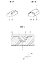
- FIG. 8A is a perspective view of a lower mold
- FIG. 8B is a perspective view showing stringers formed on the lower mold side of FIG. 8A
- FIG. 8C is a cross-sectional view showing stringers formed on the lower mold side.
- FIG. 9A is a diagram showing a modification of the preheating area
- FIG. 9B is a diagram showing another modification of the preheating area.
- FIG. 1A is a perspective view showing an object to be molded w
- FIG. 1B is a schematic perspective view showing the molding apparatus 100 of FIG. 1A
- FIG. is a perspective view showing a body panel).
- a molding apparatus 100 of the present embodiment shown in FIG. 1B molds a thin plate-shaped molding object w as shown in FIG. 1A so as to be curved in the thickness direction of the molding object w as shown in FIG. 1C.
- the object to be molded w is a prepreg laminate in which carbon fibers are impregnated with a thermoplastic resin prepared in advance.
- the above prepreg is an intermediate material in which fibers are impregnated with resin. After laminating this to form a laminate, fiber reinforced plastic (FRP) is manufactured through processes such as consolidation.
- the fiber reinforced plastic molded in this embodiment is a carbon fiber reinforced thermoplastic resin composite (CFRTP).
- the molding apparatus 100 of this embodiment includes an upper mold 1 and a lower mold 2.
- the lower surface of the upper mold 1 is formed in a concave shape
- the upper surface of the lower mold 2 is formed in a convex shape so as to be in close contact with the lower surface of the upper mold 1 .
- the object to be molded w is molded while being conveyed in the feed direction Ds by relative positional displacement between the upper mold 1 and the lower mold 2 .
- the object to be molded w is placed on the lower mold 2 and sent to a predetermined position along the feeding direction Ds. press .
- the object to be molded w is sent to the next predetermined position in the feeding direction Ds by the above-described relative positional displacement, and is pressed by the upper mold 1 at the predetermined position.
- the molding apparatus 100 repeats a cycle of conveying the molding object w and pressing the molding object w.
- the molding object w in which the curved surface shape is continuously formed in the longitudinal direction, as shown in FIG. 1C.
- a method for molding such an object w to be molded will be described in detail.
- the above-described feed direction Ds is used as a reference, and the width direction Dh is the direction perpendicular to the feed direction Ds in which the molding object w placed on the lower mold 2 extends.
- a direction orthogonal to both the feed direction Ds and the width direction Dh is defined as a height direction Dt.
- the above-described relative positional displacement between the upper mold 1 and the lower mold 2 is realized by moving the lower mold 2, but it is also included in the present disclosure that it is realized by moving the upper mold 1.
- the mold for placing the object w to be molded is described as the lower mold 2, and the mold facing it is described as the upper mold 1.
- the direction in which the two face each other does not have to match the direction of gravity as long as it does not deviate from the intent of the present disclosure.
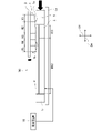
- FIG. 2 is a diagram showing the configuration of the molding apparatus 100 according to this embodiment
- FIG. 3 is a block diagram showing the configuration of the control system in the molding apparatus 100.
- the molding apparatus 100 includes an upper mold support section 3, a conveying device 4, a pressure receiving plate 5, and a control device 10 in addition to the upper mold 1 and the lower mold 2 described above. .
- control device 10 in the present disclosure may be general purpose processors, dedicated processors, integrated circuits, ASICs (Application Specific Integrated Circuits), conventional circuits, and/or those configured or programmed to perform the disclosed functions. can be performed using a circuit containing a combination, or a processing circuit.
- a processor is considered a processing circuit or circuit because it includes transistors and other circuits.
- a circuit, unit, or means is hardware that performs or is programmed to perform the recited functions.
- the hardware may be the hardware disclosed herein, or other known hardware programmed or configured to perform the recited functions.
- a circuit, means or unit is a combination of hardware and software where the hardware is a processor which is considered a type of circuit, the software being used to configure the hardware and/or the processor.
- the lower mold 2 is formed in, for example, a rectangular shape in plan view.
- the lower mold 2 is heated to a predetermined temperature and supports the object w to be molded.
- the melting point Tm of the molding object w is, for example, 305° C., but is not limited to this.
- the lower mold 2 is heated to a temperature lower than the melting point Tm of the molding object w, which is a predetermined temperature T11 in this embodiment.
- the predetermined temperature T11 is, for example, 300° C., but this predetermined temperature is not limited to this, either, and is determined appropriately based on the melting point Tm of the object to be molded w, for example, within the range of Tm ⁇ 10° C. .
- the temperature of the lower mold 2 is detected by a temperature sensor 43b such as a thermocouple or an infrared camera.
- a plurality of heaters 40b are provided in the lower mold 2.
- 12 heaters 40b are provided in the longitudinal direction of the molding object w, that is, the feed direction Ds, but the present invention is not limited to this.
- the number of control channels for the heaters 40b by the controller 10 for the lower die 2 (that is, the number equal to the total number of heaters 40b arranged) is 48.
- the temperature of the lower mold 2 is adjusted by controlling the heating operation of these heaters 40 b by the control device 10 .
- the lower mold 2 has a temperature range R11 (that is, a first lower mold temperature range) controlled to be the above-mentioned predetermined temperature T11 and a temperature range lower than the predetermined temperature T11.
- a temperature region R12 that is, the second lower mold temperature region
- T12 the length of the lower die 2 in the feed direction Ds is, for example, 2500 mm, it is not limited to this.
- the upper mold 1 is supported by the upper mold supporting portion 3.
- the upper mold 1 is configured to be bi-directionally movable in the height direction Dt and is arranged to face the lower mold 2 to press the object w to be molded.
- the upper die 1 has a plurality of temperature regions arranged side by side in the feeding direction Ds and temperature-controlled independently of each other by the control device 10 .
- the control device 10 controls the temperature regions arranged in the feeding direction Ds to have different temperatures.
- the upper mold 1 is provided with five temperature regions R1, R2, R3, R4, and R5. These temperature regions R1 to R5 are arranged in the feeding direction Ds.
- a plurality of heaters 40a are also provided in the upper mold 1, and at least one heater 40a is provided for each temperature region. The heating operation of the upper mold 1 by the heater 40 a is controlled by the controller 10 .
- one heater 40a is provided in each of the temperature regions R1, R3, R4, and R5, and two heaters 40a are provided in the temperature region R2, in the feeding direction Ds of the molding object w. .
- the width direction Dh for example, four heaters 40a are provided for each temperature region.
- heaters 40a are arranged in the feeding direction Ds of the molding object w, and four heaters 40a are arranged in the width direction Dh.
- the number equal to the total number of heaters 40a connected to each other) is 24, but is not limited to this.
- the transport device 4 includes a base portion 4a and a driving portion 4b.
- the lower mold 2 and the pressure receiving plate 5 are provided on the base portion 4a.
- the pressure receiving plates 5 are arranged at both ends of the lower die 2 in the feeding direction Ds and in the width direction Dh. Each pressure receiving plate 5 and the lower die 2 are in contact with each other.
- the driving section 4b of the conveying device 4 conveys the base section 4a supporting the lower mold 2 in the feed direction Ds.
- the driving portion 4b can be, for example, a gear mechanism and includes a rack gear, a pinion gear and an electric motor.
- the rotation of the pinion gear connected to the rotating shaft of the electric motor causes the rack gear provided on the base portion 4a to move in the feeding direction Ds.
- the base portion 4a moves in the feed direction Ds, and the lower die 2 can be moved in the feed direction Ds accordingly.
- the transport device 4 and its driving section 4b can appropriately select the method as long as the functions described above are exhibited and the essence of the present disclosure is not impaired.
- the drive source of the drive unit 4b may be an internal combustion engine.
- the control device 10 performs control so that the temperatures T1 to T5 in the temperature regions R1 to R5 are lowered from the upstream side to the downstream side (from the right side to the left side in FIG. 2) in the feeding direction Ds. Specifically, the temperature T1 of the temperature region R1 is heated to the process temperature Tp (for example, in the range of 350° C. to 400° C.), which is the highest temperature in each region.
- the process temperature Tp is a reference temperature for molding that is determined in consideration of the melting point Tm of the object to be molded w, and its temperature range is not limited to the range described above.
- the temperature region R2 is set to T2, which is lower than the temperature of the temperature region R1 and equal to or higher than the melting point Tm.
- the temperature T2 of the temperature region R2 is set to a temperature at which the viscosity of the molding object w starts to decrease when the molding object w is pressurized by the downstream end of the preheating region 1a, which will be described later. This is to allow pressure to be applied to the
- the temperatures T1 to T5 of the temperature regions R1 to R5 of the upper mold 1 are detected by the temperature sensor 43a in the same manner as the lower mold 2.
- the temperatures T3 to T5 of the temperature regions R3, R4, and R5 of the upper mold 1 are set to satisfy T2>T3>T4>T5 as described above.
- the temperature range of the temperatures T3 to T5 is set to be, for example, 50° C. to 150° C. lower than the process temperature Tp, but is not limited to this.
- the length of the upper mold 1 in the feed direction Ds in this embodiment is, for example, 1080 mm
- the length of the upper mold 2 in the feed direction Ds is not limited to this.
- the lengths of the upper mold 1 and the lower mold 2 in the feeding direction Ds may be changed, for example, by the length of the molding object w in the feeding direction Ds.
- the lengths and the number of temperature regions R1, R2, R3, R4, and R5 of the upper mold 1 in the feed direction Ds also include the lengths of the upper mold 1 itself and the object to be molded w in the feed direction Ds. , and is determined in association with a predetermined amount of movement of the base portion 4a in the feeding direction Ds, which will be described later.
- the upper die 1 has a preheating area 1a arranged upstream in the feeding direction Ds, and a downstream heating area 1b arranged downstream of the preheating area 1a in the feeding direction Ds.
- the preheating region 1a is arranged at a position spanning the temperature regions R1 and R2
- the downstream heating region 1b is arranged at a position spanning the temperature regions R3, R4, and R5.
- Such a preheating area 1a is spaced apart from the molding object w when the downstream heating area 1b is in contact with the molding object w. That is, the thickness in the height direction Dt of the preheating region 1a is smaller than the thickness in the height direction Dt of the downstream heating region 1b.
- the temperature regions R1 and R2 of the upper mold 1 do not touch the molding object w, whereas the temperature regions R3 to R5 intermittently touch the molding object w. Contact and separation with the molding object w are repeated.
- the preheating region 1a in order to realize the above-described spaced apart arrangement of the preheating region 1a with respect to the object w to be molded, the preheating region 1a has one or more of a horizontal surface, an inclined surface, and a curved surface on the side of the object w to be molded. have a face.
- FIG. 2 shows an example in which the surface of the preheating area 1a on the molding object w side is an inclined surface.
- each of the temperature regions R1 to R5 has been described above, but the minimum necessary in the present disclosure
- the temperature of the entire preheating region 1a is higher than the melting point of the molding object w
- the temperature of the downstream heating region 1b is lower than the melting point of the molding object w
- the temperature of the lower mold 2 is It is preferable that each temperature be set so that the temperature is lower than the melting point of the molding object w and equal to or higher than the temperature of the downstream heating region 1b.
- it is effective in promoting resin crystallization in the consolidation of the molding object w. has been found from experiments, and the configuration described above is adopted.
- FIG. 4A is a diagram for explaining the first preheating step of the molding object w
- FIG. 4B is a diagram for explaining the first consolidation step
- 5A and 5B are diagrams for explaining the second and subsequent consolidation steps, the transfer of the molding object w, and the changing step of the temperature region ratio of the lower mold 2.
- the steps shown in FIG. 4A are as follows. First, the downstream end portion (the left end portion in the drawing) of the flat plate-shaped molding object w is first preheated (that is, heated before pressurization). In this case, the preheating region 1a (portion corresponding to the temperature regions R1 and R2) of the upper mold 1 is arranged at a distance from the downstream end of the molding object w. to heat. As a result, the temperature of the downstream end of the object to be molded w rises. A single temperature region R11 is formed in the lower mold 2 at this time.
- the base portion 4a is moved by a predetermined amount in the feeding direction Ds.
- the amount of movement is, for example, 1/10 of the length of the object to be molded w in the feeding direction Ds.
- the object to be molded w moves in the feeding direction Ds by a predetermined amount.
- the downstream end of the molding object w is pressurized.
- the downstream end of the molding object w is pressurized (consolidated) by the temperature region R3 of the upper mold 1 and the temperature region R11 of the lower mold 2 .
- the pressurization time is, for example, 10 seconds or more, but is not limited to this.
- a portion (eg, central portion) upstream of the downstream end of the molding object w is positioned so as to overlap the preheating area 1a when viewed from the height direction Dt of the preheating area 1a. Therefore, preheating is performed at the same time in this process for the part on the upstream side of the downstream end of the object to be molded w.
- the object to be molded w and the preheating region 1a are not in contact with each other. Therefore, preheating is performed by heat radiation from the preheating area 1a or by convection of the air warmed by the preheating area 1a.
- the steps shown in FIG. 5A are as follows. While the upper die 1 is raised, the base portion 4a is moved by a predetermined amount in the feeding direction Ds. Along with this, the object to be molded w moves in the feeding direction Ds by a predetermined amount.
- the lower die 2 is controlled by means described later so as to change from a state having a single temperature region R11 to a state having both temperature regions R11 and R12 arranged side by side in the feed direction Ds.
- the temperature region R12 is formed downstream of the temperature region R11.
- the boundary line between the temperature regions R11 and R12 is set at a position overlapping the temperature region R3 of the upper mold when viewed from above in the height direction Ds.
- downstream end of the molding object w has moved to a position overlapping the temperature region R4 or the temperature region R5 of the upper mold when viewed from the upper side in the height direction Ds (in the present embodiment, the temperature region R5 overlapping positions).
- pressure is applied to the downstream end of the object to be molded w and a portion upstream of the downstream end.
- the downstream end of the molding object w is cooled by the temperature regions R4 and R5 in the upper mold 1 and the temperature region R12 in the lower mold 2, and the temperature in the temperature region R3 in the upper mold 1 and the temperature in the lower mold 2
- the region R11 pressurizes (consolidates) the portion upstream of the downstream end of the object to be molded w.
- the portion is preheated since the central portion of the molding object w is located below the preheating region 1a, the portion is preheated.
- the downstream temperature region 1b of the upper mold 1 includes a consolidation heating region (that is, the temperature region R3) for consolidating the molding object w and a cooling region (that is, the temperature region R4 and R5).
- a pipe (not shown) is provided in the lower die 2 for circulating the cooling medium.
- a cooling medium such as air or water is circulated through the piping by the pump 41 (FIG. 3), whereby the lower die 2 can be cooled by water cooling.
- a cooling means for the lower die 2 an air-cooling system using a fan 42 (FIG. 3) may be employed, or the above-described water-cooling system and air-cooling system may be used together.
- the ratio between the temperature region R12 and the temperature region R11 of the lower mold 2 is changed by the control device 10. Specifically, since the temperature regions R4 and R5 of the upper mold 1 move in the feed direction Ds as the molding object w is conveyed, the boundary line between the temperature regions R11 and R12 is In the embodiment, it is set at a position overlapping the temperature region R3 of the upper die when viewed from above in the height direction Ds. As a result, in the second and subsequent consolidation steps, when the temperature regions R4 and R5 of the upper mold come into contact with the object w to be molded, the temperature regions R4 and R5 are always lowered when viewed from above in the height direction Ds. It is arranged at a position overlapping the temperature region R12 of the mold.
- each step of conveying, consolidating, and cooling the object w to be molded is performed only by the upper mold 1 and the lower mold 2 without providing a dedicated structure for conveying the object to be molded w. can be carried out, and therefore molding of thermoplastic resin products can be performed in a highly time-efficient manner.
- the temperature T12 of the temperature region R12 of the lower mold 2 is set to satisfy T11>T12 as described above.
- the temperature T12 is set to a temperature lower than the melting point Tm of the molding object w by 50° C. to 150° C., but is not limited to this.
- the state shown in FIG. 6 is reached through the movement of the base portion 4a in the feeding direction Ds, the change in the ratio of the temperature regions R11 and R12 of the lower mold 2, and the descent of the upper mold 1. Also in the state of FIG. 6, the two steps described with reference to FIG. 5B are performed, and these two steps are repeated thereafter. As a result, the positions of the object to be molded w to be consolidated by the upper mold 1 and the lower mold 2 are changed stepwise from the downstream side to the upstream side. When the cooling pressure in the second and subsequent consolidation steps reaches the upstream end of the object w, the entire molding process of the object w in the molding apparatus 100 of this embodiment is completed.
- the upper mold 1 and the lower mold 2 perform one-time molding of the object w to be molded.
- the preheating, consolidation, and cooling processes can be performed simultaneously, and can be performed continuously in the feed direction Ds for the molding object w.
- FIG. 7 is a flow chart showing the flow of the molding process by the molding apparatus 100 of this embodiment.
- step S0-1 the object to be molded w is supported by the lower mold 2 (step S0-1). Then, the temperature regions R1 to R5 are formed in the upper mold 1 and the temperature region R11 is formed in the lower mold 2 by the control device 10 (step S0-2). After the preparatory step, the main step below is carried out.
- the molding object w is first preheated (step S1).
- the object to be molded w is moved by a predetermined amount in the feeding direction Ds (step S2).
- a first consolidation step is performed (step S3).
- the portion of the molding object w preheated in step S1 is subjected to consolidation (pressurization) and the feeding direction Ds as viewed from the consolidation portion. Preheating of the upstream portion is performed simultaneously.
- step S4 the ratio of temperature range R12 to temperature range R11 is 0, but temperature range R12 is formed when step S4 is performed for the first time. As will be described later, step S4 is repeated several times, but the ratio of temperature range R12 to temperature range R11 increases as step S4 is performed.
- step S5 the second and subsequent consolidation steps are carried out.
- step S5 as described above, the portion of the molding object w consolidated in step S4 is cooled and the portion of the molding object w preheated in step S4 is subjected to consolidation ( Pressurization) and preheating of the portion on the upstream side in the feed direction Ds as seen from the portion being consolidated are all performed at the same time.
- step S6 if there is a portion to be pressurized on the object w to be molded (NO in step S6), the process returns to step S4. On the other hand, if there is no portion to be pressurized on the object to be molded w (YES in step S6), the molding process is terminated.
- the lower mold 2 supporting the molding object w is relatively conveyed with respect to the upper mold 1 in the feeding direction Ds by the conveying device 4 .
- a first temperature region R11 and a second temperature region R12 whose temperature is controlled are formed side by side in the feeding direction Ds in the lower die 2 .
- the ratio of R12 to the temperature region R11 of the lower mold 2 in the feed direction Ds changes according to the relative position between the upper mold 1 and the lower mold 2 . That is, as the lower mold 2 is fed forward, the temperature region R11 becomes smaller and the temperature region R12 becomes larger.
- a dedicated configuration for transportation can be omitted. can.
- the pressurized portion is sequentially cooled. As a result, it is possible to shorten the production time and reduce the cost of the apparatus.
- a plurality of temperature regions are provided side by side in the feeding direction Ds, and are sequentially from the upstream side to the downstream side, the preheating region 1a, and the temperature from the preheating region 1a.
- a downstream heating region 1b having a lower temperature is also formed.
- the preheating region 1a enables preheating of the object w to be molded before pressure molding, and the downstream heating region 1b enables consolidation of the object w to be molded.
- preheating of the object w to be molded and consolidation to pressurize the object w to be molded at a temperature lower than that of the preheating are performed in one pressurizing step performed by the upper mold 1 and the lower mold 2. , can be simultaneously applied to different parts of the object to be molded w.
- the downstream heating region 1b a plurality of temperature regions provided side by side in the feed direction Ds, which are temperature regions R3, which are consolidation temperature regions, in order from the upstream side to the downstream side. , cooling regions R4 and R5 having a lower temperature than the temperature region R3.
- the cooling process for further lowering the temperature can be performed simultaneously with the above-described pressurizing process, and the production time can be further shortened.
- the preheating region 1a of the upper mold 1 is set to a temperature equal to or higher than the melting point Tm of the molding object w
- the downstream heating region 1b is set to a temperature lower than the melting point of the molding object w.
- the control device 10 controls the control device 10 so that By changing the temperature to be applied according to the parameters of the object to be molded w, one molding apparatus 100 can handle a plurality of types of molded products.
- the temperature setting of the temperature region of the lower mold 2 is also controlled by the control device 10 so that it is equal to or higher than the temperature of the surface of the downstream heating region of the upper mold 1 and lower than the melting point Tm of the molding object w. be.
- the preheating region 1a and the molding object w are separated from each other when the upper mold 1 and the lower mold 2 apply pressure to the molding object w.
- the preheating part 1a has a smaller thickness than the downstream heating part 1b so that when the downstream heating part 1b is pressed against the molding object w, the preheating part 1a is separated from the molding object w.
- the temperature range of the downstream heating section 1b is set to a temperature higher than that of the preheating section 1a.
- the thickest region of the upper mold 1 is set to a temperature lower than the other thinner temperature regions of the upper mold 1 .
- the upper die 1 in the present invention adopts the above-described shape for the purpose of carrying out preheating in a non-contact manner.
- a molding apparatus 100 can mold an object to be molded w having a stringer 21 with a hat-shaped cross section on the surface to be molded by the lower mold 2a.
- the stringer 21 is installed in the recess 22 provided in advance in the lower mold 2 a , and then the core 20 is inserted into the recess of the stringer 21 .
- the object to be molded w is placed along the surfaces of the lower mold 2a and the core 20, and molding is performed in the same manner as in the above embodiment.
- the temperature of the lower mold 2a is set to a temperature lower than the melting point of the stringer 21 and equal to or higher than the temperature of the downstream heating region 1b.
- the object w to be molded and the stringer 21 are integrally molded. Note that the core 20 is removed after integral molding.
- the stringer 21 is formed on the lower mold 2a side of the object to be molded w, but the present disclosure also includes a configuration in which the stringer is formed on the upper mold 1 side. In this case, the recess 22 is provided in the upper mold 1 .
- an upper die 30 may be employed which has a preheating area 1a1 partially or entirely formed of a horizontal surface and partitioned from the downstream heating area 1b by a step.
- an upper die 31 having a preheating region 1a2 including a curved surface may be employed.
- the connecting portion between the downstream heating region 1b and the preheating region 1a is preferably changed continuously to some extent.
- the lower mold 2 is moved in the feeding direction Ds by the conveying device 4 in order to relatively convey the lower mold 2 and the upper mold 1 in the feeding direction Ds.
- the upper mold 1 may be moved in the feeding direction Ds, or both the upper mold 1 and the lower mold 2 may be moved.
- the upper mold 1 moves in the height direction Dt when consolidation is performed. 2 may move.
- the relative movement in each direction between the upper mold 1 and the lower mold 2 in the present disclosure can be realized by any means or method.
- the upper die 1 and the lower die 2 do not move relative to each other in the width direction Dh. 1 and the lower mold 2 may be configured.
- the stringers and the upper mold 1 or the lower mold 2 In order to avoid contact with the upper mold 1 and the lower mold 2, the relative movement may be performed simultaneously in the height direction Dt and the width direction Dh.
- the present disclosure can be suitably applied to the manufacture of parts for relatively large equipment such as aircraft, but can also be applied to the manufacture of thermosetting resin parts for various other articles.
- the object to be molded in the present embodiment is a carbon fiber reinforced thermoplastic resin molded product, it can be used for molding a thermoplastic resin molded product reinforced with glass fiber, for example, and can be fiber reinforced. It can also be used to mold thermoplastic resin parts that do not require
Abstract
成形装置は、熱可塑性樹脂を含む被成形対象物を支持し、所定温度に加熱された下型と、下型に対向して配置され、被成形対象物を加圧するとともに所定温度に加熱された上型と、下型と上型とを送り方向に相対的に搬送させる搬送装置と、制御装置と、を備え、下型は、送り方向に並んで設けられる複数の温度領域であって、第1の下型温度領域と、第1の下型温度領域よりも温度の低い第2の下型温度領域とを含み、制御装置は、上型と下型との相対位置に応じて、下型における第1の下型温度領域と第2の下型温度領域の比率を変化させる。
Description
本開示は、熱可塑性複合材を用いた被成形対象物の成形装置および成形方法に関する。
従来、航空機の胴体パネル(スキンパネル)は、成形性、組立性の観点から、周方向および長手方向に分割された数mオーダの長尺パネルを組み合わせて製造されている。近年ではスキンパネルの材質として熱可塑性複合材(CFRTP)が採用されている。熱可塑性複合材よりなる長尺パネルを成形する方法として、例えば特許文献1に開示されているオートクレーブ法や、その他には特許文献2および3に開示されるプレス法がある。
しかしながら、オートクレーブ法による熱可塑性複合材成型では高温(例えば400℃)でのコンソリデーション(加熱・加圧成型)が必要なため、適用可能な副資材が少なく、またコンソリデーションに要する時間が長く、それゆえ生産時間の短縮化を図ることが困難であった。また、オートクレーブ法では、エネルギーコストが高くなるという課題もあった。
一方、プレス法では、一般的には長尺パネルの成形はプレス寸法の制約上困難であった(例えば特許文献2)。なお、熱可塑性複合材の連続成形法として知られている、CCM(Continuous Compression Molding)技術であっても、大型のパネルや断面形状が変化するパネルをプレスすることは困難であった。
特許文献3ではプレス法における本課題の解決のため、長尺のプレス型にプリプレグ積層体を設置し、コンソリデーションと型の長手方向移動を繰り返すことによって長尺パネルの成型を実現している。しかし、この方法ではコンソリデーション後のパネルの冷却工程を大気開放による自然冷却としており、パネル全体のコンソリデーションと部品冷却が別工程として切り分けられているため、成型完了に時間がかかるという問題があった。
そこで、本開示は、熱可塑性複合材成型における生産時間の短縮化を図ると共に、大型の被成形対象物や断面形状が変化する被成形対象物の成形を良好に行うことができる熱可塑性複合材の成形装置および成形方法を提供することを目的とする。
本開示の成形装置は、熱可塑性樹脂を含む被成形対象物を支持し、所定温度に加熱された下型と、前記下型に対向して配置され、前記被成形対象物を加圧するとともに所定温度に加熱された上型と、前記下型と前記上型とを送り方向に相対的に搬送させる搬送装置と、制御装置と、を備え、前記下型は、前記送り方向に並んで設けられる複数の温度領域であって、第1の下型温度領域と、前記第1の下型温度領域よりも温度の低い第2の下型温度領域とを含み、前記制御装置は、前記上型と前記下型との相対位置に応じて、前記下型における前記第1の下型温度領域と前記第2の下型温度領域の比率を変化させるものである。
本開示に従えば、搬送装置によって被成形対象物を支持する下型が上型に対して送り方向に相対的に搬送される。これにより、被成形対象物における送り方向の各部位に対する加圧を当該送り方向に順に行うことができる。これによって、大型の被成形対象物や断面形状が変化する被成形対象物の成形を送り方向に分けて良好に行うことができる。また、温度制御された第1、第2の温度領域が下型において送り方向に並んで形成され、この比率が上型と下型の相対位置に応じて変化するので、加工工程の進行中に下型から被成形対象物を取り下ろすことなく、被成形対象物の予備加熱、コンソリデーションおよび冷却の各プロセスを同時に被成形対象物の異なる部位にそれぞれ付与することが可能となる。これによって、生産時間の短縮化を図ることができる。また、オートクレーブに要されるエネルギーコストもなくすことができ、経済的である。
本開示によれば、熱可塑性複合材成型における生産時間の短縮化を図ると共に、大型の被成形対象物や断面形状が変化する被成形対象物の成形を良好に行うことができる熱可塑性複合材の成形装置および成形方法を提供することができる。
以下、本開示の一実施形態に係る成形装置および成形方法について、図面を参照しながら説明する。以下に説明する成形装置および成形方法は、本開示の一実施形態に過ぎない。従って、本開示は以下の実施形態に限定されるものではなく、本開示の趣旨を逸脱しない範囲で追加、削除および変更が可能である。
図1Aは被成形対象物wを示す斜視図であり、図1Bは図1Aの成形装置100を示す概略斜視図であり、図1Cは成形後の被成形対象物wであるスキンパネル(航空機の胴体パネル)を示す斜視図である。
図1Bに示す本実施形態の成形装置100は、図1Aに示すような薄板状の被成形対象物wを、図1Cに示すように被成形対象物wの厚み方向に湾曲させるように成形するためのものである。本実施形態において、被成形対象物wは、事前に準備された熱可塑性樹脂を炭素繊維に含侵させたプリプレグ積層体である。
上記のプリプレグとは、繊維に樹脂を含侵させた中間材料であり、これを積層して積層体とした後、コンソリデーション等の工程を経て繊維強化プラスチック(FRP)を製造する。本実施例にて成型する繊維強化プラスチックは炭素繊維強化熱可塑性樹脂複合材(CFRTP)である。
図1Bに示すように、本実施形態の成形装置100は上型1および下型2を備えている。上型1の下面は凹状に形成されており、下型2の上面は上型1の下面に密着するように凸状に形成されている。後で詳述するが、被成形対象物wは上型1と下型2との相対位置変位により、送り方向Dsに搬送されつつ成形されるようになっている。詳細には、被成形対象物wは下型2上に配置された状態で送り方向Dsに沿って所定位置まで送られ、当該所定位置において上型1が下方に移動して被成形対象物wを押圧する。その後、上型1が上昇されると、被成形対象物wは前述の相対位置変位によって送り方向Dsに次の所定位置まで送られ、当該所定位置で上型1に押圧される。このように、成形装置100によって、被成形対象物wの搬送および当該被成形対象物wに対する押圧からなるサイクルが繰り返される。これにより、図1Cに示すような、曲面形状が長手方向に連続して形成された被成形対象物wを得ることができる。以下、このような被成形対象物wの成形方法について詳しく説明する。なお、以降のすべての説明および図において、前述の送り方向Dsを基準とし、送り方向Dsに直交し、下型2上に配置された被成形対象物wが延在する方向を幅方向Dhと定義し、送り方向Dsとも幅方向Dhとも直交する方向を高さ方向Dtと定義する。
本実施形態では、前述の上型1と下型2の相対位置変位を、下型2が移動することによって実現するが、上型1が移動することによって実現することも本開示に含まれる。また、前述の通り、本実施形態では被成形対象物wを配置する型を下型2、これに対向する型を上型1と記載しているが、上下の表現は便宜上のものであり、両者が対抗する方向は本開示の意図を逸脱しない範囲であれば特に重力方向と一致していなくてもよい。
図2は本実施形態に係る成形装置100の構成を示す図であり、図3は成形装置100における制御系統の構成を示すブロック図である。図2に示すように、成形装置100は、前述した上型1および下型2の他に、上型支持部3と、搬送装置4と、受圧板5と、制御装置10とを備えている。
なお、本開示における制御装置10は、開示された機能を実行するよう構成またはプログラムされた汎用プロセッサ、専用プロセッサ、集積回路、ASIC(Application Specific Integrated Circuits)、従来の回路、および/または、それらの組み合わせ、を含む回路または処理回路を使用して実行できる。プロセッサは、トランジスタやその他の回路を含むため、処理回路または回路と見なされる。本開示において、回路、ユニット、または手段は、列挙された機能を実行するハードウエアであるか、または、列挙された機能を実行するようにプログラムされたハードウエアである。ハードウエアは、本明細書に開示されているハードウエアであってもよいし、あるいは、列挙された機能を実行するようにプログラムまたは構成されているその他の既知のハードウエアであってもよい。ハードウエアが回路の一種と考えられるプロセッサである場合、回路、手段、またはユニットはハードウエアとソフトウエアの組み合わせであり、ソフトウエアはハードウエアおよび/またはプロセッサの構成に使用される。
下型2は平面視で例えば矩形状に形成されている。下型2は、所定温度に加熱され、被成形対象物wを支持する。本実施形態において、被成形対象物wの融点Tmは例えば305℃であるが、これに限定されない。下型2は被成形対象物wの融点Tmよりも低い温度、本実施例の場合だと所定温度T11に加熱される。所定温度T11は、例えば300℃であるが、この所定温度についてもこれに限定されず、被成形対象物wの融点Tmをもとに適切な温度、例えばTm±10℃の範囲で決定される。下型2の温度は、例えば熱電対や赤外線カメラ等の温度センサ43bにより検出される。なお、下型2内には複数のヒータ40bが設けられており、当該ヒータ40bは被成形対象物wの長手方向すなわち送り方向Dsにおいて、例えば12個設けられるが、これに限定されない。
また、送り方向Dsに直交する幅方向Dhにおいては、例えば4つのヒータ40bが設けられる。以上により、下型2について制御装置10によるヒータ40bの制御チャンネル数(すなわち配置されるヒータ40bの総数と等しい数)は48となっている。これらのヒータ40bによる加熱動作が制御装置10により制御されることによって、下型2の温度が調整されている。後述するが、被成形対象物wの成形工程中、この構成によって下型2は前述の所定温度T11となるよう制御された温度領域R11(すなわち第1下型温度領域)と、所定温度T11よりも低い温度T12になるように調整された温度領域R12(すなわち第2下型温度領域)の2つの温度領域を持つように制御される。なお、下型2の送り方向Dsにおける長さは例えば2500mmであるが、これに限定されない。
上型1は上型支持部3に支持されている。上型1は、高さ方向Dtに双方向動可能に構成されると共に下型2に対向して配置され、被成形対象物wを加圧する。上型1は、送り方向Dsに並んで設けられて制御装置10により互いに独立して温度制御される複数の温度領域を有している。制御装置10は被成形対象物wを成形する際に、送り方向Dsに並ぶ上記温度領域を互いに異なる温度に制御する。
具体的には、図2に示すように、上型1には5つの温度領域R1,R2,R3,R4,R5が設けられている。これらの温度領域R1~R5は送り方向Dsにそれぞれ並んでいる。なお、上型1内にも複数のヒータ40aが設けられており、当該ヒータ40aは各温度領域について少なくとも1つ設けられる。ヒータ40aによる上型1の加熱動作は制御装置10によって制御される。本実施形態では、被成形対象物wの送り方向Dsにおいて、温度領域R1,R3,R4,R5には例えばそれぞれ1つのヒータ40aが設けられ、温度領域R2には例えば2つのヒータ40aが設けられる。また、幅方向Dhにおいては、各温度領域について例えばそれぞれ4つのヒータ40aが設けられる。以上によって、ヒータ40aは被成形対象物wの送り方向Dsに6つ配置され、幅方向Dhに4つ配置されるので、上型1について制御装置10によるヒータ40aの制御チャンネル数(すなわち配置されるヒータ40aの総数と等しい数)は24となっているが、これに限定されない。
搬送装置4はベース部4aおよび駆動部4bを備えている。下型2および受圧板5はベース部4a上に設けられている。受圧板5は下型2の送り方向Dsにおける両端および幅方向Dhにおける両端に配置されている。各受圧板5と下型2とは接触している。
搬送装置4の駆動部4bは、制御装置10による制御の下、下型2を支持するベース部4aを送り方向Dsに搬送する。駆動部4bは、例えばギア機構とすることができ、ラックギア、ピニオンギアおよび電動モータを含む。この場合、電動モータの回転軸に接続されたピニオンギアの回転によって、ベース部4aに設けられたラックギアを送り方向Dsに移動させる。これにより、ベース部4aが送り方向Dsに移動し、これに伴って下型2を送り方向Dsに移動させることができる。なお、搬送装置4とその駆動部4bは、以上に述べた機能を発揮し、かつ本開示の本質を損なわない限りにおいて、適宜その方式を選択できる。例えば、駆動部4bの駆動源を内燃機関としてもよい。
制御装置10は、温度領域R1~R5の各々の温度T1~T5が送り方向Dsの上流側から下流側(図2では右側から左側)にかけて低くなるように制御を行う。具体的には、温度領域R1の温度T1は、各領域の中で最も高い温度であるプロセス温度Tp(例えば350℃~400℃の範囲)に加熱される。プロセス温度Tpは、被成形対象物wの融点Tmを考慮して決定される、成型する際の基準となる温度であり、その温度範囲は前述の範囲に限定されない。
次に、温度領域R2は、温度領域R1の温度よりも低く、且つ融点Tmと同等か、これより高い温度であるT2に設定される。このように温度領域R2の温度T2を設定するのは、後述する予備加熱領域1aの下流端により被成形対象物wを加圧する際に、当該被成形対象物wの粘度が低下し始める温度にて加圧できるようにするためである。なお、上型1の温度領域R1~R5の各々の温度T1~T5は、下型2と同様に温度センサ43aにより検出される。
また、上型1の温度領域R3,R4,R5の温度T3~T5は、前述の通りT2>T3>T4>T5となるようにそれぞれ設定される。また温度T3~T5の温度範囲は、例えばプロセス温度Tpから50℃~150℃低い温度となるよう設定されるが、これに限定されない。なお、本実施例における上型1の送り方向Dsにおける長さは例えば1080mmだが、上型2の送り方向Dsにおける長さはこれに限定されない。上型1および下型2の送り方向Dsにおける長さは、例えば被成形対象物wの送り方向Dsにおける長さによって変更されてよい。また上型1の温度領域R1,R2,R3,R4,R5の送り方向Dsにおける各々の長さや領域の個数についても、上型1自体と被成形対象物wの送り方向Dsにおける長さをもとに、後述するベース部4aの送り方向Dsへの所定の移動量と関連付けて決定される。
ここで、上型1は、送り方向Dsの上流側に配置された予備加熱領域1aと、当該予備加熱領域1aの送り方向Dsの下流側に配置された下流側加熱領域1bとを有している。本実施形態では、予備加熱領域1aは前述した温度領域R1,R2に亘る位置に配置され、下流側加熱領域1bは温度領域R3,R4,R5に亘る位置に配置される。
このような予備加熱領域1aは、下流側加熱領域1bが被成形対象物wに接触した状態のときに、当該被成形対象物wに対して離間配置される。すなわち、予備加熱領域1aの高さ方向Dtにおける厚みは、下流側加熱領域1bの高さ方向Dtにおける厚みよりも小さくなっている。言い換えると、本実施形態における被成形対象物wの成型工程において、上型1の温度領域R1とR2は被成形対象物wに触れることがなく、対して温度領域R3~R5は断続的に被成形対象物wとの接触と離間とを繰り返す。また本実施形態では、予備加熱領域1aの被成形対象物wに対する上記離間配置を実現すべく、予備加熱領域1aは被成形対象物wの側に水平面、傾斜面および曲面のうち1つ以上の面を有している。図2は予備加熱領域1aの、被成形対象物wの側の面が傾斜面である例を示している。
温度領域R1~R5の各々の送り方向Dsにおける長さおよび温度T1~T5、下型の温度領域R11,R12、R11の温度T11、ならびにR12の温度T12について前述したが、本開示における必要最低限の構成として、予備加熱領域1a全体の温度が被成形対象物wの融点以上の温度となり、下流側加熱領域1bの温度が被成形対象物wの融点未満の温度となり、下型2の温度が被成形対象物wの融点未満で且つ下流側加熱領域1bの温度以上の温度となるように、各々設定されることが好ましい。本実施形態においては、予備加熱領域1aと下流側加熱領域1bの中でさらに段階的な温度領域を設定することで、被成形対象物wのコンソリデーションにおける樹脂結晶化の促進に効果があることが実験から判明しており、前述の構成とした。
続いて、本実施形態の成形装置100による成形方法について、図面を参照しながら工程ごとに説明する。図4Aは被成形対象物wの最初の予備加熱工程を説明するための図であり、図4Bは第1のコンソリデーション工程を説明するための図である。また、図5Aおよび図5Bは第2以降のコンソリデーション工程と、被成形対象物wの搬送および下型2の温度領域比率の変化工程を説明するための図である。なお、図4および図5における送り方向Dsの上流側と下流側は、図2と同じく上流が右側、下流が左側となる。
図4Aに示す工程は次の通りである。最初に、平板状の被成形対象物wの下流端部(同図では左端部)に対して最初の予備加熱(つまり、加圧前の加熱)を行う。この場合、上型1の予備加熱領域1a(温度領域R1,R2に対応する部位)が被成形対象物wの下流端部に対して離間配置された状態で被成形対象物wの下流端部を加熱する。これにより、被成形対象物wの下流端部の温度が上昇する。なお、この時の下型2には単一の温度領域R11が形成されている。
次に、図4Bに示す工程は次の通りである。ベース部4aを送り方向Dsに所定量移動させる。移動量は、例えば被成形対象物wの送り方向Dsにおける長さの10分の1である。これに伴って、被成形対象物wが送り方向Dsに所定量移動する。その後、上型1を下降させることで、被成形対象物wの下流端部が加圧される。詳しくは、上型1における温度領域R3の部位と下型2における温度領域R11によって、被成形対象物wの下流端部が加圧(コンソリデーション)される。加圧時間は例えば10秒以上であるが、これに限定されない。このとき、被成形対象物wの下流端部よりも上流側の部位(例えば中央部分)は予備加熱領域1aの高さ方向Dtから見たとき、予備過熱領域1aに重なるように位置する。そのため、被成形対象物wの下流端部よりも上流側の部位に対しては、この工程で同時に予備加熱が行われる。なおこのとき、前述の上型1の形状から、被成形対象物wと予備加熱領域1aとは接触していない。このため、予備加熱は、予備加熱領域1aによる熱放射、あるいは予備加熱領域1aによって暖められた空気の対流によって行われる。
続いて、図5Aに示す工程は次の通りである。上型1を上昇させると共に、ベース部4aを送り方向Dsに所定量移動させる。これに伴って、被成形対象物wが送り方向Dsに所定量移動する。この際、下型2は、後述する手段で、単一の温度領域R11を持つ状態から、送り方向Dsに並んで配置される温度領域R11およびR12を併せ持つ状態に変化するよう制御される。温度領域R12は温度領域R11の下流側に形成される。温度領域R11と温度領域R12との境界線は、本実施形態においては高さ方向Dsの上側から見て上型の温度領域R3と重なる位置に設定される。また、被成形対象物wの下流端部は、高さ方向Dsの上側から見て上型の温度領域R4または温度領域R5と重なる位置まで移動している(本実施形態においては温度領域R5と重なる位置としている)。この状態で、図5Bに示すように、上型1を下降させることで、被成形対象物wの下流端部および下流端部よりも上流側の部位が加圧される。詳しくは、上型1における温度領域R4,R5の部位と下型2における温度領域R12によって、被成形対象物wの下流端部が冷却され、上型1における温度領域R3と下型2における温度領域R11によって、被成形対象物wの下流端部よりも上流側の部位が加圧(コンソリデーション)される。このとき、被成形対象物wの中央部分は予備加熱領域1aの下方に位置するため、当該部分に対しては予備加熱が行われる。
このように、第2以降のコンソリデーション工程では、上型1における温度領域R4,R5の部位による被成形対象物wの前コンソリデーション工程におけるコンソリデーション部分の冷却、温度領域R3の部位による当該コンソリデーション工程におけるコンソリデーション、および温度領域R1、R2の部位による次コンソリデーション工程におけるコンソリデーション部分の予備加熱が同時に実施される。言い換えると、上型1の下流側温度領域1bは、被成形対象物wにコンソリデーションを行うためのコンソリデーション加熱領域(すなわち温度領域R3)と、冷却を行うための冷却領域(すなわち温度領域R4およびR5)とを有する。
下型2には冷却媒体を通流させる図略の配管が設けられている。冷却媒体として例えばエアーや水等を制御装置10による制御の下、ポンプ41(図3)により配管に通流させることで水冷式により下型2を冷却することができる。或いは、下型2の冷却手段として、ファン42(図3)による空冷式を採用してもよいし、上記の水冷式と空冷式を併用して冷却してもよい。前述の通り、図5Aの工程において上型1の温度領域R4,R5によって被成形対象物wの一部が冷却されるときには、下型2にも冷却媒体によって温度が調整された温度領域R12が形成されている。
また、この下型2の温度領域R12と温度領域R11との比率は制御装置10によって変化する。具体的には、被成形対象物wの搬送に伴い、上型1の温度領域R4、R5が送り方向Dsに移動していくことから、温度領域R11と温度領域R12との境界線は、本実施形態においては高さ方向Dsの上側から見て上型の温度領域R3と重なる位置に設定される。これにより、第2以降のコンソリデーション工程において、上型の温度領域R4、R5が被成形対象物wに接触する際には、温度領域R4、R5は高さ方向Dsの上側から見て必ず下型の温度領域R12と重なる位置に配置される。この構成によって、本実施形態では、被成形対象物wの搬送のための専用構造を設けることなく、上型1と下型2のみで被成形対象物wの搬送、コンソリデーションおよび冷却の各工程を実施することができ、それゆえ熱可塑性樹脂製品の成型を高い時間効率で行うことができる。なお、下型2の温度領域R12の温度T12は、前述の通りT11>T12となるように設定される。また温度T12は、例えば被成形対象物wの融点Tmから50℃~150℃ほど低い温度に設定されるが、これに限定されない。
前述の図5Bの状態から、ベース部4aの送り方向Dsの移動と下型2の温度領域R11、R12の比率の変化と上型1の下降とを経て図6に示す状態となる。図6の状態においても、図5Bで説明した二つの工程が実施され、以降この二つの工程が繰り返される。これにより、被成形対象物wは下流側から上流側に向けて、段階的に上型1と下型2によるコンソリデーションが施される位置が変えられていく。第2以降のコンソリデーション工程における冷却加圧が被成形対象物wの上流端部まで達したとき、本実施形態の成形装置100における被成形対象物wの全成型工程が完了する。
以上の通り、本実施形態の成形装置100によれば、被成形対象物wの送り方向Dsにおける各部位に対して、上型1と下型2とで行う被成形対象物wへの一度の加圧工程の中で、予備加熱、コンソリデーションおよび冷却の各工程を同時に実施でき、且つ、被成形対象物wに対して送り方向Dsに連続して実施することができる。
続いて、図7は本実施形態の成形装置100による成形工程の流れを示すフローチャートである。
図7に示すように、準備工程として、被成形対象物wを下型2に支持させる(ステップS0-1)。そして、制御装置10によって上型1に温度領域R1~R5を形成し、下型2に温度領域R11をする(ステップS0-2)。準備工程の後、以下の本工程を実施する。
まず、被成形対象物wに対して最初の予備加熱を実施する(ステップS1)。次に、被成形対象物wを送り方向Dsに所定量移動させる(ステップS2)。次に、第一のコンソリデーション工程を実施する(ステップS3)。第一のコンソリデーション工程では、前述の通り、ステップS1で予備加熱された被成形対象物wの部分に対してのコンソリデーション(加圧)と、コンソリデーションされている部分から見て送り方向Ds上流側の部分への予備加熱とが同時に行われる。
次に、被成形対象物wの搬送、並びに下型の温度領域R11、R12の送り方向Dsにかかる比率変更が行われる(ステップS4)。ステップS4が実施される前は、温度領域R11に対する温度領域R12の比率は0であるが、初めてステップS4が実施される際に温度領域R12が形成される。後述の通りステップS4は幾度か繰り返されるが、以降ステップS4を経るにつれて温度領域R11に対する温度領域R12の比率は大きくなる。
次に、第二以降のコンソリデーション工程を実施する(ステップS5)。ステップS5では、前述の通り、ステップS4でコンソリデーションされた被成形対象物wの部分に対しての冷却と、ステップS4で予備加熱された被成形対象物wの部分に対してのコンソリデーション(加圧)と、コンソリデーションされている部分から見て送り方向Ds上流側の部分への予備加熱とが全て同時に行われる。その後、被成形対象物wについて加圧すべき部位がある場合には(ステップS6でNO)、ステップS4の処理に戻る。一方、被成形対象物wについて加圧すべき部位がない場合には(ステップS6でYES)、成形工程が終了される。
以上説明したように、本実施形態の成形装置100によれば、搬送装置4によって被成形対象物wを支持する下型2が上型1に対して送り方向Dsに相対的に搬送される。これにより、被成形対象物wにおける送り方向Dsの各部位に対する加圧を当該送り方向Dsに順に行うことができる。これによって、大型の被成形対象物や断面形状が変化する被成形対象物の成形を送り方向に分けて良好に行うことができる。また、温度制御された第1の温度領域R11および第2の温度領域R12が下型2において送り方向Dsに並んで形成されている。加えて、下型2の搬送に際し、上型1と下型2との相対位置に応じて、下型2の温度領域R11に対するR12の送り方向Dsにおける比率が変化する。すなわち、下型2が順送されていくにつれて、温度領域R11が小さくなり、温度領域R12が大きくなっている。これにより、上型1と下型2とで加圧を行うプロセスを被成形対象物wの下流側から上流側に順次施していく成型装置100において、搬送のための専用構成を省略することができる。また、下型2を一様温度に保ったまま被成形対象物wの成型を行う場合に比べて、上型1と下型2とで加圧を行うプロセスを行うごとに、被成形対象物wはその加圧を受けた部分が順次冷却されていく。これによって、生産時間の短縮化と装置の低コスト化を図ることができる。
また、本実施形態では、上型1において、送り方向Dsに並んで設けられる複数の温度領域であって、上流側から下流側に向けて順に、予備加熱領域1aと、前記予備加熱領域1aよりも温度の低い下流側加熱領域1bとが形成されている。予備加熱領域1aによって、被成形対象物wに対して加圧成形前に予備加熱を行うことができ、下流側加熱領域1bによって、被成形対象物wに対してコンソリデーションを行うことができる。これにより、上型1と下型2とで行われるひとつの加圧工程のなかで、被成形対象物wの予備加熱と、予備加熱よりも低い温度で被成形対象物wを加圧するコンソリデーションの各プロセスを同時に被成形対象物wの異なる部位にそれぞれ付与することが可能となる。
また、本実施形態では、下流側加熱領域1bにおいて、送り方向Dsに並んで設けられる複数の温度領域であって、上流側から下流側に向けて順に、コンソリデーション温度領域である温度領域R3と、温度領域R3よりも温度の低い冷却領域R4,R5を備えている。下流側加熱領域1bが温度一定の場合と比較して、前述の加圧工程でさらに温度を下げるための冷却工程を同時に行うことができ、さらに生産時間の短縮化を図ることができる。
また、本実施形態では、上型1の予備加熱領域1aは被成形対象物wの融点Tm以上の温度となるように、また下流側加熱領域1bは被成形対象物wの融点未満の温度となるように、それぞれ制御装置10によって制御される。被成形対象物wのパラメータによって与える温度を変更させることで、一つの成型装置100によって複数種類の成型品に対応することが可能となる。同様の理由から、下型2の温度領域の温度設定についても、上型1の前記下流側加熱領域面の温度以上、被成形対象物wの融点Tm未満となるよう、制御装置10によって制御される。
さらに、本実施形態では、上型1および下型2による被成形対象物wへの加圧時に、予備加熱領域1aと被成形対象物wとが離間するよう構成されている。具体的には、予備加熱部1aは、下流側加熱部1bが被成形対象物wに押し付けられたとき、被成形対象物wから離間するよう、下流側加熱部1bと比較して厚みが小さい。また、下流側加熱部1bの温度領域は、予備加熱部1aの温度領域と比較して高い温度に設定されている。言い換えると、上型1の最も厚みの大きい領域は、上型1における他の厚みの薄い温度領域より低い温度に設定されている。熱可塑性樹脂の成型に際し、予備加熱はある程度時間をかけて徐々に材料を昇温することが望ましい。被成形対象物wに高温の型を接触させる工程によって予備加熱を行うと、被成形対象物wは急速に加熱され、熱による亀裂や変形等の成型不良を引き起こす可能性がある。このため、本発明における上型1は、予備加熱を非接触方式にて実施することを目的とし、上記のような形状を採用している。
(変形例)
前述の実施形態の他にも、本開示は、その要旨を逸脱しない範囲で次のような種々の変形が可能である。
前述の実施形態の他にも、本開示は、その要旨を逸脱しない範囲で次のような種々の変形が可能である。
図8B,図8Cに示すように、例えば下型2aにて成型する面に断面ハット型のストリンガ21を設けた構成の被成形対象物wを成形装置100によって成形することもできる。この場合、下型2aに予め設けられた凹部22にストリンガ21を設置し、その後ストリンガ21の凹部に中子20を挿入する。次いで、下型2aおよび中子20の表面に沿って被成形対象物wを設置し、上記実施形態と同様に成形を行う。下型2aの温度はストリンガ21の融点未満で且つ下流側加熱領域1bの温度以上の温度に設定される。被成形対象物wとストリンガ21とは一体成形される。なお、中子20は一体成型後に抜き取る。なお、例示として被成形対象物wに対して下型2a側にストリンガ21を形成することを挙げたが、上型1側にストリンガを形成する構成も本開示に含まれる。この場合、凹部22は上型1に設けられる。
また、上記実施形態では、上型1における予備加熱領域1aの、被成形対象物wの側の面が傾斜面である場合を例示したが、これに限定されるものではない。図9Aに示すように、一部又は全体が水平面によって形成され、下流側加熱領域1bと段差によって区画される予備加熱領域1a1を有する上型30を採用してもよい。或いは、図9Bに示すように、曲面を含む予備加熱領域1a2を有する上型31を採用してもよい。ただし、下流側加熱領域1bと予備加熱領域1aとの境界線に段差を設けると、加圧時に被成形対象物wに対し、この段差による成型跡がつく恐れがあるため、傾斜面あるいは曲面によって、下流側加熱領域1bと予備加熱領域1aとの接続部分がある程度連続的に変化することが望ましい。
さらに、上記実施形態では、下型2と上型1とを送り方向Dsに相対的に搬送させるべく、搬送装置4によって下型2を送り方向Dsに移動させるように構成したが、これに限定されるものではない。上型1を送り方向Dsに移動させてもよいし、上型1と下型2の両方が移動してもよい。また上記実施形態ではコンソリデーションを行う際に上型1が高さ方向Dtに移動していたが、この点も同様に下型2の移動によって実現されてもよいし、上型1と下型2の両方が移動してもよい。本開示における上型1と下型2との各方向の相対移動は、その実現手段や方式を問わない。
また、上記実施形態では、上型1と下型2とは幅方向Dhに相対移動しないが、何らかの理由でこの動作が必要な場合は、幅方向Dhへの移動が可能であるように上型1と下型2とを構成してもよい。例えば高さ方向Dtおよび幅方向Dhに伸びるストリンガを有する被成形対象物の成型に際し、本実施形態における上型1と下型2とのコンソリデーションの前後で、ストリンガと上型1あるいは下型2との接触を回避するために、上型1と下型2との相対移動を、高さ方向Dtおよび幅方向Dhに同時に行うように構成してもよい。
なお本開示は前述の通り、航空機のような比較的大型の装置の部品製造に好適に適用できるが、そのほかの様々な物品のための熱硬化性樹脂製の部品製造に適用することができる。また本実施形態における被成形対象物は炭素繊維強化型の熱可塑性樹脂成型品であるが、例えばガラス繊維にて強化された熱可塑性樹脂成型品の成型に用いることができるし、繊維強化されていない熱可塑性樹脂部品の成型にも用いることができる。
1,30,31 上型
1a,1a1,1a2 予備加熱領域
1b 下流側加熱領域
2,2a 下型
3 上型支持部
4 搬送装置
5 受圧板
10 制御装置
21 ストリンガ
100 成形装置
Ds 送り方向
R1~R5,R11,R12 温度領域
w 被成形対象物
1a,1a1,1a2 予備加熱領域
1b 下流側加熱領域
2,2a 下型
3 上型支持部
4 搬送装置
5 受圧板
10 制御装置
21 ストリンガ
100 成形装置
Ds 送り方向
R1~R5,R11,R12 温度領域
w 被成形対象物
Claims (8)
- 熱可塑性樹脂を含む被成形対象物を支持し、所定温度に加熱された下型と、
前記下型に対向して配置され、前記被成形対象物を加圧するとともに所定温度に加熱された上型と、
前記下型と前記上型とを送り方向に相対的に搬送させる搬送装置と、
制御装置と、を備え、
前記下型は、前記送り方向に並んで設けられる複数の温度領域であって、第1の下型温度領域と、前記第1の下型温度領域よりも温度の低い第2の下型温度領域とを含み、
前記制御装置は、前記上型と前記下型との相対位置に応じて、前記下型における前記第1の下型温度領域と前記第2の下型温度領域の比率を変化させる、成形装置。 - 前記上型は、前記送り方向に並んで設けられる複数の温度領域であって、上流側から下流側に向けて順に、予備加熱領域と、前記予備加熱領域よりも温度の低い下流側加熱領域とを含む、請求項1に記載の成型装置。
- 前記下流側加熱領域は、前記送り方向に並んで設けられる複数の温度領域であって、上流側から下流側に向けて順に、コンソリデーション加熱領域と、前記コンソリデーション加熱領域よりも温度の低い冷却領域とを有する、請求項2に記載の成型装置。
- 前記予備加熱領域は、前記被成形対象物の融点以上の温度であり、
前記下流側加熱領域は、前記被成形対象物の融点未満の温度である、請求項1乃至3の何れか1項に記載の成形装置。 - 前記第1の下型温度領域及び前記第2の下型温度領域は、前記上型の前記下流側加熱領域面の温度以上、前記被成形対象物の融点未満である、請求項1乃至4の何れか1項に記載の成形装置。
- 前記上型と前記下型との少なくともどちらか一方は、前記被成形対象物と接触する部分において、前記送り方向に延在する断面視凹形状を有する、請求項1乃至5の何れか1項に記載の成形装置。
- 前記上型及び前記下型による前記被成形対象物への加圧時に、前記上型の予備加熱領域と前記被成形対象物とが離間する、請求項1乃至6の何れか1項に記載の成形装置。
- 熱可塑性複合材を用いた被成形対象物を送り方向に搬送しながら、所定の温度に加熱された上型及び下型を用いて成形する成形方法であって、
前記上型により前記被成形対象物を予備加熱し、
前記被成形対象物を支持した前記下型を前記上型に対して前記送り方向に相対的に搬送し、
前記上型により前記被成形対象物を加圧し、
前記上型を前記被成形対象物から離間させ、前記下型を前記上型に対して前記送り方向に相対的に搬送するとともに、前記加圧された被成形対象物が接する前記下型の温度を、加圧時の前記下型の温度よりも低くする、
成形方法。
Applications Claiming Priority (2)
| Application Number | Priority Date | Filing Date | Title |
|---|---|---|---|
| JP2021115704A JP2023012200A (ja) | 2021-07-13 | 2021-07-13 | 成形装置および成形方法 |
| JP2021-115704 | 2021-07-13 |
Publications (1)
| Publication Number | Publication Date |
|---|---|
| WO2023286759A1 true WO2023286759A1 (ja) | 2023-01-19 |
Family
ID=84919490
Family Applications (1)
| Application Number | Title | Priority Date | Filing Date |
|---|---|---|---|
| PCT/JP2022/027370 WO2023286759A1 (ja) | 2021-07-13 | 2022-07-12 | 成形装置および成形方法 |
Country Status (2)
| Country | Link |
|---|---|
| JP (1) | JP2023012200A (ja) |
| WO (1) | WO2023286759A1 (ja) |
Citations (5)
| Publication number | Priority date | Publication date | Assignee | Title |
|---|---|---|---|---|
| JP2017154409A (ja) * | 2016-03-03 | 2017-09-07 | パナソニックIpマネジメント株式会社 | 熱プレス成形方法および熱プレス成形装置 |
| JP2018089825A (ja) | 2016-12-01 | 2018-06-14 | 川崎重工業株式会社 | 複合材料構造物の製造方法 |
| US10029426B2 (en) | 2010-04-02 | 2018-07-24 | Airbus Operations Gmbh | Device for producing a fiber-reinforced thermoplastic composite component |
| JP2020152110A (ja) * | 2019-03-19 | 2020-09-24 | ザ・ボーイング・カンパニーThe Boeing Company | 熱可塑性複合材部品のココンソリデーション用の方法とシステム |
| JP6766268B1 (ja) | 2019-03-08 | 2020-10-07 | 株式会社Ihiエアロスペース | Frp成形システムと方法 |
-
2021
- 2021-07-13 JP JP2021115704A patent/JP2023012200A/ja active Pending
-
2022
- 2022-07-12 WO PCT/JP2022/027370 patent/WO2023286759A1/ja active Application Filing
Patent Citations (5)
| Publication number | Priority date | Publication date | Assignee | Title |
|---|---|---|---|---|
| US10029426B2 (en) | 2010-04-02 | 2018-07-24 | Airbus Operations Gmbh | Device for producing a fiber-reinforced thermoplastic composite component |
| JP2017154409A (ja) * | 2016-03-03 | 2017-09-07 | パナソニックIpマネジメント株式会社 | 熱プレス成形方法および熱プレス成形装置 |
| JP2018089825A (ja) | 2016-12-01 | 2018-06-14 | 川崎重工業株式会社 | 複合材料構造物の製造方法 |
| JP6766268B1 (ja) | 2019-03-08 | 2020-10-07 | 株式会社Ihiエアロスペース | Frp成形システムと方法 |
| JP2020152110A (ja) * | 2019-03-19 | 2020-09-24 | ザ・ボーイング・カンパニーThe Boeing Company | 熱可塑性複合材部品のココンソリデーション用の方法とシステム |
Also Published As
| Publication number | Publication date |
|---|---|
| JP2023012200A (ja) | 2023-01-25 |
Similar Documents
| Publication | Publication Date | Title |
|---|---|---|
| US8545201B2 (en) | Curing system using electromagnetic force | |
| TWI331557B (en) | Laminate molding apparatus and laminate molding process | |
| JP5193198B2 (ja) | プレス装置及びプレス装置システム | |
| WO2005075184A1 (ja) | 加圧成形装置、金型及び加圧成形方法 | |
| US10913222B2 (en) | Method for producing composite material component and device for producing composite material component | |
| CN107879606B (zh) | 高温成型模具自动转运及上下料装置、3d盖板玻璃高效加工系统及其加工方法 | |
| CN104053528A (zh) | 用于在纤维加强模制件的生产过程中由纤维织物叠层生产三维预制件的方法及装置 | |
| JP2005186558A (ja) | 熱硬化複合材料の成形方法及び装置 | |
| WO2023286759A1 (ja) | 成形装置および成形方法 | |
| EP2889126B1 (en) | Method for producing composite material mold for composite material long member | |
| TW201332745A (zh) | 熱壓成型方法 | |
| EP1854617A1 (en) | Machining method of microstructure and machining system of microstructure | |
| JP7238048B2 (ja) | 複合材の加工装置及び複合材の加工方法 | |
| CN218985822U (zh) | 一种可调控热塑性复合材料快速成型系统 | |
| JP6543940B2 (ja) | 複合材料の成形方法および成形装置 | |
| RU2706614C1 (ru) | Способ изготовления деталей из армированных термопластичных материалов методом термоштампования | |
| JP6334795B1 (ja) | ダブルベルトプレス装置および誘導加熱プレスモジュール | |
| JP2017530040A (ja) | 熱可塑性材料の加熱成形方法および実施設備 | |
| KR101826905B1 (ko) | 차량도어용 이너패널 제조장치 및 제조방법 | |
| JP7310027B2 (ja) | 賦形装置および賦形方法 | |
| US20190366599A1 (en) | Matched compression die apparatus | |
| JP2000309033A (ja) | 射出成形同時絵付方法及び装置 | |
| US20200086590A1 (en) | Method for producing composite material component and device for producing composite material component | |
| US20230311403A1 (en) | A thermoforming system | |
| TWI329568B (ja) |
Legal Events
| Date | Code | Title | Description |
|---|---|---|---|
| 121 | Ep: the epo has been informed by wipo that ep was designated in this application |
Ref document number: 22842103 Country of ref document: EP Kind code of ref document: A1 |
|
| WWE | Wipo information: entry into national phase |
Ref document number: 2022842103 Country of ref document: EP |
|
| NENP | Non-entry into the national phase |
Ref country code: DE |
|
| ENP | Entry into the national phase |
Ref document number: 2022842103 Country of ref document: EP Effective date: 20240213 |