WO2023286759A1 - 成形装置および成形方法 - Google Patents
成形装置および成形方法 Download PDFInfo
- Publication number
- WO2023286759A1 WO2023286759A1 PCT/JP2022/027370 JP2022027370W WO2023286759A1 WO 2023286759 A1 WO2023286759 A1 WO 2023286759A1 JP 2022027370 W JP2022027370 W JP 2022027370W WO 2023286759 A1 WO2023286759 A1 WO 2023286759A1
- Authority
- WO
- WIPO (PCT)
- Prior art keywords
- temperature
- lower mold
- molded
- molding
- region
- Prior art date
- Legal status (The legal status is an assumption and is not a legal conclusion. Google has not performed a legal analysis and makes no representation as to the accuracy of the status listed.)
- Ceased
Links
Images


Classifications
-
- B—PERFORMING OPERATIONS; TRANSPORTING
- B29—WORKING OF PLASTICS; WORKING OF SUBSTANCES IN A PLASTIC STATE IN GENERAL
- B29C—SHAPING OR JOINING OF PLASTICS; SHAPING OF MATERIAL IN A PLASTIC STATE, NOT OTHERWISE PROVIDED FOR; AFTER-TREATMENT OF THE SHAPED PRODUCTS, e.g. REPAIRING
- B29C43/00—Compression moulding, i.e. applying external pressure to flow the moulding material; Apparatus therefor
- B29C43/02—Compression moulding, i.e. applying external pressure to flow the moulding material; Apparatus therefor of articles of definite length, i.e. discrete articles
- B29C43/14—Compression moulding, i.e. applying external pressure to flow the moulding material; Apparatus therefor of articles of definite length, i.e. discrete articles in several steps
-
- B—PERFORMING OPERATIONS; TRANSPORTING
- B29—WORKING OF PLASTICS; WORKING OF SUBSTANCES IN A PLASTIC STATE IN GENERAL
- B29C—SHAPING OR JOINING OF PLASTICS; SHAPING OF MATERIAL IN A PLASTIC STATE, NOT OTHERWISE PROVIDED FOR; AFTER-TREATMENT OF THE SHAPED PRODUCTS, e.g. REPAIRING
- B29C43/00—Compression moulding, i.e. applying external pressure to flow the moulding material; Apparatus therefor
- B29C43/32—Component parts, details or accessories; Auxiliary operations
- B29C43/58—Measuring, controlling or regulating
-
- B—PERFORMING OPERATIONS; TRANSPORTING
- B29—WORKING OF PLASTICS; WORKING OF SUBSTANCES IN A PLASTIC STATE IN GENERAL
- B29C—SHAPING OR JOINING OF PLASTICS; SHAPING OF MATERIAL IN A PLASTIC STATE, NOT OTHERWISE PROVIDED FOR; AFTER-TREATMENT OF THE SHAPED PRODUCTS, e.g. REPAIRING
- B29C33/00—Moulds or cores; Details thereof or accessories therefor
- B29C33/02—Moulds or cores; Details thereof or accessories therefor with incorporated heating or cooling means
-
- B—PERFORMING OPERATIONS; TRANSPORTING
- B29—WORKING OF PLASTICS; WORKING OF SUBSTANCES IN A PLASTIC STATE IN GENERAL
- B29C—SHAPING OR JOINING OF PLASTICS; SHAPING OF MATERIAL IN A PLASTIC STATE, NOT OTHERWISE PROVIDED FOR; AFTER-TREATMENT OF THE SHAPED PRODUCTS, e.g. REPAIRING
- B29C33/00—Moulds or cores; Details thereof or accessories therefor
- B29C33/34—Moulds or cores; Details thereof or accessories therefor movable, e.g. to or from the moulding station
-
- B—PERFORMING OPERATIONS; TRANSPORTING
- B29—WORKING OF PLASTICS; WORKING OF SUBSTANCES IN A PLASTIC STATE IN GENERAL
- B29C—SHAPING OR JOINING OF PLASTICS; SHAPING OF MATERIAL IN A PLASTIC STATE, NOT OTHERWISE PROVIDED FOR; AFTER-TREATMENT OF THE SHAPED PRODUCTS, e.g. REPAIRING
- B29C43/00—Compression moulding, i.e. applying external pressure to flow the moulding material; Apparatus therefor
- B29C43/02—Compression moulding, i.e. applying external pressure to flow the moulding material; Apparatus therefor of articles of definite length, i.e. discrete articles
- B29C43/04—Compression moulding, i.e. applying external pressure to flow the moulding material; Apparatus therefor of articles of definite length, i.e. discrete articles using movable moulds
-
- B—PERFORMING OPERATIONS; TRANSPORTING
- B29—WORKING OF PLASTICS; WORKING OF SUBSTANCES IN A PLASTIC STATE IN GENERAL
- B29C—SHAPING OR JOINING OF PLASTICS; SHAPING OF MATERIAL IN A PLASTIC STATE, NOT OTHERWISE PROVIDED FOR; AFTER-TREATMENT OF THE SHAPED PRODUCTS, e.g. REPAIRING
- B29C43/00—Compression moulding, i.e. applying external pressure to flow the moulding material; Apparatus therefor
- B29C43/32—Component parts, details or accessories; Auxiliary operations
- B29C43/34—Feeding the material to the mould or the compression means
-
- B—PERFORMING OPERATIONS; TRANSPORTING
- B29—WORKING OF PLASTICS; WORKING OF SUBSTANCES IN A PLASTIC STATE IN GENERAL
- B29C—SHAPING OR JOINING OF PLASTICS; SHAPING OF MATERIAL IN A PLASTIC STATE, NOT OTHERWISE PROVIDED FOR; AFTER-TREATMENT OF THE SHAPED PRODUCTS, e.g. REPAIRING
- B29C43/00—Compression moulding, i.e. applying external pressure to flow the moulding material; Apparatus therefor
- B29C43/32—Component parts, details or accessories; Auxiliary operations
- B29C43/52—Heating or cooling
-
- B—PERFORMING OPERATIONS; TRANSPORTING
- B29—WORKING OF PLASTICS; WORKING OF SUBSTANCES IN A PLASTIC STATE IN GENERAL
- B29C—SHAPING OR JOINING OF PLASTICS; SHAPING OF MATERIAL IN A PLASTIC STATE, NOT OTHERWISE PROVIDED FOR; AFTER-TREATMENT OF THE SHAPED PRODUCTS, e.g. REPAIRING
- B29C70/00—Shaping composites, i.e. plastics material comprising reinforcements, fillers or preformed parts, e.g. inserts
- B29C70/04—Shaping composites, i.e. plastics material comprising reinforcements, fillers or preformed parts, e.g. inserts comprising reinforcements only, e.g. self-reinforcing plastics
- B29C70/28—Shaping operations therefor
- B29C70/40—Shaping or impregnating by compression not applied
- B29C70/42—Shaping or impregnating by compression not applied for producing articles of definite length, i.e. discrete articles
-
- B—PERFORMING OPERATIONS; TRANSPORTING
- B29—WORKING OF PLASTICS; WORKING OF SUBSTANCES IN A PLASTIC STATE IN GENERAL
- B29C—SHAPING OR JOINING OF PLASTICS; SHAPING OF MATERIAL IN A PLASTIC STATE, NOT OTHERWISE PROVIDED FOR; AFTER-TREATMENT OF THE SHAPED PRODUCTS, e.g. REPAIRING
- B29C43/00—Compression moulding, i.e. applying external pressure to flow the moulding material; Apparatus therefor
- B29C43/02—Compression moulding, i.e. applying external pressure to flow the moulding material; Apparatus therefor of articles of definite length, i.e. discrete articles
- B29C43/14—Compression moulding, i.e. applying external pressure to flow the moulding material; Apparatus therefor of articles of definite length, i.e. discrete articles in several steps
- B29C2043/141—Compression moulding, i.e. applying external pressure to flow the moulding material; Apparatus therefor of articles of definite length, i.e. discrete articles in several steps for making single layer articles
- B29C2043/142—Compression moulding, i.e. applying external pressure to flow the moulding material; Apparatus therefor of articles of definite length, i.e. discrete articles in several steps for making single layer articles by moving a single mould or the article progressively, i.e. portionwise
-
- B—PERFORMING OPERATIONS; TRANSPORTING
- B29—WORKING OF PLASTICS; WORKING OF SUBSTANCES IN A PLASTIC STATE IN GENERAL
- B29C—SHAPING OR JOINING OF PLASTICS; SHAPING OF MATERIAL IN A PLASTIC STATE, NOT OTHERWISE PROVIDED FOR; AFTER-TREATMENT OF THE SHAPED PRODUCTS, e.g. REPAIRING
- B29C43/00—Compression moulding, i.e. applying external pressure to flow the moulding material; Apparatus therefor
- B29C43/32—Component parts, details or accessories; Auxiliary operations
- B29C43/36—Moulds for making articles of definite length, i.e. discrete articles
- B29C43/361—Moulds for making articles of definite length, i.e. discrete articles with pressing members independently movable of the parts for opening or closing the mould, e.g. movable pistons
- B29C2043/3613—Moulds for making articles of definite length, i.e. discrete articles with pressing members independently movable of the parts for opening or closing the mould, e.g. movable pistons applying pressure locally
-
- B—PERFORMING OPERATIONS; TRANSPORTING
- B29—WORKING OF PLASTICS; WORKING OF SUBSTANCES IN A PLASTIC STATE IN GENERAL
- B29C—SHAPING OR JOINING OF PLASTICS; SHAPING OF MATERIAL IN A PLASTIC STATE, NOT OTHERWISE PROVIDED FOR; AFTER-TREATMENT OF THE SHAPED PRODUCTS, e.g. REPAIRING
- B29C43/00—Compression moulding, i.e. applying external pressure to flow the moulding material; Apparatus therefor
- B29C43/32—Component parts, details or accessories; Auxiliary operations
- B29C43/52—Heating or cooling
- B29C2043/522—Heating or cooling selectively heating a part of the mould to achieve partial heating, differential heating
-
- B—PERFORMING OPERATIONS; TRANSPORTING
- B29—WORKING OF PLASTICS; WORKING OF SUBSTANCES IN A PLASTIC STATE IN GENERAL
- B29C—SHAPING OR JOINING OF PLASTICS; SHAPING OF MATERIAL IN A PLASTIC STATE, NOT OTHERWISE PROVIDED FOR; AFTER-TREATMENT OF THE SHAPED PRODUCTS, e.g. REPAIRING
- B29C43/00—Compression moulding, i.e. applying external pressure to flow the moulding material; Apparatus therefor
- B29C43/32—Component parts, details or accessories; Auxiliary operations
- B29C43/58—Measuring, controlling or regulating
- B29C2043/5816—Measuring, controlling or regulating temperature
-
- B—PERFORMING OPERATIONS; TRANSPORTING
- B29—WORKING OF PLASTICS; WORKING OF SUBSTANCES IN A PLASTIC STATE IN GENERAL
- B29C—SHAPING OR JOINING OF PLASTICS; SHAPING OF MATERIAL IN A PLASTIC STATE, NOT OTHERWISE PROVIDED FOR; AFTER-TREATMENT OF THE SHAPED PRODUCTS, e.g. REPAIRING
- B29C43/00—Compression moulding, i.e. applying external pressure to flow the moulding material; Apparatus therefor
- B29C43/32—Component parts, details or accessories; Auxiliary operations
- B29C43/58—Measuring, controlling or regulating
- B29C2043/5875—Measuring, controlling or regulating the material feed to the moulds or mould parts, e.g. controlling feed flow, velocity, weight, doses
-
- B—PERFORMING OPERATIONS; TRANSPORTING
- B29—WORKING OF PLASTICS; WORKING OF SUBSTANCES IN A PLASTIC STATE IN GENERAL
- B29C—SHAPING OR JOINING OF PLASTICS; SHAPING OF MATERIAL IN A PLASTIC STATE, NOT OTHERWISE PROVIDED FOR; AFTER-TREATMENT OF THE SHAPED PRODUCTS, e.g. REPAIRING
- B29C43/00—Compression moulding, i.e. applying external pressure to flow the moulding material; Apparatus therefor
- B29C43/32—Component parts, details or accessories; Auxiliary operations
- B29C43/36—Moulds for making articles of definite length, i.e. discrete articles
-
- B—PERFORMING OPERATIONS; TRANSPORTING
- B29—WORKING OF PLASTICS; WORKING OF SUBSTANCES IN A PLASTIC STATE IN GENERAL
- B29L—INDEXING SCHEME ASSOCIATED WITH SUBCLASS B29C, RELATING TO PARTICULAR ARTICLES
- B29L2031/00—Other particular articles
- B29L2031/30—Vehicles, e.g. ships or aircraft, or body parts thereof
- B29L2031/3076—Aircrafts
- B29L2031/3082—Fuselages
Definitions
- the present disclosure relates to a molding apparatus and molding method for an object to be molded using a thermoplastic composite material.
- thermoplastic composite CFRTP
- Methods for forming long panels made of thermoplastic composite materials include, for example, the autoclave method disclosed in Patent Document 1 and the press method disclosed in Patent Documents 2 and 3.
- JP 2018-089825 A Japanese Patent No. 6766268 U.S. Patent No. 10029426
- thermoplastic composite materials by the autoclave method requires consolidation (heating and pressure molding) at a high temperature (e.g., 400°C), so there are few applicable secondary materials, and the time required for consolidation is long. Therefore, it was difficult to shorten the production time.
- the autoclave method also has the problem of high energy costs.
- Patent Document 3 in order to solve this problem in the press method, a long panel is formed by placing a prepreg laminate in a long press mold and repeating consolidation and longitudinal movement of the mold.
- the cooling process of the panel after consolidation is natural cooling by opening to the atmosphere, and the consolidation of the entire panel and the cooling of the parts are separated as separate processes, so there is a problem that it takes time to complete the molding. rice field.
- the present disclosure is a thermoplastic composite material that can shorten the production time in molding thermoplastic composite materials and can favorably mold large objects to be molded and objects to be molded whose cross-sectional shape changes. It is an object of the present invention to provide a molding apparatus and a molding method.
- the molding apparatus of the present disclosure supports an object to be molded containing a thermoplastic resin, and is arranged to face a lower mold heated to a predetermined temperature, pressurizes the object to be molded, and presses the object to a predetermined temperature.
- An upper mold heated to a temperature a conveying device for relatively conveying the lower mold and the upper mold in a feeding direction, and a control device, wherein the lower molds are provided side by side in the feeding direction a plurality of temperature regions including a first lower mold temperature region and a second lower mold temperature region lower in temperature than the first lower mold temperature region; A ratio of the first lower mold temperature region and the second lower mold temperature region in the lower mold is changed according to the relative position with the lower mold.
- the lower mold that supports the object to be molded is relatively conveyed in the feed direction with respect to the upper mold by the conveying device. Thereby, it is possible to sequentially apply pressure to each part of the object to be molded in the feed direction. As a result, it is possible to form a large-sized object or an object whose cross-sectional shape changes, separately in the feeding direction.
- the temperature-controlled first and second temperature regions are formed side by side in the feed direction in the lower die, and the ratio of the temperature ranges varies according to the relative positions of the upper die and the lower die.
- Each process of preheating, consolidation and cooling of the object to be molded can be simultaneously applied to different parts of the object to be molded without removing the object to be molded from the lower mold. As a result, production time can be shortened. Also, the energy cost required for the autoclave can be eliminated, which is economical.
- thermoplastic composite material that can shorten the production time in molding a thermoplastic composite material and can favorably mold a large-sized molded object or a molded object whose cross-sectional shape changes. can provide a molding apparatus and molding method.
- FIG. 1A is a perspective view showing the object to be molded
- FIG. 1B is a schematic perspective view showing the molding apparatus of FIG. 1A
- FIG. 1C is a perspective view showing the object to be molded after molding.
- 3 is a block diagram showing the configuration of a control system in the molding apparatus
- FIG. 4A is a diagram for explaining the preheating step
- FIG. 4B is a diagram for explaining the first pressurizing step
- FIG. 5A is a diagram for explaining the moving step
- FIG. 5B is a diagram for explaining the second pressurizing step. It is a figure for demonstrating a 3rd pressurization process.
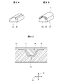
- FIG. 8A is a perspective view of a lower mold
- FIG. 8B is a perspective view showing stringers formed on the lower mold side of FIG. 8A
- FIG. 8C is a cross-sectional view showing stringers formed on the lower mold side.
- FIG. 9A is a diagram showing a modification of the preheating area
- FIG. 9B is a diagram showing another modification of the preheating area.
- FIG. 1A is a perspective view showing an object to be molded w
- FIG. 1B is a schematic perspective view showing the molding apparatus 100 of FIG. 1A
- FIG. is a perspective view showing a body panel).
- a molding apparatus 100 of the present embodiment shown in FIG. 1B molds a thin plate-shaped molding object w as shown in FIG. 1A so as to be curved in the thickness direction of the molding object w as shown in FIG. 1C.
- the object to be molded w is a prepreg laminate in which carbon fibers are impregnated with a thermoplastic resin prepared in advance.
- the above prepreg is an intermediate material in which fibers are impregnated with resin. After laminating this to form a laminate, fiber reinforced plastic (FRP) is manufactured through processes such as consolidation.
- the fiber reinforced plastic molded in this embodiment is a carbon fiber reinforced thermoplastic resin composite (CFRTP).
- the molding apparatus 100 of this embodiment includes an upper mold 1 and a lower mold 2.
- the lower surface of the upper mold 1 is formed in a concave shape
- the upper surface of the lower mold 2 is formed in a convex shape so as to be in close contact with the lower surface of the upper mold 1 .
- the object to be molded w is molded while being conveyed in the feed direction Ds by relative positional displacement between the upper mold 1 and the lower mold 2 .
- the object to be molded w is placed on the lower mold 2 and sent to a predetermined position along the feeding direction Ds. press .
- the object to be molded w is sent to the next predetermined position in the feeding direction Ds by the above-described relative positional displacement, and is pressed by the upper mold 1 at the predetermined position.
- the molding apparatus 100 repeats a cycle of conveying the molding object w and pressing the molding object w.
- the molding object w in which the curved surface shape is continuously formed in the longitudinal direction, as shown in FIG. 1C.
- a method for molding such an object w to be molded will be described in detail.
- the above-described feed direction Ds is used as a reference, and the width direction Dh is the direction perpendicular to the feed direction Ds in which the molding object w placed on the lower mold 2 extends.
- a direction orthogonal to both the feed direction Ds and the width direction Dh is defined as a height direction Dt.
- the above-described relative positional displacement between the upper mold 1 and the lower mold 2 is realized by moving the lower mold 2, but it is also included in the present disclosure that it is realized by moving the upper mold 1.
- the mold for placing the object w to be molded is described as the lower mold 2, and the mold facing it is described as the upper mold 1.
- the direction in which the two face each other does not have to match the direction of gravity as long as it does not deviate from the intent of the present disclosure.
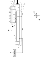
- FIG. 2 is a diagram showing the configuration of the molding apparatus 100 according to this embodiment
- FIG. 3 is a block diagram showing the configuration of the control system in the molding apparatus 100.
- the molding apparatus 100 includes an upper mold support section 3, a conveying device 4, a pressure receiving plate 5, and a control device 10 in addition to the upper mold 1 and the lower mold 2 described above. .
- control device 10 in the present disclosure may be general purpose processors, dedicated processors, integrated circuits, ASICs (Application Specific Integrated Circuits), conventional circuits, and/or those configured or programmed to perform the disclosed functions. can be performed using a circuit containing a combination, or a processing circuit.
- a processor is considered a processing circuit or circuit because it includes transistors and other circuits.
- a circuit, unit, or means is hardware that performs or is programmed to perform the recited functions.
- the hardware may be the hardware disclosed herein, or other known hardware programmed or configured to perform the recited functions.
- a circuit, means or unit is a combination of hardware and software where the hardware is a processor which is considered a type of circuit, the software being used to configure the hardware and/or the processor.
- the lower mold 2 is formed in, for example, a rectangular shape in plan view.
- the lower mold 2 is heated to a predetermined temperature and supports the object w to be molded.
- the melting point Tm of the molding object w is, for example, 305° C., but is not limited to this.
- the lower mold 2 is heated to a temperature lower than the melting point Tm of the molding object w, which is a predetermined temperature T11 in this embodiment.
- the predetermined temperature T11 is, for example, 300° C., but this predetermined temperature is not limited to this, either, and is determined appropriately based on the melting point Tm of the object to be molded w, for example, within the range of Tm ⁇ 10° C. .
- the temperature of the lower mold 2 is detected by a temperature sensor 43b such as a thermocouple or an infrared camera.
- a plurality of heaters 40b are provided in the lower mold 2.
- 12 heaters 40b are provided in the longitudinal direction of the molding object w, that is, the feed direction Ds, but the present invention is not limited to this.
- the number of control channels for the heaters 40b by the controller 10 for the lower die 2 (that is, the number equal to the total number of heaters 40b arranged) is 48.
- the temperature of the lower mold 2 is adjusted by controlling the heating operation of these heaters 40 b by the control device 10 .
- the lower mold 2 has a temperature range R11 (that is, a first lower mold temperature range) controlled to be the above-mentioned predetermined temperature T11 and a temperature range lower than the predetermined temperature T11.
- a temperature region R12 that is, the second lower mold temperature region
- T12 the length of the lower die 2 in the feed direction Ds is, for example, 2500 mm, it is not limited to this.
- the upper mold 1 is supported by the upper mold supporting portion 3.
- the upper mold 1 is configured to be bi-directionally movable in the height direction Dt and is arranged to face the lower mold 2 to press the object w to be molded.
- the upper die 1 has a plurality of temperature regions arranged side by side in the feeding direction Ds and temperature-controlled independently of each other by the control device 10 .
- the control device 10 controls the temperature regions arranged in the feeding direction Ds to have different temperatures.
- the upper mold 1 is provided with five temperature regions R1, R2, R3, R4, and R5. These temperature regions R1 to R5 are arranged in the feeding direction Ds.
- a plurality of heaters 40a are also provided in the upper mold 1, and at least one heater 40a is provided for each temperature region. The heating operation of the upper mold 1 by the heater 40 a is controlled by the controller 10 .
- one heater 40a is provided in each of the temperature regions R1, R3, R4, and R5, and two heaters 40a are provided in the temperature region R2, in the feeding direction Ds of the molding object w. .
- the width direction Dh for example, four heaters 40a are provided for each temperature region.
- heaters 40a are arranged in the feeding direction Ds of the molding object w, and four heaters 40a are arranged in the width direction Dh.
- the number equal to the total number of heaters 40a connected to each other) is 24, but is not limited to this.
- the transport device 4 includes a base portion 4a and a driving portion 4b.
- the lower mold 2 and the pressure receiving plate 5 are provided on the base portion 4a.
- the pressure receiving plates 5 are arranged at both ends of the lower die 2 in the feeding direction Ds and in the width direction Dh. Each pressure receiving plate 5 and the lower die 2 are in contact with each other.
- the driving section 4b of the conveying device 4 conveys the base section 4a supporting the lower mold 2 in the feed direction Ds.
- the driving portion 4b can be, for example, a gear mechanism and includes a rack gear, a pinion gear and an electric motor.
- the rotation of the pinion gear connected to the rotating shaft of the electric motor causes the rack gear provided on the base portion 4a to move in the feeding direction Ds.
- the base portion 4a moves in the feed direction Ds, and the lower die 2 can be moved in the feed direction Ds accordingly.
- the transport device 4 and its driving section 4b can appropriately select the method as long as the functions described above are exhibited and the essence of the present disclosure is not impaired.
- the drive source of the drive unit 4b may be an internal combustion engine.
- the control device 10 performs control so that the temperatures T1 to T5 in the temperature regions R1 to R5 are lowered from the upstream side to the downstream side (from the right side to the left side in FIG. 2) in the feeding direction Ds. Specifically, the temperature T1 of the temperature region R1 is heated to the process temperature Tp (for example, in the range of 350° C. to 400° C.), which is the highest temperature in each region.
- the process temperature Tp is a reference temperature for molding that is determined in consideration of the melting point Tm of the object to be molded w, and its temperature range is not limited to the range described above.
- the temperature region R2 is set to T2, which is lower than the temperature of the temperature region R1 and equal to or higher than the melting point Tm.
- the temperature T2 of the temperature region R2 is set to a temperature at which the viscosity of the molding object w starts to decrease when the molding object w is pressurized by the downstream end of the preheating region 1a, which will be described later. This is to allow pressure to be applied to the
- the temperatures T1 to T5 of the temperature regions R1 to R5 of the upper mold 1 are detected by the temperature sensor 43a in the same manner as the lower mold 2.
- the temperatures T3 to T5 of the temperature regions R3, R4, and R5 of the upper mold 1 are set to satisfy T2>T3>T4>T5 as described above.
- the temperature range of the temperatures T3 to T5 is set to be, for example, 50° C. to 150° C. lower than the process temperature Tp, but is not limited to this.
- the length of the upper mold 1 in the feed direction Ds in this embodiment is, for example, 1080 mm
- the length of the upper mold 2 in the feed direction Ds is not limited to this.
- the lengths of the upper mold 1 and the lower mold 2 in the feeding direction Ds may be changed, for example, by the length of the molding object w in the feeding direction Ds.
- the lengths and the number of temperature regions R1, R2, R3, R4, and R5 of the upper mold 1 in the feed direction Ds also include the lengths of the upper mold 1 itself and the object to be molded w in the feed direction Ds. , and is determined in association with a predetermined amount of movement of the base portion 4a in the feeding direction Ds, which will be described later.
- the upper die 1 has a preheating area 1a arranged upstream in the feeding direction Ds, and a downstream heating area 1b arranged downstream of the preheating area 1a in the feeding direction Ds.
- the preheating region 1a is arranged at a position spanning the temperature regions R1 and R2
- the downstream heating region 1b is arranged at a position spanning the temperature regions R3, R4, and R5.
- Such a preheating area 1a is spaced apart from the molding object w when the downstream heating area 1b is in contact with the molding object w. That is, the thickness in the height direction Dt of the preheating region 1a is smaller than the thickness in the height direction Dt of the downstream heating region 1b.
- the temperature regions R1 and R2 of the upper mold 1 do not touch the molding object w, whereas the temperature regions R3 to R5 intermittently touch the molding object w. Contact and separation with the molding object w are repeated.
- the preheating region 1a in order to realize the above-described spaced apart arrangement of the preheating region 1a with respect to the object w to be molded, the preheating region 1a has one or more of a horizontal surface, an inclined surface, and a curved surface on the side of the object w to be molded. have a face.
- FIG. 2 shows an example in which the surface of the preheating area 1a on the molding object w side is an inclined surface.
- each of the temperature regions R1 to R5 has been described above, but the minimum necessary in the present disclosure
- the temperature of the entire preheating region 1a is higher than the melting point of the molding object w
- the temperature of the downstream heating region 1b is lower than the melting point of the molding object w
- the temperature of the lower mold 2 is It is preferable that each temperature be set so that the temperature is lower than the melting point of the molding object w and equal to or higher than the temperature of the downstream heating region 1b.
- it is effective in promoting resin crystallization in the consolidation of the molding object w. has been found from experiments, and the configuration described above is adopted.
- FIG. 4A is a diagram for explaining the first preheating step of the molding object w
- FIG. 4B is a diagram for explaining the first consolidation step
- 5A and 5B are diagrams for explaining the second and subsequent consolidation steps, the transfer of the molding object w, and the changing step of the temperature region ratio of the lower mold 2.
- the steps shown in FIG. 4A are as follows. First, the downstream end portion (the left end portion in the drawing) of the flat plate-shaped molding object w is first preheated (that is, heated before pressurization). In this case, the preheating region 1a (portion corresponding to the temperature regions R1 and R2) of the upper mold 1 is arranged at a distance from the downstream end of the molding object w. to heat. As a result, the temperature of the downstream end of the object to be molded w rises. A single temperature region R11 is formed in the lower mold 2 at this time.
- the base portion 4a is moved by a predetermined amount in the feeding direction Ds.
- the amount of movement is, for example, 1/10 of the length of the object to be molded w in the feeding direction Ds.
- the object to be molded w moves in the feeding direction Ds by a predetermined amount.
- the downstream end of the molding object w is pressurized.
- the downstream end of the molding object w is pressurized (consolidated) by the temperature region R3 of the upper mold 1 and the temperature region R11 of the lower mold 2 .
- the pressurization time is, for example, 10 seconds or more, but is not limited to this.
- a portion (eg, central portion) upstream of the downstream end of the molding object w is positioned so as to overlap the preheating area 1a when viewed from the height direction Dt of the preheating area 1a. Therefore, preheating is performed at the same time in this process for the part on the upstream side of the downstream end of the object to be molded w.
- the object to be molded w and the preheating region 1a are not in contact with each other. Therefore, preheating is performed by heat radiation from the preheating area 1a or by convection of the air warmed by the preheating area 1a.
- the steps shown in FIG. 5A are as follows. While the upper die 1 is raised, the base portion 4a is moved by a predetermined amount in the feeding direction Ds. Along with this, the object to be molded w moves in the feeding direction Ds by a predetermined amount.
- the lower die 2 is controlled by means described later so as to change from a state having a single temperature region R11 to a state having both temperature regions R11 and R12 arranged side by side in the feed direction Ds.
- the temperature region R12 is formed downstream of the temperature region R11.
- the boundary line between the temperature regions R11 and R12 is set at a position overlapping the temperature region R3 of the upper mold when viewed from above in the height direction Ds.
- downstream end of the molding object w has moved to a position overlapping the temperature region R4 or the temperature region R5 of the upper mold when viewed from the upper side in the height direction Ds (in the present embodiment, the temperature region R5 overlapping positions).
- pressure is applied to the downstream end of the object to be molded w and a portion upstream of the downstream end.
- the downstream end of the molding object w is cooled by the temperature regions R4 and R5 in the upper mold 1 and the temperature region R12 in the lower mold 2, and the temperature in the temperature region R3 in the upper mold 1 and the temperature in the lower mold 2
- the region R11 pressurizes (consolidates) the portion upstream of the downstream end of the object to be molded w.
- the portion is preheated since the central portion of the molding object w is located below the preheating region 1a, the portion is preheated.
- the downstream temperature region 1b of the upper mold 1 includes a consolidation heating region (that is, the temperature region R3) for consolidating the molding object w and a cooling region (that is, the temperature region R4 and R5).
- a pipe (not shown) is provided in the lower die 2 for circulating the cooling medium.
- a cooling medium such as air or water is circulated through the piping by the pump 41 (FIG. 3), whereby the lower die 2 can be cooled by water cooling.
- a cooling means for the lower die 2 an air-cooling system using a fan 42 (FIG. 3) may be employed, or the above-described water-cooling system and air-cooling system may be used together.
- the ratio between the temperature region R12 and the temperature region R11 of the lower mold 2 is changed by the control device 10. Specifically, since the temperature regions R4 and R5 of the upper mold 1 move in the feed direction Ds as the molding object w is conveyed, the boundary line between the temperature regions R11 and R12 is In the embodiment, it is set at a position overlapping the temperature region R3 of the upper die when viewed from above in the height direction Ds. As a result, in the second and subsequent consolidation steps, when the temperature regions R4 and R5 of the upper mold come into contact with the object w to be molded, the temperature regions R4 and R5 are always lowered when viewed from above in the height direction Ds. It is arranged at a position overlapping the temperature region R12 of the mold.
- each step of conveying, consolidating, and cooling the object w to be molded is performed only by the upper mold 1 and the lower mold 2 without providing a dedicated structure for conveying the object to be molded w. can be carried out, and therefore molding of thermoplastic resin products can be performed in a highly time-efficient manner.
- the temperature T12 of the temperature region R12 of the lower mold 2 is set to satisfy T11>T12 as described above.
- the temperature T12 is set to a temperature lower than the melting point Tm of the molding object w by 50° C. to 150° C., but is not limited to this.
- the state shown in FIG. 6 is reached through the movement of the base portion 4a in the feeding direction Ds, the change in the ratio of the temperature regions R11 and R12 of the lower mold 2, and the descent of the upper mold 1. Also in the state of FIG. 6, the two steps described with reference to FIG. 5B are performed, and these two steps are repeated thereafter. As a result, the positions of the object to be molded w to be consolidated by the upper mold 1 and the lower mold 2 are changed stepwise from the downstream side to the upstream side. When the cooling pressure in the second and subsequent consolidation steps reaches the upstream end of the object w, the entire molding process of the object w in the molding apparatus 100 of this embodiment is completed.
- the upper mold 1 and the lower mold 2 perform one-time molding of the object w to be molded.
- the preheating, consolidation, and cooling processes can be performed simultaneously, and can be performed continuously in the feed direction Ds for the molding object w.
- FIG. 7 is a flow chart showing the flow of the molding process by the molding apparatus 100 of this embodiment.
- step S0-1 the object to be molded w is supported by the lower mold 2 (step S0-1). Then, the temperature regions R1 to R5 are formed in the upper mold 1 and the temperature region R11 is formed in the lower mold 2 by the control device 10 (step S0-2). After the preparatory step, the main step below is carried out.
- the molding object w is first preheated (step S1).
- the object to be molded w is moved by a predetermined amount in the feeding direction Ds (step S2).
- a first consolidation step is performed (step S3).
- the portion of the molding object w preheated in step S1 is subjected to consolidation (pressurization) and the feeding direction Ds as viewed from the consolidation portion. Preheating of the upstream portion is performed simultaneously.
- step S4 the ratio of temperature range R12 to temperature range R11 is 0, but temperature range R12 is formed when step S4 is performed for the first time. As will be described later, step S4 is repeated several times, but the ratio of temperature range R12 to temperature range R11 increases as step S4 is performed.
- step S5 the second and subsequent consolidation steps are carried out.
- step S5 as described above, the portion of the molding object w consolidated in step S4 is cooled and the portion of the molding object w preheated in step S4 is subjected to consolidation ( Pressurization) and preheating of the portion on the upstream side in the feed direction Ds as seen from the portion being consolidated are all performed at the same time.
- step S6 if there is a portion to be pressurized on the object w to be molded (NO in step S6), the process returns to step S4. On the other hand, if there is no portion to be pressurized on the object to be molded w (YES in step S6), the molding process is terminated.
- the lower mold 2 supporting the molding object w is relatively conveyed with respect to the upper mold 1 in the feeding direction Ds by the conveying device 4 .
- a first temperature region R11 and a second temperature region R12 whose temperature is controlled are formed side by side in the feeding direction Ds in the lower die 2 .
- the ratio of R12 to the temperature region R11 of the lower mold 2 in the feed direction Ds changes according to the relative position between the upper mold 1 and the lower mold 2 . That is, as the lower mold 2 is fed forward, the temperature region R11 becomes smaller and the temperature region R12 becomes larger.
- a dedicated configuration for transportation can be omitted. can.
- the pressurized portion is sequentially cooled. As a result, it is possible to shorten the production time and reduce the cost of the apparatus.
- a plurality of temperature regions are provided side by side in the feeding direction Ds, and are sequentially from the upstream side to the downstream side, the preheating region 1a, and the temperature from the preheating region 1a.
- a downstream heating region 1b having a lower temperature is also formed.
- the preheating region 1a enables preheating of the object w to be molded before pressure molding, and the downstream heating region 1b enables consolidation of the object w to be molded.
- preheating of the object w to be molded and consolidation to pressurize the object w to be molded at a temperature lower than that of the preheating are performed in one pressurizing step performed by the upper mold 1 and the lower mold 2. , can be simultaneously applied to different parts of the object to be molded w.
- the downstream heating region 1b a plurality of temperature regions provided side by side in the feed direction Ds, which are temperature regions R3, which are consolidation temperature regions, in order from the upstream side to the downstream side. , cooling regions R4 and R5 having a lower temperature than the temperature region R3.
- the cooling process for further lowering the temperature can be performed simultaneously with the above-described pressurizing process, and the production time can be further shortened.
- the preheating region 1a of the upper mold 1 is set to a temperature equal to or higher than the melting point Tm of the molding object w
- the downstream heating region 1b is set to a temperature lower than the melting point of the molding object w.
- the control device 10 controls the control device 10 so that By changing the temperature to be applied according to the parameters of the object to be molded w, one molding apparatus 100 can handle a plurality of types of molded products.
- the temperature setting of the temperature region of the lower mold 2 is also controlled by the control device 10 so that it is equal to or higher than the temperature of the surface of the downstream heating region of the upper mold 1 and lower than the melting point Tm of the molding object w. be.
- the preheating region 1a and the molding object w are separated from each other when the upper mold 1 and the lower mold 2 apply pressure to the molding object w.
- the preheating part 1a has a smaller thickness than the downstream heating part 1b so that when the downstream heating part 1b is pressed against the molding object w, the preheating part 1a is separated from the molding object w.
- the temperature range of the downstream heating section 1b is set to a temperature higher than that of the preheating section 1a.
- the thickest region of the upper mold 1 is set to a temperature lower than the other thinner temperature regions of the upper mold 1 .
- the upper die 1 in the present invention adopts the above-described shape for the purpose of carrying out preheating in a non-contact manner.
- a molding apparatus 100 can mold an object to be molded w having a stringer 21 with a hat-shaped cross section on the surface to be molded by the lower mold 2a.
- the stringer 21 is installed in the recess 22 provided in advance in the lower mold 2 a , and then the core 20 is inserted into the recess of the stringer 21 .
- the object to be molded w is placed along the surfaces of the lower mold 2a and the core 20, and molding is performed in the same manner as in the above embodiment.
- the temperature of the lower mold 2a is set to a temperature lower than the melting point of the stringer 21 and equal to or higher than the temperature of the downstream heating region 1b.
- the object w to be molded and the stringer 21 are integrally molded. Note that the core 20 is removed after integral molding.
- the stringer 21 is formed on the lower mold 2a side of the object to be molded w, but the present disclosure also includes a configuration in which the stringer is formed on the upper mold 1 side. In this case, the recess 22 is provided in the upper mold 1 .
- an upper die 30 may be employed which has a preheating area 1a1 partially or entirely formed of a horizontal surface and partitioned from the downstream heating area 1b by a step.
- an upper die 31 having a preheating region 1a2 including a curved surface may be employed.
- the connecting portion between the downstream heating region 1b and the preheating region 1a is preferably changed continuously to some extent.
- the lower mold 2 is moved in the feeding direction Ds by the conveying device 4 in order to relatively convey the lower mold 2 and the upper mold 1 in the feeding direction Ds.
- the upper mold 1 may be moved in the feeding direction Ds, or both the upper mold 1 and the lower mold 2 may be moved.
- the upper mold 1 moves in the height direction Dt when consolidation is performed. 2 may move.
- the relative movement in each direction between the upper mold 1 and the lower mold 2 in the present disclosure can be realized by any means or method.
- the upper die 1 and the lower die 2 do not move relative to each other in the width direction Dh. 1 and the lower mold 2 may be configured.
- the stringers and the upper mold 1 or the lower mold 2 In order to avoid contact with the upper mold 1 and the lower mold 2, the relative movement may be performed simultaneously in the height direction Dt and the width direction Dh.
- the present disclosure can be suitably applied to the manufacture of parts for relatively large equipment such as aircraft, but can also be applied to the manufacture of thermosetting resin parts for various other articles.
- the object to be molded in the present embodiment is a carbon fiber reinforced thermoplastic resin molded product, it can be used for molding a thermoplastic resin molded product reinforced with glass fiber, for example, and can be fiber reinforced. It can also be used to mold thermoplastic resin parts that do not require
Landscapes
- Engineering & Computer Science (AREA)
- Mechanical Engineering (AREA)
- Chemical & Material Sciences (AREA)
- Composite Materials (AREA)
- Casting Or Compression Moulding Of Plastics Or The Like (AREA)
- Moulding By Coating Moulds (AREA)
Priority Applications (3)
| Application Number | Priority Date | Filing Date | Title |
|---|---|---|---|
| EP22842103.8A EP4371726A4 (en) | 2021-07-13 | 2022-07-12 | MOLDING DEVICE AND MOLDING METHOD |
| US18/408,637 US20240149503A1 (en) | 2021-07-13 | 2024-01-10 | Molding device and molding method |
| US19/303,553 US20250381713A1 (en) | 2021-07-13 | 2025-08-19 | Molding device and molding method |
Applications Claiming Priority (2)
| Application Number | Priority Date | Filing Date | Title |
|---|---|---|---|
| JP2021115704A JP2023012200A (ja) | 2021-07-13 | 2021-07-13 | 成形装置および成形方法 |
| JP2021-115704 | 2021-07-13 |
Related Child Applications (1)
| Application Number | Title | Priority Date | Filing Date |
|---|---|---|---|
| US18/408,637 Continuation US20240149503A1 (en) | 2021-07-13 | 2024-01-10 | Molding device and molding method |
Publications (1)
| Publication Number | Publication Date |
|---|---|
| WO2023286759A1 true WO2023286759A1 (ja) | 2023-01-19 |
Family
ID=84919490
Family Applications (1)
| Application Number | Title | Priority Date | Filing Date |
|---|---|---|---|
| PCT/JP2022/027370 Ceased WO2023286759A1 (ja) | 2021-07-13 | 2022-07-12 | 成形装置および成形方法 |
Country Status (4)
| Country | Link |
|---|---|
| US (2) | US20240149503A1 (https=) |
| EP (1) | EP4371726A4 (https=) |
| JP (1) | JP2023012200A (https=) |
| WO (1) | WO2023286759A1 (https=) |
Families Citing this family (1)
| Publication number | Priority date | Publication date | Assignee | Title |
|---|---|---|---|---|
| US11904510B2 (en) * | 2022-02-10 | 2024-02-20 | The Boeing Company | Continuous compression molding machines and methods of continuous compression molding a consolidated thermoplastic matrix composite material |
Citations (5)
| Publication number | Priority date | Publication date | Assignee | Title |
|---|---|---|---|---|
| JP2017154409A (ja) * | 2016-03-03 | 2017-09-07 | パナソニックIpマネジメント株式会社 | 熱プレス成形方法および熱プレス成形装置 |
| JP2018089825A (ja) | 2016-12-01 | 2018-06-14 | 川崎重工業株式会社 | 複合材料構造物の製造方法 |
| US10029426B2 (en) | 2010-04-02 | 2018-07-24 | Airbus Operations Gmbh | Device for producing a fiber-reinforced thermoplastic composite component |
| JP2020152110A (ja) * | 2019-03-19 | 2020-09-24 | ザ・ボーイング・カンパニーThe Boeing Company | 熱可塑性複合材部品のココンソリデーション用の方法とシステム |
| JP6766268B1 (ja) | 2019-03-08 | 2020-10-07 | 株式会社Ihiエアロスペース | Frp成形システムと方法 |
Family Cites Families (5)
| Publication number | Priority date | Publication date | Assignee | Title |
|---|---|---|---|---|
| US5839088A (en) * | 1996-08-22 | 1998-11-17 | Go2 Software, Inc. | Geographic location referencing system and method |
| JP2006255923A (ja) * | 2005-03-15 | 2006-09-28 | Ricoh Co Ltd | 光学素子の製造方法,光学素子およびミラーレンズならびに走査レンズ |
| DE102013226753A1 (de) * | 2013-12-19 | 2015-06-25 | Airbus Operations Gmbh | Vorrichtung und Verfahren zur kontinuierlichen Fertigung von Strukturbauteilen aus faserverstärkten Verbundmaterialien sowie Formwerkzeugset |
| JP6697819B2 (ja) * | 2016-04-21 | 2020-05-27 | 三菱重工業株式会社 | 複合材料成形装置及び複合材料成形方法 |
| JP2021037709A (ja) * | 2019-09-04 | 2021-03-11 | 住友ベークライト株式会社 | 成形体の製造方法 |
-
2021
- 2021-07-13 JP JP2021115704A patent/JP2023012200A/ja active Pending
-
2022
- 2022-07-12 EP EP22842103.8A patent/EP4371726A4/en active Pending
- 2022-07-12 WO PCT/JP2022/027370 patent/WO2023286759A1/ja not_active Ceased
-
2024
- 2024-01-10 US US18/408,637 patent/US20240149503A1/en active Pending
-
2025
- 2025-08-19 US US19/303,553 patent/US20250381713A1/en active Pending
Patent Citations (5)
| Publication number | Priority date | Publication date | Assignee | Title |
|---|---|---|---|---|
| US10029426B2 (en) | 2010-04-02 | 2018-07-24 | Airbus Operations Gmbh | Device for producing a fiber-reinforced thermoplastic composite component |
| JP2017154409A (ja) * | 2016-03-03 | 2017-09-07 | パナソニックIpマネジメント株式会社 | 熱プレス成形方法および熱プレス成形装置 |
| JP2018089825A (ja) | 2016-12-01 | 2018-06-14 | 川崎重工業株式会社 | 複合材料構造物の製造方法 |
| JP6766268B1 (ja) | 2019-03-08 | 2020-10-07 | 株式会社Ihiエアロスペース | Frp成形システムと方法 |
| JP2020152110A (ja) * | 2019-03-19 | 2020-09-24 | ザ・ボーイング・カンパニーThe Boeing Company | 熱可塑性複合材部品のココンソリデーション用の方法とシステム |
Non-Patent Citations (1)
| Title |
|---|
| See also references of EP4371726A4 |
Also Published As
| Publication number | Publication date |
|---|---|
| US20240149503A1 (en) | 2024-05-09 |
| US20250381713A1 (en) | 2025-12-18 |
| JP2023012200A (ja) | 2023-01-25 |
| EP4371726A4 (en) | 2025-07-16 |
| EP4371726A1 (en) | 2024-05-22 |
Similar Documents
| Publication | Publication Date | Title |
|---|---|---|
| US8545201B2 (en) | Curing system using electromagnetic force | |
| CN101815609B (zh) | 连续压制装置 | |
| CN107614232A (zh) | 层叠装置 | |
| US10913222B2 (en) | Method for producing composite material component and device for producing composite material component | |
| CN108025483B (zh) | 复合材料的制造方法、复合材料的制造装置、复合材料用预制件以及复合材料 | |
| US20250381713A1 (en) | Molding device and molding method | |
| JPWO2008149801A1 (ja) | プレス装置及びプレス装置システム | |
| CN103025449A (zh) | 用热压机进行的钢板成型方法 | |
| CN112996653A (zh) | Frp成形系统和方法 | |
| EP2889126B1 (en) | Method for producing composite material mold for composite material long member | |
| EP4137298A1 (en) | Processing apparatus for composite material and processing method for composite material | |
| TW201332745A (zh) | 熱壓成型方法 | |
| US11046029B2 (en) | Method for producing composite material component and device for producing composite material component | |
| JP2023012200A5 (https=) | ||
| JP6543940B2 (ja) | 複合材料の成形方法および成形装置 | |
| CN114516157A (zh) | 复合夹芯板热压成型冷却定型装置 | |
| JP2017530040A (ja) | 熱可塑性材料の加熱成形方法および実施設備 | |
| JP7310027B2 (ja) | 賦形装置および賦形方法 | |
| JP2000309033A (ja) | 射出成形同時絵付方法及び装置 | |
| JP7596332B2 (ja) | 成形装置及び成形方法 | |
| US12257761B2 (en) | Thermoforming system | |
| JP2871783B2 (ja) | 複合材の成形方法および成形装置 | |
| JP7825718B2 (ja) | 複合材部品の製造方法、および、複合材部品製造装置 | |
| TWI329568B (https=) | ||
| JP2025183514A (ja) | 連続プレス成形装置、成形品、及び連続プレス成形方法 |
Legal Events
| Date | Code | Title | Description |
|---|---|---|---|
| 121 | Ep: the epo has been informed by wipo that ep was designated in this application |
Ref document number: 22842103 Country of ref document: EP Kind code of ref document: A1 |
|
| WWE | Wipo information: entry into national phase |
Ref document number: 2022842103 Country of ref document: EP |
|
| NENP | Non-entry into the national phase |
Ref country code: DE |
|
| ENP | Entry into the national phase |
Ref document number: 2022842103 Country of ref document: EP Effective date: 20240213 |