WO2023286704A1 - 弾性波装置、フィルタ、分波器及び通信装置 - Google Patents
弾性波装置、フィルタ、分波器及び通信装置 Download PDFInfo
- Publication number
- WO2023286704A1 WO2023286704A1 PCT/JP2022/027079 JP2022027079W WO2023286704A1 WO 2023286704 A1 WO2023286704 A1 WO 2023286704A1 JP 2022027079 W JP2022027079 W JP 2022027079W WO 2023286704 A1 WO2023286704 A1 WO 2023286704A1
- Authority
- WO
- WIPO (PCT)
- Prior art keywords
- electrode
- elastic wave
- electrode fingers
- region
- filter
- Prior art date
- Legal status (The legal status is an assumption and is not a legal conclusion. Google has not performed a legal analysis and makes no representation as to the accuracy of the status listed.)
- Ceased
Links
Images








Classifications
-
- H—ELECTRICITY
- H03—ELECTRONIC CIRCUITRY
- H03H—IMPEDANCE NETWORKS, e.g. RESONANT CIRCUITS; RESONATORS
- H03H9/00—Networks comprising electromechanical or electro-acoustic elements; Electromechanical resonators
- H03H9/25—Constructional features of resonators using surface acoustic waves
-
- H—ELECTRICITY
- H03—ELECTRONIC CIRCUITRY
- H03H—IMPEDANCE NETWORKS, e.g. RESONANT CIRCUITS; RESONATORS
- H03H9/00—Networks comprising electromechanical or electro-acoustic elements; Electromechanical resonators
- H03H9/02—Details
- H03H9/02535—Details of surface acoustic wave devices
- H03H9/02543—Characteristics of substrate, e.g. cutting angles
- H03H9/02574—Characteristics of substrate, e.g. cutting angles of combined substrates, multilayered substrates, piezoelectrical layers on not-piezoelectrical substrate
-
- H—ELECTRICITY
- H03—ELECTRONIC CIRCUITRY
- H03H—IMPEDANCE NETWORKS, e.g. RESONANT CIRCUITS; RESONATORS
- H03H9/00—Networks comprising electromechanical or electro-acoustic elements; Electromechanical resonators
- H03H9/02—Details
- H03H9/02535—Details of surface acoustic wave devices
- H03H9/02992—Details of bus bars, contact pads or other electrical connections for finger electrodes
-
- H—ELECTRICITY
- H03—ELECTRONIC CIRCUITRY
- H03H—IMPEDANCE NETWORKS, e.g. RESONANT CIRCUITS; RESONATORS
- H03H9/00—Networks comprising electromechanical or electro-acoustic elements; Electromechanical resonators
- H03H9/02—Details
- H03H9/125—Driving means, e.g. electrodes, coils
- H03H9/145—Driving means, e.g. electrodes, coils for networks using surface acoustic waves
-
- H—ELECTRICITY
- H03—ELECTRONIC CIRCUITRY
- H03H—IMPEDANCE NETWORKS, e.g. RESONANT CIRCUITS; RESONATORS
- H03H9/00—Networks comprising electromechanical or electro-acoustic elements; Electromechanical resonators
- H03H9/02—Details
- H03H9/125—Driving means, e.g. electrodes, coils
- H03H9/145—Driving means, e.g. electrodes, coils for networks using surface acoustic waves
- H03H9/14544—Transducers of particular shape or position
-
- H—ELECTRICITY
- H03—ELECTRONIC CIRCUITRY
- H03H—IMPEDANCE NETWORKS, e.g. RESONANT CIRCUITS; RESONATORS
- H03H9/00—Networks comprising electromechanical or electro-acoustic elements; Electromechanical resonators
- H03H9/02—Details
- H03H9/125—Driving means, e.g. electrodes, coils
- H03H9/145—Driving means, e.g. electrodes, coils for networks using surface acoustic waves
- H03H9/14544—Transducers of particular shape or position
- H03H9/1457—Transducers having different finger widths
-
- H—ELECTRICITY
- H03—ELECTRONIC CIRCUITRY
- H03H—IMPEDANCE NETWORKS, e.g. RESONANT CIRCUITS; RESONATORS
- H03H9/00—Networks comprising electromechanical or electro-acoustic elements; Electromechanical resonators
- H03H9/46—Filters
- H03H9/64—Filters using surface acoustic waves
-
- H—ELECTRICITY
- H03—ELECTRONIC CIRCUITRY
- H03H—IMPEDANCE NETWORKS, e.g. RESONANT CIRCUITS; RESONATORS
- H03H9/00—Networks comprising electromechanical or electro-acoustic elements; Electromechanical resonators
- H03H9/46—Filters
- H03H9/64—Filters using surface acoustic waves
- H03H9/6423—Means for obtaining a particular transfer characteristic
- H03H9/6433—Coupled resonator filters
- H03H9/6483—Ladder SAW filters
-
- H—ELECTRICITY
- H03—ELECTRONIC CIRCUITRY
- H03H—IMPEDANCE NETWORKS, e.g. RESONANT CIRCUITS; RESONATORS
- H03H9/00—Networks comprising electromechanical or electro-acoustic elements; Electromechanical resonators
- H03H9/70—Multiple-port networks for connecting several sources or loads, working on different frequencies or frequency bands, to a common load or source
- H03H9/72—Networks using surface acoustic waves
-
- H—ELECTRICITY
- H03—ELECTRONIC CIRCUITRY
- H03H—IMPEDANCE NETWORKS, e.g. RESONANT CIRCUITS; RESONATORS
- H03H9/00—Networks comprising electromechanical or electro-acoustic elements; Electromechanical resonators
- H03H9/70—Multiple-port networks for connecting several sources or loads, working on different frequencies or frequency bands, to a common load or source
- H03H9/72—Networks using surface acoustic waves
- H03H9/725—Duplexers
Definitions
- the present disclosure provides an acoustic wave device capable of at least one of conversion from an acoustic wave to an electrical signal and conversion from an electrical signal to an acoustic wave, a filter including the acoustic wave device, and a demultiplexer including the filter. and a communication device including the branching filter.
- Patent Document 1 As an elastic wave device, one having a piezoelectric layer and an IDT (Interdigital Transducer) electrode positioned on the piezoelectric layer is known (for example, Patent Document 1 below).
- the IDT electrode has a pair of comb electrodes.
- Each comb tooth electrode has a bus bar and a plurality of electrode fingers extending in parallel from the bus bar.
- a pair of comb-teeth electrodes are arranged so as to mesh with each other.
- Patent Literature 1 discloses an IDT electrode in which a busbar is provided with a plurality of openings arranged in the direction in which the busbar extends.
- An elastic wave device includes a piezoelectric body having a first surface and an IDT electrode positioned on the first surface.
- the IDT electrode has a first bus bar, a second bus bar, a plurality of first electrode fingers, a plurality of second electrode fingers, a plurality of bar electrodes, and a plurality of connection portions.
- the second busbar faces the first busbar.
- the plurality of first electrode fingers are electrically connected to the first bus bar.
- the plurality of second electrode fingers are electrically connected to the second bus bar, respectively, and arranged alternately with the plurality of first electrode fingers in the elastic wave propagation direction.
- the plurality of bar electrodes are interposed between the first bus bars and between the plurality of first electrode fingers, extend parallel to the first bus bars, and extend parallel to each other.
- the plurality of connection portions include a connection portion interposed between and connecting the first bus bar and the bar electrode adjacent to the first bus bar, and a connection portion interposed between the adjacent bar electrodes and connecting the two. and connecting connections. At least some of the plurality of connecting portions are arranged discontinuously with respect to the extending direction of the plurality of first electrode fingers.
- a filter according to an aspect of the present disclosure is located on the elastic wave device and the first surface, and is connected to the IDT electrode in a ladder shape to form a ladder filter. and an IDT electrode.
- a filter according to an aspect of the present disclosure is positioned on the elastic wave device and the first surface, and arranged in the elastic wave propagation direction with respect to the IDT electrode to form a multimode filter. and one or more other IDT electrodes.
- a duplexer includes an antenna terminal, a transmission filter connected to the antenna terminal, and a reception filter connected to the antenna terminal. At least one of the transmission filter and the reception filter is configured by one of the above filters.
- a communication device includes the branching filter described above, an antenna connected to the antenna terminal, and an IC (Integrated Circuit) connected to the transmission filter and the reception filter. are doing.
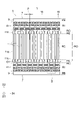
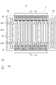
- FIG. 2 is an enlarged view of region II in FIG. 1 and shows a part of a specific example of an IDT electrode;
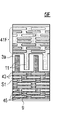
- FIG. 10 is a diagram showing another specific example (second example) of an IDT electrode;
- FIG. 10 is a diagram showing still another specific example (third example) of an IDT electrode;
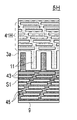
- FIG. 10 is a diagram showing still another specific example (fourth example) of an IDT electrode;
- FIG. 10 is a diagram showing still another specific example (fifth example) of the IDT electrode;
- FIG. 10 is a diagram showing still another specific example (sixth example) of an IDT electrode;
- FIG. 10 is a diagram showing still another specific example (seventh example) of the IDT electrode;
- FIG. 10 is a diagram showing another specific example (seventh example) of the IDT electrode;
- FIG. 10 is a diagram showing another specific example (second example) of an IDT electrode;
- FIG. 10 is a diagram showing another specific example (second example) of an IDT electrode;
- FIG. 10 is a diagram showing still another specific example (eighth example) of an IDT electrode;
- FIG. 10 is a diagram showing still another specific example (ninth example) of the IDT electrode;
- FIG. 10 is a diagram showing still another specific example (tenth example) of the IDT electrode;
- FIG. 10 is a diagram showing still another specific example (eleventh example) of an IDT electrode;
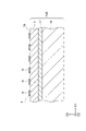
- FIG. 2 is a diagram showing an example of a cross section taken along line VI-VI of FIG. 1;
- 2 is a diagram showing another example of a cross section taken along the line VI-VI of FIG. 1;
- FIG. 1 is a plan view showing the configuration of an elastic wave resonator according to an embodiment;
- FIG. 1 is a circuit diagram schematically showing the configuration of a branching filter according to an embodiment
- FIG. 1 is a block diagram showing the configuration of a communication device according to an embodiment
- FIG. FIG. 5 is a diagram showing characteristics of resonators according to the first comparative example and the first example
- FIG. 5 is a diagram showing characteristics of resonators according to first to third examples
- FIG. 10 is a diagram showing characteristics of resonators according to second and third comparative examples and a fourth example;
- any direction of the elastic wave device according to the present disclosure may be upward or downward.
- an orthogonal coordinate system consisting of the D1 axis, the D2 axis and the D3 axis is defined, and terms such as the upper surface and the lower surface may be used with the positive side of the D3 axis being the upper side.
- the term "planar view” or “planar see-through” refers to viewing in the D3 direction.
- the D1 axis is defined to be parallel to the propagation direction of an elastic wave propagating along the upper surface of the piezoelectric body, which will be described later, and the D2 axis is defined to be parallel to the upper surface of the piezoelectric body and perpendicular to the D1 axis. and the D3 axis is defined to be orthogonal to the top surface of the piezoelectric.
- FIG. 1 is a plan view showing a configuration of a main part of an elastic wave device 1 (hereinafter sometimes simply referred to as "device 1") according to an embodiment.
- the device 1 has, for example, a piezoelectric body 3 (see FIG. 6 and the like, which will be described later), and an IDT electrode 5 located on the upper surface 3a (an example of the first surface) of the piezoelectric body 3.
- FIG. 1 is a plan view of the upper surface 3a. However, the reference numerals relating to the piezoelectric body 3 and the outer edge of the upper surface 3a are omitted from the illustration.
- the device 1 may, for example, constitute resonators and/or filters that utilize such conversion between acoustic waves and voltages (electrical signals).
- the D1 direction may be referred to as an elastic wave propagation direction or a propagation direction.
- the IDT electrode 5 is composed of a conductor layer overlapping the upper surface 3 a of the piezoelectric body 3 . Also, the IDT electrode 5 includes a pair of comb electrodes 7 . Each comb-teeth electrode 7 includes, for example, a busbar 9 and a plurality of electrode fingers 11 electrically connected to the busbar 9 . A pair of comb-teeth electrodes 7 are arranged such that a plurality of electrode fingers 11 mesh with each other (intersect each other).
- the intersection region R0 is a region in which the plurality of electrode fingers 11 of one comb-shaped electrode 7 and the plurality of electrode fingers 11 of the other comb-shaped electrode 7 overlap in the elastic wave propagation direction.
- each comb-teeth electrode 7 has an intervening electrode 41 interposed between the busbar 9 and the plurality of electrode fingers 11 .
- transverse mode spurious can be reduced, as will be described in detail later.
- the configuration other than the configuration related to the intervening electrode 41 may be in various modes, for example, it may be in a known mode. A description of such a configuration that may be a known aspect will be omitted as appropriate.
- the bus bar 9 is formed, for example, in an elongated shape having a substantially constant width and linearly extending in the elastic wave propagation direction (D1 direction).
- the pair of busbars 9 face each other in a direction (D2 direction) perpendicular to the elastic wave propagation direction.
- the edge of each busbar 9 on the side of the intersection region R0 is, for example, linear.
- the edges on the intersection region R0 side are, for example, parallel to each other (the concept of "parallel” may be extended to "curve”). From another point of view, the distance between both edges (D2 direction) is constant regardless of the position in the D1 direction.
- the busbar 9 may vary in width or may be inclined with respect to the propagation direction of the elastic wave. Further, in each bus bar 9, the edge portion on the intersection region R0 side may be curved, or may be formed by a plurality of straight lines that intersect with each other. Also, in the pair of busbars 9, the distance between the edges facing each other may vary depending on the position in the D1 direction.
- the length (D1 direction) of the bus bar 9 may be approximately equal to the product of the pitch p and the number of the plurality of electrode fingers 11 in the pair of comb-teeth electrodes 7, for example.
- the width (D2 direction) of the bus bar 9 is arbitrary. In general, the width of bus bar 9 is greater than the width of electrode fingers 11 (D1 direction). For example, the width of the busbar 9 may be 1p or more.
- the plurality of electrode fingers 11 have, for example, the same shape and dimensions. Unlike the illustrated example, the plurality of electrode fingers 11 may have different shapes and/or sizes. For example, the multiple electrode fingers 11 may have different lengths. That is, the IDT electrode 5 may be a so-called apodized one.
- Each electrode finger 11 is, for example, generally elongated with its center line extending linearly in a direction (D2 direction) orthogonal to the propagation direction of the elastic wave.
- the electrode finger 11 may extend with a constant width (length in the D1 direction), or may vary in width depending on the position in the length direction (D2 direction) (example shown).
- the electrode finger 11 has widened portions 11b at the tip and base sides, the width of which is wider than that of the other major portion (main portion 11a).
- a so-called piston mode (or a mode similar thereto; the same shall apply hereinafter) is utilized, thereby reducing lateral mode spurious. Note that the description of the present embodiment may be expressed on the premise of this aspect.
- each comb-teeth electrode 7 a plurality of electrode fingers 11 are arranged in the acoustic wave propagation direction.
- a line (not shown) connecting the tips (or roots) of the plurality of electrode fingers 11 is, for example, a straight line parallel to the propagation direction.
- the line may be inclined in the propagation direction, curved, or formed of a plurality of straight lines that intersect each other.
- the line may be a straight line parallel to or inclined with respect to the propagation direction.
- the plurality of electrode fingers 11 of one comb-teeth electrode 7 and the electrode fingers 11 of the other comb-teeth electrode 7 are alternately arranged in the propagation direction of the elastic wave.
- the plurality of electrode fingers 11 of one comb-teeth electrode 7 and the electrode fingers 11 of the other comb-teeth electrode 7 may be alternately arranged one by one.
- two or more lines may be alternately arranged.
- a specific portion may exist due to so-called thinning or the like. In the description of the embodiment, an example is taken in which the wires are arranged alternately one by one.
- the pitch p (for example, the center-to-center distance between two adjacent electrode fingers 11) of a pair of comb-teeth electrodes 7 is basically constant within the IDT electrode 5 .
- the IDT electrode 5 may partially have a unique portion with respect to the pitch p.
- the peculiar portions include, for example, a narrow pitch portion in which the pitch p is narrower than the majority (e.g., 80% or more), a wide pitch portion in which the pitch p is wider than the majority, and a portion in which a small number of electrode fingers 11 are substantially spaced.
- a thinning portion that has been drawn can be mentioned.
- the pitch p means the pitch of the portion (most of the plurality of electrode fingers 11) excluding the peculiar portion as described above.
- the average value of the pitches of most of the plurality of electrode fingers 11 is taken as the value of the pitch p. may be used.
- the number of electrode fingers 11 may be appropriately set according to the electrical characteristics required for the IDT electrode 5 (device 1). Since FIG. 1 is a schematic diagram, the number of electrode fingers 11 is shown to be small. Actually, more electrode fingers 11 than illustrated may be arranged. For example, the number of electrode fingers 11 may be 100 or more. Note that FIG. 1 may be understood as a diagram showing an extracted portion of the IDT electrode 5 .
- each electrode finger 11 of one comb-teeth electrode 7 is separated from the edge of the intervening electrode 41 of the other comb-teeth electrode 7 (more specifically, the bar electrode 43 closest to the electrode finger 11 (described later)) and the gap G1. facing through.
- the lengths in the D2 direction of the plurality of gaps G1 are, for example, the same.
- the length may be set as appropriate, and may be, for example, 0.1 p or more and 0.5 p or less.
- the pitch p is set to a half wavelength, and elastic waves propagating in the D1 direction are most likely to be excited.
- the voltage applied to the IDT electrode 5 mainly the component having a frequency equivalent to the frequency of the elastic wave whose half wavelength is approximately the pitch p is converted into an elastic wave.
- the pitch p is set to approximately half the wavelength and the elastic wave propagates in the D1 direction mainly by the principle opposite to the above. Waves are converted into voltage.
- a resonator or filter is realized using such a principle.
- the acoustic wave may be a surface acoustic wave (SAW).
- SAW surface acoustic wave
- the elastic wave may be a plate wave that propagates through a thin plate-like piezoelectric body.
- the Lamb wave for example, an A1 mode Lamb wave, an S0 mode Lamb wave, and an SH (Shear Horizontal) type Lamb wave may be used.
- the elastic wave modes may not be so clearly identifiable or distinguishable.
- the pitch p of the electrode fingers 11 is, as described above, basically half the wavelength of the elastic wave having a frequency equivalent to the intended resonance frequency.
- An example of the absolute value of the pitch p is 0.5 ⁇ m or more and 15 ⁇ m or less.
- the length (D2 direction) of the electrode finger 11 may be, for example, 10p or more or 20p or more, and may be 100p or less or 50p or less. The above lower and upper limits may be combined in any way.
- the duty ratio may be set appropriately.
- the duty ratio of the main portion 11a (or the electrode fingers 11 having a constant width over the entire length) may be 0.40 or more or 0.45 or more, or 0.60 or less or 0.55 or less. may be assumed.
- the above upper and lower limits may be combined in any way.
- the duty ratio of the widened portion 11b may be 0.50 or more or 0.55 or more, provided that it is larger than the duty ratio of the main portion 11a. or less or 0.65 or less.
- the above upper and lower limits may be combined in any way.
- each electrode finger 11 has one main portion 11a and two widened portions 11b
- these lengths may be set as appropriate.
- the length of one widened portion 11b may be 0.5p or more, 0.7p or more, or 0.9p or more, or may be 2p or less, 1.5p or less, or 1.1p or less.
- the above upper and lower limits may be combined in any way.
- the thickness of the IDT electrode 5 is, for example, generally constant regardless of the position in the planar direction (direction parallel to the D1-D2 plane).
- the thickness of the conductor layer may be appropriately set according to the properties required of the device 1 .
- the thickness of the conductor layer may be between 0.04p and 0.20p and/or between 50nm and 600nm.
- the conductor layer is made of metal, for example.
- the metal may be of any suitable type, such as aluminum (Al) or an alloy based on Al (Al alloy).
- the Al alloy is, for example, an Al-copper (Cu) alloy.
- the conductor layer may be composed of multiple metal layers.
- the conductor layer may be composed of a relatively thin layer of titanium (Ti) overlaid on the upper surface 3a of the piezoelectric body 3 and Al or an Al alloy overlaid thereon. Ti contributes, for example, to strengthening the bondability between Al or an Al alloy and the piezoelectric body 3 .
- FIG. 2 is an enlarged view of area II of FIG.
- FIG. 2 illustrates an intervening electrode 41A according to the first example.
- the busbar 9, the electrode fingers 11 and the intervening electrodes 41 are connected to each other unless otherwise noted or contradictory. 1 (within one comb-teeth electrode 7).
- the intervening electrode 41 is, for example, generally configured in a lattice or mesh. Specifically, for example, the intervening electrode 41 has two types of parts: a plurality of (eight in the illustrated example) bar electrodes 43 and a plurality of connecting portions 45 .
- the plurality of bar electrodes 43 extend parallel to the busbar 9 and extend parallel to each other.
- a region between two adjacent bar electrodes 43 (or adjacent bar electrodes 43 and busbars 9) may be referred to as a slit region S1.
- Each connecting portion 45 is positioned in the slit region S1 and connects two adjacent bar electrodes 43 (or adjacent bar electrodes 43 and bus bars 9).
- At least some (all in the illustrated example) of the plurality of connecting portions 45 are arranged discontinuously with respect to the extending direction (D2 direction) of the electrode fingers 11 . That is, at least some of the plurality of connecting portions 45 are not arranged to form a straight line parallel to the direction D2 extending from the bus bar 9 to the bar electrode 43 closest to the electrode finger 11 side. From another point of view, at least a part of at least one connecting portion 45 has no conductor (IDT electrode 5) in at least one slit region S1 (for example, adjacent slit region S1) other than the slit region S1 in which it is located. It overlaps with the area in the D2 direction.
- spurious can be reduced.
- the applicant has confirmed this effect through actual measurements and simulation calculations in a prototype, and will show some examples later.
- Principles that can reduce spurious include the following.
- the elastic wave is reflected at the boundary between the area where the conductor (IDT electrode 5) is arranged and the area where the conductor (IDT electrode 5) is not arranged. If all the connecting portions 45 are arranged to form a straight line parallel to the direction D2, the transverse mode spurious is generated at the position of the straight line in the direction D1 by the bar electrode 43 closest to the electrode finger 11. , and is reflected by each of the plurality of bar electrodes 43 (and bus bars 9) at other positions in the D1 direction. That is, the position in the D2 direction where reflection occurs is basically constant regardless of the position in the D1 direction. As a result, transverse mode spurs tend to align in wavelength and node and antinode positions, and thus tend to reinforce each other.
- connection portions 45 are arranged discontinuously in the D2 direction as in the present embodiment, a conductor non-arrangement region exists at a position overlapping the connection portions 45 in the D2 direction.
- Transverse mode spurious signals are also reflected between the non-arrangement area and the bar electrode 43 . Reflection also occurs at the connection portion 45 depending on the shape of the connection portion 45 . The positions of these new reflections are distributed in positions in the D1 and D2 directions. As a result, the transverse mode spurs are dispersed in wavelength and node and antinode locations, thus reducing their mutually constructive effects.
- connection portions 45 are arranged discontinuously in the D2 direction, the number, shape, position, size, etc. of the plurality of bar electrodes 43 and the plurality of connection portions 45 are Optional.
- the number, shape, position, size, etc. of the plurality of bar electrodes 43 and the plurality of connection portions 45 are Optional.
- the number, shape, position, size, etc. of the plurality of bar electrodes 43 and the plurality of connection portions 45 are Optional.
- the number of the plurality of bar electrodes 43 may be any number of 2 or more.
- two slit regions S1 are formed by the two bar electrodes 43 and the busbars 9 .
- at least two connecting portions 45 located in mutually different slit regions S1 can be arranged discontinuously in the D2 direction.
- the plurality of bar electrodes 43 have, for example, the same shape and dimensions as each other. Moreover, each bar electrode 43 has a shape extending linearly with a substantially constant width. From another point of view, the shape of the edge or the center line of the bar electrode 43 is the same as the shape of the edge of the bus bar 9 on the side of the electrode fingers 11 and/or the electrodes facing the intervening electrode 41 via the gap G1. It has the same shape as the line connecting the tips of the fingers 11 (the tips of the electrode fingers 11 of the comb-teeth electrode 7 meshing with the comb-teeth electrode 7 to which the bar electrode 43 of interest belongs).
- At least one bar electrode 43 has a different shape and/or size with respect to at least one other bar electrode 43 .
- may have The width (D2 direction) of the bar electrode 43 may vary depending on the position in the D1 direction.
- the centerline and/or edge of the bar electrode 43 may be curved or may have a plurality of straight lines that intersect each other. Further, the shape of the center line and/or the edge of the bar electrode 43 may be different from the shape of the edge of the bus bar 9 on the side of the electrode fingers 11, and/or the shape of the edge of the bus bar 9 may be different from that of the electrode finger 11 side, It may be different from the shape of the line connecting the tips of the electrode fingers 11 .
- the length of the bar electrode 43 may be approximately equal to the length of the busbar 9 .
- the width of the bar electrode 43 may be, for example, smaller than the width of the bus bar 9 (D2 direction) and/or the width of the electrode fingers 11 (D1 direction) (example shown), equal to or larger than the width of the bus bar 9 (D2 direction).
- the width of the bar electrode 43 may be 0.1p or more or 0.2p or more, and may be 0.5p or less or 0.3p or less. The above lower and upper limits may be combined in any way.
- the plurality of bar electrodes 43 extend parallel to the busbar 9 and extend parallel to each other. More specifically, in the illustrated example, the plurality of bar electrodes 43 (for example, center lines; hereinafter the same) and the edges of the bus bars 9 on the side of the electrode fingers 11 extend parallel to each other. From another point of view, the distance in the D2 direction (extending direction of the electrode fingers 11) is constant regardless of the position in the D1 direction (propagation direction of the elastic wave). The direction in which the plurality of bar electrodes 43 (and the busbars 9) extend is, for example, the D1 direction.
- part or all of at least one bar electrode 43 may be inclined with respect to the busbar 9, at least one other bar electrode 43, and/or the D1 direction.
- the bar electrodes 43 may have portions that intersect the busbars 9 and/or other bar electrodes 43 .
- a part of the intersecting portion may be regarded as a type of connection portion 45, and the plurality of bar electrodes 43 may be regarded as not intersecting.
- the pitches of the plurality of bar electrodes 43 are, for example, the same. However, at least one pitch may differ from the other pitches. Also, the pitch of the bar electrodes 43 may be smaller than the pitch p of the electrode fingers 11 (example shown), equal to it, or larger. The pitch of the bar electrodes 43 may be, for example, 0.2p or more or 0.4p or more, and may be 1p or less or 0.6p or less. The above lower and upper limits may be combined in any way.
- the widths (D2 direction) of the plurality of slit regions S1 are, for example, the same. However, at least one width may differ from the other widths. Also, the width of the slit region S1 may be smaller than the pitch p of the electrode fingers 11 (example shown in the figure), equal to it, or larger. For example, the width of the slit region S1 may be 0.1p or more or 0.2p or more, and may be 0.5p or less or 0.3p or less. The above lower and upper limits may be combined in any way.
- the ratio of the width of the bar electrodes 43 to the pitch of the bar electrodes 43 may be smaller or equal to the duty ratio of the electrode fingers 11, for example. It can be big.
- the duty ratio of the bar electrode 43 may be 0.1 or more or 0.4 or more, and may be 0.8 or less or 0.6 or less. The above lower and upper limits may be combined in any way.
- the shapes and dimensions of the plurality of connecting portions 45 are, for example, identical to each other.
- the discontinuity of the plurality of connection portions 45 with respect to the D2 direction is such that the positions of the plurality of connection portions 45 (for example, the position of the geometric center; unless otherwise specified, the same applies hereinafter) are on a straight line parallel to the D2 direction. It is realized by not being located (displaced from each other in direction D1). However, unlike the illustrated example, the shapes and dimensions of the plurality of connecting portions 45 may be different from each other. In this case, discontinuity in the D2 direction may be realized by the difference in shape and/or size of the plurality of connecting portions 45 in addition to or instead of the positional deviation in the D1 direction.
- connection portion 45 for example, a rectangular shape having four sides parallel to the D1 direction and the D2 direction (see FIG. 4A), or a parallelogram shape having two sides parallel to the D1 direction (example of FIG. 2), or these (see, for example, FIG. 5).
- the length of the connection portion 45 in the D2 direction is the same as the width of the slit region S1, and the width is as described above.
- the length of the connection portion 45 in the D1 direction may be set appropriately.
- the length of the connecting portion 45 in the D1 direction may be shorter than, equal to, or longer than the length of the connecting portion 45 in the D2 direction.
- the length of the connection portion 45 in the D1 direction may be 0.1p or more, 0.3p or more, or 0.5p or more, and may be 1p or less, 0.8p or less, or 0.7p or less. you can The above lower and upper limits may be combined in any way.
- 3A to 5 are plan views showing other specific examples of the IDT electrode 5 (especially the intervening electrode 41).
- 3A to 3D and FIG. 5, like FIG. 2 show the range corresponding to area II in FIG. 4A to 4E show a partial range of a pair of comb electrodes 7 in the D1 direction.
- the orthogonal coordinate system D1-D2-D3 is omitted, but as in FIG. 2, the horizontal direction in the drawing is the D1 direction, and the vertical direction in the drawing is the D2 direction. is.
- the plurality of connecting portions 45 are arranged to form a straight line inclined in the D2 direction.
- the straight line extends, for example, from the bus bar 9 to the bar electrode 43 closest to the electrode finger 11 side. Focusing on two adjacent straight lines in the D1 direction, the plurality of connecting portions 45 are arranged in a V shape that closes (or opens) toward the electrode finger 11 side.
- a plurality of V-shapes are arranged so as to connect with each other in the D1 direction.
- the plurality of connecting portions 45 are arranged in a zigzag line extending in the D1 direction. Note that, unlike the illustrated example, one V-shape may be positioned at a specific position in the D1 direction, or adjacent V-shapes may be separated from each other.
- a closed V is formed.
- the electrode finger it may be understood that a closed V shape is formed on the 11 side. The same applies to the case where a closed V shape is formed on the busbar 9 side.
- connection portion 45 positioned closest to the electrode finger 11 and the connection portion positioned closest to the busbar 9 The position of 45 in the D1 direction may be set appropriately.
- the connection portion 45 positioned closest to the electrode finger 11 may be positioned at the position in the D1 direction of the electrode finger 11 of the comb-teeth electrode 7 to which it belongs (see the center side in the left-right direction of FIG. 3A).
- the inclination angle of the straight line may be set as appropriate.
- the size of the V shape in the D1 direction may be set appropriately.
- the distance (relative position) in the D1 direction between the connecting portion 45 positioned closest to the electrode finger 11 and the connecting portion 45 positioned closest to the busbar 9 on the straight line may be appropriately set.
- the pitch of the plurality of V-shaped arrangements may be set as appropriate.
- a linear or V-shaped arrangement range in the D1 direction is considered (in another specific example, a straight line or a V-shaped
- the arrangement range of one straight line in the D1 direction may be 0.1p or more or 0.2p or more, and may be 2.0p or less, 1.5p or less, or 1.2p or less.
- the above lower and upper limits may be combined in any way.
- the arrangement range of one straight line in the D1 direction is approximately 1p (for example, 0.8p or more and 1.2p or less).
- the arrangement range of the V shape in the D1 direction is approximately 2p (for example, 1.8p or more and 2.2p or less).
- the edge on the -D1 side or +D1 side of the plurality of connecting portions 45 arranged linearly (or curvedly). At this time, the edge is located on the same straight line (or on the same curve) that is inclined in the D1 direction (not stepped like in FIG. 4C). In other words, the ⁇ D1 side edges and/or the +D side edges of the plurality of connection portions 45 are configured as if they are smoothly connected to each other (strictly speaking, the bar electrodes 43 are interposed). there is.). In any aspect in which the plurality of connection portions 45 are arranged in a V shape or other shape, the edge on the -D1 side and/or the edge on the +D side are configured as if they were smoothly connected. It may or may not.
- adjacent connecting portions 45 may partially overlap in the D2 direction (example in FIG. 2) or may not overlap. (see FIGS. 4A and 4E).
- the amount of overlap in the former case is arbitrary, and may be smaller, equal, or larger than half the length of one connecting portion 45 in the D1 direction, for example.
- the distance between the two connections 45 in the latter case is arbitrary, for example the distance may be 0 (examples of FIGS. 4A and 4E) or greater than 0.
- the intervening electrode 41B (IDT electrode 5B) shown in FIG. 3A has a plurality of connecting portions 45 arranged in a V-shape like the intervening electrode 41A in FIG.
- the size of the V shape in the D1 direction is made smaller than that in the intervening electrode 41A.
- the number of V-shaped repeats arranged in a predetermined length range in the D1 direction is large.
- the arrangement range of one straight line in the D1 direction is approximately 0.5p (for example, 0.3p or more and 0.7p or less).
- the arrangement range of the V shape in the D1 direction is approximately 1p (for example, 0.8p or more and 1.2p or less).
- connection portions 45 are arranged in a Y shape opening toward the electrode finger 11 side.
- the plurality of connecting portions 45 may include two or more connecting portions 45 arranged in a straight line parallel to the D2 direction.
- a plurality of connection portions 45 (the number of which is smaller than the number of the slit regions S1) positioned on the electrode finger 11 side are arranged in a V shape that opens toward the electrode finger 11 side. .
- the description of the V-shape of the intervening electrode 41A may be appropriately incorporated into the V-shape of the Y-shape of the intervening electrode 41C.
- the ratio between the number of slit regions S1 forming the V-shaped portion of the Y-shape and the number of slit regions S1 forming the I-shaped portion of the Y-shape is arbitrary.
- a plurality of electrode fingers 11 extend over the entire length with a constant width.
- the intervening electrode 41A of FIG. 2 is illustrated as the intervening electrode 41.
- the electrode fingers 11 extending with a constant width over the entire length may be combined with other specific examples of the intervening electrodes 41 .
- electrode fingers 11 having widened portions 11b may be combined with any specific example of intervening electrode 41 .
- the IDT electrode 5E shown in FIG. 3D has a so-called dummy electrode 25.
- the plurality of dummy electrodes 25 extend in parallel with the plurality of electrode fingers 11 from the intervening electrode 41 (more specifically, the bar electrode 43 closest to the electrode fingers 11 ).
- the tips of the dummy electrodes 25 of one comb-teeth electrode 7 face the tips of the electrode fingers 11 of the other comb-teeth electrode 7 with a gap G1 interposed therebetween.
- the shape of the dummy electrode 25 may be set appropriately.
- the shape of the dummy electrode 25 is generally a shape protruding in a direction perpendicular to the propagation direction of the elastic wave with a constant width.
- the width of the dummy electrode 25 is the same as the width of the electrode finger 11 without the widened portion 11b (or the width of the main portion 11a of the electrode finger 11 with the widened portion 11b).
- the width of the dummy electrode 25 may be partially widened on the gap G1 side and/or the bus bar 9 side.
- the presence or absence of the widened portions of the electrode fingers 11 and the dummy electrodes 25 can be combined arbitrarily.
- a combination of electrode fingers 11 having a widened portion and dummy electrodes 25 not having a widened portion, a combination of electrode fingers 11 having a widened portion and dummy electrodes 25 having a widened portion, and a widened portion A combination of the electrode fingers 11 having no width and the dummy electrode 25 having the widened portion may be employed.
- the width of the dummy electrodes 25 may be, for example, equal to the width of the main portion 11a, or the widened portion 11b. may be equal to the width of
- the intervening electrode 41A of FIG. 2 is illustrated as the intervening electrode 41.
- the dummy electrode 25 may be combined with other specific examples of the intervening electrode 41 .
- the embodiment without dummy electrode 25 may be applied to any specific example of intervening electrode 41 .
- a plurality of connecting portions 45 are arranged in a straight line inclined in the D2 direction, similar to the intervening electrode 41A in FIG.
- the plurality of connecting portions 45 are arranged in a V shape that opens to one side in the D1 direction (the right side in FIG. 4A), not in a V shape that opens to the electrode finger 11 side.
- the plurality of connection portions 45 are arranged along two straight lines that incline opposite to each other with respect to the D2 direction and intersect each other.
- the direction in which the V-shape opens may be the same (example shown) or different between the pair of comb-tooth electrodes 7 .
- the plurality of connecting portions 45 may be arranged along three or more straight lines (zigzag paths) that intersect in order. Although two connecting portions 45 are positioned at the intersection of the straight lines, only one connecting portion 45 may be positioned.
- the lengths and/or angles of inclination of the two (or more) straight lines formed by the plurality of connection portions 45 may be the same (example shown) or may be different.
- the edges on the -D1 side or +D1 side of the plurality of linearly arranged connecting portions 45 may be positioned on the same straight line (smoothly connected). ) or may not be located. In the example of FIG. 4A, the latter is adopted, and the edges of the plurality of connecting portions 45 are stepped.
- the connecting portions 45 adjacent to each other may or may not partially overlap each other in the D2 direction. may In the example of FIG. 4A, it is the latter, and more specifically, the connecting portions 45 adjacent to each other are adjacent to each other when projected in the D1 direction (the distance between them is 0).
- the plurality of connecting portions 45 are arranged in a checkered pattern. From another point of view, the plurality of connecting portions 45 are arranged in a plurality of mutually parallel straight lines inclined in the D2 direction, and the plurality of straight lines partially overlap each other in the D2 direction.
- the plurality of connection portions 45 are arranged in a plurality of mutually parallel straight lines that are inclined with respect to the D2 direction.
- the plurality of straight lines have different arrangement ranges in the D1 direction and do not overlap each other in the D2 direction.
- the intervening electrode 41I (IDT electrode 5I) shown in FIG. 4D has substantially the same configuration as the intervening electrode 41H in FIG. 4C. That is, the plurality of connecting portions 45 are arranged in a plurality of parallel straight lines that are inclined with respect to the D2 direction (extending direction of the electrode fingers 11). However, in FIG. 4C, the straight line of one comb-teeth electrode 7 and the straight line of the other comb-teeth electrode 7 are inclined opposite to each other with respect to the D2 direction, whereas in FIG. The straight line of the electrode 7 and the straight line of the other comb-teeth electrode 7 are inclined to the same side.
- the intervening electrode 41J (IDT electrode 5J) shown in FIG. 4E has substantially the same configuration as the intervening electrode 41H in FIG. 4C. That is, the plurality of connecting portions 45 are arranged in a plurality of parallel straight lines that are inclined with respect to the D2 direction (extending direction of the electrode fingers 11). However, unlike the intervening electrode 41H, the plurality of straight lines of the intervening electrode 41J partially overlap each other in the D2 direction by an amount that does not result in a checkerboard pattern (see the intervening electrode 41G in FIG. 4B).
- IDT electrode 41K In the intervening electrode 41K (IDT electrode 5K) shown in FIG. 5, a region (a conductor-free region) surrounded by the connecting portions 45 adjacent to each other in each slit region S1 and the bar electrodes 43 on both sides of each slit region S1. shall be referred to as an aperture region 47. At least one (all in the illustrated example) of the plurality of opening regions 47 has an elliptical shape. Note that the ellipse referred to here does not have to be an ellipse defined by mathematics. For example, if the edge portions on both sides in the D1 direction are curvilinear and bulging outward, it may be regarded as an elliptical shape.
- an ellipse is, for example, a shape obtained by squashing a circle in the D2 direction.
- a circle may also be included in an ellipse.
- the elliptical shape referred to here may also include a shape in which the short sides of a rectangle are curved outward.
- an example is taken in which a plurality of connecting portions 45 are arranged in a V shape.
- the elliptical opening region 47 may be applied to other aspects.
- the plurality of connecting portions 45 may be arranged in an X shape.
- multiple connections 45 may be arranged along a curve.
- the area where the IDT electrodes 5 are arranged can be divided into the following four areas in the D2 direction based on the configuration of the IDT electrodes 5 .
- Gap region RG where gap G1 is located.
- an intervening region RI where the intervening electrode 41 is located;
- the intersection region R0 is a region sandwiched between a line (not shown) connecting the tips of the electrode fingers 11 of one comb-teeth electrode 7 and a line (not shown) connecting the tips of the electrode fingers 11 of the other comb-teeth electrode 7.
- a line connecting predetermined portions (for example, tips) of the plurality of electrode fingers 11 if the position of the line differs depending on which position within the width of the electrode finger 11 is used as a reference, The center line of the electrode finger 11 may be used as a reference.
- the intersection region R0 can be divided into the following two (three) regions in the D2 direction based on the width of the electrode fingers 11.
- a central region RC in which a plurality of main portions 11a overlap each other in the D1 direction.
- An edge region RE in which a plurality of widened portions 11b overlap each other in the D2 direction.
- D2 direction refer to the description of the main portion 11a and the widened portion 11b.
- the speed of sound referred to here may be, for example, the speed at which the elastic wave of the mode utilized by the device 1 propagates through the piezoelectric body 3 .
- the speed of sound referred to here may be, for example, the speed at which the elastic wave of the mode utilized by the device 1 propagates through the piezoelectric body 3 .
- the relationship between the speeds of sound in the plurality of regions is reversed according to the difference in the specific mode of the elastic wave used. never. Therefore, when considering the relationship between high and low sound velocities to be described below, it is not necessary to specify which mode the sound velocity of the elastic wave is.
- the sound velocity of the elastic wave is affected by the mass of the member (for example, the IDT electrode 5) located on the upper surface 3a of the piezoelectric body 3. For example, in each region, the greater the mass per unit area, the lower the speed of sound. On the other hand, when the thickness of the conductor layer forming the IDT electrode 5 is constant, the mass per unit area increases as the ratio of the conductor layer to the unit area increases. Therefore, the greater the area ratio of the conductor layer forming the IDT electrode 5, the lower the sound velocity.
- the areas with the lowest sound velocities are named, for example, the busbar area RB, the intersection area R0, and the gap area RG.
- the sound velocity in the edge region RE is lower than that in the central region RC.
- the speed of sound in the intervening region RI is higher than the speed of sound in the busbar region RB.
- the speed of sound in the intervening region RI may be lower than, equal to, or higher than the speed of sound in the intersecting region R0 and the gap region RG.
- the sound velocity of the intervening region RI is lower than the sound speed of the gap region RG and the sound speed of the central region RC (or the intersecting region R0 where the width of the electrode fingers 11 is constant over the entire length).
- the speed of sound in the intersection region R0 may change in three or more steps instead of two steps.
- the central region RC may include two or more regions with different sound velocities. The same is true for the edge region RE.
- the change in the speed of sound with respect to the position in the D2 direction may not be stepwise but may be continuous.
- the speed profile (relationship between high and low speeds between regions) described above may be realized by a method other than the ratio of the conductor layer to the unit area. For example, by providing an additional film (described later) that partially overlaps the upper or lower surface of the IDT electrode 5, the velocity in the region provided with the additional film may be reduced.
- the speed of the thickened region may be reduced.
- the insulating film may be provided at an appropriate position, thereby reducing the speed of the area provided with the insulating film.
- the piezoelectric body 3 having the upper surface 3a on which the IDT electrodes 5 are formed may be, for example, part or all of the substrate.
- the configuration of the substrate may be in various modes, for example, it may be in a known mode.
- the configuration of the substrate is exemplified below.
- FIG. 6 is a cross-sectional view showing the configuration of a substrate 13A as a first example of the substrate.
- the illustrated cross section corresponds to the cross section taken along line VI-VI in FIG.
- the substrate 13A has, for example, a supporting substrate 15, an intermediate layer 17 overlapping the upper surface of the supporting substrate 15, and a piezoelectric body 3 overlapping the upper surface of the intermediate layer 17.
- the piezoelectric body 3 is constructed as a piezoelectric film.
- the terms "plate”, “layer” and “film” are the same unless otherwise specified.
- the thickness of each layer is, for example, constant regardless of the position in the planar direction (direction parallel to the D1-D2 plane).
- the piezoelectric body 3 is made of, for example, a piezoelectric single crystal.
- materials constituting such a single crystal include lithium tantalate (LiTaO 3 , hereinafter sometimes abbreviated as LT), lithium niobate (LiNbO 3 , hereinafter sometimes abbreviated as LN), and Quartz (SiO 2 ) may be mentioned.
- the piezoelectric body 3 may be made of polycrystal. The cut angle, planar shape and various dimensions of the piezoelectric body 3 may be appropriately set.
- a piezoelectric body of LT or LN may be of rotational Y-cut X-propagation.
- the elastic wave propagation direction (D1 direction) and the X axis may substantially coincide (for example, the difference between the two is ⁇ 10°).
- the inclination angle of the Y-axis with respect to the normal line (D3 direction) of the upper surface 3a of the piezoelectric body 3 may be set appropriately.
- the thickness of the piezoelectric body 3 may be, for example, 0.1p or more or 0.3p or more, and may be 2p or less or 1p or less. The above upper limit and lower limit may be combined appropriately.
- the supporting substrate 15 may contribute to at least one of, for example, improving the strength of the substrate 13A, compensating for characteristic changes due to temperature changes (temperature compensation), and confining elastic waves in the piezoelectric body 3.
- An improvement in strength may be realized, for example, by appropriately setting the thickness of the support substrate 15 made of a material having a certain degree of strength.
- Temperature compensation may be realized, for example, by making the coefficient of linear expansion of the support substrate 15 smaller than the coefficient of linear expansion of the piezoelectric body 3 .
- Acoustic waves are confined by, for example, the support substrate 15 having a higher sound velocity than the piezoelectric body 3 (and/or the intermediate layer 17), and/or the acoustic impedance of the support substrate 15 and the acoustic impedance of the intermediate layer 17 It may be realized by different things.
- the material and thickness of the support substrate 15 may be appropriately set in light of the above purposes.
- the material of the support substrate 15 may be a semiconductor such as silicon (Si), a single crystal such as sapphire (Al 2 O 3 ), or a ceramic such as sintered aluminum oxide (Al 2 O 3 ).
- the thickness of the support substrate 15 is, for example, 1p or more or 3p or more.
- the thickness of the support substrate 15 is thicker than the thickness of the piezoelectric body 3, for example.
- the intermediate layer 17 may contribute, for example, to at least one of improving the bonding strength between the piezoelectric body 3 and the support substrate 15 and confining the elastic wave to the piezoelectric body 3 . Improving the bonding strength may be achieved by selecting, as the material of the intermediate layer 17, a material that has relatively high bonding strength with the piezoelectric body 3 and the support substrate 15 when a predetermined bonding method is used, for example. . Acoustic wave confinement is achieved, for example, by having the acoustic velocity of the intermediate layer 17 lower than that of the piezoelectric body 3 (and/or the support substrate 15), and/or the acoustic impedance of the intermediate layer 17 and the piezoelectric body 3 (and/or the support substrate 15). It may be realized by different acoustic impedance of the substrate 15).
- the material and thickness of the intermediate layer 17 may be appropriately set in light of the above purposes.
- the material of intermediate layer 17 may be silicon oxide (SiO 2 ).
- the thickness of the intermediate layer 17 may be, for example, 0.01p or more, or 0.1p or more, and may be 2p or less, 1p or less, or 0.5p or less. The above upper limit and lower limit may be combined as appropriate.
- the thickness of the intermediate layer 17 is thinner than the thickness of the support substrate 15, for example.
- the thickness of the intermediate layer 17 may be thinner than, equal to, or thicker than the thickness of the piezoelectric body 3 .
- the intermediate layer 17 may be a low sound velocity layer whose sound velocity is lower than that of the piezoelectric body 3
- the support substrate 15 may be a high sound velocity layer whose sound velocity is higher than that of the piezoelectric body 3 .
- the sound velocity referred to here may be, for example, the shear wave sound velocity determined by the physical property values of each material itself. In other words, unlike the sound velocity described in the velocity profile in the region where the IDT electrodes 5 are arranged, the influence of the IDT electrodes 5 can be ignored.
- the shear wave speed is given by the square root of the elastic modulus divided by the density.
- the sound velocity of the piezoelectric body 3 to be compared with the sound velocity of the intermediate layer 17 and the support substrate 15 is the central region RC of the elastic wave of the mode to be used (the width of the electrode finger 11 is In certain aspects, it may be the speed of sound in the intersection region R0).
- the acoustic velocity of the intermediate layer 17 and/or the support substrate 15 may be the acoustic velocity of the bulk wave of the mode that has a relatively large effect on the energy leakage of the elastic wave of the utilized mode.
- the combination of the material of the intermediate layer 17 as the low acoustic velocity layer and the material of the support substrate 15 as the high acoustic velocity layer is arbitrary.
- combinations of these materials can include the combination of SiO 2 and Si described above.
- a layer that improves the bonding strength between the intermediate layer 17 and the piezoelectric body 3 and/or a layer that improves the bonding strength between the intermediate layer 17 and the support substrate 15 A thin layer may be provided.
- FIG. 7 is a cross-sectional view showing the configuration of a substrate 13B as a second example of the substrate.
- the illustrated cross section corresponds to the cross section taken along line VI-VI in FIG.
- the substrate 13B is obtained by providing a multilayer film 19 in place of the intermediate layer 17 in the substrate 13A described above.
- the multilayer film 19 has two or more layers (six layers in the illustrated example) of acoustic films (first film 21A and second film 21B).
- the materials of the multiple layers of acoustic membranes are different between the acoustic membranes adjacent to each other in the lamination direction (overlapping each other without another acoustic membrane interposed). From another point of view, adjacent acoustic membranes have different acoustic impedances.
- the reflectance of elastic waves is relatively high at the interface between the two.
- leakage of elastic waves propagating through the piezoelectric body 3 is reduced.
- the combination of the intermediate layer 17 and the support substrate 15 in the substrate 13A of FIG. 6 may be regarded as a type of multilayer film.
- a multi-layer film may be defined including the support substrate 15.
- the number of types of materials for the acoustic films of the multilayer film 19 and the number of acoustic films may be set as appropriate.
- two types of acoustic films (first film 21A and second film 21B) are alternately laminated in three or more layers (more specifically, six layers).
- the material of the acoustic membrane is also arbitrary.
- the material of the first film 21A may be silicon dioxide (SiO 2 ).
- the material of the second film 21B is tantalum pentoxide (Ta 2 O 5 ), hafnium oxide (HfO 2 ), zirconium dioxide (ZrO 2 ), titanium oxide (TiO 2 ), magnesium oxide (MgO) or silicon nitride (Si 3 N 4 ).
- the first film 21A has, for example, a lower acoustic impedance than the second film 21B.
- the thickness of the acoustic membrane may be set as appropriate, and for example, the above description of the thickness of the intermediate layer 17 may be used.
- the acoustic membranes may constitute the low acoustic velocity membrane and the high acoustic velocity membrane, like the intermediate layer 17 and the support substrate 15 of the substrate 13A of FIG.
- the first film 21A may be made of a material (such as SiO 2 or Ta 2 O 5 ) having a lower sound speed than the piezoelectric body 3 .
- the second film 21B may be made of a material (for example, Si 3 N 4 ) having a higher sound velocity than the piezoelectric body 3 .
- the substrate including the piezoelectric body 3 may be in various forms other than the above examples.
- the substrate may be composed almost entirely of the piezoelectric body 3 .
- the piezoelectric body 3 may be made relatively thick.
- the substrate may have a cavity below the relatively thin (for example, thickness of 2p or less or 1p or less) piezoelectric body 3 .
- the substrate may have a high sound velocity layer that overlaps with the lower surface of the intermediate layer 17 as a low sound velocity layer, separately from the support substrate 15.
- acoustic wave confinement may be achieved by a high acoustic velocity layer overlapping the lower surface of piezoelectric body 3 .
- the acoustic wave device 1 may have an insulating protective film covering the upper surface 3a of the piezoelectric body 3 from above the conductor layer including the IDT electrodes 5 .
- the protective film may, for example, contribute to reducing corrosion of the conductor layer and/or contribute to temperature compensation. Examples of materials for the protective film include SiO 2 , Si 3 N 4 and Si.
- the protective film may be a laminate of these materials.
- the device 1 may have an additional film that overlaps the upper or lower surface of the IDT electrode 5 .
- the additional film for example, overlaps all or part of the IDT electrode 5 and has a shape that fits within the IDT electrode 5 when seen through a plan view.
- Such an additional film is made of, for example, an insulating material or a metal material that has different acoustic properties from the material of the IDT electrode 5, and contributes to improving the reflection coefficient of elastic waves.
- the device 1 may be packaged appropriately.
- Examples of the configuration of the package include the following. A package in which a substrate 13A (or 13B or the like) is mounted on a substrate (not shown) so that the upper surface 3a of the piezoelectric body 3 is opposed to the substrate with a gap therebetween, and the substrate is sealed with mold resin.
- a wafer level package in which a box-shaped cover covering the upper surface 3a is provided on the substrate 13A (or 13B or the like).
- the elastic wave device 1 has the piezoelectric body 3 and the IDT electrodes 5 .
- the piezoelectric body 3 has a first surface (upper surface 3a).
- the IDT electrode 5 is located on the upper surface 3a.
- the IDT electrode 5 has the following parts. First bus bar (bus bar 9 of one comb tooth electrode 7).
- a second bus bar facing the first bus bar (the bus bar 9 of the other comb tooth electrode 7).
- a plurality of first electrode fingers electrode fingers 11 of one comb-teeth electrode 7) electrically connected to the first bus bars respectively.
- a plurality of second electrode fingers (electrode fingers 11 of the other comb-teeth electrode 7) electrically connected to the second bus bars and alternately arranged in the acoustic wave propagation direction (D1 direction) with the plurality of first electrode fingers. ).
- a plurality of bar electrodes 43 interposed between the first bus bars and between the plurality of first electrode fingers, extending parallel to the first bus bars and extending parallel to each other (here, one of the comb-tooth electrodes) 7 bar electrode 43 as an example).
- a connecting portion 45 interposed between and connecting the first bus bar and the bar electrode 43 adjacent to the first bus bar, and a connecting portion interposed between and connecting the adjacent bar electrodes 43. 45 and a plurality (at least two) of connections 45 . At least some of the plurality of connecting portions 45 are arranged discontinuously with respect to the extending direction (D2 direction) of the plurality of electrode fingers 11 .
- the plurality of connecting portions 45 may be arranged in a direction inclined with respect to the extending direction (D2 direction) of the electrode fingers 11 (FIGS. 2 to 5).
- the plurality of connecting portions 45 may be arranged in a V shape that closes toward the side of the plurality of electrode fingers 11 (FIGS. 2 and 3A to 3D).
- the plurality of connecting portions 45 may be arranged in a Y shape that opens toward the side of the plurality of electrode fingers 11 (FIG. 3B).
- the same effect as above can be achieved.
- the size of the V-shape included in the Y-shape can be adjusted in the D2 direction.
- the bar electrodes 43 remaining after the adjustment are maintained at the same potential by the I-shape included in the Y-shape.
- the area where the IDT electrode 5 is located may have the following areas.
- a gap region where a gap G1 adjacent to the intervening region RI side with respect to the tips of a plurality of second electrode fingers (the electrode fingers 11 of the comb-teeth electrode 7 meshing with the comb-teeth electrode 7 to which the intervening electrode 41 of interest belongs) is located RG.
- intersection region R0 may have the following regions.
- a central region RC located in the center of the intersection region R0 in the D2 direction and having a lower sound speed than the gap region RG.
- An edge region RE located between the central region RC and the gap region RG and having a lower sound velocity than the central region RC.
- the intervening region RI may have a higher sound velocity than the busbar region RB.
- the lateral mode spurious is reduced by using the piston mode, so the lateral mode spurious can be further reduced.
- the intervening electrode 41 functions in the same manner as the busbar 9, reducing the significance of providing the intervening electrode 41 between the busbar 9 and the gap region RG. do.
- the effect of dispersing the reflection positions of the transverse mode spurious is reduced.
- such a problem is reduced because the intervening region RI has a higher sound speed than the busbar region RB.
- the edge portions of the plurality of connection portions 45 located on one side (+D1 side or -D1 side) in the elastic wave propagation direction are on the same straight line or the same curved line inclined with respect to the extending direction (D2 direction) of the electrode fingers 11. It may be located above (FIGS. 2-3D).
- the edge of each connection portion 45 can constitute the reflection position of the transverse mode spurious, and The position can be changed in the D2 direction depending on the position in the D1 direction. As a result, the effect of reducing spurious is improved.
- connection parts 45 having different positions in the acoustic wave propagation direction (D1 direction) may be positioned.
- a region (opening region 47) surrounded by the two or more connection portions 45 and the bar electrodes 43 connected by the two or more connection portions 45 may have an oval shape.
- the edge of one aperture region 47 constitutes the reflection position of the transverse mode spurious, and the position can be changed in the D2 direction depending on the position in the D1 direction. As a result, the effect of reducing spurious is improved.
- the device 1 may further have a plurality of dummy electrodes 25.
- the plurality of dummy electrodes 25 are connected to the bar electrode 43 (the bar electrode 43 having the same potential as the first electrode finger) positioned closest to the plurality of first electrode fingers (electrode finger 11 of one comb-teeth electrode 7). , may face the tips of the plurality of second electrode fingers (the electrode fingers 11 of the other comb-teeth electrode 7) via a gap G1.
- the IDT electrode 5 can be apodized to change the position of the gap G1 in the D2 direction with respect to the position in the D1 direction while keeping the size of the gap G1 constant, thereby reducing transverse mode spurious.
- the acoustic wave device 1 further includes a low acoustic velocity film (the intermediate layer 17 in FIG. 6 or the first membrane 21A in FIG. 7) and a high acoustic velocity membrane (the support substrate 15 in FIG. 6 or the second membrane 21B in FIG. 7). good.
- the low sound velocity film overlaps on the side opposite to the upper surface 3 a of the piezoelectric body 3 made of a piezoelectric film, and has a lower sound velocity than the piezoelectric body 3 .
- the high acoustic velocity film overlaps the low acoustic velocity film on the opposite side of the piezoelectric body 3 and has a higher acoustic velocity than the piezoelectric body 3 .
- the elastic wave device 1 may be used in various forms such as resonators and filters. In the following, application examples of elastic wave devices are shown. Specifically, it will be described in general in the following order. ⁇ An example of a resonator ⁇ An example of a demultiplexer ⁇ An example of a communication device
- Resonators, demultiplexers, and communication devices are all examples of using elastic wave devices.
- branching filter an example of a filter as an example of use of the elastic wave device will also be explained.
- FIG. 8 is a plan view showing the structure of the resonator 31. As shown in FIG. In addition, in the following description, please refer to FIG.
- the resonator 31 is configured as a so-called one-port elastic wave resonator.
- the resonator 31 resonates when an electrical signal of a predetermined frequency is input from one of two terminals 33 conceptually and schematically shown in FIG. 33 can be output.
- the resonator 31 has, for example, a piezoelectric body 3 (see FIG. 6, etc.), an IDT electrode 5 positioned on the upper surface 3a of the piezoelectric body 3, and a pair of reflectors 35.
- the resonator 31 may be regarded as including the elastic wave device 1 or may be regarded as being included in the device 1 .
- Resonator 31 also includes piezoelectric body 3 (and other layers that affect acoustic waves), as described above.
- the combination of the IDT electrode 5 and the pair of reflectors 35 may be expressed as the resonator 31 .
- the pair of reflectors 35 is composed of, for example, the same conductor layer as the conductor layer that constitutes the IDT electrode 5 . In a mode in which an additional film that overlaps all or part of the IDT electrode 5 is provided, an additional film that overlaps all or part of the reflector 35 may be provided.
- a pair of reflectors 35 are located on both sides of the IDT electrode 5 in the acoustic wave propagation direction. Each reflector 35 may be, for example, electrically floating or given a reference potential.
- Each reflector 35 is formed, for example, in a lattice shape. That is, reflector 35 includes a pair of busbars 37 facing each other and a plurality of strip electrodes 39 extending between the pair of busbars 37 . As with the plurality of electrode fingers 11, the plurality of strip electrodes 39 may actually be provided in a larger number than shown.
- the busbar 37 has, for example, substantially the same configuration as the busbar 9 of the IDT electrode 5 , and the description of the busbar 9 may be applied to the busbar 37 .
- the position of the bus bar 37 in the D2 direction may be, for example, an appropriate position outside the gap region RG. In the illustrated example, the bus bar 37 is located within the arrangement range of the intervening electrode 41 in the D2 direction.
- the width (D2 direction) of the busbar 37 may be smaller than, equal to, or larger than the width of the busbar 9 .
- the busbar 37 When the busbar 9 is inclined in the elastic wave propagation direction, the busbar 37 may be inclined in the same manner as the busbar 9 or may be parallel to the elastic wave propagation direction.
- the schematic configuration of the plurality of strip electrodes 39 is similar to the schematic configuration of the electrode fingers 11 of the IDT electrodes 5 except that they are bridged over a pair of busbars 37 .
- the description of the electrode fingers 11 may be incorporated into the strip electrodes 39 as appropriate.
- the plurality of strip electrodes 39 are arranged in the acoustic wave propagation direction so as to follow the arrangement of the plurality of electrode fingers 11 .
- the pitch of the plurality of strip electrodes 39 and the pitch between the electrode fingers 11 adjacent to the reflector 35 and the strip electrodes 39 adjacent to the IDT electrode 5 are, for example, the same as the pitch of the plurality of electrode fingers 11 .
- the specific planar shape of the strip electrode 39 (from another point of view, the change in width (length in the D1 direction) according to the position in the D2 direction) is arbitrary.
- the strip electrode 39 has a main portion 39a and a widened portion 39b, similar to the electrode finger 11. As shown in FIG.
- the main portion 39a overlaps the main portion 11a of the electrode finger 11 in the D2 direction.
- the widened portion 39b overlaps the widened portion 39b of the electrode finger 11 in the D2 direction.
- the description of the main portion 11a and the widened portion 11b may be used for the main portion 39a and the widened portion 39b.
- the reflector 35 does not have a structure corresponding to the intervening electrode 41 .
- the reflector 35 may have a structure corresponding to the intervening electrode 41 .
- FIG. 9 is a circuit diagram schematically showing the configuration of the branching filter 101 (for example, duplexer).
- the branching filter 101 for example, duplexer.
- the comb-teeth electrode 7 is schematically shown in a bifurcated fork shape, and the reflector 35 is a line with both ends bent. is represented by
- the branching filter 101 includes, for example, a transmission filter 109 that filters a transmission signal from the transmission terminal 105 and outputs it to the antenna terminal 103, and a reception signal that is filtered from the antenna terminal 103 and outputs it to a pair of reception terminals 107. and a reception filter 111 .
- the transmission filter 109 is configured by, for example, a ladder-type filter configured by connecting a plurality of resonators 31 (series resonators 31S and parallel resonators 31P) in a ladder-type manner. That is, the transmission filter 109 includes a plurality of (one possible) series resonators 31S connected in series between the transmission terminal 105 and the antenna terminal 103, the series line (serial arm) and the reference potential section ( symbol omitted) and a plurality of parallel resonators 31P (parallel arm) connected to each other.
- the reception filter 111 includes, for example, a resonator 31 and a multimode filter (including a double mode filter) 113 .
- the multimode filter includes a dual mode filter.
- the multimode filter 113 has a plurality of (three in the illustrated example) IDT electrodes 5 arranged in the acoustic wave propagation direction, and a pair of reflectors 35 arranged on both sides thereof.
- At least one of the multiple resonators of the transmission filter 109 may include the elastic wave device 1 (IDT electrode 5) according to the embodiment.
- the transmission filter 109 is positioned on the device 1 and the upper surface 3a of the piezoelectric body 3 of the device 1, and the one IDT electrode 5 and the ladder type and one or more other IDT electrodes (in the illustrated example, the other IDT electrodes are also the IDT electrodes 5 according to the embodiment) that are connected to to form a ladder-type filter.
- At least one of the multiple IDT electrodes of the multimode filter 113 may include the elastic wave device 1 (IDT electrode 5) according to the embodiment.
- the multimode filter 113 is positioned on the device 1 and the upper surface 3a of the piezoelectric body 3 of the device 1, and is attached to the one IDT electrode 5.
- it has one or more other IDT electrodes (in the illustrated example, the other IDT electrodes are also the IDT electrodes 5 according to the embodiment) arranged in the elastic wave propagation direction and constituting a multimode filter. .
- each of the branching filter 101, the transmission filter 109 (ladder filter), the reception filter 111, and the multimode filter 113 may be regarded as including the device 1 according to the embodiment, or the device 1 may be taken to be included.
- a plurality of IDT electrodes 5 (and reflectors 35) of the branching filter 101 may be provided on one piezoelectric body 3 (substrate), or may be dispersedly provided on two or more piezoelectric bodies 3.
- the plurality of resonators 31 forming the transmission filter 109 may be provided on the same piezoelectric body 3 .
- the resonator 31 and the multimode filter 113 that constitute the reception filter 111 may be provided on the same piezoelectric body 3, for example.
- the transmission filter 109 and the reception filter 111 may be provided on the same piezoelectric body 3 or may be provided on different piezoelectric bodies 3 .
- a plurality of series resonators 31S may be provided on the same piezoelectric body 3, and a plurality of parallel resonators 31P may be provided on another same piezoelectric body 3.
- FIG. 9 is just an example of the configuration of the branching filter 101.
- the receive filter 111 may be configured by a ladder-type filter like the transmit filter 109 .
- the transmit filter 109 may have a multimode filter 113 .
- the demultiplexer 101 is not limited to a duplexer, and may be, for example, a diplexer or a multiplexer including three or more filters.
- FIG. 10 is a block diagram showing a main part of a communication device 151 as an application example of the elastic wave device 1. As shown in FIG. The communication device 151 performs wireless communication using radio waves, and includes the branching filter 101 .
- a radio signal (radio waves) received by the antenna 159 is converted into an electric signal (received signal RS) by the antenna 159 and input to the branching filter 101 (antenna terminal 103).
- the demultiplexer 101 removes unnecessary components outside the pass band for reception from the input reception signal RS, and outputs the signal from the reception terminal 107 to the amplifier 161 .
- the output reception signal RS is amplified by an amplifier 161 and a bandpass filter 163 removes unnecessary components outside the passband for reception. Then, the reception signal RS is subjected to frequency reduction and demodulation by the RF-IC 153 to be a reception information signal RIS.
- the transmitted information signal TIS and the received information signal RIS may be low-frequency signals (baseband signals) containing appropriate information, such as analog audio signals or digitized audio signals.
- the pass band of the radio signal may be set appropriately and may comply with various known standards.
- the modulation method may be phase modulation, amplitude modulation, frequency modulation, or a combination of two or more of these.
- the direct conversion system is exemplified as the circuit system, other appropriate systems may be used. For example, a double superheterodyne system may be used.
- FIG. 10 schematically shows only the main part, and low-pass filters, isolators, etc. may be added at appropriate positions, and the positions of amplifiers, etc. may be changed.
- the elastic wave device 1 may be used in various modes other than the modes illustrated above.
- the elastic wave device 1 may be used as a two-port resonator or as a transversal filter.
- FIG. 11 is a diagram showing characteristics of resonators according to the first comparative example and the first example.
- the horizontal axis indicates frequency.
- the vertical axis indicates the impedance phase.
- a line LC1 indicates the characteristics of the first comparative example.
- a line LE1 indicates the characteristics of the first embodiment.
- the resonator 31 has a resonance frequency at which the absolute value of impedance is a minimum value and an anti-resonance frequency at which the absolute value of impedance is a maximum value.
- the range between the resonance frequency and the anti-resonance frequency the closer the impedance phase is to 90°, the better the characteristics of the resonator 31 are. Outside the above range, the characteristics of the resonator 31 are said to be better when the phase of the impedance is closer to -90°.
- the range on the horizontal axis generally corresponds to the range between the resonance frequency and the anti-resonance frequency.
- the IDT electrode 5 has the same configuration as the IDT electrode 5A according to the first example shown in FIG.
- the first comparative example has a configuration in which the plurality of connecting portions 45 are eliminated from the first embodiment.
- each comb tooth electrode 7 it is assumed that the plurality of bar electrodes 43 and the bus bars 9 are at the same potential (electrically connected).
- the number and magnitude of spurious signals are reduced compared to the first comparative example. That is, it was confirmed that the spurious response was reduced by discontinuously providing a plurality of connecting portions 45 in the D2 direction.
- ⁇ Piezoelectric material Material: LT Cut angle: 50° rotation Y cut X propagation Thickness: 0.65 ⁇ m - Low sound speed layer (intermediate layer 17): Material: SiO2 Thickness: 0.22 ⁇ m - High sound velocity layer (support substrate 15): Material: Si Thickness: Sufficient thickness (200 ⁇ m) for pitch p ⁇ IDT electrode: Material: Laminated structure of Ti and Al Thickness: Ti: 60 ⁇ Al: 1400 ⁇ Electrode finger: Number: 250 Pitch: 1.03 ⁇ m Main duty: 0.50 Duty of widening part: 0.60 Length of one widened portion (D2 direction): 1.0 ⁇ m Width of intersection region R0: 40p Gap G1 length (D2 direction): 0.3 ⁇ m Bar electrode: Number: 8 Width (D2 direction): 0.25p Distance between bar electrodes (width of slit region S1): 0.25p ⁇ Reflector:
- FIG. 12 is a diagram showing the characteristics of the resonators according to the first to third examples, similar to FIG. 11.
- line LE1 indicates the characteristics of the first embodiment and is the same as line LE1 shown in FIG.
- Lines LE2 and LE3 show the characteristics of the second and third embodiments, respectively.
- the IDT electrode 5 has the same configuration as the IDT electrode 5B according to the second example shown in FIG. 3A. That is, in the first embodiment, the size of the V-shape in the D2 direction is approximately 2p, whereas in the second embodiment, the size of the V-shape in the D2 direction is approximately 1p.
- the third embodiment has the same configuration as the IDT electrode 5C according to the third embodiment shown in FIG. 3B. However, it is assumed that the connection portion 45 is eliminated from the I-shaped portion including the Y-shaped portion, and that the plurality of bar electrodes 43 and the bus bars 9 are set to the same potential (electrically connected to each other).
- the second embodiment has less spurious than the first embodiment
- the first embodiment has less spurious than the third embodiment. That is, the larger the change in the position of the connecting portion 45 in the D2 direction with respect to the position in the D1 direction, the more spurious is reduced. It should be noted that the first embodiment is easier to fabricate than the second embodiment.
- FIG. 13 is a diagram similar to FIG. 11 showing the characteristics of the resonators according to the second and third comparative examples and the fourth example.
- lines LC2, LC3 and LE4 indicate the characteristics of the second and third comparative examples and the fourth example, respectively.
- the IDT electrode 5 has the same configuration as the IDT electrode 5D according to the fourth example shown in FIG. 3C. That is, in the fourth embodiment, the width of the electrode fingers 11 is made constant over the entire length of the electrode fingers 11 in the first embodiment.
- the intervening electrode 41 is eliminated by expanding the bus bar 9 to the arrangement area of the intervening electrode 41 in the fourth embodiment.
- the third comparative example is obtained by eliminating the plurality of connection portions 45 in the fourth embodiment.
- the fourth embodiment has less spurious than the second and third comparative examples. As a result, even if the IDT electrode 5 does not use the piston mode, it was confirmed that the spurious response is reduced by discontinuously arranging the plurality of connecting portions 45 in the D2 direction.
- a simulation calculation was also performed for a comparative example in which the thickness of the bus bar was reduced in the second comparative example. From another point of view, a simulation calculation was also performed for a comparative example in which the intervening electrode 41 was not provided and the sound velocity in the region corresponding to the intervening region RI was increased. As a result, when the thickness of the bus bar is reduced, the spurious effect can be reduced, but the effect is not as good as that of the example. From this, it was confirmed that the effect of reducing the spurious by the intervening electrode 41 is the effect as a reflector against the spurious in the transverse mode.
Landscapes
- Physics & Mathematics (AREA)
- Acoustics & Sound (AREA)
- Surface Acoustic Wave Elements And Circuit Networks Thereof (AREA)
Priority Applications (3)
| Application Number | Priority Date | Filing Date | Title |
|---|---|---|---|
| JP2023534771A JP7682274B2 (ja) | 2021-07-16 | 2022-07-08 | 弾性波装置、フィルタ、分波器及び通信装置 |
| CN202280047826.6A CN117813764A (zh) | 2021-07-16 | 2022-07-08 | 弹性波装置、滤波器、分波器以及通信装置 |
| US18/576,874 US20240339986A1 (en) | 2021-07-16 | 2022-07-08 | Elastic wave device, filter, splitter, and communication device |
Applications Claiming Priority (2)
| Application Number | Priority Date | Filing Date | Title |
|---|---|---|---|
| JP2021117708 | 2021-07-16 | ||
| JP2021-117708 | 2021-07-16 |
Publications (1)
| Publication Number | Publication Date |
|---|---|
| WO2023286704A1 true WO2023286704A1 (ja) | 2023-01-19 |
Family
ID=84919398
Family Applications (1)
| Application Number | Title | Priority Date | Filing Date |
|---|---|---|---|
| PCT/JP2022/027079 Ceased WO2023286704A1 (ja) | 2021-07-16 | 2022-07-08 | 弾性波装置、フィルタ、分波器及び通信装置 |
Country Status (4)
| Country | Link |
|---|---|
| US (1) | US20240339986A1 (https=) |
| JP (1) | JP7682274B2 (https=) |
| CN (1) | CN117813764A (https=) |
| WO (1) | WO2023286704A1 (https=) |
Citations (8)
| Publication number | Priority date | Publication date | Assignee | Title |
|---|---|---|---|---|
| JPS5654114A (en) * | 1979-10-11 | 1981-05-14 | Nec Corp | Reed screen shape converter of elastic surface wave |
| JPH10173467A (ja) * | 1996-12-13 | 1998-06-26 | Toyo Commun Equip Co Ltd | トランスバーサル型sawフィルタ |
| JPH11261370A (ja) * | 1998-03-11 | 1999-09-24 | Nec Corp | 弾性表面波デバイス |
| JP2006246510A (ja) * | 2006-04-05 | 2006-09-14 | Murata Mfg Co Ltd | 表面波装置 |
| JP2015056746A (ja) * | 2013-09-11 | 2015-03-23 | 株式会社村田製作所 | 弾性波装置 |
| WO2016208446A1 (ja) * | 2015-06-24 | 2016-12-29 | 株式会社村田製作所 | フィルタ装置 |
| WO2019017422A1 (ja) * | 2017-07-20 | 2019-01-24 | 株式会社村田製作所 | マルチプレクサ、高周波フロントエンド回路および通信装置 |
| WO2020120153A1 (en) * | 2018-12-12 | 2020-06-18 | RF360 Europe GmbH | Electro acoustic resonator with suppressed transversal gap mode excitation and reduced transversal modes |
-
2022
- 2022-07-08 US US18/576,874 patent/US20240339986A1/en active Pending
- 2022-07-08 WO PCT/JP2022/027079 patent/WO2023286704A1/ja not_active Ceased
- 2022-07-08 CN CN202280047826.6A patent/CN117813764A/zh active Pending
- 2022-07-08 JP JP2023534771A patent/JP7682274B2/ja active Active
Patent Citations (8)
| Publication number | Priority date | Publication date | Assignee | Title |
|---|---|---|---|---|
| JPS5654114A (en) * | 1979-10-11 | 1981-05-14 | Nec Corp | Reed screen shape converter of elastic surface wave |
| JPH10173467A (ja) * | 1996-12-13 | 1998-06-26 | Toyo Commun Equip Co Ltd | トランスバーサル型sawフィルタ |
| JPH11261370A (ja) * | 1998-03-11 | 1999-09-24 | Nec Corp | 弾性表面波デバイス |
| JP2006246510A (ja) * | 2006-04-05 | 2006-09-14 | Murata Mfg Co Ltd | 表面波装置 |
| JP2015056746A (ja) * | 2013-09-11 | 2015-03-23 | 株式会社村田製作所 | 弾性波装置 |
| WO2016208446A1 (ja) * | 2015-06-24 | 2016-12-29 | 株式会社村田製作所 | フィルタ装置 |
| WO2019017422A1 (ja) * | 2017-07-20 | 2019-01-24 | 株式会社村田製作所 | マルチプレクサ、高周波フロントエンド回路および通信装置 |
| WO2020120153A1 (en) * | 2018-12-12 | 2020-06-18 | RF360 Europe GmbH | Electro acoustic resonator with suppressed transversal gap mode excitation and reduced transversal modes |
Also Published As
| Publication number | Publication date |
|---|---|
| US20240339986A1 (en) | 2024-10-10 |
| JP7682274B2 (ja) | 2025-05-23 |
| JPWO2023286704A1 (https=) | 2023-01-19 |
| CN117813764A (zh) | 2024-04-02 |
Similar Documents
| Publication | Publication Date | Title |
|---|---|---|
| JP7433268B2 (ja) | 弾性波装置、分波器および通信装置 | |
| JP6856825B2 (ja) | 弾性波装置、分波器および通信装置 | |
| JP7278305B2 (ja) | 弾性波装置、分波器および通信装置 | |
| CN110771039B (zh) | 弹性波装置、分波器以及通信装置 | |
| US20260051871A1 (en) | Elastic wave element and communication device | |
| JP6994855B2 (ja) | 弾性波素子、分波器および通信装置 | |
| WO2024034528A1 (ja) | 弾性波装置、複合フィルタ及び通信装置 | |
| JP2019180064A (ja) | 弾性波フィルタ、分波器および通信装置 | |
| JP2025038204A (ja) | 弾性波装置、フィルタ、分波器及び通信装置 | |
| JP7682274B2 (ja) | 弾性波装置、フィルタ、分波器及び通信装置 | |
| JP2020102662A (ja) | 弾性波素子 | |
| WO2023167221A1 (ja) | 複合基板、弾性波素子、モジュール及び通信装置 | |
| CN117083800A (zh) | 弹性波装置 | |
| JP2022039360A (ja) | 弾性波デバイス、通信装置及び弾性波デバイスの製造方法 | |
| US20240030886A1 (en) | Acoustic wave device | |
| JP7421557B2 (ja) | 弾性波装置及び通信装置 | |
| US20230344413A1 (en) | Filter device | |
| WO2023085210A1 (ja) | 弾性波装置、フィルタ、分波器及び通信装置 | |
| WO2025084127A1 (ja) | 弾性波装置、分波器及び通信装置 | |
| JP2025177790A (ja) | 弾性波装置および通信装置 | |
| WO2023171741A1 (ja) | 弾性波フィルタ、分波器、および通信装置 |
Legal Events
| Date | Code | Title | Description |
|---|---|---|---|
| 121 | Ep: the epo has been informed by wipo that ep was designated in this application |
Ref document number: 22842048 Country of ref document: EP Kind code of ref document: A1 |
|
| WWE | Wipo information: entry into national phase |
Ref document number: 202280047826.6 Country of ref document: CN |
|
| WWE | Wipo information: entry into national phase |
Ref document number: 2023534771 Country of ref document: JP |
|
| NENP | Non-entry into the national phase |
Ref country code: DE |
|
| 122 | Ep: pct application non-entry in european phase |
Ref document number: 22842048 Country of ref document: EP Kind code of ref document: A1 |