WO2023286531A1 - 半導体装置、および半導体装置の製造方法 - Google Patents
半導体装置、および半導体装置の製造方法 Download PDFInfo
- Publication number
- WO2023286531A1 WO2023286531A1 PCT/JP2022/024547 JP2022024547W WO2023286531A1 WO 2023286531 A1 WO2023286531 A1 WO 2023286531A1 JP 2022024547 W JP2022024547 W JP 2022024547W WO 2023286531 A1 WO2023286531 A1 WO 2023286531A1
- Authority
- WO
- WIPO (PCT)
- Prior art keywords
- semiconductor device
- conductive members
- shaped portion
- thickness direction
- terminal
- Prior art date
- Legal status (The legal status is an assumption and is not a legal conclusion. Google has not performed a legal analysis and makes no representation as to the accuracy of the status listed.)
- Ceased
Links
Images


Classifications
-
- H—ELECTRICITY
- H01—ELECTRIC ELEMENTS
- H01L—SEMICONDUCTOR DEVICES NOT COVERED BY CLASS H10
- H01L23/00—Details of semiconductor or other solid state devices
- H01L23/48—Arrangements for conducting electric current to or from the solid state body in operation, e.g. leads, terminal arrangements ; Selection of materials therefor
- H01L23/488—Arrangements for conducting electric current to or from the solid state body in operation, e.g. leads, terminal arrangements ; Selection of materials therefor consisting of soldered or bonded constructions
- H01L23/495—Lead-frames or other flat leads
- H01L23/49541—Geometry of the lead-frame
- H01L23/49548—Cross section geometry
- H01L23/49551—Cross section geometry characterised by bent parts
-
- H—ELECTRICITY
- H01—ELECTRIC ELEMENTS
- H01L—SEMICONDUCTOR DEVICES NOT COVERED BY CLASS H10
- H01L21/00—Processes or apparatus adapted for the manufacture or treatment of semiconductor or solid state devices or of parts thereof
- H01L21/02—Manufacture or treatment of semiconductor devices or of parts thereof
- H01L21/04—Manufacture or treatment of semiconductor devices or of parts thereof the devices having potential barriers, e.g. a PN junction, depletion layer or carrier concentration layer
- H01L21/50—Assembly of semiconductor devices using processes or apparatus not provided for in a single one of the groups H01L21/18 - H01L21/326 or H10D48/04 - H10D48/07 e.g. sealing of a cap to a base of a container
- H01L21/60—Attaching or detaching leads or other conductive members, to be used for carrying current to or from the device in operation
- H01L21/607—Attaching or detaching leads or other conductive members, to be used for carrying current to or from the device in operation involving the application of mechanical vibrations, e.g. ultrasonic vibrations
-
- H—ELECTRICITY
- H01—ELECTRIC ELEMENTS
- H01L—SEMICONDUCTOR DEVICES NOT COVERED BY CLASS H10
- H01L23/00—Details of semiconductor or other solid state devices
- H01L23/48—Arrangements for conducting electric current to or from the solid state body in operation, e.g. leads, terminal arrangements ; Selection of materials therefor
- H01L23/488—Arrangements for conducting electric current to or from the solid state body in operation, e.g. leads, terminal arrangements ; Selection of materials therefor consisting of soldered or bonded constructions
- H01L23/495—Lead-frames or other flat leads
- H01L23/49568—Lead-frames or other flat leads specifically adapted to facilitate heat dissipation
-
- H—ELECTRICITY
- H01—ELECTRIC ELEMENTS
- H01L—SEMICONDUCTOR DEVICES NOT COVERED BY CLASS H10
- H01L23/00—Details of semiconductor or other solid state devices
- H01L23/52—Arrangements for conducting electric current within the device in operation from one component to another, i.e. interconnections, e.g. wires, lead frames
- H01L23/538—Arrangements for conducting electric current within the device in operation from one component to another, i.e. interconnections, e.g. wires, lead frames the interconnection structure between a plurality of semiconductor chips being formed on, or in, insulating substrates
- H01L23/5386—Geometry or layout of the interconnection structure
-
- H—ELECTRICITY
- H01—ELECTRIC ELEMENTS
- H01L—SEMICONDUCTOR DEVICES NOT COVERED BY CLASS H10
- H01L24/00—Arrangements for connecting or disconnecting semiconductor or solid-state bodies; Methods or apparatus related thereto
- H01L24/01—Means for bonding being attached to, or being formed on, the surface to be connected, e.g. chip-to-package, die-attach, "first-level" interconnects; Manufacturing methods related thereto
- H01L24/18—High density interconnect [HDI] connectors; Manufacturing methods related thereto
-
- H—ELECTRICITY
- H01—ELECTRIC ELEMENTS
- H01L—SEMICONDUCTOR DEVICES NOT COVERED BY CLASS H10
- H01L24/00—Arrangements for connecting or disconnecting semiconductor or solid-state bodies; Methods or apparatus related thereto
- H01L24/01—Means for bonding being attached to, or being formed on, the surface to be connected, e.g. chip-to-package, die-attach, "first-level" interconnects; Manufacturing methods related thereto
- H01L24/34—Strap connectors, e.g. copper straps for grounding power devices; Manufacturing methods related thereto
- H01L24/39—Structure, shape, material or disposition of the strap connectors after the connecting process
- H01L24/41—Structure, shape, material or disposition of the strap connectors after the connecting process of a plurality of strap connectors
-
- H—ELECTRICITY
- H01—ELECTRIC ELEMENTS
- H01L—SEMICONDUCTOR DEVICES NOT COVERED BY CLASS H10
- H01L24/00—Arrangements for connecting or disconnecting semiconductor or solid-state bodies; Methods or apparatus related thereto
- H01L24/80—Methods for connecting semiconductor or other solid state bodies using means for bonding being attached to, or being formed on, the surface to be connected
- H01L24/84—Methods for connecting semiconductor or other solid state bodies using means for bonding being attached to, or being formed on, the surface to be connected using a strap connector
-
- H—ELECTRICITY
- H01—ELECTRIC ELEMENTS
- H01L—SEMICONDUCTOR DEVICES NOT COVERED BY CLASS H10
- H01L24/00—Arrangements for connecting or disconnecting semiconductor or solid-state bodies; Methods or apparatus related thereto
- H01L24/80—Methods for connecting semiconductor or other solid state bodies using means for bonding being attached to, or being formed on, the surface to be connected
- H01L24/85—Methods for connecting semiconductor or other solid state bodies using means for bonding being attached to, or being formed on, the surface to be connected using a wire connector
-
- H—ELECTRICITY
- H01—ELECTRIC ELEMENTS
- H01L—SEMICONDUCTOR DEVICES NOT COVERED BY CLASS H10
- H01L25/00—Assemblies consisting of a plurality of semiconductor or other solid state devices
- H01L25/03—Assemblies consisting of a plurality of semiconductor or other solid state devices all the devices being of a type provided for in a single subclass of subclasses H10B, H10D, H10F, H10H, H10K or H10N, e.g. assemblies of rectifier diodes
- H01L25/04—Assemblies consisting of a plurality of semiconductor or other solid state devices all the devices being of a type provided for in a single subclass of subclasses H10B, H10D, H10F, H10H, H10K or H10N, e.g. assemblies of rectifier diodes the devices not having separate containers
- H01L25/07—Assemblies consisting of a plurality of semiconductor or other solid state devices all the devices being of a type provided for in a single subclass of subclasses H10B, H10D, H10F, H10H, H10K or H10N, e.g. assemblies of rectifier diodes the devices not having separate containers the devices being of a type provided for in group subclass H10D
- H01L25/072—Assemblies consisting of a plurality of semiconductor or other solid state devices all the devices being of a type provided for in a single subclass of subclasses H10B, H10D, H10F, H10H, H10K or H10N, e.g. assemblies of rectifier diodes the devices not having separate containers the devices being of a type provided for in group subclass H10D the devices being arranged next to each other
-
- H—ELECTRICITY
- H01—ELECTRIC ELEMENTS
- H01L—SEMICONDUCTOR DEVICES NOT COVERED BY CLASS H10
- H01L2224/00—Indexing scheme for arrangements for connecting or disconnecting semiconductor or solid-state bodies and methods related thereto as covered by H01L24/00
- H01L2224/01—Means for bonding being attached to, or being formed on, the surface to be connected, e.g. chip-to-package, die-attach, "first-level" interconnects; Manufacturing methods related thereto
- H01L2224/26—Layer connectors, e.g. plate connectors, solder or adhesive layers; Manufacturing methods related thereto
- H01L2224/31—Structure, shape, material or disposition of the layer connectors after the connecting process
- H01L2224/32—Structure, shape, material or disposition of the layer connectors after the connecting process of an individual layer connector
- H01L2224/321—Disposition
- H01L2224/32151—Disposition the layer connector connecting between a semiconductor or solid-state body and an item not being a semiconductor or solid-state body, e.g. chip-to-substrate, chip-to-passive
- H01L2224/32221—Disposition the layer connector connecting between a semiconductor or solid-state body and an item not being a semiconductor or solid-state body, e.g. chip-to-substrate, chip-to-passive the body and the item being stacked
- H01L2224/32225—Disposition the layer connector connecting between a semiconductor or solid-state body and an item not being a semiconductor or solid-state body, e.g. chip-to-substrate, chip-to-passive the body and the item being stacked the item being non-metallic, e.g. insulating substrate with or without metallisation
-
- H—ELECTRICITY
- H01—ELECTRIC ELEMENTS
- H01L—SEMICONDUCTOR DEVICES NOT COVERED BY CLASS H10
- H01L2224/00—Indexing scheme for arrangements for connecting or disconnecting semiconductor or solid-state bodies and methods related thereto as covered by H01L24/00
- H01L2224/01—Means for bonding being attached to, or being formed on, the surface to be connected, e.g. chip-to-package, die-attach, "first-level" interconnects; Manufacturing methods related thereto
- H01L2224/42—Wire connectors; Manufacturing methods related thereto
- H01L2224/47—Structure, shape, material or disposition of the wire connectors after the connecting process
- H01L2224/48—Structure, shape, material or disposition of the wire connectors after the connecting process of an individual wire connector
- H01L2224/481—Disposition
- H01L2224/48135—Connecting between different semiconductor or solid-state bodies, i.e. chip-to-chip
- H01L2224/48137—Connecting between different semiconductor or solid-state bodies, i.e. chip-to-chip the bodies being arranged next to each other, e.g. on a common substrate
-
- H—ELECTRICITY
- H01—ELECTRIC ELEMENTS
- H01L—SEMICONDUCTOR DEVICES NOT COVERED BY CLASS H10
- H01L2224/00—Indexing scheme for arrangements for connecting or disconnecting semiconductor or solid-state bodies and methods related thereto as covered by H01L24/00
- H01L2224/01—Means for bonding being attached to, or being formed on, the surface to be connected, e.g. chip-to-package, die-attach, "first-level" interconnects; Manufacturing methods related thereto
- H01L2224/42—Wire connectors; Manufacturing methods related thereto
- H01L2224/47—Structure, shape, material or disposition of the wire connectors after the connecting process
- H01L2224/48—Structure, shape, material or disposition of the wire connectors after the connecting process of an individual wire connector
- H01L2224/481—Disposition
- H01L2224/48151—Connecting between a semiconductor or solid-state body and an item not being a semiconductor or solid-state body, e.g. chip-to-substrate, chip-to-passive
- H01L2224/48221—Connecting between a semiconductor or solid-state body and an item not being a semiconductor or solid-state body, e.g. chip-to-substrate, chip-to-passive the body and the item being stacked
- H01L2224/48225—Connecting between a semiconductor or solid-state body and an item not being a semiconductor or solid-state body, e.g. chip-to-substrate, chip-to-passive the body and the item being stacked the item being non-metallic, e.g. insulating substrate with or without metallisation
- H01L2224/48227—Connecting between a semiconductor or solid-state body and an item not being a semiconductor or solid-state body, e.g. chip-to-substrate, chip-to-passive the body and the item being stacked the item being non-metallic, e.g. insulating substrate with or without metallisation connecting the wire to a bond pad of the item
-
- H—ELECTRICITY
- H01—ELECTRIC ELEMENTS
- H01L—SEMICONDUCTOR DEVICES NOT COVERED BY CLASS H10
- H01L2224/00—Indexing scheme for arrangements for connecting or disconnecting semiconductor or solid-state bodies and methods related thereto as covered by H01L24/00
- H01L2224/01—Means for bonding being attached to, or being formed on, the surface to be connected, e.g. chip-to-package, die-attach, "first-level" interconnects; Manufacturing methods related thereto
- H01L2224/42—Wire connectors; Manufacturing methods related thereto
- H01L2224/47—Structure, shape, material or disposition of the wire connectors after the connecting process
- H01L2224/49—Structure, shape, material or disposition of the wire connectors after the connecting process of a plurality of wire connectors
- H01L2224/491—Disposition
- H01L2224/4911—Disposition the connectors being bonded to at least one common bonding area, e.g. daisy chain
- H01L2224/49111—Disposition the connectors being bonded to at least one common bonding area, e.g. daisy chain the connectors connecting two common bonding areas, e.g. Litz or braid wires
-
- H—ELECTRICITY
- H01—ELECTRIC ELEMENTS
- H01L—SEMICONDUCTOR DEVICES NOT COVERED BY CLASS H10
- H01L2224/00—Indexing scheme for arrangements for connecting or disconnecting semiconductor or solid-state bodies and methods related thereto as covered by H01L24/00
- H01L2224/01—Means for bonding being attached to, or being formed on, the surface to be connected, e.g. chip-to-package, die-attach, "first-level" interconnects; Manufacturing methods related thereto
- H01L2224/42—Wire connectors; Manufacturing methods related thereto
- H01L2224/47—Structure, shape, material or disposition of the wire connectors after the connecting process
- H01L2224/49—Structure, shape, material or disposition of the wire connectors after the connecting process of a plurality of wire connectors
- H01L2224/491—Disposition
- H01L2224/4912—Layout
- H01L2224/4917—Crossed wires
-
- H—ELECTRICITY
- H01—ELECTRIC ELEMENTS
- H01L—SEMICONDUCTOR DEVICES NOT COVERED BY CLASS H10
- H01L2224/00—Indexing scheme for arrangements for connecting or disconnecting semiconductor or solid-state bodies and methods related thereto as covered by H01L24/00
- H01L2224/01—Means for bonding being attached to, or being formed on, the surface to be connected, e.g. chip-to-package, die-attach, "first-level" interconnects; Manufacturing methods related thereto
- H01L2224/42—Wire connectors; Manufacturing methods related thereto
- H01L2224/47—Structure, shape, material or disposition of the wire connectors after the connecting process
- H01L2224/49—Structure, shape, material or disposition of the wire connectors after the connecting process of a plurality of wire connectors
- H01L2224/491—Disposition
- H01L2224/4912—Layout
- H01L2224/49175—Parallel arrangements
-
- H—ELECTRICITY
- H01—ELECTRIC ELEMENTS
- H01L—SEMICONDUCTOR DEVICES NOT COVERED BY CLASS H10
- H01L2224/00—Indexing scheme for arrangements for connecting or disconnecting semiconductor or solid-state bodies and methods related thereto as covered by H01L24/00
- H01L2224/73—Means for bonding being of different types provided for in two or more of groups H01L2224/10, H01L2224/18, H01L2224/26, H01L2224/34, H01L2224/42, H01L2224/50, H01L2224/63, H01L2224/71
- H01L2224/732—Location after the connecting process
- H01L2224/73251—Location after the connecting process on different surfaces
- H01L2224/73265—Layer and wire connectors
-
- H—ELECTRICITY
- H01—ELECTRIC ELEMENTS
- H01L—SEMICONDUCTOR DEVICES NOT COVERED BY CLASS H10
- H01L2224/00—Indexing scheme for arrangements for connecting or disconnecting semiconductor or solid-state bodies and methods related thereto as covered by H01L24/00
- H01L2224/80—Methods for connecting semiconductor or other solid state bodies using means for bonding being attached to, or being formed on, the surface to be connected
- H01L2224/84—Methods for connecting semiconductor or other solid state bodies using means for bonding being attached to, or being formed on, the surface to be connected using a strap connector
- H01L2224/8412—Aligning
- H01L2224/84148—Aligning involving movement of a part of the bonding apparatus
- H01L2224/84169—Aligning involving movement of a part of the bonding apparatus being the upper part of the bonding apparatus, i.e. bonding head
- H01L2224/8418—Translational movements
- H01L2224/84186—Translational movements connecting first outside the semiconductor or solid-state body, i.e. off-chip, reverse stitch
-
- H—ELECTRICITY
- H01—ELECTRIC ELEMENTS
- H01L—SEMICONDUCTOR DEVICES NOT COVERED BY CLASS H10
- H01L2224/00—Indexing scheme for arrangements for connecting or disconnecting semiconductor or solid-state bodies and methods related thereto as covered by H01L24/00
- H01L2224/80—Methods for connecting semiconductor or other solid state bodies using means for bonding being attached to, or being formed on, the surface to be connected
- H01L2224/84—Methods for connecting semiconductor or other solid state bodies using means for bonding being attached to, or being formed on, the surface to be connected using a strap connector
- H01L2224/842—Applying energy for connecting
- H01L2224/84201—Compression bonding
- H01L2224/84205—Ultrasonic bonding
-
- H—ELECTRICITY
- H01—ELECTRIC ELEMENTS
- H01L—SEMICONDUCTOR DEVICES NOT COVERED BY CLASS H10
- H01L23/00—Details of semiconductor or other solid state devices
- H01L23/34—Arrangements for cooling, heating, ventilating or temperature compensation ; Temperature sensing arrangements
- H01L23/36—Selection of materials, or shaping, to facilitate cooling or heating, e.g. heatsinks
- H01L23/373—Cooling facilitated by selection of materials for the device or materials for thermal expansion adaptation, e.g. carbon
- H01L23/3735—Laminates or multilayers, e.g. direct bond copper ceramic substrates
-
- H—ELECTRICITY
- H01—ELECTRIC ELEMENTS
- H01L—SEMICONDUCTOR DEVICES NOT COVERED BY CLASS H10
- H01L23/00—Details of semiconductor or other solid state devices
- H01L23/48—Arrangements for conducting electric current to or from the solid state body in operation, e.g. leads, terminal arrangements ; Selection of materials therefor
- H01L23/488—Arrangements for conducting electric current to or from the solid state body in operation, e.g. leads, terminal arrangements ; Selection of materials therefor consisting of soldered or bonded constructions
- H01L23/498—Leads, i.e. metallisations or lead-frames on insulating substrates, e.g. chip carriers
- H01L23/49811—Additional leads joined to the metallisation on the insulating substrate, e.g. pins, bumps, wires, flat leads
-
- H—ELECTRICITY
- H01—ELECTRIC ELEMENTS
- H01L—SEMICONDUCTOR DEVICES NOT COVERED BY CLASS H10
- H01L2924/00—Indexing scheme for arrangements or methods for connecting or disconnecting semiconductor or solid-state bodies as covered by H01L24/00
- H01L2924/19—Details of hybrid assemblies other than the semiconductor or other solid state devices to be connected
- H01L2924/191—Disposition
- H01L2924/19101—Disposition of discrete passive components
- H01L2924/19107—Disposition of discrete passive components off-chip wires
-
- H—ELECTRICITY
- H01—ELECTRIC ELEMENTS
- H01L—SEMICONDUCTOR DEVICES NOT COVERED BY CLASS H10
- H01L2924/00—Indexing scheme for arrangements or methods for connecting or disconnecting semiconductor or solid-state bodies as covered by H01L24/00
- H01L2924/30—Technical effects
- H01L2924/35—Mechanical effects
- H01L2924/351—Thermal stress
Definitions
- the present disclosure relates to a semiconductor device including two conductive members adjacent to each other and a relay terminal joined to the two conductive members by ultrasonic vibration, and a manufacturing method thereof.
- Patent Document 1 discloses an example of a semiconductor device having a plurality of terminals. A plurality of terminals are bonded to a substrate on which a circuit is formed by ultrasonic vibration. Thereby, the substrate and the plurality of terminals are electrically connected to each other. Bonding by ultrasonic vibration is suitable for applying a larger current to the bonding object than solder bonding.
- the object to be welded by ultrasonic vibration is a flat plate-shaped conductive member
- the bending rigidity of the conductive member is relatively small.
- a relatively large repetitive stress acts on the conductive member due to the ultrasonic vibration, and stress concentration associated with the repetitive stress occurs in the conductive member. Therefore, cracks may occur in the conductive member. If a crack occurs in the conductive member, the electric resistance of the conductive member increases, increasing the loss of power supplied to the semiconductor device.
- one object of the present disclosure is to provide a semiconductor device capable of suppressing cracks occurring in relay terminals joined to two conductive members during manufacture of the device, and a method of manufacturing the same.
- a semiconductor device provided by a first aspect of the present disclosure includes two conductive members adjacent to each other in a first direction perpendicular to the thickness direction, and a semiconductor element joined to one of the two conductive members. and a relay terminal joined to the two conductive members, wherein the relay terminal includes a first strip-shaped portion and a second strip-shaped portion joined to the two conductive members, and the first strip-shaped portion and the and a connecting portion that connects to a second strip-shaped portion, wherein the first strip-shaped portion and the second strip-shaped portion extend in the first direction and are orthogonal to the thickness direction and the first direction.
- the connecting portion is positioned between the first strip-shaped portion and the second strip-shaped portion in the second direction, and the first strip-shaped portion Having a first side extending in one direction, the connecting portion has a first intermediate side extending in the second direction and a first connecting side connecting the first side and the first intermediate side. and, when viewed in the thickness direction, the first connecting side extends in the first direction and overlaps with the first side, and the first intermediate side extends in the second direction. It is located away from the first imaginary intersection that is the intersection of the second imaginary line that overlaps with .
- a method for manufacturing a semiconductor device provided by a second aspect of the present disclosure includes a step of bonding a relay terminal to two conductive members adjacent to each other in a first direction orthogonal to a thickness direction by ultrasonic vibration; bonding a semiconductor element to one of the two conductive members, wherein the relay terminal extends in the first direction and extends in a second direction orthogonal to the thickness direction and the first direction.
- capillaries are formed in regions of the first strip portion and the second strip portion overlapping the two conductive members when viewed in the thickness direction.
- the semiconductor device and the manufacturing method thereof according to the present disclosure it is possible to suppress cracks occurring in the relay terminals that are joined to the two conductive members during manufacturing of the device.
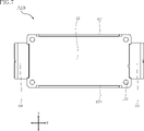
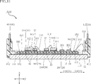
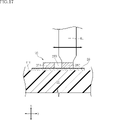
- FIG. 1 is a perspective view of a semiconductor device according to a first embodiment of the present disclosure
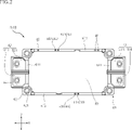
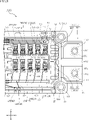
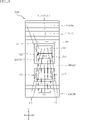
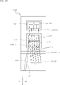
- FIG. 2 is a plan view of the semiconductor device shown in FIG. 1.
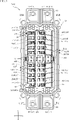
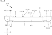
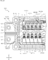
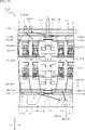
- FIG. 3 is a plan view corresponding to FIG. 2, with the top plate seen through. 4 is a front view of the semiconductor device shown in FIG. 1.
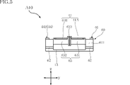
- FIG. 5 is a right side view of the semiconductor device shown in FIG. 1.
- FIG. 6 is a left side view of the semiconductor device shown in FIG. 1.
- FIG. 7 is a bottom view of the semiconductor device shown in FIG. 1.
- FIG. 8 is a partially enlarged view on one side in the first direction of FIG. 3.
- FIG. 9 is a partially enlarged view on the other side in the first direction of FIG. 3.
- FIG. 10 is a partially enlarged view of the central portion of FIG. 3.
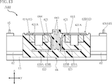
- FIG. 11 is a cross-sectional view taken along line XI-XI of FIG. 3.
- FIG. 12 is a cross-sectional view along line XII-XII in FIG. 3.
- FIG. 13 is a cross-sectional view along line XIII-XIII in FIG. 14 is a partially enlarged view of FIG. 10.
- FIG. 15 is a partially enlarged view of FIG. 14 on one side in the first direction.
- 16 is a partially enlarged view on the other side in the first direction of FIG. 14.
- FIG. 17A and 17B are cross-sectional views for explaining a joining method of the relay terminals shown in FIG.
- FIG. 18 is a partially enlarged view of the first semiconductor element shown in FIG. 8 and its periphery.
- FIG. 19 is a partially enlarged view of the second semiconductor element shown in FIG. 8 and its periphery.
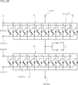
- FIG. 20 is a circuit diagram of the semiconductor device shown in FIG. 21 is a partially enlarged plan view of a first modification of the semiconductor device shown in FIG. 1.
- FIG. 22 is a partially enlarged plan view of a second modification of the semiconductor device shown in FIG. 1.
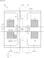
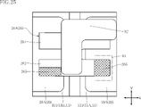
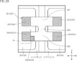
- FIG. 23 is a partially enlarged plan view of a semiconductor device according to a second embodiment of the present disclosure;
- FIG. 24 is a partially enlarged plan view for explaining the manufacturing process of the semiconductor device shown in FIG. 23.
- FIG. 25 is a partially enlarged plan view for explaining the manufacturing process of the semiconductor device shown in FIG. 23.
- FIG. 26 is a partially enlarged plan view for explaining the manufacturing process of the semiconductor device shown in FIG. 23.
- FIG. 27 is a partially enlarged plan view for explaining the manufacturing process of the semiconductor device shown in FIG. 23.
- FIG. 28 is a partially enlarged plan view for explaining the manufacturing process
- FIG. 1 A semiconductor device A10 according to the first embodiment of the present disclosure will be described based on FIGS. 1 to 19.
- FIG. The semiconductor device A10 includes a plurality of substrates 11, a plurality of conductive members 20, a plurality of input terminals 41, an output terminal 42, a plurality of relay terminals 26, and a plurality of semiconductor elements 31.
- FIG. The semiconductor device A10 further includes a plurality of gate wirings 24, a plurality of detection wirings 25, a plurality of gate terminals 43, a plurality of detection terminals 44, a plurality of diodes 32, a heat dissipation member 13, and a case 60.
- FIGS. 3 and 8 to 11 are transparent through the top plate 69 for convenience of understanding.
- the XI-XI line is indicated by a dashed line.
- the semiconductor device A10 shown in FIG. 1 is a power module.
- the semiconductor device A10 is used for inverters such as various electric appliances and hybrid vehicles.
- the semiconductor device A10 has a rectangular shape (or a substantially rectangular shape) when viewed in the thickness direction z.
- a thickness direction z refers to a direction along the thickness of the plurality of first conductive members 20A.
- the direction orthogonal to the thickness direction z is called the first direction x.
- a direction orthogonal to both the thickness direction z and the first direction x is called a second direction y.
- the first direction x is the longitudinal direction of the semiconductor device A10.
- the plurality of base materials 11 are electrically insulating members supported by heat radiating members 13, as shown in FIG.
- the plurality of bases 11 includes two bases 11 adjacent to each other in the first direction x.
- the two substrates 11 are called a first substrate 11A and a second substrate 11B.
- the number of substrates 11 may be plural as in the semiconductor device A10, or may be singular.
- the first base material 11A and the second base material 11B have a principal surface 111 and a back surface 112 facing opposite to each other in the thickness direction z. As shown in FIG. 10, a gap S is provided between the first base material 11A and the second base material 11B.
- the plurality of base materials 11 are made of a material containing ceramics with excellent thermal conductivity. Examples of such ceramics include aluminum nitride (AlN).
- a DBC (Direct Bonded Copper) substrate may be used as the plurality of substrates 11 .
- the DBC substrate is obtained by directly bonding a copper (Cu) foil to a substrate containing aluminum nitride on both sides of the substrate in the thickness direction z.
- Each of the plurality of conductive members 20 is arranged on one of the main surfaces 111 of the plurality of base materials 11, as shown in FIG.
- the plurality of conductive members 20 includes a plurality of first conductive members 20A, a plurality of second conductive members 20B and a plurality of third conductive members 20C.
- the composition of the plurality of conductive members 20 includes copper.
- the plurality of conductive members 20 can be easily obtained by patterning the copper foil bonded to the main surface 111 .
- the surfaces of the plurality of conductive members 20 may be plated with silver (Ag).
- the multiple first conductive members 20A include two first conductive members 20A adjacent to each other in the first direction x.
- 20 A of several 1st electric conduction members are individually arrange
- the plurality of second conductive members 20B includes two second conductive members 20B adjacent to each other in the first direction x, and is positioned next to the plurality of first conductive members 20A in the second direction y.
- the plurality of second conductive members 20B are individually arranged on the major surfaces 111 of the plurality of base materials 11 .
- the plurality of third conductive members 20C includes two third conductive members 20C adjacent to each other in the first direction x, and a plurality of first conductive members 20C sandwiching the plurality of second conductive members 20B in the second direction y. It is located on the side opposite to member 20A.
- the multiple third conductive members 20 ⁇ /b>C are individually arranged on the major surfaces 111 of the multiple base materials 11 .
- the plurality of gate wirings 24 are arranged on the main surfaces 111 of the plurality of substrates 11, as shown in FIG.
- the plurality of gate wirings 24 includes a plurality of first gate wirings 24A and a plurality of second gate wirings 24B.
- the plurality of first gate wirings 24A are individually arranged on the plurality of substrates 11 and are adjacent to each other in the first direction x.
- the plurality of first gate lines 24A are adjacent to the plurality of first conductive members 20A in the second direction y.
- the plurality of second gate wirings 24B are individually arranged on the plurality of substrates 11 and are adjacent to each other in the first direction x.
- the multiple second gate lines 24B are close to the multiple third conductive members 20C in the second direction y.
- the plurality of detection wirings 25 are arranged on the main surfaces 111 of the plurality of base materials 11, as shown in FIG.
- the plurality of detection wirings 25 includes a plurality of first detection wirings 25A and a plurality of second detection wirings 25B.
- the plurality of first detection wirings 25A are individually arranged on the plurality of substrates 11 and are adjacent to each other in the first direction x.
- the plurality of first detection wirings 25A are positioned between the plurality of first conductive members 20A and the plurality of first gate wirings 24A in the second direction y.
- the plurality of second detection wirings 25B are individually arranged on the plurality of substrates 11 and are adjacent to each other in the first direction x.
- the plurality of second detection wirings 25B are positioned between the plurality of third conductive members 20C and the plurality of second gate wirings 24B in the second direction y.
- Each of the plurality of relay terminals 26 is joined to two conductive members 20 adjacent to each other in the first direction x among the plurality of conductive members 20, as shown in FIGS.
- the plurality of relay terminals 26 have a flat plate shape orthogonal to the thickness direction z.
- the plurality of relay terminals 26 are made of metal plates.
- the composition of the metal plate contains copper.
- Each of the plurality of relay terminals 26 has a thickness of, for example, 0.3 mm or more and 0.5 mm or less. Therefore, the thickness of each of the plurality of relay terminals 26 is thinner than the thickness of each of the plurality of input terminals 41 and output terminals 42 . Furthermore, each of the plurality of relay terminals 26 is thicker than each of the plurality of conductive members 20 .
- the multiple relay terminals 26 include a first relay terminal 26A, a second relay terminal 26B and a third relay terminal 26C.
- the shapes of the second relay terminal 26B and the third relay terminal 26C are the same as the shape of the first relay terminal 26A.
- the first relay terminal 26A is joined to the plurality of first conductive members 20A across the gap S. Thereby, the plurality of first conductive members 20A are electrically connected to each other.
- the second relay terminal 26B straddles the gap S and is joined to the plurality of second conductive members 20B. Thereby, the plurality of second conductive members 20B are electrically connected to each other.
- the third relay terminal 26C is joined to the plurality of third conductive members 20C across the gap S. Thereby, the plurality of third conductive members 20C are electrically connected to each other.
- the first relay terminal 26A, the second relay terminal 26B and the third relay terminal 26C are arranged along the second direction y.
- each of the plurality of relay terminals 26 has a first belt-shaped portion 261, a second belt-shaped portion 262 and a connecting portion 263.
- FIG. 14 shows the first relay terminal 26A among the plurality of relay terminals 26, the configurations of the second relay terminal 26B and the third relay terminal 26C are the same as the configuration of the first relay terminal 26A. Therefore, the specific configuration of the plurality of relay terminals 26 will be described with reference to the first relay terminal 26A among the plurality of relay terminals 26.
- FIG. 14 shows the first relay terminal 26A among the plurality of relay terminals 26
- the configurations of the second relay terminal 26B and the third relay terminal 26C are the same as the configuration of the first relay terminal 26A. Therefore, the specific configuration of the plurality of relay terminals 26 will be described with reference to the first relay terminal 26A among the plurality of relay terminals 26.
- the first band-shaped portion 261 and the second band-shaped portion 262 are connected to two conductive members 20 (plurality of first conductive members 20A) among the plurality of conductive members 20 that are adjacent to each other in the first direction x. are spliced.
- the first strip-shaped portion 261 and the second strip-shaped portion 262 extend in the first direction x and are adjacent to each other in the second direction y.
- the connecting portion 263 connects the first belt-shaped portion 261 and the second belt-shaped portion 262 .
- the connecting portion 263 is positioned between the first strip portion 261 and the second strip portion 262 in the second direction y.
- the first band-shaped portion 261 has a first side 261A and a third side 261B.
- the first side 261A and the third side 261B extend in the first direction x.
- the third side 261B is located on the opposite side of the first side 261A with the connecting portion 263 interposed therebetween in the first direction x.
- the second band-shaped portion 262 has a second side 262A and a fourth side 262B.
- the second side 262A and the fourth side 262B extend in the first direction x.
- the fourth side 262B is located on the opposite side of the second side 262A with the connecting portion 263 interposed therebetween in the first direction x.
- the second side 262A faces the first side 261A of the first band-shaped portion 261 in the second direction y.
- the fourth side 262B faces the third side 261B of the first band-shaped portion 261 in the second direction y.
- the connecting portion 263 has a first intermediate side 263A, a first connecting side 263B and a second connecting side 263C.
- the first intermediate side 263A extends in the second direction y.
- the first connecting side 263B connects the first intermediate side 263A and the first side 261A of the first belt-shaped portion 261 .
- the second connecting side 263 ⁇ /b>C connects the first intermediate side 263 ⁇ /b>A and the second side 262 ⁇ /b>A of the second belt-shaped portion 262 .
- the connecting portion 263 has a second intermediate side 263D, a third connecting side 263E and a fourth connecting side 263F.
- the second intermediate side 263D extends in the second direction y.
- the second intermediate side 263D is located on the opposite side of the first intermediate side 263A in the first direction x.
- the third connecting side 263E connects the second intermediate side 263D and the third side 261B of the first band-shaped portion 261.
- the fourth connecting side 263 ⁇ /b>F connects the second intermediate side 263 ⁇ /b>D and the fourth side 262 ⁇ /b>B of the second band-shaped portion 262 .
- a first virtual line 267A, a second virtual line 267B, a third virtual line 267C and a fourth virtual line 267D are set.
- the first virtual line 267A extends in the first direction x and overlaps the first side 261A and the third side 261B of the first band-shaped portion 261 when viewed in the thickness direction z.
- the second virtual line 267B extends in the second direction y and overlaps the first intermediate side 263A of the connecting portion 263 when viewed in the thickness direction z.
- the third imaginary line 267C extends in the first direction x and overlaps the second side 262A and the fourth side 262B of the second band-shaped portion 262 when viewed in the thickness direction z.
- the fourth virtual line 267D extends in the second direction y and overlaps the second intermediate side 263D of the connecting portion 263 when viewed in the thickness direction z.
- the first connecting side 263B of the connecting portion 263 is located away from the first imaginary intersection 268A when viewed in the thickness direction z.
- the first virtual intersection 268A is the intersection of the first virtual line 267A and the second virtual line 267B.
- the second connecting side 263C of the connecting portion 263 is located away from the second imaginary intersection 268B.
- the second virtual intersection point 268B is the intersection point between the second virtual line 267B and the third virtual line 267C.
- the third connecting side 263E of the connecting portion 263 when viewed in the thickness direction z, is located apart from the third imaginary intersection 268C.
- a third virtual intersection point 268C is an intersection point between the first virtual line 267A and the fourth virtual line 267D.
- the fourth connecting side 263F of the connecting portion 263 is located away from the fourth imaginary intersection 268D.
- a fourth virtual intersection point 268D is an intersection point between the third virtual line 267C and the fourth virtual line 267D.
- the first connecting side 263B, the second connecting side 263C, the third connecting side 263E, and the fourth connecting side 263F of the connecting portion 263 extend in the thickness direction z. When viewed, it forms a curved line recessed inwardly of the first relay terminal 26A. When viewed in the thickness direction z, a portion of the connecting portion 263 is surrounded by the first connecting side 263B, the first virtual line 267A and the second virtual line 267B.
- the first band-shaped portion 261 and the second band-shaped portion 262 of each of the plurality of relay terminals 26 are applied to two conductive members 20 adjacent to each other in the first direction x among the plurality of conductive members 20 by the ultrasonic vibration shown in FIG. spliced.
- one side of the first strip-shaped portion 261 and the second strip-shaped portion 262 in the first direction x is in contact with one of the two conductive members 20 adjacent in the first direction x.
- the capillary 81 applies a compressive load in the thickness direction z to each end of the first strip portion 261 and the second strip portion 262 overlapping the conductive member 20 in the thickness direction z.
- ultrasonic vibration is generated in the capillary 81 along the second direction y.
- the frequency of the ultrasonic vibration is, for example, 20 kHz or more and 60 kHz or less.
- the ends of each of the first band-shaped portion 261 and the second band-shaped portion 262 are joined to one of the plurality of conductive members 20 .
- the plurality of teeth provided in each of the internal connection portions 412 of the plurality of input terminals 41 and the internal connection portions 422 of the output terminals 42 described above also undergo ultrasonic vibration along the second direction y shown in FIG. can be bonded to the object by providing the plurality of teeth with a .
- the semiconductor device A10 includes a plurality of first conduction members 27A.
- the plurality of first conductive members 27A are joined to the plurality of gate wirings 24 so as to straddle the gap S.
- the plurality of first gate wirings 24A are electrically connected to each other
- the plurality of second gate wirings 24B are electrically connected to each other.
- each of the plurality of first conduction members 27A is composed of a plurality of wires.
- the plurality of wires are, for example, aluminum (Al). 27 A of several 1st conduction members are along the 1st direction x.
- the semiconductor device A10 includes a plurality of second conduction members 27B.
- the plurality of second conduction members 27B are joined to the plurality of detection wirings 25 so as to straddle the gap S.
- the plurality of first detection wirings 25A are electrically connected to each other
- the plurality of second detection wirings 25B are electrically connected to each other.
- each of the plurality of second conduction members 27B is composed of a plurality of metal wires.
- the plurality of wires are, for example, aluminum.
- the plurality of second conductive members 27B are along the first direction x.
- the semiconductor device A10 has a pair of pads 28. As shown in FIG. 8, the semiconductor device A10 has a pair of pads 28. As shown in FIG. The pair of pads 28 are adjacent to each other in the first direction x. A pair of pads 28 are positioned at the corners of the first base material 11A. The pair of pads 28 are close to the first conductive member 20A joined to the first base material 11A among the plurality of first conductive members 20A.
- the plurality of input terminals 41 are part of the external connection terminals provided on the semiconductor device A10, as shown in FIGS.
- a plurality of input terminals 41 are connected to a DC power supply arranged outside the semiconductor device A10.
- a plurality of input terminals 41 are supported by the case 60 .
- the plurality of input terminals 41 are made of metal plates.
- the metal plate contains, for example, copper.
- the thickness of the plurality of input terminals 41 is 1.0 mm.
- the multiple input terminals 41 include a first input terminal 41A and a second input terminal 41B.
- the first input terminal 41A is a positive electrode (P terminal).
- the first input terminal 41A is joined to the first pad portion 21 of the first conductive member 20A arranged on the first base material 11A among the plurality of first conductive members 20A. Thereby, the first input terminal 41A is electrically connected to the plurality of first conductive members 20A.
- the second input terminal 41B is a negative electrode (N terminal).
- the second input terminal 41B is joined to the third pad portion 23 of the third conductive member 20C arranged on the first base material 11A among the plurality of third conductive members 20C. Thereby, the second input terminal 41B is electrically connected to the plurality of third conductive members 20C.
- the first input terminal 41A and the second input terminal 41B are adjacent to each other in the second direction y.
- each of the first input terminal 41A and the second input terminal 41B has an external connection portion 411, an internal connection portion 412 and an intermediate portion 413.
- the external connection part 411 has a flat plate shape exposed from the semiconductor device A10 and perpendicular to the thickness direction z.
- a DC power supply cable or the like is connected to the external connection portion 411 .
- the external connection portion 411 is supported by the case 60 .
- the external connection portion 411 is provided with a connection hole 411A penetrating in the thickness direction z.
- a fastening member such as a bolt is inserted into the connection hole 411A.
- the surface of the external connection portion 411 may be plated with nickel (Ni).
- the internal connection portion 412 is joined to the first pad portion 21 of the first conductive member 20A at the first input terminal 41A, and is joined to the third pad portion 23 of the third conductive member 20C at the second input terminal 41B. shape.
- the internal connection portion 412 has three teeth, and these multiple teeth are arranged along the second direction y. A plurality of teeth are bent in the thickness direction z. Therefore, the plurality of teeth are hook-shaped when viewed in the second direction y. All of the teeth are joined to the first pad portion 21 and the third pad portion 23 by ultrasonic vibration.
- the intermediate portion 413 interconnects the external connection portion 411 and the internal connection portion 412 .
- the intermediate portion 413 has an L-shaped cross section with respect to the first direction x.
- Intermediate portion 413 has base portion 413A and standing portion 413B.
- the base 413A extends along the first direction x and the second direction y.
- One end of the base portion 413A in the first direction x is connected to the internal connection portion 412 .
- the standing portion 413B stands up from the base portion 413A in the thickness direction z.
- One end of the upright portion 413B in the thickness direction z is connected to the external connection portion 411 .
- the output terminals 42 are part of the external connection terminals provided on the semiconductor device A10, as shown in FIGS.
- the output terminal 42 is connected to a power supply object (such as a motor) arranged outside the semiconductor device A10.
- the output terminal 42 is supported by the case 60 and positioned on the opposite side of the plurality of bases 11 from the plurality of input terminals 41 in the first direction x.
- the output terminal 42 is made of a metal plate.
- the metal plate contains, for example, copper.
- the thickness of the output terminal 42 is 1.0 mm.
- the output terminal 42 is separated into two, a first terminal portion 42A and a second terminal portion 42B.
- the output terminal 42 may be a single member in which the first terminal portion 42A and the second terminal portion 42B are integrated.
- the first terminal portion 42A and the second terminal portion 42B are joined to the second pad portion 22 of the second conductive member 20B arranged on the second base material 11B among the plurality of second conductive members 20B.
- the output terminal 42 is electrically connected to the plurality of second conductive members 20B.
- the first terminal portion 42A and the second terminal portion 42B are adjacent to each other in the second direction y.
- each of the first terminal portion 42A and the second terminal portion 42B has an external connection portion 421, an internal connection portion 422 and an intermediate portion 423.
- the external connection part 421 has a flat plate shape exposed from the semiconductor device A10 and orthogonal to the thickness direction z. A cable or the like that conducts to a power supply target is joined to the external connection portion 421 .
- the external connection portion 421 is supported by the case 60 .
- the external connection portion 421 is provided with a connection hole 421A penetrating in the thickness direction z. A fastening member such as a bolt is inserted into the connection hole 421A.
- the surface of the external connection portion 411 may be plated with nickel.
- the internal connection part 422 has a comb shape joined to the second pad part 22 of the second conductive member 20B.
- the internal connection portion 412 has three teeth, and these multiple teeth are arranged along the second direction y.
- a plurality of teeth are bent in the thickness direction z. Therefore, the plurality of teeth are hook-shaped when viewed in the second direction y. All of the teeth are joined to the second pad portion 22 by ultrasonic vibration.
- the intermediate portion 423 interconnects the external connection portion 421 and the internal connection portion 422 .
- the intermediate portion 423 has an L-shaped cross section with respect to the first direction x.
- the intermediate portion 423 has a base portion 423A and an upright portion 423B.
- the base 423A extends along the first direction x and the second direction y.
- One end of the base portion 423A in the first direction x is connected to the internal connection portion 422 .
- the standing portion 423B stands up from the base portion 423A in the thickness direction z.
- One end of the upright portion 423B in the thickness direction z is connected to the external connection portion 421 .
- the plurality of gate terminals 43 are part of the external connection terminals provided on the semiconductor device A10, as shown in FIGS.
- the multiple gate terminals 43 are electrically connected to the multiple gate wirings 24 .
- the plurality of gate terminals 43 are connected to a driving circuit (eg, gate driver) of the semiconductor device A10 arranged outside.
- a plurality of gate terminals 43 are supported by the case 60 .
- the plurality of gate terminals 43 are composed of metal rods.
- the metal rod contains, for example, copper.
- the surfaces of the plurality of gate terminals 43 may be plated with tin (Sn) or nickel and tin.
- the plurality of gate terminals 43 has an L-shaped cross section with respect to the first direction x. A part of each of the plurality of gate terminals 43 protrudes from the case 60 toward the main surfaces 111 of the plurality of substrates 11 in the thickness direction z.
- the multiple gate terminals 43 include a first gate terminal 43A and a second gate terminal 43B. As shown in FIG. 10, the first gate terminal 43A is close to the plurality of first gate wirings 24A in the second direction y. As shown in FIG. 10, the second gate terminal 43B is located on the opposite side of the plurality of substrates 11 from the first gate terminal 43A in the second direction y. The second gate terminal 43B is close to the plurality of second gate wirings 24B.
- the plurality of detection terminals 44 are part of the external connection terminals provided on the semiconductor device A10, as shown in FIGS.
- the multiple detection terminals 44 are electrically connected to the multiple detection wirings 25 .
- a plurality of detection terminals 44 are connected to a control circuit of the semiconductor device A10 arranged outside.
- the multiple detection terminals 44 are supported by the case 60 .
- the plurality of detection terminals 44 are composed of metal rods.
- the metal rod contains, for example, copper. Note that the surfaces of the plurality of detection terminals 44 may be tinned, or nickel-plated and tin-plated.
- the plurality of detection terminals 44 has an L-shaped cross section with respect to the first direction x. A part of each of the plurality of detection terminals 44 protrudes from the case 60 toward the main surface 111 of the plurality of substrates 11 in the thickness direction z.
- the multiple detection terminals 44 include a first detection terminal 44A and a second detection terminal 44B.
- the first detection terminal 44A is located next to the first gate terminal 43A in the first direction x, as shown in FIG.
- the second detection terminal 44B is located next to the second gate terminal 43B in the first direction x, as shown in FIG.
- the semiconductor device A10 has an input current detection terminal 45.
- FIG. The input current detection terminal 45 is part of the external connection terminals provided on the semiconductor device A10.
- the input current detection terminal 45 is connected to the control circuit of the semiconductor device A10 arranged outside.
- Input current detection terminal 45 is supported by case 60 .
- the input current detection terminal 45 is composed of a metal rod.
- the metal rod contains, for example, copper.
- the surface of the input current detection terminal 45 may be tin-plated, or nickel-plated and tin-plated.
- the shape of the input current detection terminal 45 is the same as that of the plurality of gate terminals 43 shown in FIG.
- a portion of the input current detection terminal 45 protrudes from the case 60 toward the main surface 111 of the plurality of substrates 11 in the thickness direction z, like the plurality of gate terminals 43 shown in FIG. In the second direction y, the position of the input current detection terminal 45 is the same as the position of the first gate terminal 43A.
- the input current detection terminal 45 is located away from the first gate terminal 43A on the side where the output terminal 42 is located in the first direction x.
- the semiconductor device A10 includes an input current detection wire 54. As shown in FIG. The input current detection wire 54 is joined to the input current detection terminal 45 and one of the plurality of first conductive members 20A. In the semiconductor device A10, one end of the input current detection wire 54 is joined to the first conductive member 20A among the plurality of first conductive members 20A arranged on the second base material 11B. Accordingly, the input current detection terminal 45 is electrically connected to the plurality of first conductive members 20A. Input current sensing wire 54 is, for example, aluminum.
- the semiconductor device A10 has a pair of thermistor terminals 46.
- a pair of thermistor terminals 46 are part of the external connection terminals provided on the semiconductor device A10.
- a pair of thermistor terminals 46 are connected to a control circuit of the semiconductor device A10 arranged outside.
- a pair of thermistor terminals 46 are supported by a case 60 .
- a pair of thermistor terminals 46 are composed of metal rods.
- the metal rod contains, for example, copper.
- the surfaces of the pair of thermistor terminals 46 may be tin-plated, or nickel-plated and tin-plated.
- the shape of the pair of thermistor terminals 46 is the same as that of the plurality of gate terminals 43 shown in FIG. A part of the pair of thermistor terminals 46 protrudes from the case 60 toward the main surface 111 of the plurality of substrates 11 in the thickness direction z, like the plurality of gate terminals 43 shown in FIG. In the second direction y, the position of the pair of thermistor terminals 46 is the same as the position of the first gate terminal 43A.
- the pair of thermistor terminals 46 are located away from the first gate terminal 43A in the first direction x on the side where the plurality of input terminals 41 are located.
- a pair of thermistor terminals 46 are adjacent to each other in the first direction x.
- the semiconductor device A10 includes a pair of thermistor wires 55. As shown in FIG. A pair of thermistor wires 55 are individually joined to a pair of thermistor terminals 46 and a pair of pads 28 . As a result, the pair of input current detection terminals 45 are electrically connected to the pair of pads 28 .
- a pair of thermistor wires 55 are made of aluminum, for example.
- the plurality of semiconductor elements 31 are joined to the plurality of first conductive members 20A and the plurality of second conductive members 20B.
- the multiple semiconductor elements 31 include multiple first semiconductor elements 31A and multiple second semiconductor elements 31B.
- the plurality of first semiconductor elements 31A are joined to the plurality of first conductive members 20A and arranged along the first direction x.
- the plurality of second semiconductor elements 31B are joined to the plurality of second conductive members 20B and arranged along the first direction x.
- the plurality of semiconductor elements 31 are IGBTs (Insulated Gate Bipolar Transistors) whose main component is silicon (Si) or silicon carbide (SiC).
- the plurality of semiconductor elements 31 may be MOSFETs (Metal-Oxide-Semiconductor Field-Effect Transistors). In the description of the semiconductor device A10, the case where the plurality of semiconductor elements 31 are IGBTs is targeted.
- the plurality of semiconductor elements 31 have first electrodes 311, second electrodes 312 and gate electrodes 313. As shown in FIGS. 11, 18 and 19, the plurality of semiconductor elements 31 have first electrodes 311, second electrodes 312 and gate electrodes 313. As shown in FIGS. 11, 18 and 19, the plurality of semiconductor elements 31 have first electrodes 311, second electrodes 312 and gate electrodes 313. As shown in FIGS. 11, 18 and 19, the plurality of semiconductor elements 31 have first electrodes 311, second electrodes 312 and gate electrodes 313. As shown in FIGS.
- the first electrode 311 is provided at the upper end of the semiconductor element 31 located on the side facing the main surfaces 111 of the plurality of base materials 11 in the thickness direction z.
- An emitter current flows from the inside of the semiconductor element 31 to the first electrode 311 .
- the first electrode 311 includes a pair of regions adjacent in the second direction y.
- the second electrode 312 is provided at the lower end of the semiconductor element 31 located on the side opposite to the main surface 111 of the plurality of substrates 11 in the thickness direction z.
- a collector current flows through the second electrode 312 toward the inside of the semiconductor element 31 .
- the second electrode 312 is joined to one of the multiple first conductive members 20A and the multiple second conductive members 20B via the conductive bonding layer 39 . Thereby, the second electrodes 312 of the plurality of first semiconductor elements 31A are electrically connected to the plurality of first conductive members 20A. The second electrodes 312 of the plurality of second semiconductor elements 31B are electrically connected to the plurality of second conductive members 20B.
- the conductive bonding layer 39 is lead-free solder or the like containing tin as a main component.
- the gate electrode 313 is provided at the upper end of the semiconductor element 31 located on the side facing the main surfaces 111 of the plurality of substrates 11 in the thickness direction z.
- the gate electrode 313 is sandwiched between a pair of regions of the first electrode 311.
- a gate voltage for driving the semiconductor element 31 is applied to the gate electrode 313 .
- the area of the gate electrode 313 is smaller than the area of the first electrode 311 when viewed in the thickness direction z.
- the plurality of diodes 32 are joined to the plurality of first conductive members 20A and the plurality of second conductive members 20B, as shown in FIG.
- the number of diodes 32 corresponds to the number of semiconductor elements 31 .
- a plurality of diodes 32 are individually conducted to a plurality of semiconductor elements 31 .
- the plurality of diodes 32 are Schottky barrier diodes.
- the multiple diodes 32 have anode electrodes 321 and cathode electrodes 322 .
- the anode electrode 321 is provided at the upper end of the diode 32 located on the side facing the main surfaces 111 of the plurality of base materials 11 in the thickness direction z.
- the cathode electrode 322 is provided at the lower end of the diode 32 located on the side opposite to the main surface 111 of the plurality of substrates 11 in the thickness direction z.
- the cathode electrode 322 is joined to either one of the multiple first conductive members 20A and the multiple second conductive members 20B via the conductive bonding layer 39 . Thereby, each of the cathode electrodes 322 of the plurality of diodes 32 is electrically connected to one of the plurality of first conductive members 20A and the plurality of second conductive members 20B.
- the semiconductor device A10 includes a thermistor 33, as shown in FIGS.
- the thermistor 33 is electrically connected to the pair of pads 28 .
- the thermistor 33 is an NTC (Negative Temperature Coefficient) thermistor.
- An NTC thermistor has a characteristic that its resistance gradually decreases with temperature rise.
- the thermistor 33 is used as a temperature detection sensor for the semiconductor device A10.
- the thermistor 33 is electrically connected to a pair of thermistor terminals 46 via a pair of pads 28 and a pair of thermistor wires 55 .
- the semiconductor device A10 includes a plurality of first wires 511 to a plurality of sixth wires 516, a plurality of first gate wires 521 and a plurality of first detection wires 531, as shown in FIGS. These wires are individually bonded to a plurality of semiconductor elements 31 and a plurality of diodes 32 .
- the composition of these wires includes, for example, aluminum.
- the plurality of first wires 511 are individually joined to the plurality of first electrodes 311 of the plurality of first semiconductor elements 31A and the plurality of first conductive members 20A.
- the multiple second wires 512 are individually joined to the multiple anode electrodes 321 of the diodes 32 and the multiple second conductive members 20B.
- the first electrodes 311 of the plurality of first semiconductor elements 31A and the anode electrodes 321 of the plurality of diodes 32 individually corresponding thereto are electrically connected to the plurality of second conductive members 20B.
- the plurality of third wires 513 are joined to the first electrodes 311 of the plurality of first semiconductor elements 31A and the anode electrodes 321 of the plurality of diodes 32 individually corresponding thereto. Thereby, the anode electrodes 321 of the plurality of diodes 32 joined to the plurality of first conductive members 20A are individually connected to the first electrodes 311 of the plurality of first semiconductor elements 31A.
- the plurality of first gate wires 521 and the plurality of first detection wires 531 individually joined to the plurality of first semiconductor elements 31A will be described with reference to FIG.
- the plurality of first gate wires 521 are individually joined to the gate electrodes 313 of the plurality of first semiconductor elements 31A and the plurality of first gate wirings 24A.
- the plurality of first detection wires 531 are individually joined to the plurality of first electrodes 311 of the first semiconductor elements 31A and the plurality of first detection wirings 25A.
- the plurality of fourth wires 514 are individually joined to one region of the first electrodes 311 of the plurality of second semiconductor elements 31B and the plurality of third conductive members 20C.
- the plurality of fifth wires 515 are individually joined to the other regions of the first electrodes 311 of the plurality of second semiconductor elements 31B and the plurality of third conductive members 20C. Thereby, the first electrodes 311 of the plurality of second semiconductor elements 31B are electrically connected to the plurality of third conductive members 20C.
- the plurality of sixth wires 516 are individually joined to the other regions of the first electrodes 311 of the plurality of second semiconductor elements 31B and the anode electrodes 321 of the plurality of diodes 32 .
- the anode electrodes 321 of the plurality of diodes 32 joined to the plurality of second conductive members 20B are individually connected to the first electrodes 311 of the plurality of second semiconductor elements 31B, and the plurality of fifth wires 515 to the plurality of third conductive members 20C.
- the first electrodes 311 of the plurality of second semiconductor elements 31B are electrically connected to the plurality of third conductive members 20C via the plurality of fourth wires 514 and the plurality of fifth wires 515.
- the second input terminal 41B is electrically connected to the first electrodes 311 of the plurality of second semiconductor elements 31B.
- the plurality of first gate wires 521 and the plurality of first detection wires 531 individually joined to the plurality of second semiconductor elements 31B will be described with reference to FIGS. 8 and 19.
- FIG. The plurality of first gate wires 521 are individually joined to the plurality of gate electrodes 313 of the second semiconductor elements 31B and the plurality of second gate wirings 24B.
- the plurality of first detection wires 531 are individually joined to the plurality of first electrodes 311 of the second semiconductor elements 31B and the plurality of second detection wirings 25B.
- the semiconductor device A10 includes a pair of second gate wires 522, as shown in FIG. A pair of second gate wires 522 are joined to the plurality of gate terminals 43 and the plurality of gate wirings 24 .
- the plurality of second gate wires 522 are made of aluminum, for example.
- one second gate wire 522 is joined to the first gate terminal 43A and the first gate wiring 24A among the plurality of first gate wirings 24A arranged on the first substrate 11A.
- the first gate terminal 43A is electrically connected to the gate electrodes 313 of the plurality of first semiconductor elements 31A.
- the other second gate wire 522 is joined to the second gate terminal 43B and the second gate wiring 24B among the plurality of second gate wirings 24B arranged on the second substrate 11B.
- the second gate terminal 43B is electrically connected to the gate electrodes 313 of the plurality of second semiconductor elements 31B.
- the semiconductor device A10 includes a pair of second detection wires 532, as shown in FIG. A pair of second detection wires 532 are joined to the plurality of detection terminals 44 and the plurality of detection wirings 25 .
- the multiple second detection wires 532 are, for example, aluminum.
- one second detection wire 532 is joined to the first detection terminal 44A and the first detection wiring 25A among the plurality of first detection wirings 25A arranged on the second substrate 11B.
- the first detection terminals 44A are electrically connected to the first electrodes 311 of the plurality of first semiconductor elements 31A.
- the other second detection wire 532 is joined to the second detection terminal 44B and the second detection wiring 25B arranged on the first substrate 11A among the plurality of second detection wirings 25B.
- the second detection terminals 44B are electrically connected to the first electrodes 311 of the plurality of second semiconductor elements 31B.
- the heat dissipation member 13 is joined to the back surface 112 of the first base material 11A and the back surface 112 of the second base material 11B. Thereby, the first base material 11A and the second base material 11B are supported by the heat dissipation member 13 .
- the heat dissipation member 13 is composed of a flat metal plate.
- the metal is, for example, copper.
- the surface of the heat dissipation member 13 may be plated with nickel.
- a cooling member different from the heat dissipation member 13 may be attached to the portion of the heat dissipation member 13 exposed from the semiconductor device A10. As shown in FIGS.
- a plurality of support holes 131 are provided at four corners of the heat radiating member 13 when viewed in the thickness direction z.
- the plurality of support holes 131 penetrate the heat radiating member 13 in the thickness direction z.
- the plurality of support holes 131 are used to support the heat dissipation member 13 supporting the first base material 11A and the second base material 11B in the case 60 .
- the heat transfer member 12 is arranged on the back surface 112 of the first base material 11A and the back surface 112 of the second base material 11B.
- the heat transfer member 12 is made of a metal material such as copper foil.
- the heat transfer member 12 conducts heat generated from the plurality of semiconductor elements 31 to the heat dissipation member 13 .
- the adhesive layer 19 is interposed between the heat radiating member 13 and the heat transfer member 12, as shown in FIG.
- the adhesive layer 19 is used to bond the heat dissipation member 13 to both the first base material 11A and the second base material 11B.
- the adhesive layer 19 is lead-free solder or the like containing tin as a main component.
- the heat dissipation member 13 is joined to both the first base material 11A and the second base material 11B via the heat transfer member 12 and the adhesive layer 19 .
- the case 60 is an electrically insulating member surrounding the first base material 11A and the second base material 11B when viewed in the thickness direction z, as shown in FIGS.
- the case 60 is made of a material containing synthetic resin with excellent heat resistance, such as PPS (polyphenylene sulfide).
- the case 60 has a pair of first side walls 611 , a pair of second side walls 612 , a plurality of mounting portions 62 , an input terminal block 63 and an output terminal block 64 .
- the pair of first side walls 611 are separated from each other in the first direction x.
- the pair of first side walls 611 are arranged along both the second direction y and the thickness direction z, and one end in the thickness direction z is in contact with the heat dissipation member 13 .
- the pair of second side walls 612 are separated from each other in the second direction y.
- the pair of second side walls 612 are arranged along both the first direction x and the thickness direction z, and are in contact with the heat dissipation member 13 at one end in the thickness direction z. Both ends of the pair of second side walls 612 in the first direction x are connected to the pair of first side walls 611 .
- a first gate terminal 43A, a first detection terminal 44A, an input current detection terminal 45 and a pair of thermistor terminals 46 are arranged inside one of the second side walls 612 .
- a second gate terminal 43B and a second detection terminal 44B are arranged inside the other second side wall 612 .
- the ends of these terminals that are close to the first base material 11A and the second base material 11B in the thickness direction z are supported by a pair of second side walls 612.
- FIGS. 8 to 10 the ends of these terminals that are close to the first base material 11A and the second base material 11B in
- the plurality of mounting portions 62 are portions provided at the four corners of the case 60 when viewed in the thickness direction z.
- the heat radiating member 13 is in contact with the lower surfaces of the plurality of mounting portions 62 .
- Each of the plurality of mounting portions 62 is provided with a mounting hole 621 penetrating in the thickness direction z.
- the positions of the plurality of mounting holes 621 correspond to the positions of the plurality of support holes 131 of the heat dissipation member 13 .
- the heat radiating member 13 is supported by the case 60 by fitting fastening members such as pins into the plurality of mounting holes 621 and the plurality of support holes 131 .
- the input terminal block 63 protrudes outward in the first direction x from one first side wall 611 .
- a plurality of input terminals 41 are supported on the input terminal block 63 .
- the input terminal block 63 has a first terminal block 631 and a second terminal block 632 .
- the first terminal block 631 and the second terminal block 632 are separated from each other in the second direction y.
- the first terminal block 631 supports the first input terminal 41A.
- the external connection portion 411 of the first input terminal 41A is exposed from the first terminal block 631 .
- the second terminal block 632 supports the second input terminal 41B.
- the external connection portion 411 of the second input terminal 41B is exposed from the second terminal block 632 .
- a plurality of grooves 633 extending in the first direction x are formed between the first terminal block 631 and the second terminal block 632 .
- a pair of nuts 634 are arranged inside the first terminal block 631 and the second terminal block 632 .
- a pair of nuts 634 correspond to a pair of connection holes 411A provided in the first input terminal 41A and the second input terminal 41B. Fastening members such as bolts inserted into the pair of connection holes 411A are fitted to the pair of nuts 634 .
- the output terminal block 64 protrudes outward in the first direction x from the other first side wall 611 .
- the output terminal block 64 supports the output terminal 42 .
- the output terminal block 64 has a first terminal block 641 and a second terminal block 642 .
- the first terminal block 641 and the second terminal block 642 are separated from each other in the second direction y.
- the first terminal block 641 supports the first terminal portion 42A of the output terminal 42 .
- the external connection portion 421 of the first terminal portion 42A is exposed from the first terminal block 641 .
- the second terminal block 642 supports the second terminal portion 42B of the output terminal 42 .
- the external connection portion 421 of the second terminal portion 42B is exposed from the second terminal block 642 .
- a plurality of grooves 643 extending in the first direction x are formed between the first terminal block 641 and the second terminal block 642 .
- a pair of nuts 644 are arranged inside the first terminal block 641 and the second terminal block 642 .
- a pair of nuts 644 correspond to a pair of connection holes 421A provided in the first terminal portion 42A and the second terminal portion 42B. Fastening members such as bolts inserted into the pair of connection holes 421 A are fitted to the pair of nuts 644 .
- the top plate 69 is a member that closes the internal region of the semiconductor device A10 formed by the heat dissipation member 13 and the case 60, as shown in FIG.
- the top plate 69 faces the major surfaces 111 of the plurality of substrates 11 .
- the top plate 69 is supported by a pair of first side walls 611 and a pair of second side walls 612 of the case 60 .
- the top plate 69 is made of a material containing an electrically insulating synthetic resin. Instead of the top plate 69, the internal region of the semiconductor device A10 may be filled with silicone gel or the like.
- the upper arm circuit 71 includes a plurality of first conductive members 20A, a plurality of first semiconductor elements 31A, and a plurality of diodes 32 joined to the plurality of first conductive members 20A.
- the plurality of first semiconductor elements 31A and the plurality of diodes 32 forming the upper arm circuit 71 are connected in parallel between the first input terminal 41A and the output terminal .
- the gate electrodes 313 of the plurality of first semiconductor elements 31A are connected in parallel to the first gate terminal 43A.
- a driving circuit such as a gate driver arranged outside the semiconductor device A10 applies a gate voltage to the first gate terminal 43A, thereby simultaneously driving the plurality of first semiconductor elements 31A.
- the first electrodes 311 of the plurality of first semiconductor elements 31A are connected in parallel to the first detection terminal 44A. Emitter currents flowing through the plurality of first semiconductor elements 31A are input to a control circuit arranged outside the semiconductor device A10 via the first detection terminals 44A.
- the voltage applied to the plurality of first conductive members 20A by the first input terminal 41A and the second input terminal 41B is applied to the externally arranged semiconductor device A10 via the input current detection terminal 45. Input to the control circuit.
- the lower arm circuit 72 is composed of a plurality of second conductive members 20B, a plurality of second semiconductor elements 31B, and a plurality of diodes 32 joined to the plurality of second conductive members 20B.
- the plurality of second semiconductor elements 31B and the plurality of diodes 32 forming the lower arm circuit 72 are connected in parallel between the output terminal 42 and the second input terminal 41B.
- the gate electrodes 313 of the plurality of second semiconductor elements 31B are connected in parallel to the second gate terminal 43B.
- a driving circuit such as a gate driver arranged outside the semiconductor device A10 applies a gate voltage to the second gate terminal 43B, thereby simultaneously driving the plurality of second semiconductor elements 31B.
- the first electrodes 311 of the plurality of second semiconductor elements 31B are connected in parallel to the second detection terminals 44B. Emitter currents flowing through the plurality of second semiconductor elements 31B are input to a control circuit arranged outside the semiconductor device A10 via the second detection terminals 44B.
- a DC voltage is applied to the first input terminal 41A and the second input terminal 41B, and the plurality of semiconductor elements 31 in the upper arm circuit 71 and the lower arm circuit 72 are driven to generate AC voltages of various frequencies from the output terminal 42. is output.
- the AC voltage is supplied to a power supply object such as a motor.
- the semiconductor device A11 differs from the semiconductor device A10 in the configuration of the plurality of relay terminals 26 .
- FIG. 21 shows the first relay terminal 26A among the plurality of relay terminals 26, the configurations of the second relay terminal 26B and the third relay terminal 26C are the same as the configuration of the first relay terminal 26A. Therefore, in the description of the semiconductor device A11 as well, the first relay terminal 26A among the plurality of relay terminals 26 will be described as a representative.
- the first connecting side 263B, the second connecting side 263C, the third connecting side 263E and the fourth connecting side 263F of the connecting portion 263 of the first relay terminal 26A are all form a straight line.
- the first connecting side 263B, the second connecting side 263C, the third connecting side 263E and the fourth connecting side 263F are inclined with respect to the first direction x and the second direction y.
- a portion of the connecting portion 263 is surrounded by the first connecting side 263B, the first virtual line 267A and the second virtual line 267B.
- the semiconductor device A12 differs from the semiconductor device A10 in the configuration of the first relay terminal 26A.
- FIG. 22 shows the first relay terminal 26A among the plurality of relay terminals 26, the configurations of the second relay terminal 26B and the third relay terminal 26C are also the same as the configuration of the first relay terminal 26A. Therefore, in the description of the semiconductor device A12 as well, the first relay terminal 26A among the plurality of relay terminals 26 will be described as a representative.
- the first connecting side 263B, the second connecting side 263C, the third connecting side 263E, and the fourth connecting side 263F of the connecting portion 263 of the first relay terminal 26A have a thickness of When viewed in the direction z, it forms a curved line recessed inwardly of the first relay terminal 26A.
- the first connecting side 263B straddles the first virtual line 267A and the second virtual line 267B.
- the semiconductor device A10 includes relay terminals 26 joined to two conductive members 20 adjacent to each other in the first direction x.
- the relay terminal 26 has a first belt-shaped portion 261 , a second belt-shaped portion 262 and a connecting portion 263 .
- the first band-shaped portion 261 has a first side 261A.
- the connecting portion 263 has a first intermediate side 263A and a first connecting side 263B connecting the first side 261A and the first intermediate side 263A.
- the first connecting side 263B is a first virtual intersection 268A that is the intersection of a first virtual line 267A that overlaps the first side 261A and a second virtual line 267B that overlaps the first intermediate side 263A.
- the concentration of repetitive stress acting on the boundary between one of the first belt-shaped portion 261 and the second belt-shaped portion 262 and the connecting portion 263 affects not only the structure of the relay terminal 26 of the semiconductor device A10 but also the semiconductor devices A11 and A12. can also be reduced by the configuration of each relay terminal 26.
- the thickness of the relay terminal 26 is thicker than the thickness of each of the two conductive members 20 .
- the electrical resistance value of the relay terminal 26 is lowered, so that the internal resistance (parasitic resistance) of the semiconductor device A10 caused by the relay terminal 26 can be reduced.
- the heat conduction of the relay terminal 26 is improved, uneven heat distribution between the two conductive members 20 caused by the heat generated by the semiconductor element 31 is alleviated. As a result, concentration of thermal stress in the two bases 11 on which the two conductive members 20 are individually arranged can be reduced.
- the semiconductor device A10 has a first input terminal 41A electrically connected to two conductive members 20 (a plurality of first electrically conductive members 20A) and a second input terminal electrically connected to a semiconductor element 31 (one of the plurality of second semiconductor elements 31B).
- a terminal 41B is further provided.
- the first input terminal 41A and the second input terminal 41B are adjacent to each other. Accordingly, when a voltage is applied to the first input terminal 41A and the second input terminal 41B, mutual inductance is generated between the first input terminal 41A and the second input terminal 41B. Thereby, the parasitic inductance of the semiconductor device A10 can be reduced.
- the semiconductor device A10 further includes a heat dissipation member 13 located on the opposite side of the two conductive members 20 with the two bases 11 interposed in the thickness direction z.
- the two bases 11 are supported by the heat dissipation member 13 .
- the heat conducted from the semiconductor element 31 to one of the two conductive members 20 is easily released to the outside, so that the concentration of thermal stress in the plurality of bases 11 can be reduced more efficiently.
- a semiconductor device A20 according to the second embodiment of the present disclosure will be described based on FIG. In this figure, the same reference numerals are given to the same or similar elements of the semiconductor device A10 described above, and overlapping descriptions are omitted.
- the semiconductor device A20 differs from the semiconductor device A10 in the configuration of the plurality of relay terminals 26 .
- FIG. 23 shows the first relay terminal 26A among the plurality of relay terminals 26, the configurations of the second relay terminal 26B and the third relay terminal 26C are the same as the configuration of the first relay terminal 26A. Accordingly, in the description of the semiconductor device A20 as well, the first relay terminal 26A among the plurality of relay terminals 26 will be described as a representative.
- one of the plurality of joint marks 264 of the first relay terminal 26A includes a first region 264A and a second region 264B.
- the second area 264B overlaps the first area 264A.
- the stacking order of the first region 264A and the second region 264B does not matter.
- the first region 264A and the second region 264B are surrounded by the periphery of one of the plurality of first conductive members 20A.
- the second region 264B has a protruding portion 264C located outside the first region 264A.
- the area of the protruding portion 264C is smaller than the area of the first region 264A.
- the protruding portion 264C is positioned between the first region 264A and any one of the bonding marks 264 positioned next to the first region 264A in the first direction x.
- the semiconductor device A20 includes a first process and a second process.
- the relay terminal 26 (first relay terminal 26A) is joined to two conductive members 20 (a plurality of first conductive members 20A) adjacent to each other in the first direction x by ultrasonic vibration shown in FIG.
- a plurality of semiconductor elements 31 (a plurality of first semiconductor elements 31A) are joined to two conductive members 20 .
- the order of the first step and the second step is not limited, it is preferable to perform the first step before the second step in order to prevent vibration from being transmitted to the plurality of semiconductor elements 31 due to bonding of the relay terminals 26 .
- the first step will be specifically described below with reference to FIGS. 24 to 28. FIG. A detailed description of the second step is omitted.
- the relay terminal 26 is placed on the two conductive members 20 and then the relay terminal 26 is pressed against the two conductive members 20 using the clamp 82 . After that, when viewed in the thickness direction z, the region of either the first strip portion 261 or the second strip portion 262 of the relay terminal 26 overlapping one of the two conductive members 20 (in FIG. 24, the area of the second strip portion 262 is By pressing the capillary 81 against the area), a first bonding trace 265 is formed in the area.
- the capillaries 81 are sequentially pressed against the regions of the first strip portion 261 and the second strip portion 262 of the relay terminal 26 that overlap the two conductive members 20, thereby removing the first strip portion.
- 261 and the second belt-like portion 262 are formed with a plurality of first bonding marks 265 .
- the capillary 81 and the clamp 82 are moved to predetermined positions.
- Four first bonding marks 265 are formed in the semiconductor device A20.
- the clamp 82 is not required when forming the fourth first bonding trace 265 among the steps of forming the plurality of first bonding traces 265 .
- the capillary 81 by pressing the capillary 81 so as to overlap the first bonding trace 265 formed first among the plurality of first bonding traces 265, the first belt-shaped portion 261 of the relay terminal 26 and the A second bonding trace 266 is formed on one of the second strip portions 262 .
- the capillary 81 is pressed across the periphery of the first bonding trace 265 .
- the compressive load applied to the capillary 81 when forming the first bonding marks 265 is greater than the compressive load applied to the capillary 81 when forming each of the plurality of first bonding marks 265 .
- the first step is completed.
- the semiconductor device A20 includes relay terminals 26 joined to two conductive members 20 adjacent to each other in the first direction x.
- the relay terminal 26 has a first belt-shaped portion 261 , a second belt-shaped portion 262 and a connecting portion 263 .
- the first band-shaped portion 261 has a first side 261A.
- the connecting portion 263 has a first intermediate side 263A and a first connecting side 263B connecting the first side 261A and the first intermediate side 263A.
- the first connecting side 263B is a first virtual intersection 268A that is the intersection of a first virtual line 267A that overlaps the first side 261A and a second virtual line 267B that overlaps the first intermediate side 263A. located away from Therefore, even with the semiconductor device A20, it is possible to prevent cracks from occurring in the relay terminals 26 that are joined to the two conductive members 20 when the semiconductor device A20 is manufactured.
- a plurality of bonding marks 264 overlapping two conductive members 20 when viewed in the thickness direction z are formed on the first belt-shaped portion 261 and the second belt-shaped portion 262 of the relay terminal 26 .
- Any one of the plurality of bonding marks 264 includes a first region 264A and a second region 264B overlapping the first region 264A.
- the second region 264B has a protruding portion 264C located outside the first region 264A.
- the protruding portion 264C is obtained by forming a second bonding trace 266 that overlaps the first bonding trace 265 formed first among the plurality of first bonding traces 265 in the above-described first step shown in FIGS. It is a trace that was made.
- the relay terminal 26 when the relay terminal 26 is joined to the two conductive members 20, the total time of the ultrasonic vibration applied to the relay terminal 26 is shortened, and the relay terminal 26 is more strongly joined to the two conductive members 20. be able to.
- the number of stress amplitudes of repeated stress acting on the relay terminal 26 is reduced, so cracks occurring in the relay terminal 26 can be suppressed.
- the protruding portion 264C is preferably positioned between the first region 264A and any one of the bonding marks 264 positioned next to the first region 264A in the first direction x.
- the end of either the first band-shaped portion 261 or the second band-shaped portion 262 of the relay terminal 26 formed with the first region 264A and the second region 264B is connected to either of the two first conductive members 20A. It is joined more strongly against Therefore, it is possible to prevent the end portion from being turned up.
- Appendix 1 two conductive members adjacent to each other in a first direction orthogonal to the thickness direction; a semiconductor element bonded to one of the two conductive members; and a relay terminal joined to the two conductive members,
- the relay terminal has a first belt-shaped part and a second belt-shaped part joined to the two conductive members, and a connecting part that connects the first belt-shaped part and the second belt-shaped part,
- the first band-shaped portion and the second band-shaped portion extend in the first direction and are adjacent to each other in a second direction orthogonal to the thickness direction and the first direction
- the connecting portion is positioned between the first strip-shaped portion and the second strip-shaped portion in the second direction
- the first belt-shaped portion has a first side extending in the first direction
- the connecting portion has a first intermediate side extending in the second direction and a first connecting side connecting the first side and the first intermediate side, When viewed in the thickness direction, the first connecting side extends in the first direction and overlaps with the
- Appendix 2. The semiconductor device according to Appendix 1, wherein the first connecting side forms a straight line.
- Appendix 3. The semiconductor device according to appendix 1, wherein the first connecting side forms a curved line recessed inward of the relay terminal when viewed in the thickness direction.
- Appendix 4. 3. The semiconductor device according to appendix 3, wherein a part of the connecting portion is surrounded by the first connecting side, the first virtual line, and the second virtual line when viewed in the thickness direction.
- Appendix 5. 3. The semiconductor device according to appendix 3, wherein the first connecting side straddles the first virtual line and the second virtual line when viewed in the thickness direction.
- the second strip-shaped portion has a second side extending in the first direction and facing the first side;
- the connecting portion has a second connecting side connecting the second side and the first intermediate side, When viewed in the thickness direction, the second connecting side is a second virtual intersection point between the second virtual line and a third virtual line extending in the first direction and overlapping the second side.
- the semiconductor device according to any one of appendices 1 to 5, wherein the semiconductor device is located away from the .
- Appendix 7 The first band-shaped portion is located on the opposite side of the first side across the connecting portion in the first direction, and is a third side that overlaps the first imaginary line when viewed in the thickness direction.
- the connecting portion connects the third side and the second middle side with a second middle side located on the opposite side of the first middle side in the first direction and extending in the second direction. and a third connecting side, When viewed in the thickness direction, the third connecting side is a third virtual line at the intersection of the first virtual line and a fourth virtual line extending in the second direction and overlapping the second intermediate side. 7.
- Appendix 8 The second belt-shaped portion is located on the opposite side of the second side across the connecting portion in the first direction, and is a fourth side that overlaps the third imaginary line when viewed in the thickness direction. has The connecting portion has a fourth connecting side connecting the fourth side and the second intermediate side, 8.
- any one of the plurality of bonding marks includes a first region and a second region overlapping the first region; 9.
- Appendix 10 The semiconductor device according to appendix 9, wherein the first region and the second region are surrounded by a peripheral edge of one of the two conductive members when viewed in the thickness direction. Appendix 11. 11.
- the semiconductor device according to appendix 10 wherein the area of the protruding portion is smaller than the area of the first region.
- Appendix 12. The semiconductor device according to appendix 10 or 11, wherein the protruding portion is positioned between the first region and one of the plurality of bonding marks positioned adjacent to the first region in the first direction.
- Appendix 13. The semiconductor device according to any one of appendices 1 to 12, wherein the thickness of the relay terminal is thicker than the thickness of each of the two conductive members.
- Appendix 14. further comprising two substrates adjacent to each other in the first direction; the two conductive members are individually disposed on the two substrates; 14.
- Appendix 15 further comprising a heat radiating member located on the opposite side of the two conductive members in the thickness direction with the two base materials interposed therebetween; 15. The semiconductor device according to appendix 14, wherein the two base materials are supported by the heat dissipation member.
- Appendix 16. a first input terminal electrically connected to the two conductive members; a second input terminal, 16. The semiconductor device according to appendix 14 or 15, wherein the first input terminal and the second input terminal are located on one side in the first direction and are adjacent to each other in the second direction.
- the semiconductor device wherein the output terminal is located on the opposite side of the first input terminal and the second input terminal with the two substrates sandwiched therebetween in the first direction.
- Appendix 18. joining the relay terminal to two conductive members adjacent to each other in a first direction orthogonal to the thickness direction by ultrasonic vibration; bonding a semiconductor element to one of the two conductive members;
- the relay terminal includes a first belt-shaped portion and a second belt-shaped portion extending in the first direction and adjacent to each other in a second direction orthogonal to the thickness direction and the first direction, and a connecting portion located between the first band-shaped portion and the second band-shaped portion and connecting the first band-shaped portion and the second band-shaped portion;
- the first strip-shaped portion is pressed against regions of the first strip-shaped portion and the second strip-shaped portion overlapping the two conductive members when viewed in the thickness direction.
Landscapes
- Engineering & Computer Science (AREA)
- Microelectronics & Electronic Packaging (AREA)
- Power Engineering (AREA)
- Computer Hardware Design (AREA)
- Physics & Mathematics (AREA)
- Condensed Matter Physics & Semiconductors (AREA)
- General Physics & Mathematics (AREA)
- Geometry (AREA)
- Manufacturing & Machinery (AREA)
- Semiconductor Integrated Circuits (AREA)
- Lead Frames For Integrated Circuits (AREA)
Priority Applications (4)
| Application Number | Priority Date | Filing Date | Title |
|---|---|---|---|
| DE112022003077.1T DE112022003077T5 (de) | 2021-07-13 | 2022-06-20 | Halbleiterbauteil und herstellungsverfahren des halbleiterbauteils |
| JP2023535191A JPWO2023286531A1 (enExample) | 2021-07-13 | 2022-06-20 | |
| CN202280048315.6A CN117616568A (zh) | 2021-07-13 | 2022-06-20 | 半导体装置以及半导体装置的制造方法 |
| US18/528,213 US20240105560A1 (en) | 2021-07-13 | 2023-12-04 | Semiconductor device and manufacturing method of semiconductor device |
Applications Claiming Priority (2)
| Application Number | Priority Date | Filing Date | Title |
|---|---|---|---|
| JP2021115861 | 2021-07-13 | ||
| JP2021-115861 | 2021-07-13 |
Related Child Applications (1)
| Application Number | Title | Priority Date | Filing Date |
|---|---|---|---|
| US18/528,213 Continuation US20240105560A1 (en) | 2021-07-13 | 2023-12-04 | Semiconductor device and manufacturing method of semiconductor device |
Publications (1)
| Publication Number | Publication Date |
|---|---|
| WO2023286531A1 true WO2023286531A1 (ja) | 2023-01-19 |
Family
ID=84919213
Family Applications (1)
| Application Number | Title | Priority Date | Filing Date |
|---|---|---|---|
| PCT/JP2022/024547 Ceased WO2023286531A1 (ja) | 2021-07-13 | 2022-06-20 | 半導体装置、および半導体装置の製造方法 |
Country Status (5)
| Country | Link |
|---|---|
| US (1) | US20240105560A1 (enExample) |
| JP (1) | JPWO2023286531A1 (enExample) |
| CN (1) | CN117616568A (enExample) |
| DE (1) | DE112022003077T5 (enExample) |
| WO (1) | WO2023286531A1 (enExample) |
Citations (4)
| Publication number | Priority date | Publication date | Assignee | Title |
|---|---|---|---|---|
| WO2007125939A1 (ja) * | 2006-04-27 | 2007-11-08 | Neomax Materials Co., Ltd. | 配線接続用クラッド材及びそのクラッド材から加工された配線接続部材 |
| JP2008141058A (ja) * | 2006-12-04 | 2008-06-19 | Hitachi Ltd | 電子装置 |
| WO2018168924A1 (ja) * | 2017-03-14 | 2018-09-20 | ローム株式会社 | 半導体装置 |
| JP2021057617A (ja) * | 2013-11-20 | 2021-04-08 | ローム株式会社 | スイッチングデバイス |
Family Cites Families (1)
| Publication number | Priority date | Publication date | Assignee | Title |
|---|---|---|---|---|
| JP2013235882A (ja) | 2012-05-07 | 2013-11-21 | Mitsubishi Electric Corp | 半導体装置 |
-
2022
- 2022-06-20 JP JP2023535191A patent/JPWO2023286531A1/ja active Pending
- 2022-06-20 DE DE112022003077.1T patent/DE112022003077T5/de active Pending
- 2022-06-20 CN CN202280048315.6A patent/CN117616568A/zh active Pending
- 2022-06-20 WO PCT/JP2022/024547 patent/WO2023286531A1/ja not_active Ceased
-
2023
- 2023-12-04 US US18/528,213 patent/US20240105560A1/en active Pending
Patent Citations (4)
| Publication number | Priority date | Publication date | Assignee | Title |
|---|---|---|---|---|
| WO2007125939A1 (ja) * | 2006-04-27 | 2007-11-08 | Neomax Materials Co., Ltd. | 配線接続用クラッド材及びそのクラッド材から加工された配線接続部材 |
| JP2008141058A (ja) * | 2006-12-04 | 2008-06-19 | Hitachi Ltd | 電子装置 |
| JP2021057617A (ja) * | 2013-11-20 | 2021-04-08 | ローム株式会社 | スイッチングデバイス |
| WO2018168924A1 (ja) * | 2017-03-14 | 2018-09-20 | ローム株式会社 | 半導体装置 |
Also Published As
| Publication number | Publication date |
|---|---|
| CN117616568A (zh) | 2024-02-27 |
| US20240105560A1 (en) | 2024-03-28 |
| JPWO2023286531A1 (enExample) | 2023-01-19 |
| DE112022003077T5 (de) | 2024-03-28 |
Similar Documents
| Publication | Publication Date | Title |
|---|---|---|
| JP7267930B2 (ja) | 半導体装置 | |
| CN103314437B (zh) | 功率半导体模块及电源单元装置 | |
| US8031479B2 (en) | Power converter apparatus | |
| JP7326314B2 (ja) | 半導体装置および半導体装置の製造方法 | |
| JP7143277B2 (ja) | 半導体装置 | |
| JP7267716B2 (ja) | 半導体装置 | |
| US12295128B2 (en) | Packaged power electronic device, in particular bridge circuit comprising power transistors, and assembling process thereof | |
| CN113169144A (zh) | 半导体装置 | |
| US20240321693A1 (en) | Semiconductor device | |
| WO2021251126A1 (ja) | 半導体装置 | |
| US10903138B2 (en) | Semiconductor device and method of manufacturing the same | |
| US11996344B2 (en) | Semiconductor device | |
| JP7118204B1 (ja) | 半導体装置 | |
| US8018730B2 (en) | Power converter apparatus | |
| WO2022259873A1 (ja) | 半導体装置 | |
| JP7461307B2 (ja) | Ac/dcコンバータユニット | |
| WO2023286531A1 (ja) | 半導体装置、および半導体装置の製造方法 | |
| JP5062029B2 (ja) | 半導体装置 | |
| WO2023162722A1 (ja) | 半導体装置および半導体モジュール | |
| JP2022185781A (ja) | 半導体装置とその製造方法 | |
| JP2022189515A (ja) | 接合構造、半導体装置および接合方法 | |
| JP7147186B2 (ja) | 半導体装置 | |
| CN111599781A (zh) | 半导体装置 | |
| JP2004128265A (ja) | 半導体モジュールおよび板状リード | |
| JP7487411B2 (ja) | 電気接点構成、パワー半導体モジュール、電気接点構成の製造方法、およびパワー半導体モジュールの製造方法 |
Legal Events
| Date | Code | Title | Description |
|---|---|---|---|
| 121 | Ep: the epo has been informed by wipo that ep was designated in this application |
Ref document number: 22841875 Country of ref document: EP Kind code of ref document: A1 |
|
| WWE | Wipo information: entry into national phase |
Ref document number: 2023535191 Country of ref document: JP |
|
| WWE | Wipo information: entry into national phase |
Ref document number: 202280048315.6 Country of ref document: CN |
|
| WWE | Wipo information: entry into national phase |
Ref document number: 112022003077 Country of ref document: DE |
|
| 122 | Ep: pct application non-entry in european phase |
Ref document number: 22841875 Country of ref document: EP Kind code of ref document: A1 |