WO2023286520A1 - 位置検出装置および撮像装置 - Google Patents
位置検出装置および撮像装置 Download PDFInfo
- Publication number
- WO2023286520A1 WO2023286520A1 PCT/JP2022/024177 JP2022024177W WO2023286520A1 WO 2023286520 A1 WO2023286520 A1 WO 2023286520A1 JP 2022024177 W JP2022024177 W JP 2022024177W WO 2023286520 A1 WO2023286520 A1 WO 2023286520A1
- Authority
- WO
- WIPO (PCT)
- Prior art keywords
- origin
- motor
- count value
- rotation amount
- cycle
- Prior art date
Links
- 238000001514 detection method Methods 0.000 title claims abstract description 121
- 238000003384 imaging method Methods 0.000 title claims description 15
- 230000000737 periodic effect Effects 0.000 claims abstract description 8
- 230000001186 cumulative effect Effects 0.000 claims description 16
- 230000003252 repetitive effect Effects 0.000 claims description 13
- 230000005415 magnetization Effects 0.000 claims description 4
- 238000010586 diagram Methods 0.000 description 21
- 238000004364 calculation method Methods 0.000 description 14
- 238000000034 method Methods 0.000 description 12
- 238000012545 processing Methods 0.000 description 8
- 238000006243 chemical reaction Methods 0.000 description 6
- 230000006870 function Effects 0.000 description 4
- 230000000630 rising effect Effects 0.000 description 4
- 239000000470 constituent Substances 0.000 description 3
- 238000004590 computer program Methods 0.000 description 2
- 238000012937 correction Methods 0.000 description 2
- 238000013461 design Methods 0.000 description 2
- 239000004035 construction material Substances 0.000 description 1
- 230000000694 effects Effects 0.000 description 1
- 239000000463 material Substances 0.000 description 1
- 238000012986 modification Methods 0.000 description 1
- 230000004048 modification Effects 0.000 description 1
- 230000003287 optical effect Effects 0.000 description 1
- 239000004065 semiconductor Substances 0.000 description 1
Images


Classifications
-
- G—PHYSICS
- G01—MEASURING; TESTING
- G01D—MEASURING NOT SPECIALLY ADAPTED FOR A SPECIFIC VARIABLE; ARRANGEMENTS FOR MEASURING TWO OR MORE VARIABLES NOT COVERED IN A SINGLE OTHER SUBCLASS; TARIFF METERING APPARATUS; MEASURING OR TESTING NOT OTHERWISE PROVIDED FOR
- G01D5/00—Mechanical means for transferring the output of a sensing member; Means for converting the output of a sensing member to another variable where the form or nature of the sensing member does not constrain the means for converting; Transducers not specially adapted for a specific variable
- G01D5/12—Mechanical means for transferring the output of a sensing member; Means for converting the output of a sensing member to another variable where the form or nature of the sensing member does not constrain the means for converting; Transducers not specially adapted for a specific variable using electric or magnetic means
- G01D5/244—Mechanical means for transferring the output of a sensing member; Means for converting the output of a sensing member to another variable where the form or nature of the sensing member does not constrain the means for converting; Transducers not specially adapted for a specific variable using electric or magnetic means influencing characteristics of pulses or pulse trains; generating pulses or pulse trains
- G01D5/245—Mechanical means for transferring the output of a sensing member; Means for converting the output of a sensing member to another variable where the form or nature of the sensing member does not constrain the means for converting; Transducers not specially adapted for a specific variable using electric or magnetic means influencing characteristics of pulses or pulse trains; generating pulses or pulse trains using a variable number of pulses in a train
- G01D5/2454—Encoders incorporating incremental and absolute signals
- G01D5/2458—Encoders incorporating incremental and absolute signals with incremental and absolute tracks on separate encoders
-
- G—PHYSICS
- G01—MEASURING; TESTING
- G01D—MEASURING NOT SPECIALLY ADAPTED FOR A SPECIFIC VARIABLE; ARRANGEMENTS FOR MEASURING TWO OR MORE VARIABLES NOT COVERED IN A SINGLE OTHER SUBCLASS; TARIFF METERING APPARATUS; MEASURING OR TESTING NOT OTHERWISE PROVIDED FOR
- G01D5/00—Mechanical means for transferring the output of a sensing member; Means for converting the output of a sensing member to another variable where the form or nature of the sensing member does not constrain the means for converting; Transducers not specially adapted for a specific variable
- G01D5/12—Mechanical means for transferring the output of a sensing member; Means for converting the output of a sensing member to another variable where the form or nature of the sensing member does not constrain the means for converting; Transducers not specially adapted for a specific variable using electric or magnetic means
- G01D5/244—Mechanical means for transferring the output of a sensing member; Means for converting the output of a sensing member to another variable where the form or nature of the sensing member does not constrain the means for converting; Transducers not specially adapted for a specific variable using electric or magnetic means influencing characteristics of pulses or pulse trains; generating pulses or pulse trains
- G01D5/24471—Error correction
- G01D5/24485—Error correction using other sensors
-
- G—PHYSICS
- G03—PHOTOGRAPHY; CINEMATOGRAPHY; ANALOGOUS TECHNIQUES USING WAVES OTHER THAN OPTICAL WAVES; ELECTROGRAPHY; HOLOGRAPHY
- G03B—APPARATUS OR ARRANGEMENTS FOR TAKING PHOTOGRAPHS OR FOR PROJECTING OR VIEWING THEM; APPARATUS OR ARRANGEMENTS EMPLOYING ANALOGOUS TECHNIQUES USING WAVES OTHER THAN OPTICAL WAVES; ACCESSORIES THEREFOR
- G03B17/00—Details of cameras or camera bodies; Accessories therefor
- G03B17/56—Accessories
- G03B17/561—Support related camera accessories
-
- H—ELECTRICITY
- H02—GENERATION; CONVERSION OR DISTRIBUTION OF ELECTRIC POWER
- H02P—CONTROL OR REGULATION OF ELECTRIC MOTORS, ELECTRIC GENERATORS OR DYNAMO-ELECTRIC CONVERTERS; CONTROLLING TRANSFORMERS, REACTORS OR CHOKE COILS
- H02P6/00—Arrangements for controlling synchronous motors or other dynamo-electric motors using electronic commutation dependent on the rotor position; Electronic commutators therefor
- H02P6/14—Electronic commutators
- H02P6/16—Circuit arrangements for detecting position
Definitions
- the present disclosure relates to a position detection device and an imaging device provided with this position detection device.
- Patent Document 1 discloses that the detection level of a sensor for detecting the tilt direction is measured while the camera is rotated in the pan direction, and the sensor is positioned in the pan direction where the effect of external light on the sensor is the least.
- a technique for detecting the origin in the tilt direction at the rotational position is disclosed. According to this technique, the origin can be detected while the influence of external light on the sensor for tilt direction detection is reduced.
- the position detection device it is necessary to re-determine the origin each time the power is turned on. In that case, the position of the origin changes every time the power is turned on, and the position of the camera cannot be accurately reproduced.
- an object of the present disclosure is to provide a position detection device or the like that can accurately reproduce the position of the origin.
- a position detection device includes a motor that rotates an object to be driven, a period sensor that detects a plurality of periods included in periodic changes generated by the rotation of the motor, and An origin sensor that detects an origin, and a control unit that controls rotation of the motor based on signals output from the period sensor and the origin sensor, respectively, when the origin sensor detects the origin. is smaller than the rotation range of the motor corresponding to each of the plurality of cycles detected by the cycle sensor.
- An imaging device includes the position detection device described above and the driven object including the camera.
- the position of the origin can be accurately reproduced.
- FIG. 3 is a schematic diagram of a motor included in the position detection device according to the embodiment;
- FIG. 10 is a diagram showing a repetitive detection error when an origin sensor detects an origin, and a rotation range of a motor corresponding to each of a plurality of cycles detected by a cycle sensor;
- 1 is a block configuration diagram of a position detection device according to an embodiment;
- FIGS. 4A and 4B are diagrams showing a waveform signal input to a control unit of the position detection device according to the embodiment, a count value calculated by the control unit, a motor rotation amount within a cycle, and a motor cumulative rotation amount;
- 4 is a flow chart showing the operation of the position detection device when initializing the origin of the motor;
- FIG. 5 is a diagram showing processing executed by the position detection device when initializing the origin of the motor; It is a figure which shows the origin set by initialization.
- 4 is a flowchart showing the operation of the position detection device when resetting the origin of the motor;
- FIG. 5 is a diagram showing processing executed by the position detection device when resetting the origin of the motor; It is a figure which shows the origin set by resetting.
- FIG. 10 is a diagram showing another example of the origin set by initial setting;
- FIG. 10 is a diagram showing another example of the origin set by resetting;
- each figure is a schematic diagram and is not necessarily strictly illustrated.
- symbol is attached
- FIG. 1 is a front view of an imaging device 5 equipped with a position detection device 1 according to an embodiment.
- the imaging device 5 is, for example, a device that performs imaging by moving the camera 45 in pan and tilt directions. For example, when the imaging device 5 is installed on the ceiling, it is installed upside down as shown in FIG.
- the imaging device 5 includes a driven object 40 and a position detection device 1 .
- the driven object 40 includes a camera 45 , a first base 41 as a base, and a second base 42 provided on the first base 41 .
- Camera 45 is, for example, a visible light camera, a near-infrared light camera, or a camera capable of detecting visible light and near-infrared light.
- the first base 41 is fixed to a construction material such as a ceiling.
- the second base 42 has a flat plate and two side plates erected vertically from the flat plate.
- the position detection device 1 can rotate the driven object 40 including the camera 45 in the pan direction and the tilt direction. Further, the position detection device 1 can detect the position of the camera 45 in the pan direction and the tilt direction.
- the position detection device 1 includes a plurality of motors 30a and 30b, a plurality of cycle sensors 10a and 10b, a plurality of origin sensors 20a and 20b, and a control section 50.
- the plurality of motors 30a and 30b are stepping motors, for example, and their rotation angles are changed according to control commands output from the control unit 50.
- the motor 30a is fixed to the flat plate of the second base 42, and the rotating shaft of the motor 30a is connected to the first base 41 via a vertically extending shaft member.
- the motor 30b is fixed to one side plate of the second base 42, and the rotating shaft of the motor 30b is connected to the camera 45 via a horizontally extending shaft member.
- the position detection device 1 employs a direct drive structure in which the driven object 40 or the camera 45 is directly rotated by the motors 30a and 30b.
- the second base 42 and the camera 45 are rotated in the pan direction with the first base 41 as the base, and by rotating the motor 30b, the camera is rotated with the second base 42 as the base. 45 can be rotated in the tilt direction.
- the movable range of the motor 30a is 360 degrees
- the movable range of the motor 30b is 90 degrees.
- both or one of the motors 30a and 30b may be referred to as the motor 30.
- Both or one of the period sensors 10a and 10b may be referred to as the period sensor 10
- both or one of the origin sensors 20a and 20b may be referred to as the origin sensor 20 in some cases.
- FIG. 2 is a schematic diagram of the motor 30 and the period sensor 10 included in the position detection device 1.
- FIG. 2 is a schematic diagram of the motor 30 and the period sensor 10 included in the position detection device 1.
- the motor 30 has a motor body 31 and a sensor magnet 33 connected to the rotating shaft of the motor 30 .
- the sensor magnet 33 has a plurality of magnetic poles 34 arranged along the rotation direction of the motor 30 .
- the plurality of magnetic poles 34 are magnetized so that S poles and N poles are alternately arranged along the direction of rotation.
- the number of magnetic poles 34 of the sensor magnet 33 is, for example, 432 poles.
- the plurality of magnetic poles 34 rotate as the motor 30 rotates. A magnetic field change occurs in the motor body 31 and in the vicinity of the motor body 31 due to the rotational movement of the plurality of magnetic poles 34 .
- the period sensor 10 is arranged near the sensor magnet 33 and detects a plurality of periods included in periodic changes generated by the rotation of the motor 30 .
- the period sensor 10 is, for example, an MR (Magneto Resistance) sensor, and detects a plurality of periods by detecting changes in the magnetic field generated by rotational movement of the plurality of magnetic poles 34 .
- the period included in the periodic change corresponds to the magnetization period of the plurality of magnetic poles 34 arranged along the rotation direction of the motor 30 on a one-to-one basis.
- the period sensor 10a that detects rotation of the motor 30a in the pan direction is fixed to the flat plate of the second base 42, and the period sensor 10b that detects rotation of the motor 30b in the tilt direction is attached to the side plate of the second base 42. is fixed to Each period sensor 10a, 10b detects a plurality of periods in the movable range of each motor 30a, 30b.
- the period sensor 10a detects 432 periods while the motor 30a rotates 360 degrees.
- period sensor 10b detects 108 periods while motor 30b rotates 90 degrees.
- Each period sensor 10a, 10b outputs a waveform signal s1 including a plurality of periods to the control section 50.
- the origin sensor 20 detects the origin in the rotation direction of the motor 30 .
- the origin sensor 20 is, for example, a transmissive photoelectric sensor, and is composed of a photointerrupter and a shielding member that shields the light emitted from and received by the photointerrupter.
- the photo interrupter of the origin sensor 20 a that detects the origin of the pan direction of the motor 30 a is fixed to the flat plate of the second base 42 , and the shielding member is fixed to the first base 41 .
- the photointerrupter of the origin sensor 20b for detecting the origin of the tilt direction of the motor 30b is fixed to the side plate of the second base 42, and the shielding member is fixed to the camera 45.
- Each origin sensor 20a, 20b detects the origin once in the movable range of each motor 30a, 30b.
- the origin sensor 20a detects the origin once while the driven object 40 including the camera 45 rotates 360 degrees.
- the origin sensor 20b detects the origin once while the camera 45 rotates 90 degrees.
- Each of the origin sensors 20a and 20b outputs an origin detection signal s2 indicating that the origin has been detected to the control section 50.
- the position detection device 1 it is necessary to return to the origin each time the power is turned on to determine the origin, but when detecting the origin, repetitive detection errors occur.
- the repetitive detection error is the variation in detection when the origin is repeatedly detected.
- the repeated detection error when the origin sensor 20 detects the origin has the following configuration.
- FIG. 3 is a diagram showing the repetitive detection error ⁇ when the origin sensor 20 detects the origin, and the rotational range ⁇ of the motor 30 corresponding to each of the multiple cycles detected by the cycle sensor 10.
- FIG. 3A is a diagram schematically showing the frequency distribution of detected values when the origin sensor 20 detects the origin.
- (b) of FIG. 3 is a diagram schematically showing a plurality of cycles detected by the cycle sensor 10. As shown in FIG.
- Each of the repetitive detection error ⁇ and the rotational range ⁇ of the motor 30 is a value expressed in degrees.
- the repetitive detection error ⁇ when the origin sensor 20 detects the origin is the rotation of the motor 30 corresponding to each of a plurality of cycles detected by the cycle sensor 10. It is smaller than the range ⁇ .
- the rotation range ⁇ of the motor 30 corresponding to each period is designed to be larger than the repetitive detection error ⁇ when detecting the origin. This makes it possible to accurately reproduce the position of the origin.
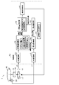
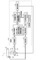
- FIG. 4 is a block configuration diagram of the position detection device 1.
- FIG. In the figure, the object to be driven 40 and the magnetic poles 34 of the sensor magnet 33 are shown in a simplified manner.
- the motor 30 that rotates in the pan direction will be described as an example, but the same applies to the motor 30 that rotates in the tilt direction.
- the position detection device 1 includes a motor 30, a cycle sensor 10, an origin sensor 20, and a control section 50.
- the motor 30, period sensor 10 and origin sensor 20 are as described above.
- the control unit 50 includes AD conversion units 51 and 52, a rotation amount calculation unit 53, an origin acquisition unit 54, an origin setting unit 55, a rotation amount setting unit 56, a drive control unit 59, and a storage unit 60.
- the control unit 50 is configured by a processor such as a CPU (Central Processing Unit), a storage unit 60 having a volatile memory and a nonvolatile memory, and programs stored in the storage unit 60 .
- a functional block configuration of the control unit 50 is realized by executing the above program.
- the AD converter 51 acquires the waveform signal s1 output from the period sensor 10, performs AD conversion, and outputs it to the rotation amount calculator 53. Based on the signal output from the AD conversion unit 51, the rotation amount calculation unit 53 calculates the count value c, the motor rotation amount r within the cycle, and the motor cumulative rotation amount rc.
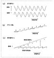
- FIG. 5 shows the waveform signal s1 input to the control unit 50 of the position detection device 1, the count value c calculated by the control unit 50, the rotation amount r within the period of the motor 30, and the cumulative rotation amount rc of the motor 30. It is a figure which shows.
- the waveform signal s1, the count value c, the intra-cycle rotation amount r, and the cumulative rotation amount rc are expressed like analog data for easy understanding.
- the horizontal axis of FIG. 5 is the rotation angle of the motor 30 when the motor 30 is rotated from one end to the other end within the movable range of the motor 30 .
- the control unit 50 receives two-phase waveform signals s1 that are 90 degrees out of phase.
- Each of the two-phase waveform signals s1 is a sinusoidal signal, and the amplitude on the vertical axis corresponds to the output voltage of the period sensor 10.
- (b) of FIG. 5 is the count value c obtained by accumulating the cycles included in the one-phase waveform signal s1 out of the two-phase waveform signals s1. For example, when the waveform signal s1 has 432 cycles when the motor 30 is rotated by 360°, one cycle is about 0.83°. counted up.
- (c) of FIG. 5 is a sawtooth waveform signal s1a that is calculated and generated based on the two-phase waveform signal s1.
- the waveform signal s1a has the same period as the one-phase waveform signal s1 of the two-phase waveform signals s1, and its amplitude changes in proportion to the rotation angle of the motor 30.
- the rotation amount calculation unit 53 shown in FIG. 4 acquires the rotation angle of the motor 30 within the cycle, that is, the in-cycle rotation amount r by reading the sawtooth waveform signal s1a. Further, the rotation amount calculation unit 53 acquires the cumulative rotation amount rc (see FIG. 5C) of the motor 30 by accumulating the in-cycle rotation amount r of each period. The rotation amount calculation unit 53 obtains the rotation angle information including the count value c, the in-cycle rotation amount r, and the cumulative rotation amount rc of the motor 30 through the origin acquisition unit 54, the origin setting unit 55, the rotation amount setting unit 56, and the memory. Output to unit 60 . These pieces of rotation angle information are used when setting the origin of the motor 30 and when setting the amount of rotation of the motor 30 .
- the AD converter 52 shown in FIG. 4 acquires the origin detection signal s2 output from the origin sensor 20 and performs AD conversion.
- the AD converter 52 outputs the AD-converted origin detection signal s ⁇ b>2 to the origin acquirer 54 .
- the origin acquisition unit 54 acquires the position of the origin based on the origin detection signal s2 and the rotation angle information output from the rotation amount calculation unit 53. Specifically, the origin acquisition unit 54 acquires the count value c when the origin sensor 20 detects the origin and the rotation amount r within the cycle of the motor 30 from the rotation amount calculation unit 53, and specifies the position of the origin. Origin information including the position of the origin specified by the origin acquisition unit 54 is output to the origin setting unit 55 and the storage unit 60 .
- the storage unit 60 stores the origin information output from the origin acquisition unit 54 and the like.
- the origin information includes the aforementioned rotation angle information.
- the origin setting unit 55 sets the origin based on the origin information output from the origin acquisition unit 54 when initializing the origin of the motor 30 . Further, when resetting the origin of the motor 30 , the origin setting unit 55 resets the origin based on the origin information output from the origin acquisition unit 54 and the origin information read from the storage unit 60 .
- the origin setting information set by the origin setting section 55 is output to the rotation amount setting section 56 . Specific examples of these will be described later.
- the rotation amount setting unit 56 determines the cumulative rotation amount rc of the motor 30 with reference to the origin. It sets and outputs to the drive control unit 59 .
- the drive control section 59 controls rotation of the motor 30 based on the signal output from the rotation amount setting section 56 .
- the control unit 50 obtains the in-cycle rotation amount r of the motor 30 in each of a plurality of cycles and the count value c, which is the integrated value of the plurality of cycles, based on the waveform signal s1, and also detects the origin.
- the origin of the motor 30 is obtained based on the signal s2.
- the control unit 50 can acquire the cumulative rotation amount rc, which is the cumulative value of the in-cycle rotation amount r of the motor 30 with reference to the origin, and can control the rotation of the motor 30 .
- FIG. 6 A method of setting the origin of the position detection device 1 will be described with reference to FIGS. 6 to 11.
- FIG. In this example, a scene of initial setting of the origin of the motor 30 and a scene of resetting will be described separately.
- the motor 30 that rotates in the pan direction will be described here as an example, the same applies to the motor 30 that rotates in the tilt direction.
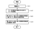
- FIG. 6 is a flowchart showing the operation of the position detection device 1 when initializing the origin of the motor 30.
- FIG. FIG. 7 is a diagram showing processing executed by the position detection device 1 when initializing the origin of the motor 30. As shown in FIG.
- step S11 when the power of the position detection device 1 is turned on, information about the origin of the motor 30 is initialized (step S11).
- control unit 50 rotates the motor 30 until the origin of the motor 30 is detected.
- This rotation of the motor 30 causes the origin sensor 20 to detect the origin of the motor 30 (step S12).
- the origin sensor 20 outputs an origin detection signal s2 to the origin acquisition section 54 .
- the period sensor 10 outputs the waveform signal s1 to the rotation amount calculation section 53 .
- the origin acquisition unit 54 acquires from the rotation amount calculation unit 53 the first count value c1 and the first in-period rotation amount r1 when the origin sensor 20 detects the origin. Specifically, the origin acquisition unit 54 obtains a first count value c1, which is an integrated value of a plurality of cycles when the origin detection signal s2 is acquired, and a cycle of the motor 30 corresponding to the first count value c1. A first intra-cycle rotation amount r ⁇ b>1 that is an intra-cycle rotation amount is acquired from the rotation amount calculation unit 53 . The origin acquisition unit 54 identifies the position of the origin based on the acquired first count value c1 and the first in-period rotation amount r1 (step S13).
- FIG. 8 is a diagram showing the origin set in the initial settings.
- the upper part of FIG. 8 shows a count value c indicating an integrated value of a plurality of cycles, and a first count value c1(n) which is an integrated value of a plurality of cycles when the origin detection signal s2 is acquired. ing. It is assumed that the actual count value is shown in parentheses of the count value c1.
- the first intra-cycle rotation amount r1 which is the intra-cycle rotation amount of the motor 30 with the period corresponding to the first count value c1(n)
- the position of the white circle coincides with the rising trigger of the origin detection signal s2 shown in the lower part of FIG.
- the control unit 50 stores the first count value c1(n) and the first in-period rotation amount r1 acquired by the origin acquisition unit 54 in the storage unit 60 (step S14). Initial setting of the origin of the motor 30 is completed by these steps S11 to S13.
- the control unit 50 of the position detection device 1 controls the rotation of the motor 30 based on the initially set origin.
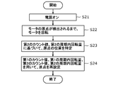
- FIG. 9 is a flowchart showing the operation of the position detection device 1 when resetting the origin of the motor 30.
- FIG. FIG. 10 is a diagram showing processing executed by the position detection device 1 when resetting the origin of the motor.
- step S21 when the position detection device 1 is powered on, the temporarily stored data is initialized (step S21). It should be noted that the first count value c1(n) and the first intra-cycle rotation amount r1 in the storage unit 60 are not erased and are continuously stored.
- control unit 50 rotates the motor 30 until the origin of the motor 30 is detected.
- This rotation of the motor 30 causes the origin sensor 20 to detect the origin of the motor 30 (step S22).
- the origin sensor 20 outputs an origin detection signal s2 to the origin acquisition section 54 .
- the period sensor 10 outputs the waveform signal s1 to the rotation amount calculation section 53 .
- the origin acquisition unit 54 acquires from the rotation amount calculation unit 53 the second count value c2 and the second in-period rotation amount r2 when the origin sensor 20 detects the origin. Specifically, the origin acquisition unit 54 obtains a second count value c2, which is an integrated value of a plurality of cycles when the origin detection signal s2 is acquired, and a cycle of the motor 30 corresponding to the second count value c2. A second intra-cycle rotation amount r ⁇ b>2 that is an intra-cycle rotation amount is acquired from the rotation amount calculation unit 53 . The origin acquisition unit 54 identifies the position of the origin based on the acquired second count value c2 and second in-cycle rotation amount r2 (step S23). Origin information about the origin acquired by the origin acquisition unit 54 , that is, the second count value c ⁇ b>2 and the second in-cycle rotation amount r ⁇ b>2 are output to the origin setting unit 55 .
- the origin setting unit 55 stores the first count value c1(n) and the first in-cycle rotation amount r1 stored in the storage unit 60, the second count value c2 calculated in step S23, and the second in-cycle rotation amount r1.
- the origin is reset using the amount of rotation r2 (step S24).
- FIG. 11 is a diagram showing the origin set by resetting.
- a count value c2 indicating an integrated value of a plurality of cycles, and a second count value c2 (n -1) is shown. It is assumed that the actual count value is shown in parentheses of the count value c2.
- the second in-cycle rotation amount r2 which is the in-cycle rotation amount of the motor 30 with the period corresponding to the second count value c2(n ⁇ 1), is indicated by black circles. is indicated. The position of the black circle coincides with the rising trigger of the origin detection signal s2 shown in the lower part of FIG. 11(a).
- the second intra-period rotation amount r2 corresponding to the origin detection signal s2 is the first rotation amount within the period corresponding to the first count value c1(n). It is within ⁇ 0.5 cycles with the in-cycle rotation amount r1 as a reference.
- This configuration is realized by designing the repetitive detection error ⁇ when detecting the origin to be smaller than the rotation range ⁇ of the motor 30 corresponding to each of the plurality of cycles detected by the cycle sensor 10. be done. This design makes it possible to accurately reproduce the position of the origin.
- the control unit 50 when the second in-cycle rotation amount r2 is positioned in a cycle different from the cycle corresponding to the first count value c1(n), controls the first count value c1(n).
- the origin is corrected by matching the count value c1(n) of the second count value c2(n ⁇ 1).
- the count value is decremented by one to reach the first count value c1( n) to the count value c2(n-1).
- the position of the origin is a value represented by the count value c2(n-1) and the second in-cycle rotation amount r2.
- the control unit 50 when the second in-period rotation amount r2 is positioned in the same period as the period corresponding to the first count value c1(n), the control unit 50 The origin is set using the first count value c1(n) as is. That is, in this example, since the second in-cycle rotation amount r2 is at the same count value c2(n) as the first count value c1(n), the value of the first count value c1(n) is maintained.
- the position of the origin is a value represented by the count value c1(n) and the second in-cycle rotation amount r2.
- the origin reset as described above will be the origin when the power is turned on again.
- the reset origin setting information is output to the rotation amount setting section 56 .
- the rotation amount setting unit 56 determines the cumulative rotation amount rc of the motor 30 with reference to the origin. It sets and outputs to the drive control unit 59 .
- FIG. 12 is a diagram showing another example of the origin set in the initial setting.
- the upper part of FIG. 12 shows a count value c indicating an integrated value of a plurality of cycles, and a first count value c1(n) which is an integrated value of a plurality of cycles when the origin detection signal s2 is acquired.
- the first in-cycle rotation amount r1 which is the in-cycle rotation amount of the motor 30 with the period corresponding to the first count value (n)
- the position of the white circle coincides with the rising trigger of the origin detection signal s2 shown in the lower part of FIG.
- the control unit 50 stores the first count value (n) and the first in-period rotation amount r1 acquired by the origin acquisition unit 54 in the storage unit 60 .
- FIG. 13 is a diagram showing another example of the origin set by resetting.
- a count value c2 indicating an integrated value of a plurality of cycles, and a second count value c2 (n+1 )It is shown.
- the second intra-cycle rotation amount r2 which is the intra-cycle rotation amount of the motor 30 with the period corresponding to the second count value (n+1)
- the position of the black circle coincides with the rising trigger of the origin detection signal s2 shown in the lower part of FIG. 13(a).
- the second in-cycle rotation amount r2 corresponding to the origin detection signal s2 is the first rotation amount within the cycle corresponding to the first count value c1(n). It is within ⁇ 0.5 cycles with the in-cycle rotation amount r1 as a reference.
- This configuration is realized by designing the repetitive detection error ⁇ when detecting the origin to be smaller than the rotation range ⁇ of the motor 30 corresponding to each of the plurality of cycles detected by the cycle sensor 10. be done. This design makes it possible to accurately reproduce the position of the origin.
- the control unit 50 controls the first rotation amount r2 when the second in-period rotation amount r2 is positioned in a period different from the period corresponding to the first count value (n).
- the origin is corrected by matching the count value c1(n) with the second count value c2(n+1).
- the count value is incremented by one to reach the first count value c1(n). to the count value c2(n+1).
- the position of the origin is a value represented by the count value c2(n+1) and the second in-cycle rotation amount r2.
- the control unit 50 controls the second rotation amount r2 when the second intra-period rotation amount r2 is positioned in the same period as the period corresponding to the first count value (n).
- the origin is set using the count value c2(n) of 2 as it is. That is, in this example, since the second in-cycle rotation amount r2 is at the same count value c2(n) as the first count value c1(n), the value of the first count value c1(n) is maintained.
- the position of the origin is a value represented by the count value c1(n) and the second in-cycle rotation amount r2.
- the origin reset as described above will be the origin when the power is turned on again.
- the position detection device 1 includes the motor 30 that rotates the driven object 40 and the period sensor 10 that detects a plurality of periods included in periodic changes generated by the rotation of the motor 30. , an origin sensor 20 that detects the origin in the rotation direction of the motor 30 , and a control unit 50 that controls the rotation of the motor 30 based on signals output from the cycle sensor 10 and the origin sensor 20 .
- a repetitive detection error ⁇ when the origin sensor 20 detects the origin is smaller than the rotation range ⁇ of the motor 30 corresponding to each of the plurality of cycles detected by the cycle sensor 10 .
- the position of the origin detected when resetting the origin can be changed to the origin.
- the position of the origin detected when the is initialized can be corrected in accordance with the position of the origin detected when the is initialized.
- the position of the origin can be accurately reproduced in the position detection device 1 .
- the motor 30 has a plurality of magnetic poles 34 arranged along the direction of rotation.
- the plurality of magnetic poles 34 rotates as the motor 30 rotates.
- a plurality of cycles may be detected by detecting changes in the generated magnetic field.
- the period sensor 10 detects a plurality of periods due to changes in the magnetic field, so that the rotation range ⁇ of the motor 30 corresponding to the plurality of periods can be obtained with high accuracy.
- the position of the origin can be acquired with high accuracy, and the position of the origin can be reproduced with high accuracy in the position detection device 1 .
- the period may correspond one-to-one with the magnetization period of the plurality of magnetic poles 34 arranged along the direction of rotation.
- the period detected by the period sensor 10 corresponds to the magnetization period of the plurality of magnetic poles 34 on a one-to-one basis, so that the rotation range ⁇ of the motor 30 corresponding to the plurality of periods can be obtained with high accuracy.
- the position of the origin can be acquired with high accuracy, and the position of the origin can be reproduced with high accuracy in the position detection device 1 .
- each of the repetitive detection error ⁇ and the rotation range ⁇ of the motor 30 may be a value represented by an angle in the rotation direction.
- the period sensor 10 may detect the period a plurality of times within the movable range of the motor 30, and the origin sensor 20 may detect the origin once within the movable range of the motor 30.
- the period sensor 10 detects more periods than the origin sensor 20
- the position of the origin can be accurately obtained using the period sensor 10 and the origin sensor 20. can be reproduced with high accuracy.
- the period sensor 10 outputs a waveform signal s1 having a plurality of periods to the control unit 50
- the origin sensor 20 outputs an origin detection signal s2 indicating that the origin has been detected to the control unit 50
- the control unit 50 obtains the in-cycle rotation amount r of the motor 30 in each of a plurality of cycles based on the waveform signal s1 and the count value c, which is the integrated value of the plurality of cycles, and the motor 30 based on the origin detection signal s2.
- the rotation of the motor 30 may be controlled by obtaining the cumulative rotation amount rc, which is the cumulative value of the in-cycle rotation amount r of the motor 30 with reference to the origin.
- the origin of the motor 30 can be obtained with high accuracy based on the waveform signal s1 and the origin detection signal s2. Further, by acquiring the cumulative rotation amount rc of the motor 30 with reference to the origin, it is possible to improve the accuracy of position control of the rotation of the motor 30 .
- the period sensor 10 outputs a waveform signal s1 having a plurality of periods to the control unit 50
- the origin sensor 20 outputs an origin detection signal s2 indicating that the origin has been detected to the control unit 50
- the control unit 50 1)
- a first count that is an integrated value of a plurality of periods when the origin detection signal s2 is obtained.
- a value c1 and a first in-cycle rotation amount r1, which is an in-cycle rotation amount of the motor 30 in a period corresponding to the first count value c1, are calculated, and 2) when resetting the origin of the motor 30, , based on the waveform signal s1 output from the cycle sensor 10, a second count value c2 that is an integrated value of a plurality of cycles when the origin detection signal s2 is acquired, and a cycle corresponding to the second count value c2
- a second intra-cycle rotation amount r2, which is an intra-cycle rotation amount of the motor 30, is calculated, and the first intra-cycle rotation amount r1, the second intra-cycle rotation amount r2, the first count value c1, and the second A count value c2 of 2 may be used to set the origin.
- the origin is reset. It is possible to correct the position of the origin detected when setting the origin to match the position of the origin detected when the origin was initialized. As a result, the position of the origin can be accurately reproduced in the position detection device 1 .
- the second intra-cycle rotation amount r2 may be within ⁇ 0.5 cycles with reference to the first intra-cycle rotation amount r1 of the cycle corresponding to the first count value c1.
- the position of the origin detected when resetting the origin is Correction can be made in accordance with the position of the origin detected when the origin is initialized. As a result, the position of the origin can be accurately reproduced in the position detection device 1 .
- the control unit 50 sets the first count value c1 to the second count value c2.
- the origin may be set by matching.
- the position detection device 1 further includes a storage unit 60 that stores the first count value c1 and the first in-period rotation amount r1.
- the origin may be set using the count value c1 and the first intra-cycle rotation amount r1, and the second count value c2 and the second intra-cycle rotation amount r2.
- the position of the origin detected when resetting the origin is stored in the storage unit 60. Correction can be made in accordance with the position of the origin. As a result, the position of the origin can be accurately reproduced in the position detection device 1 .
- the imaging device 5 includes the position detection device 1 described above and a driven object 40 including a camera 45 .
- the imaging device 5 having the position detection device 1 capable of accurately reproducing the position of the origin.
- the period sensor 10 of the above embodiment is not limited to a magnetic sensor.
- the periodic sensor may be any sensor that detects periodic changes, and may be an optical sensor.
- the origin sensor 20 of the embodiment described above is not limited to a transmissive photoelectric sensor.
- the origin sensor can detect the origin of the motor 30, and may be a reflective photoelectric sensor, a magnetic sensor, or a mechanical switch sensor.
- the following origin setting method may be executed. That is, the method of setting the origin of the position detection device includes: the motor 30 that rotates the driven object 40; Origin setting of a position detection device 1 comprising an origin sensor 20 for detecting an origin in a direction, and a control section 50 for controlling rotation of a motor 30 based on signals output from each of the period sensor 10 and the origin sensor 20. 1) the period sensor 10 outputs a waveform signal s1 having a plurality of periods to the control unit 50; and 2) the origin sensor 20 controls the origin detection signal s2 indicating that the origin has been detected.
- a second intra-cycle rotation amount r2 which is an intra-cycle rotation amount of the motor 30 with a period corresponding to c2, is calculated, and a first intra-cycle rotation amount r1, a second intra-cycle rotation amount r2, and a first intra-cycle rotation amount r2 are calculated. and setting an origin using the count value c1 and the second count value c2.
- General or specific aspects of the present disclosure may be implemented in a system, apparatus, method, integrated circuit, computer program, or recording medium such as a computer-readable CD-ROM. It may also be implemented in any combination of systems, devices, methods, integrated circuits, computer programs and recording media.
- the division of functional blocks in the block diagram is an example, and a plurality of functional blocks can be realized as one functional block, one functional block can be divided into a plurality of functional blocks, and some functions can be moved to other functional blocks.
- single hardware or software may process the functions of a plurality of functional blocks having similar functions in parallel or in a time-sharing manner.
- each component for example, a processing unit such as a control unit
- each component is implemented by dedicated hardware or by executing a software program suitable for each component. good too.
- Each component may be implemented by a program execution unit such as a CPU (Central Processing Unit) or processor reading and executing a software program recorded on a recording medium such as a hard disk or semiconductor memory.
- each component may be a circuit (or integrated circuit). These circuits may form one circuit as a whole, or may be separate circuits. These circuits may be general-purpose circuits or dedicated circuits.
- the position detection device and the like of the present disclosure can be used for surveillance camera devices and the like.
Landscapes
- Physics & Mathematics (AREA)
- General Physics & Mathematics (AREA)
- Engineering & Computer Science (AREA)
- Power Engineering (AREA)
- Transmission And Conversion Of Sensor Element Output (AREA)
Abstract
Description
[位置検出装置および撮像装置の構成]
実施の形態に係る位置検出装置および撮像装置の構成について、図1~図5を参照しながら説明する。
位置検出装置1の原点設定方法について、図6~図11を参照しながら説明する。この例ではモータ30の原点を初期設定する場面と、再設定する場面とに分けて説明する。なお、ここでは、パン方向に回転するモータ30を例に挙げて説明するが、チルト方向に回転するモータ30についても同様である。
次に、原点を設定する他の例について説明する。
以上のように、本実施の形態に係る位置検出装置1は、駆動対象体40を回転させるモータ30と、モータ30の回転によって発生する周期的変化に含まれる複数の周期を検出する周期センサ10と、モータ30の回転方向における原点を検出する原点センサ20と、周期センサ10および原点センサ20のそれぞれから出力された信号に基づいて、モータ30の回転を制御する制御部50と、を備える。原点センサ20によって原点を検出する際の繰り返し検出誤差αは、周期センサ10によって検出される複数の周期のそれぞれの周期に対応するモータ30の回転範囲βよりも小さい。
以上、実施の形態について説明したが、本開示は、このような実施の形態に限定されるものではない。
5 撮像装置
10、10a、10b 周期センサ
20、20a、20b 原点センサ
30、30a、30b モータ
31 モータ本体
33 センサマグネット
34 磁極
40 駆動対象体
41 第1基台
42 第2基台
45 カメラ
50 制御部
51 AD変換部
52 AD変換部
53 回転量演算部
54 原点取得部
55 原点設定部
56 回転量設定部
59 駆動制御部
60 記憶部
c、c1、c2 カウント値
s1、s1a 波形信号
s2 原点検出信号
r、r1、r2 周期内回転量
rc 累積回転量
α 原点を検出する際の繰り返し検出誤差
β 各周期に対応するモータの回転範囲
Claims (11)
- 駆動対象体を回転させるモータと、
前記モータの回転によって発生する周期的変化に含まれる複数の周期を検出する周期センサと、
前記モータの回転方向における原点を検出する原点センサと、
前記周期センサおよび前記原点センサのそれぞれから出力された信号に基づいて、前記モータの回転を制御する制御部と、
を備え、
前記原点センサによって前記原点を検出する際の繰り返し検出誤差は、前記周期センサによって検出される前記複数の周期のそれぞれの周期に対応する前記モータの回転範囲よりも小さい
位置検出装置。 - 前記モータは、前記回転方向に沿って並ぶ複数の磁極を有し、
前記複数の磁極は、前記モータの回転に伴って回転移動し、
前記周期センサは、前記複数の磁極の前記回転移動により発生する磁界の変化を検出することで、前記複数の周期を検出する
請求項1に記載の位置検出装置。 - 前記周期は、前記回転方向に沿って並ぶ前記複数の磁極の着磁周期と一対一で対応している
請求項2に記載の位置検出装置。 - 前記繰り返し検出誤差および前記モータの回転範囲のそれぞれは、前記回転方向の角度で表される値である
請求項1~3のいずれか1項に記載の位置検出装置。 - 前記周期センサは、前記モータの可動範囲において前記周期を複数回検出し、
前記原点センサは、前記モータの可動範囲において前記原点を1回検出する
請求項1~4のいずれか1項に記載の位置検出装置。 - 前記周期センサは、前記複数の周期を有する波形信号を前記制御部へ出力し、
前記原点センサは、前記原点を検出したことを示す原点検出信号を前記制御部へ出力し、
前記制御部は、前記波形信号に基づいて前記複数の周期のそれぞれの周期における前記モータの周期内回転量および前記複数の周期の積算値であるカウント値を求め、ならびに、前記原点検出信号に基づいて前記モータの前記原点を求めることで、前記原点を基準とする前記モータの周期内回転量の累積値である累積回転量を取得し、前記モータの回転を制御する
請求項1~5のいずれか1項に記載の位置検出装置。 - 前記周期センサは、前記複数の周期を有する波形信号を前記制御部へ出力し、
前記原点センサは、前記原点を検出したことを示す原点検出信号を前記制御部へ出力し、
前記制御部は、
1)前記モータの原点を初期設定する際に、前記周期センサから出力された前記波形信号に基づいて、前記原点検出信号を取得した時の前記複数の周期の積算値である第1のカウント値と、前記第1のカウント値に対応する前記周期の前記モータの周期内回転量である第1の周期内回転量と、を算出し、
2)前記モータの原点を再設定する際に、前記周期センサから出力された前記波形信号に基づいて、前記原点検出信号を取得した時の前記複数の周期の積算値である第2のカウント値と、前記第2のカウント値に対応する前記周期の前記モータの周期内回転量である第2の周期内回転量と、を算出し、前記第1の周期内回転量、前記第2の周期内回転量、前記第1のカウント値および前記第2のカウント値を用いて、前記原点を設定する
請求項1~5のいずれか1項に記載の位置検出装置。 - 前記第2の周期内回転量は、前記第1のカウント値に対応する前記周期の前記第1の周期内回転量を基準として、±0.5周期以内にある
請求項7に記載の位置検出装置。 - 前記制御部は、前記第2の周期内回転量が、前記第1のカウント値に対応する前記周期と異なる周期に位置する場合に、前記第1のカウント値を前記第2のカウント値に一致させることで、前記原点を設定する
請求項8に記載の位置検出装置。 - さらに、前記第1のカウント値および前記第1の周期内回転量が保存される記憶部を備え、
前記制御部は、前記記憶部に保存された前記第1のカウント値および前記第1の周期内回転量と、前記第2のカウント値および前記第2の周期内回転量とを用いて、前記原点を設定する
請求項7~9のいずれか1項に記載の位置検出装置。 - 請求項1~10のいずれか1項に記載の位置検出装置と、
カメラを含む前記駆動対象体と、
を備える撮像装置。
Priority Applications (2)
| Application Number | Priority Date | Filing Date | Title |
|---|---|---|---|
| JP2023535187A JPWO2023286520A1 (ja) | 2021-07-14 | 2022-06-16 | |
| CN202280045254.8A CN117561422A (zh) | 2021-07-14 | 2022-06-16 | 位置检测装置以及摄像装置 |
Applications Claiming Priority (2)
| Application Number | Priority Date | Filing Date | Title |
|---|---|---|---|
| JP2021116056 | 2021-07-14 | ||
| JP2021-116056 | 2021-07-14 |
Related Child Applications (1)
| Application Number | Title | Priority Date | Filing Date |
|---|---|---|---|
| US18/404,360 Continuation US20240159571A1 (en) | 2021-07-14 | 2024-01-04 | Position detection device and imaging device |
Publications (1)
| Publication Number | Publication Date |
|---|---|
| WO2023286520A1 true WO2023286520A1 (ja) | 2023-01-19 |
Family
ID=84919279
Family Applications (1)
| Application Number | Title | Priority Date | Filing Date |
|---|---|---|---|
| PCT/JP2022/024177 WO2023286520A1 (ja) | 2021-07-14 | 2022-06-16 | 位置検出装置および撮像装置 |
Country Status (3)
| Country | Link |
|---|---|
| JP (1) | JPWO2023286520A1 (ja) |
| CN (1) | CN117561422A (ja) |
| WO (1) | WO2023286520A1 (ja) |
Citations (3)
| Publication number | Priority date | Publication date | Assignee | Title |
|---|---|---|---|---|
| JP2009036760A (ja) * | 2007-07-06 | 2009-02-19 | Victor Co Of Japan Ltd | 原点検出装置及び原点検出方法 |
| JP2010219880A (ja) | 2009-03-17 | 2010-09-30 | Victor Co Of Japan Ltd | 原点検出方法、原点検出装置及び監視カメラ装置 |
| JP2015038443A (ja) * | 2013-08-19 | 2015-02-26 | キヤノン株式会社 | エンコーダ及びエンコーダの原点リセット方法 |
-
2022
- 2022-06-16 JP JP2023535187A patent/JPWO2023286520A1/ja active Pending
- 2022-06-16 WO PCT/JP2022/024177 patent/WO2023286520A1/ja active Application Filing
- 2022-06-16 CN CN202280045254.8A patent/CN117561422A/zh active Pending
Patent Citations (3)
| Publication number | Priority date | Publication date | Assignee | Title |
|---|---|---|---|---|
| JP2009036760A (ja) * | 2007-07-06 | 2009-02-19 | Victor Co Of Japan Ltd | 原点検出装置及び原点検出方法 |
| JP2010219880A (ja) | 2009-03-17 | 2010-09-30 | Victor Co Of Japan Ltd | 原点検出方法、原点検出装置及び監視カメラ装置 |
| JP2015038443A (ja) * | 2013-08-19 | 2015-02-26 | キヤノン株式会社 | エンコーダ及びエンコーダの原点リセット方法 |
Also Published As
| Publication number | Publication date |
|---|---|
| CN117561422A (zh) | 2024-02-13 |
| JPWO2023286520A1 (ja) | 2023-01-19 |
Similar Documents
| Publication | Publication Date | Title |
|---|---|---|
| JP6154401B2 (ja) | 高分解能アブソリュート・エンコーダ | |
| JP5676704B2 (ja) | アナログ回転センサのための方法および装置 | |
| US9304019B2 (en) | Rotation detection apparatus, motor control apparatus, motor driven apparatus, method of correcting rotation detection apparatus, and non-transitory computer-readable storage medium storing correction program | |
| US6914543B2 (en) | Method for initializing position with an encoder | |
| JP5736518B2 (ja) | 撮像レンズ鏡筒およびその動作制御方法 | |
| US20170138761A1 (en) | Ring magnetic encoder, manufacturing device for ring magnetic encoder, rotary shaft offset detecting method, and human-machine interface device thereof | |
| US20060192092A1 (en) | Optical encoder | |
| JP2014124000A (ja) | アクチュエータの制御装置 | |
| JP3920113B2 (ja) | 回転角検出装置 | |
| JP5789895B2 (ja) | 位置検出ユニット、及びそれを備えたレンズユニット、カメラ、及びレンズユニットの製造方法、位置検出方法 | |
| US8942553B2 (en) | Lens device and position detection method of movable optical element | |
| WO2023286520A1 (ja) | 位置検出装置および撮像装置 | |
| JP2006246642A (ja) | モータ制御回路及びモータ制御方法 | |
| WO2014034316A1 (ja) | 撮像レンズ鏡筒およびその動作制御方法 | |
| JP2017129452A (ja) | エンコーダ | |
| US9593965B2 (en) | Non-contact adjustable hysteretic magnetic encoder | |
| WO2023286521A1 (ja) | 位置検出装置および撮像装置 | |
| US20240159571A1 (en) | Position detection device and imaging device | |
| JP2000088600A (ja) | アクチュエータ及び移動位置検出方法 | |
| CN115833683A (zh) | 一种电角度偏移量的校准方法、装置和永磁同步电机 | |
| JP7158891B2 (ja) | モータ駆動装置およびモータ駆動方法 | |
| JP2009276128A (ja) | 位置検出装置 | |
| JP3318843B2 (ja) | 位置検出器の原点検出方法と検出システム | |
| JP2546323B2 (ja) | 多回転アブソリュートエンコーダ | |
| EP3032223B1 (en) | Non-contact adjustable hysteretic magnetic encoder |
Legal Events
| Date | Code | Title | Description |
|---|---|---|---|
| 121 | Ep: the epo has been informed by wipo that ep was designated in this application |
Ref document number: 22841864 Country of ref document: EP Kind code of ref document: A1 |
|
| WWE | Wipo information: entry into national phase |
Ref document number: 2023535187 Country of ref document: JP |
|
| WWE | Wipo information: entry into national phase |
Ref document number: 2022841864 Country of ref document: EP |
|
| NENP | Non-entry into the national phase |
Ref country code: DE |
|
| ENP | Entry into the national phase |
Ref document number: 2022841864 Country of ref document: EP Effective date: 20240214 |