WO2023286353A1 - 演算装置、光検出装置、及びゲイン算出方法 - Google Patents
演算装置、光検出装置、及びゲイン算出方法 Download PDFInfo
- Publication number
- WO2023286353A1 WO2023286353A1 PCT/JP2022/011275 JP2022011275W WO2023286353A1 WO 2023286353 A1 WO2023286353 A1 WO 2023286353A1 JP 2022011275 W JP2022011275 W JP 2022011275W WO 2023286353 A1 WO2023286353 A1 WO 2023286353A1
- Authority
- WO
- WIPO (PCT)
- Prior art keywords
- gain
- dark
- electrons
- photomultiplier tube
- digital signal
- Prior art date
- Legal status (The legal status is an assumption and is not a legal conclusion. Google has not performed a legal analysis and makes no representation as to the accuracy of the status listed.)
- Ceased
Links
Images



Classifications
-
- H—ELECTRICITY
- H01—ELECTRIC ELEMENTS
- H01J—ELECTRIC DISCHARGE TUBES OR DISCHARGE LAMPS
- H01J43/00—Secondary-emission tubes; Electron-multiplier tubes
- H01J43/04—Electron multipliers
-
- G—PHYSICS
- G01—MEASURING; TESTING
- G01J—MEASUREMENT OF INTENSITY, VELOCITY, SPECTRAL CONTENT, POLARISATION, PHASE OR PULSE CHARACTERISTICS OF INFRARED, VISIBLE OR ULTRAVIOLET LIGHT; COLORIMETRY; RADIATION PYROMETRY
- G01J1/00—Photometry, e.g. photographic exposure meter
- G01J1/42—Photometry, e.g. photographic exposure meter using electric radiation detectors
- G01J1/44—Electric circuits
-
- G—PHYSICS
- G01—MEASURING; TESTING
- G01J—MEASUREMENT OF INTENSITY, VELOCITY, SPECTRAL CONTENT, POLARISATION, PHASE OR PULSE CHARACTERISTICS OF INFRARED, VISIBLE OR ULTRAVIOLET LIGHT; COLORIMETRY; RADIATION PYROMETRY
- G01J1/00—Photometry, e.g. photographic exposure meter
- G01J1/42—Photometry, e.g. photographic exposure meter using electric radiation detectors
-
- H—ELECTRICITY
- H01—ELECTRIC ELEMENTS
- H01J—ELECTRIC DISCHARGE TUBES OR DISCHARGE LAMPS
- H01J43/00—Secondary-emission tubes; Electron-multiplier tubes
- H01J43/04—Electron multipliers
- H01J43/06—Electrode arrangements
- H01J43/10—Dynodes
Definitions
- the present disclosure relates to an arithmetic device, a photodetector, and a gain calculation method.
- a photodetector including a photomultiplier tube is known (for example, Patent Document 1).
- the amount of light incident on the photomultiplier tube is calculated based on the output signal from the photomultiplier tube.
- the gain of the photomultiplier tube is used to determine the amount of incident light from the output signal from the photomultiplier tube. Since this gain may change depending on the surrounding environment and usage conditions of the photomultiplier tube, it is required to measure the gain. Although it is conceivable to provide a dedicated circuit for measuring the gain, the circuit structure becomes complicated.
- the present disclosure describes an arithmetic device, a photodetector, and a gain calculation method capable of calculating the gain of a photomultiplier tube while suppressing complication of the circuit structure.
- a computing device is a device for calculating the gain of a photomultiplier tube.
- This arithmetic device includes an acquisition unit that acquires a digital signal based on the dark pulse output from the photomultiplier tube placed in the dark, and a total number of electrons of the dark pulse calculated based on the digital signal. and a calculation unit that calculates the gain based on the number.
- a digital signal based on the dark pulse output from the photomultiplier tube placed in the dark is obtained, and the total number of electrons of the dark pulse is calculated based on the digital signal. If the photomultiplier tube is placed in the dark, a single thermal electron can be generated and multiplied to produce a dark pulse. Therefore, since the total number of electrons in the dark pulse can correspond to the gain of the photomultiplier tube, the gain can be calculated based on the total number of electrons. As described above, since there is no need to provide a dedicated circuit for measuring the gain, it is possible to calculate the gain of the photomultiplier tube while suppressing the complication of the circuit structure.
- the digital signal may be generated by the AD converter quantizing the voltage signal obtained by current-voltage conversion of the dark pulse using the conversion coefficient with the AD converter at the sampling frequency.
- the calculator may calculate the total number of electrons based on the digital signal, the conversion coefficient, and the sampling frequency. In this case, since the conversion coefficient and sampling frequency used to generate the digital signal are taken into consideration, the calculation accuracy of the total number of electrons can be improved. As a result, it becomes possible to improve the calculation accuracy of the gain.
- the calculation unit calculates the area of the waveform of the digital signal, multiplies the area by the physical quantity per unit area obtained by dividing the quantization width of the AD converter by the sampling frequency, and the reciprocal of the conversion coefficient, and multiplies
- the total number of electrons may be calculated by dividing the result by the elementary charge.
- the coulomb amount of the dark pulse is obtained by multiplying the area of the waveform of the digital signal by the physical quantity per unit area and the reciprocal of the transform coefficient.
- the total number of electrons in the dark pulse is obtained by dividing the Coulomb amount of the dark pulse by the elementary charge. Since the physical quantity, conversion coefficient, and elementary charge per unit area are all constant values, the gain can be easily calculated simply by obtaining the area of the waveform of the digital signal.
- the calculation unit may calculate the total number of electrons for each of the plurality of dark pulses, or may calculate the gain based on the total number of electrons of the plurality of dark pulses.
- the total number of electrons may vary for each dark pulse. Therefore, by calculating the total number of electrons of a plurality of dark pulses and using the total number of electrons, the gain calculation accuracy can be improved.
- the calculation unit may calculate another gain at a supply voltage different from the voltage supplied to the photomultiplier tube when the dark pulse is generated.
- the gain at one supply voltage is used to calculate the gain at another supply voltage. Therefore, the gain at various supply voltages can be calculated without acquiring the dark pulse. As a result, it becomes possible to simplify the calculation of the gain for various supply voltages.
- a photodetector includes a photomultiplier tube and the arithmetic device.
- this photodetector is equipped with the arithmetic unit described above, it is possible to calculate the gain of the photomultiplier tube while suppressing complication of the circuit structure.
- a gain calculation method is a method for calculating the gain of a photomultiplier tube.
- This gain calculation method includes the steps of acquiring a digital signal based on a dark pulse output from the photomultiplier tube placed in the dark, calculating the total number of electrons of the dark pulse based on the digital signal, and calculating a gain based on the number.
- a digital signal based on a dark pulse output from a photomultiplier tube placed in the dark is obtained, and the total number of electrons in the dark pulse is calculated based on the digital signal. If the photomultiplier tube is placed in the dark, a single thermal electron can be generated and multiplied to produce a dark pulse. Therefore, since the total number of electrons in the dark pulse can correspond to the gain of the photomultiplier tube, the gain can be calculated based on the total number of electrons. As described above, since there is no need to provide a dedicated circuit for measuring the gain, it is possible to calculate the gain of the photomultiplier tube while suppressing the complication of the circuit structure.
- FIG. 1 is a configuration diagram schematically showing a photodetector including an arithmetic device according to one embodiment.
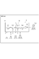
- FIG. 2 is a diagram for explaining a dark pulse generated from a photomultiplier tube placed in the dark.
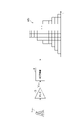
- FIG. 3 is a diagram for explaining digital signals acquired by the arithmetic unit shown in FIG.
- FIG. 4 is a block diagram showing the functional configuration of the arithmetic unit shown in FIG. 1;
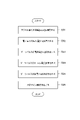
- FIG. 5 is a flow chart showing a gain calculation method performed by the arithmetic unit shown in FIG.
- FIG. 6 is a flowchart showing in detail the gain calculation process of FIG.
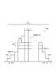
- FIG. 7 is a diagram for explaining the area of the waveform of the digital signal shown in FIG.
- FIG. 1 is a configuration diagram schematically showing a photodetector including an arithmetic device according to one embodiment.
- the photodetector 1 shown in FIG. 1 is a device that detects light.
- the photodetector 1 includes a photomultiplier tube (PMT) 2, an amplifier 3, an AD converter (Analog to Digital Converter) 4, a computer 5, an arithmetic unit 6, and a DA converter ( Digital to Analog Converter) 7 and a power supply 8 are provided.
- PMT photomultiplier tube
- AD converter Analog to Digital Converter
- a computer 5 an arithmetic unit 6
- DA converter Digital to Analog Converter
- the photomultiplier tube 2 is a structure that converts the light incident on the photomultiplier tube 2 (incident light) into a current signal.
- the photomultiplier tube 2 includes a photocathode 21, an electron multiplier section 22, and an anode 23 (see FIG. 2).
- the photocathode 21 is a member (cathode) that converts incident light into photoelectrons.
- the photocathode 21 generates photoelectrons according to the amount of incident light and emits the photoelectrons to the electron multiplier 22 .
- the photocathode 21 generates thermoelectrons in the dark and emits the thermoelectrons to the electron multiplier 22 .
- the dark state is a state in which incident light such as measurement light and background light is blocked.
- the electron multiplier section 22 is a section that multiplies photoelectrons and thermoelectrons emitted from the photocathode 21 .
- the electron multiplier section 22 includes a plurality of dynodes.
- the electron multiplier section 22 includes n dynodes (dynodes Dy1 to Dyn).
- the dynodes Dy1 to Dyn are arranged in multiple stages from the photocathode 21 toward the anode 23 in that order.
- the dynode Dy1 emits secondary electrons upon collision with photoelectrons or thermoelectrons emitted from the photocathode 21 . Photoelectrons or thermoelectrons are thereby multiplied.
- Dynode Dy1 emits secondary electrons to dynode Dy2 together with photoelectrons or thermoelectrons. After that, each of the dynodes Dy2 to Dyn-1 multiplies the electrons emitted from the preceding dynode and emits the multiplied electrons to the succeeding dynode. The final stage dynode Dyn emits the multiplied electrons to the anode 23 .
- the anode 23 collects the electrons multiplied by the electron multiplier 22 and outputs the collected electrons to the outside of the photomultiplier tube 2 as a current signal.
- the current signal is an analog signal.
- the amplifier 3 is a circuit that converts the current signal output from the photomultiplier tube 2 into a voltage signal.
- the voltage signal is an analog signal.
- the amplifier 3 converts the current signal into a voltage signal using the conversion factor Acv .
- Amplifier 3 outputs a voltage signal to AD converter 4 .
- the AD converter 4 is a circuit that converts the voltage signal output from the amplifier 3 into a digital signal.
- the AD converter 4 samples the voltage signal at the sampling frequency fs and quantizes the sampled voltage signal with a quantization width ⁇ d to generate a digital signal.
- AD converter 4 outputs a digital signal to arithmetic unit 6 .
- the computer 5 sets values of various parameters in the arithmetic device 6 .
- parameters include parameters for operation mode setting, conversion coefficient A cv , sampling frequency f s , quantization width ⁇ d, and voltage value of the voltage supplied to the photomultiplier tube 2 .
- a value indicating the operation mode of the photodetector 1 is set in the parameter for setting the operation mode.
- the operation modes include a photodetection mode in which the photodetector 1 performs normal photodetection and a gain calculation mode in which the photodetector 1 measures (calculates) the gain of the photomultiplier tube 2 .
- the computing device 6 is a device that performs computation using the digital signal output from the AD converter 4 .
- the computing device 6 is configured as circuitry including, for example, a processor, a memory, and a communication module. Examples of processors include microcomputers and CPUs (Central Processing Units). An FPGA (Field Programmable Gate Array) may be used instead of the processor.
- the computing device 6 performs computation according to the operation mode set by the computer 5 .
- the calculation device 6 calculates the amount of incident light based on the digital signal output from the AD converter 4 .
- arithmetic device 6 calculates the gain of photomultiplier tube 2 based on the digital signal output from AD converter 4 .
- the arithmetic device 6 outputs a control voltage corresponding to the voltage value of the supply voltage set by the computer 5 to the power supply 8 via the DA converter 7 .
- the control voltage is a voltage for causing the power supply 8 to supply a supply voltage having the voltage value.
- a power supply 8 is a device that applies a supply voltage to the photomultiplier tube 2 .
- the power supply 8 receives the control voltage via the DA converter 7 and applies a supply voltage corresponding to the control voltage to the photomultiplier tube 2 .
- the power supply 8 is, for example, a high voltage power supply.
- the photomultiplier tube 2, amplifier 3, and power supply 8 constitute a PMT module 10.
- FIG. 2 is a diagram for explaining a dark pulse generated from a photomultiplier tube placed in the dark.
- FIG. 3 is a diagram for explaining digital signals acquired by the arithmetic unit shown in FIG.
- the photomultiplier tube 2 is placed in a dark state where incident light is blocked.
- the photomultiplier tube 2 is placed, for example, in a dark room.
- the PMT module 10 may have a light shielding function (light shielding structure) for the photomultiplier tube 2, or the entire PMT module 10 may be arranged in the dark.
- Thermoelectrons (dark current) are generated from the photocathode 21 even when the photomultiplier tube 2 is placed in the dark.
- the thermoelectrons are multiplied by the electron multiplier 22 and the multiplied thermoelectrons are output from the anode 23 as an anode current.
- This anode current has a pulsed waveform and is therefore called a dark pulse.
- a dark pulse I dark generated in photomultiplier tube 2 is converted by amplifier 3 into a voltage signal V dark . Then, the voltage signal V dark is converted into a digital signal s(t) by the AD converter 4 and the digital signal s(t) is output to the arithmetic device 6 .
- the computing device 6 calculates the gain of the photomultiplier tube 2 based on the digital signal s(t). A gain calculation method will be described later.
- FIG. 4 is a block diagram showing the functional configuration of the arithmetic unit shown in FIG. 1;
- the computing device 6 functionally includes an acquisition unit 61 , an acquisition unit 62 , a calculation unit 63 , a storage unit 64 and an output unit 65 . Since the function (operation) of each functional unit will be described in detail in the explanation of the gain calculation method which will be described later, the function of each functional unit will be briefly described here.
- the acquisition unit 61 is a functional unit that acquires the value of each parameter from the computer 5 .
- the obtaining unit 61 obtains, for example, the parameters for setting the operation mode, the conversion coefficient Acv , the sampling frequency fs , the quantization width ⁇ d, and the voltage value of the voltage supplied to the photomultiplier tube 2 .
- the acquisition unit 62 is a functional unit that acquires digital signals from the AD converter 4 .
- the acquisition unit 62 acquires a digital signal corresponding to incident light.
- the acquisition unit 62 acquires a digital signal based on a dark pulse generated by multiplication of thermoelectrons in the photomultiplier tube 2 .
- the storage unit 64 is a functional unit that stores (stores) the estimated gain.
- the storage section 64 stores the estimated gain calculated by the calculation section 63 .
- the output unit 65 is a functional unit that outputs the calculation result of the calculation unit 63.
- the output section 65 When the operation mode is set to the light detection mode, the output section 65 outputs the amount of incident light.
- the output section 65 outputs the gain of the photomultiplier tube 2 .
- the output section 65 outputs the control voltage to the power supply 8 via the DA converter 7 .
- FIG. 5 is a flow chart showing a gain calculation method performed by the arithmetic unit shown in FIG.
- FIG. 6 is a flowchart showing in detail the gain calculation process of FIG.
- FIG. 7 is a diagram for explaining the area of the waveform of the digital signal shown in FIG. A series of processes shown in FIG. 5 is started, for example, when the operation mode is set to the gain calculation mode. Incidentally, as described above, the photomultiplier tube 2 is placed in the dark.
- the acquiring unit 61 acquires the value of each parameter (step S11).
- step S ⁇ b>11 the acquisition unit 61 acquires the conversion coefficient A cv , the sampling frequency f s , the quantization width ⁇ d, and the voltage value of the voltage supplied to the photomultiplier tube 2 .
- the acquisition unit 61 outputs the conversion coefficient A cv , the sampling frequency f s , and the quantization width ⁇ d to the calculation unit 63 and causes the output unit 65 to output the control voltage corresponding to the voltage value.
- Thermal electrons are generated from the photocathode 21 as described above.
- the thermal electrons are multiplied by the electron multiplier 22 and a dark pulse I dark is output from the anode 23 .
- the dark pulse I dark is then converted by the amplifier 3 into a voltage signal V dark .
- the voltage signal V dark is sampled at the sampling frequency fs , and the sampled voltage signal V dark is quantized with the quantization width ⁇ d to generate the digital signal s(t). be.
- the digital signal s(t) is input to the arithmetic device 6 . That is, the digital signal s(t) is input to the arithmetic unit 6 as discrete digital values.
- the acquiring unit 62 acquires the digital signal s(t) based on the dark pulse I dark (step S12). The acquisition unit 62 then outputs the digital signal s(t) to the calculation unit 63 .
- step S13 gain calculation processing is performed (step S13).
- step S13 as shown in FIG. 6, the calculator 63 first measures the area S total [unit: count] of the waveform of the digital signal s(t) (step S31).
- the digital signal s(t) has a pulse-like waveform from start time a to end time b.
- the area S total is obtained by summing the digital values from the start time a to the end time b.
- the calculator 63 calculates (measures) the area S total using the formula (1).
- the calculator 63 calculates the signal amount [unit: V ⁇ s] of the voltage signal V dark (step S32).
- the physical quantity ⁇ s [unit: V s/count] per unit bit (unit area) of the digital value is obtained by dividing the quantization width ⁇ d [unit: V/count] by the sampling frequency f s It is obtained by dividing by [unit: Hz].
- the signal amount of the voltage signal V dark is obtained by multiplying the area S total by the physical quantity ⁇ s.
- the calculation unit 63 calculates the signal amount of the voltage signal V dark using Equation (3).
- the signal amount of the voltage signal V dark may be expressed as "V dark " in the mathematical expressions.
- the calculator 63 calculates the current amount [unit: A ⁇ s] of the dark pulse I dark (step S33). Since the amplifier 3 converts the current signal into a voltage signal, the current amount of the dark pulse I dark can be obtained from the signal amount of the voltage signal V dark by using this inverse conversion. Specifically, as shown in Equation (4), the current amount of the dark pulse I dark is obtained by multiplying the signal amount of the voltage signal V dark by the reciprocal of the conversion coefficient A cv [unit: V/A]. Desired. The calculation unit 63 calculates the current amount of the dark pulse I dark using Equation (4). For convenience of explanation, the current amount of the dark pulse I dark may be expressed as "I dark " in the mathematical formula.
- the calculator 63 calculates the coulomb amount [unit: C] of the dark pulse I dark (step S34).
- 1 coulomb [C] is defined as the amount of electricity carried when a current of 1 ampere [A] flows for 1 second [s]. Therefore, 1 [A ⁇ s] can be replaced with 1 [C]. Therefore, as shown in equation (5), the coulomb amount of the dark pulse I dark is the same value as the current amount of the dark pulse I dark .
- the calculator 63 calculates the coulomb amount of the dark pulse I dark using Equation (5).
- the calculator 63 calculates the total number of electrons D electron [unit: number] of the dark pulse I dark (step S35).
- the amount of electric charge [C] per electron is called the elementary charge e. Therefore, as shown in equation (6), the total number of electrons D electron is obtained by dividing the Coulomb amount of the dark pulse I dark by the elementary charge e.
- the calculator 63 calculates the total number of electrons D electron using the equation (6). That is, the calculation unit 63 calculates the area S total of the waveform of the digital signal s(t), and the physical quantity ⁇ s per unit bit (unit area) obtained by dividing the quantization width ⁇ d by the sampling frequency fs .
- the total number of electrons D electron is calculated by multiplying the area S total by the reciprocal of the conversion coefficient A cv and dividing the multiplication result by the elementary charge e.
- the calculator 63 calculates the estimated gain ⁇ [unit: times] (step S36).
- the total number of electrons D electron is obtained by multiplying the number of electrons K electron [unit: pieces] incident on the first dynode Dy1 from the photocathode 21 (cathode) by the estimated gain ⁇ . sought by
- the dark pulse is mainly caused by thermoelectrons from the photocathode 21 .
- a dark pulse is discretely generated, and in most cases is generated from a single thermoelectron. From this, equation (7) can be simplified as equation (8).
- Equation (8) indicates that the total number of electrons D electron and the estimated gain ⁇ have the same value in an environment (dark state) in which thermal electrons can be measured. Therefore, the expression (9) is obtained by interchanging the right side and the left side of the expression (8).
- the calculation unit 63 calculates the estimated gain ⁇ using Equation (9).
- the calculation unit 63 stores the estimated gain ⁇ in the storage unit 64 (step S14).
- step S15 the calculation unit 63 determines whether or not to end the measurement.
- step S15 the calculator 63 determines not to end the measurement when the estimated gain ⁇ for the preset number of calculations has not been calculated.
- the calculation unit 63 determines to end the measurement when the estimated gain ⁇ for the number of calculations is calculated.
- the number of calculations is set to, for example, about 1000 times. If it is determined in step S15 that the measurement should not be terminated (step S15; NO), steps S12 to S15 are performed again.
- step S15 when it is determined in step S15 that the measurement is finished (step S15; YES), the calculation unit 63 reads out the estimated gains ⁇ for the number of calculations from the storage unit 64, and calculates the average value of the estimated gains ⁇ for the number of calculations. is calculated (step S16). The calculator 63 then outputs the average value to the output unit 65 as the gain of the photomultiplier tube 2 .
- the output unit 65 outputs the gain to the outside of the calculation device 6 (step S17).
- the output unit 65 outputs the gain to the computer 5 together with the voltage value of the supply voltage, for example.
- the computer 5 associates and stores the voltage value of the supply voltage and the gain.
- step S11 may be performed before the operation mode is set to the gain calculation mode.
- 1 [C] is equal to 1 [A ⁇ s]
- the coulomb amount of the dark pulse I dark is 1 ⁇ 10 ⁇ 12 C.
- the elementary charge e is 1.602 ⁇ 10 ⁇ 19 C
- the number of electrons D electron is 6.24 ⁇ 10 6 ( ⁇ (1 ⁇ 10 ⁇ 12 )/(1.602 ⁇ 10 ⁇ 19 )). Since 6.24 ⁇ 10 6 electrons are generated from one thermoelectron, the estimated gain ⁇ is estimated to be 6.24 ⁇ 10 6 .
- the above calculations are performed for the digital signal s(t) of 1000 or more waveforms, and the average value of the estimated gains ⁇ obtained by these calculations is used as the gain of the photomultiplier tube 2 .
- the acquisition unit 61 acquires the conversion coefficient A cv , the sampling frequency f s , the quantization width ⁇ d, the voltage value of the voltage supplied to the photomultiplier tube 2, and the gain associated with the voltage value as parameter values. Acquired from the computer 5 . Then, the acquisition unit 61 outputs the conversion coefficient A cv , the sampling frequency f s , the quantization width ⁇ d, and the gain to the calculation unit 63 and causes the output unit 65 to output the control voltage according to the voltage value.
- the acquisition unit 62 acquires the digital signal s(t) based on the incident light and outputs the digital signal s(t) to the calculation unit 63 .
- the calculation unit 63 calculates the incident light amount from the digital signal s(t) using the conversion coefficient A cv , the sampling frequency f s , the quantization width ⁇ d, and the gain, and outputs the incident light amount to the output unit 65.
- the output unit 65 outputs the amount of incident light to the outside of the computing device 6 .
- the digital signal s(t) based on the dark pulse I dark output from the photomultiplier tube 2 placed in the dark is obtained.
- the total number of electrons D electron of the dark pulse I dark is calculated based on the digital signal s(t).
- a single thermoelectron is generated and multiplied by the single thermoelectron to produce a dark pulse I dark . Therefore, since the total number of electrons D electron of the dark pulse I dark can correspond to the estimated gain ⁇ , the gain of the photomultiplier tube 2 can be calculated based on the total number of electrons D electron .
- the arithmetic device 6 and the gain calculation method there is no need to provide a dedicated circuit for measuring the gain, a structure for stabilizing the gain, and a reference light source. , the gain of the photomultiplier tube 2 can be calculated.
- the digital signal s(t) acquired by the arithmetic unit 6 is obtained by the voltage signal V dark obtained by current-voltage conversion of the dark pulse I dark using the conversion coefficient Acv by the amplifier 3, and the voltage signal V dark obtained by sampling by the AD converter 4. It is generated by quantizing at frequency fs .
- the calculator 63 calculates the total number of electrons D electron based on the digital signal s (t), the conversion coefficient Acv , and the sampling frequency fs. According to this configuration, the conversion coefficient A cv and the sampling frequency f s used to generate the digital signal s(t) are taken into account, so the calculation accuracy of the total number of electrons D electron can be improved. As a result, it becomes possible to improve the calculation accuracy of the gain.
- the coulomb amount of the dark pulse I dark is obtained by multiplying the waveform area S total of the digital signal s(t) by the physical quantity ⁇ s and the reciprocal of the conversion coefficient Acv . Then, the total electron number D electron of the dark pulse I dark is obtained by dividing the coulomb quantity of the dark pulse I dark by the elementary charge e. Since the physical quantity ⁇ s, the conversion coefficient A cv , and the elementary electric charge e are constant values, the gain can be easily calculated simply by obtaining the area S total .
- the total number of electrons D electron may vary for each dark pulse I dark .
- the calculator 63 calculates the total number of electrons D electron for each of the dark pulses I dark for a predetermined number of calculations, and calculates the gain based on these total number of electrons D electron .
- the calculator 63 calculates the average value of the estimated gain ⁇ obtained from each dark pulse I dark as the gain of the photomultiplier tube 2 .
- the calculator 63 calculates the average value of the total number of electrons D electron of the dark pulses I dark for the number of calculations as the gain of the photomultiplier tube 2 .
- photodetector according to the present disclosure is not limited to the above embodiments.
- each parameter may be set from an external computer.
- the photodetector 1 may not have the computer 5 .
- a supply voltage may be supplied to the photomultiplier tube 2 from an external power source.
- the photodetector 1 does not have to include the DA converter 7 and the power supply 8 .
- the calculator 63 uses the average value of the estimated gains obtained from a plurality of dark pulses as the gain of the photomultiplier tube 2, but the method of calculating the gain of the photomultiplier tube 2 is limited to this. can't
- the calculator 63 may use the estimated gain obtained from one dark pulse as the gain of the photomultiplier tube 2 .
- the calculator 63 may calculate the median value of the estimated gain obtained from a plurality of dark pulses as the gain of the photomultiplier tube 2 .
- the calculator 63 may calculate the gain for another supply voltage based on the gain calculated for one supply voltage.
- Another supply voltage is a supply voltage different from the supply voltage to the photomultiplier tube 2 when a dark pulse is generated in the gain calculation mode.
- the gain of the photomultiplier tube 2 can be expressed using a constant A, the voltage value V of the supply voltage, and the value kn.
- the value kn is a value determined by the structure of the photomultiplier tube 2 .
- the relationship between the supply voltage and the gain becomes a straight line with a slope equal to the value kn when drawn as a log-log graph.
- the gain at one supply voltage can be used to calculate the gain at another supply voltage. Therefore, the gain at various supply voltages can be calculated without acquiring the dark pulse. As a result, it becomes possible to simplify the calculation of the gain for various supply voltages.
- the computing device 6 may calculate the gain for each of the plurality of supply voltages using the gain calculation method described above.
- the photodetector 1 may further include a light source capable of outputting a predetermined amount of weak light (for example, a single-photon light source).
- a light source capable of outputting a predetermined amount of weak light
- the arithmetic unit 6 acquires the digital signal of the weak light from the light source together with the digital signal based on the dark pulse, and based on these digital signals, may be used to calculate the gain.
- the photodetector 1 may not include the light source described above, and a light source external to the photodetector 1 may be used when calculating the gain.
Landscapes
- Physics & Mathematics (AREA)
- General Physics & Mathematics (AREA)
- Spectroscopy & Molecular Physics (AREA)
- Photometry And Measurement Of Optical Pulse Characteristics (AREA)
Abstract
Description










Claims (7)
- 光電子増倍管のゲインを算出する演算装置であって、
暗中状態に置かれた前記光電子増倍管から出力されたダークパルスに基づくデジタル信号を取得する取得部と、
前記デジタル信号に基づいて前記ダークパルスの総電子数を算出し、前記総電子数に基づいて前記ゲインを算出する算出部と、
を備える演算装置。 - 前記デジタル信号は、アンプが変換係数を用いて前記ダークパルスを電流電圧変換することによって得られた電圧信号を、AD変換器がサンプリング周波数で量子化することによって生成され、
前記算出部は、前記デジタル信号と、前記変換係数と、前記サンプリング周波数と、に基づいて、前記総電子数を算出する、請求項1に記載の演算装置。 - 前記算出部は、前記デジタル信号の波形の面積を算出し、前記AD変換器の量子化幅を前記サンプリング周波数で除算することによって得られる単位面積あたりの物理量と前記変換係数の逆数とを前記面積に乗算し、乗算結果を電気素量で除算することによって前記総電子数を算出する、請求項2に記載の演算装置。
- 前記算出部は、複数のダークパルスのそれぞれについて前記総電子数を算出し、前記複数のダークパルスの総電子数に基づいて前記ゲインを算出する、請求項1~請求項3のいずれか一項に記載の演算装置。
- 前記算出部は、前記ゲインに基づいて、前記ダークパルスを生じた際の前記光電子増倍管への供給電圧とは異なる供給電圧における別のゲインを算出する、請求項1~請求項4のいずれか一項に記載の演算装置。
- 前記光電子増倍管と、
請求項1~請求項5のいずれか一項に記載の演算装置と、
を備える光検出装置。 - 光電子増倍管のゲインを算出するゲイン算出方法であって、
暗中状態に置かれた前記光電子増倍管から出力されたダークパルスに基づくデジタル信号を取得するステップと、
前記デジタル信号に基づいて前記ダークパルスの総電子数を算出し、前記総電子数に基づいて前記ゲインを算出するステップと、
を含むゲイン算出方法。
Priority Applications (3)
| Application Number | Priority Date | Filing Date | Title |
|---|---|---|---|
| US18/290,364 US12449302B2 (en) | 2021-07-14 | 2022-03-14 | Arithmetic device, optical detection device, and gain calculation method |
| DE112022003536.6T DE112022003536T5 (de) | 2021-07-14 | 2022-03-14 | Arithmetische Vorrichtung, Optische Erfassungsvorrichtung und Verstärkungsberechnungsverfahren |
| CN202280049302.0A CN117642612A (zh) | 2021-07-14 | 2022-03-14 | 运算装置、光检测装置及增益计算方法 |
Applications Claiming Priority (2)
| Application Number | Priority Date | Filing Date | Title |
|---|---|---|---|
| JP2021-116367 | 2021-07-14 | ||
| JP2021116367A JP7100184B1 (ja) | 2021-07-14 | 2021-07-14 | 演算装置、光検出装置、及びゲイン算出方法 |
Publications (1)
| Publication Number | Publication Date |
|---|---|
| WO2023286353A1 true WO2023286353A1 (ja) | 2023-01-19 |
Family
ID=82384803
Family Applications (1)
| Application Number | Title | Priority Date | Filing Date |
|---|---|---|---|
| PCT/JP2022/011275 Ceased WO2023286353A1 (ja) | 2021-07-14 | 2022-03-14 | 演算装置、光検出装置、及びゲイン算出方法 |
Country Status (5)
| Country | Link |
|---|---|
| US (1) | US12449302B2 (ja) |
| JP (1) | JP7100184B1 (ja) |
| CN (1) | CN117642612A (ja) |
| DE (1) | DE112022003536T5 (ja) |
| WO (1) | WO2023286353A1 (ja) |
Families Citing this family (1)
| Publication number | Priority date | Publication date | Assignee | Title |
|---|---|---|---|---|
| CN117848495B (zh) * | 2024-03-07 | 2024-05-07 | 深圳市朗石科学仪器有限公司 | 一种光子信号采集方法 |
Citations (5)
| Publication number | Priority date | Publication date | Assignee | Title |
|---|---|---|---|---|
| US5548111A (en) * | 1995-02-22 | 1996-08-20 | Wallac Oy | Photomultiplier having gain stabilization means |
| JP2000275102A (ja) * | 1999-03-26 | 2000-10-06 | Hamamatsu Photonics Kk | 光計測装置、シンチレーションカウンタ、パーティクルカウンタ、光計測方法、シンチレーション計数方法及び粒子計数方法 |
| CN107526096A (zh) * | 2017-08-15 | 2017-12-29 | 江苏超敏仪器有限公司 | 一种修正温度对SiPM增益影响的方法 |
| WO2019102637A1 (ja) * | 2017-11-24 | 2019-05-31 | 浜松ホトニクス株式会社 | フォトンカウンティング装置およびフォトンカウンティング方法 |
| CN110968005A (zh) * | 2019-12-10 | 2020-04-07 | 桂林理工大学 | 基于fpga远程调控调节pmt增益 |
Family Cites Families (9)
| Publication number | Priority date | Publication date | Assignee | Title |
|---|---|---|---|---|
| US3564301A (en) * | 1968-02-09 | 1971-02-16 | Du Pont | Dark current compensating circuit |
| JP2699474B2 (ja) | 1988-11-05 | 1998-01-19 | 株式会社島津製作所 | Pmtゲイン調節方法 |
| US7157681B1 (en) * | 2003-12-16 | 2007-01-02 | Wolfgang Tetzlaff | Photomultiplier tube gain stabilization for radiation dosimetry system |
| JP5124498B2 (ja) | 2009-01-30 | 2013-01-23 | 株式会社日立ハイテクノロジーズ | 自動分析装置 |
| US9121762B2 (en) * | 2012-05-10 | 2015-09-01 | Voxtel, Inc. | Discriminating photo counts and dark counts in an avalanche photodiode output |
| CN104380064B (zh) * | 2012-06-15 | 2016-07-06 | 株式会社日立高新技术 | 光信号检测电路、光量检测装置以及带电粒子束装置 |
| US9217795B2 (en) * | 2012-07-24 | 2015-12-22 | Siemens Medical Solutions Usa, Inc. | Integrated digital discriminator for a silicon photomultiplier |
| JP2014092774A (ja) | 2012-11-07 | 2014-05-19 | Olympus Corp | 顕微鏡装置 |
| CN107407595B (zh) * | 2015-04-03 | 2018-09-07 | 株式会社日立高新技术 | 光量检测装置、利用其的免疫分析装置及电荷粒子束装置 |
-
2021
- 2021-07-14 JP JP2021116367A patent/JP7100184B1/ja not_active Expired - Fee Related
-
2022
- 2022-03-14 WO PCT/JP2022/011275 patent/WO2023286353A1/ja not_active Ceased
- 2022-03-14 DE DE112022003536.6T patent/DE112022003536T5/de active Pending
- 2022-03-14 US US18/290,364 patent/US12449302B2/en active Active
- 2022-03-14 CN CN202280049302.0A patent/CN117642612A/zh active Pending
Patent Citations (5)
| Publication number | Priority date | Publication date | Assignee | Title |
|---|---|---|---|---|
| US5548111A (en) * | 1995-02-22 | 1996-08-20 | Wallac Oy | Photomultiplier having gain stabilization means |
| JP2000275102A (ja) * | 1999-03-26 | 2000-10-06 | Hamamatsu Photonics Kk | 光計測装置、シンチレーションカウンタ、パーティクルカウンタ、光計測方法、シンチレーション計数方法及び粒子計数方法 |
| CN107526096A (zh) * | 2017-08-15 | 2017-12-29 | 江苏超敏仪器有限公司 | 一种修正温度对SiPM增益影响的方法 |
| WO2019102637A1 (ja) * | 2017-11-24 | 2019-05-31 | 浜松ホトニクス株式会社 | フォトンカウンティング装置およびフォトンカウンティング方法 |
| CN110968005A (zh) * | 2019-12-10 | 2020-04-07 | 桂林理工大学 | 基于fpga远程调控调节pmt增益 |
Also Published As
| Publication number | Publication date |
|---|---|
| JP2023012727A (ja) | 2023-01-26 |
| JP7100184B1 (ja) | 2022-07-12 |
| CN117642612A (zh) | 2024-03-01 |
| US20250109987A1 (en) | 2025-04-03 |
| DE112022003536T5 (de) | 2024-06-06 |
| US12449302B2 (en) | 2025-10-21 |
Similar Documents
| Publication | Publication Date | Title |
|---|---|---|
| US7238936B2 (en) | Detector with increased dynamic range | |
| CN205752093U (zh) | 光学系统、光检测器、光电倍增器检测器及其系统 | |
| US9322711B2 (en) | Light signal detecting circuit, light amount detecting device, and charged particle beam device | |
| WO2010150301A1 (ja) | 質量分析装置 | |
| US5715049A (en) | Light measuring apparatus for quantifying photons | |
| JP2015046228A (ja) | 微小信号検出システム及びこれを搭載した電子顕微鏡 | |
| JP7100184B1 (ja) | 演算装置、光検出装置、及びゲイン算出方法 | |
| Plakhotnik et al. | Statistics of single-electron signals in electron-multiplying charge-coupled devices | |
| JP2006300728A (ja) | 光検出用回路及び光検出器 | |
| Melikyan et al. | Characteristic properties of Planacon MCP-PMTs | |
| JP4183849B2 (ja) | 光計測装置 | |
| JP2908742B2 (ja) | 測光装置 | |
| US5726438A (en) | Luminous flux measuring device with a gain-controlling slave circuit enabling the device to rapidly adapt to changes in flux | |
| JP2000304697A (ja) | 蛍光寿命測定方法および装置 | |
| Heifets et al. | Fully active voltage divider for PMT photo-detector | |
| JP2005207955A (ja) | 光検出用回路及び光検出器 | |
| JP2014119282A (ja) | 直線性補償用ブリーダ回路および放射線検出器 | |
| RU221588U1 (ru) | Устройство регистрации фотоэмиссионного и термоэмиссионного токов в процессе формирования фотоэмиссионного и/или вторично-эмиссионного покрытия | |
| JP2003202292A (ja) | 蛍光寿命測定装置および方法 | |
| KR102339811B1 (ko) | 누화, 에코신호 및 비선형 현상을 개선한 소형 oct용 분광기 | |
| JP3832331B2 (ja) | 電子線分析装置 | |
| US11493430B2 (en) | Automatic analyzer and optical measurement method | |
| US10337919B2 (en) | Optical unit and spectrometer provided with same | |
| JP2016017766A (ja) | 光検出回路及び光量測定装置 | |
| US20240361375A1 (en) | Estimation method, estimation program, and estimation device |
Legal Events
| Date | Code | Title | Description |
|---|---|---|---|
| 121 | Ep: the epo has been informed by wipo that ep was designated in this application |
Ref document number: 22841703 Country of ref document: EP Kind code of ref document: A1 |
|
| WWE | Wipo information: entry into national phase |
Ref document number: 18290364 Country of ref document: US |
|
| WWE | Wipo information: entry into national phase |
Ref document number: 202280049302.0 Country of ref document: CN |
|
| 122 | Ep: pct application non-entry in european phase |
Ref document number: 22841703 Country of ref document: EP Kind code of ref document: A1 |
|
| WWP | Wipo information: published in national office |
Ref document number: 18290364 Country of ref document: US |
|
| WWG | Wipo information: grant in national office |
Ref document number: 18290364 Country of ref document: US |