WO2023286328A1 - 電力変換装置 - Google Patents
電力変換装置 Download PDFInfo
- Publication number
- WO2023286328A1 WO2023286328A1 PCT/JP2022/008994 JP2022008994W WO2023286328A1 WO 2023286328 A1 WO2023286328 A1 WO 2023286328A1 JP 2022008994 W JP2022008994 W JP 2022008994W WO 2023286328 A1 WO2023286328 A1 WO 2023286328A1
- Authority
- WO
- WIPO (PCT)
- Prior art keywords
- magnetic
- housing
- magnetic body
- conductor
- sensor
- Prior art date
- Legal status (The legal status is an assumption and is not a legal conclusion. Google has not performed a legal analysis and makes no representation as to the accuracy of the status listed.)
- Ceased
Links
Images




Classifications
-
- H—ELECTRICITY
- H02—GENERATION; CONVERSION OR DISTRIBUTION OF ELECTRIC POWER
- H02M—APPARATUS FOR CONVERSION BETWEEN AC AND AC, BETWEEN AC AND DC, OR BETWEEN DC AND DC, AND FOR USE WITH MAINS OR SIMILAR POWER SUPPLY SYSTEMS; CONVERSION OF DC OR AC INPUT POWER INTO SURGE OUTPUT POWER; CONTROL OR REGULATION THEREOF
- H02M7/00—Conversion of AC power input into DC power output; Conversion of DC power input into AC power output
- H02M7/003—Constructional details, e.g. physical layout, assembly, wiring or busbar connections
-
- H—ELECTRICITY
- H02—GENERATION; CONVERSION OR DISTRIBUTION OF ELECTRIC POWER
- H02M—APPARATUS FOR CONVERSION BETWEEN AC AND AC, BETWEEN AC AND DC, OR BETWEEN DC AND DC, AND FOR USE WITH MAINS OR SIMILAR POWER SUPPLY SYSTEMS; CONVERSION OF DC OR AC INPUT POWER INTO SURGE OUTPUT POWER; CONTROL OR REGULATION THEREOF
- H02M1/00—Details of apparatus for conversion
- H02M1/0003—Details of control, feedback or regulation circuits
- H02M1/0009—Devices or circuits for detecting current in a converter
-
- H—ELECTRICITY
- H02—GENERATION; CONVERSION OR DISTRIBUTION OF ELECTRIC POWER
- H02M—APPARATUS FOR CONVERSION BETWEEN AC AND AC, BETWEEN AC AND DC, OR BETWEEN DC AND DC, AND FOR USE WITH MAINS OR SIMILAR POWER SUPPLY SYSTEMS; CONVERSION OF DC OR AC INPUT POWER INTO SURGE OUTPUT POWER; CONTROL OR REGULATION THEREOF
- H02M1/00—Details of apparatus for conversion
- H02M1/44—Circuits or arrangements for compensating for electromagnetic interference in converters or inverters
Definitions
- the present invention relates to a power converter.
- Patent Document 1 discloses that the side and bottom surfaces of a magnetic sensor are covered with a magnetic material so as not to cause a response delay in current detection even when magnetic noise reaches from the outside of a magnetic shield.
- a shielded coreless current measurement device There is a technical disclosure of a shielded coreless current measurement device.
- the present invention is to reduce the thickness and suppress magnetic interference. It is an object of the present invention to provide a power converter that satisfies the above requirements.
- the power converter includes an inverter circuit that converts direct current to alternating current, an alternating current conductor that transmits the alternating current, a magnetic sensor that detects magnetism generated when the alternating current flows through the alternating current conductor, and the alternating current.
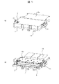
- FIG. 1 is an external perspective view of a power conversion device according to an embodiment of the present invention and a housing internal view with a housing cover removed.
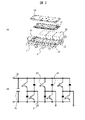
- 1 is an exploded perspective view and a block diagram of a power conversion device according to an embodiment of the present invention
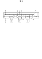
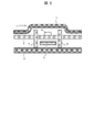
- FIG. 1 is a perspective view and a cross-sectional view along line AA of a peripheral portion of a magnetic sensor according to a first embodiment of the present invention
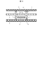
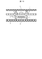
- FIG. 2 is a cross-sectional view of the peripheral portion of the magnetic sensor according to the first embodiment of the present invention
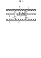
- FIG. 4 is an explanatory diagram of the distance between the housing and the magnetic body according to the first embodiment of the present invention; Sectional view of the peripheral part of the magnetic sensor according to the second embodiment of the present invention Sectional view of the peripheral part of the magnetic sensor according to the third embodiment of the present invention Sectional view of the peripheral part of the magnetic sensor according to the fourth embodiment of the present invention Cross-sectional view of the magnetic sensor peripheral portion according to the fifth embodiment of the present invention Sectional view of the peripheral part of the magnetic sensor according to the sixth embodiment of the present invention A diagram of a magnetic detection sensitivity correction unit according to a seventh embodiment of the present invention.
- FIG. 1 is an external perspective view of a power conversion device according to an embodiment of the present invention and a housing internal view with a housing cover removed.
- the housing 2a of the power converter includes a DC input terminal 22 for supplying a DC current to an inverter circuit housed inside the housing 2a, an AC conductor 6 for outputting AC current from the inverter to the outside, and an inverter circuit. It has a coolant inlet 21 for supplying a coolant to be cooled to the inside of the housing 2a, and a control signal input/output terminal 7 for transmitting a control signal for the inverter circuit to an external control device.
- the housing 2 at the bottom (base) of the housing 2a is a conductive member.
- a capacitor 25 for smoothing the input current input from the DC input terminal 22
- a main circuit section 24 for converting the DC current into an AC current
- a coolant channel for cooling the main circuit section 24.
- a magnetic detection substrate 8 for detecting the magnetic flux generated by the AC conductor 6, and a first housing 1 formed so as to cover the magnetic detection substrate 8 are accommodated.
- the first housing 1 is a conductive member.
- the magnetic detection substrate 8 has three magnetic sensors 5 (see FIG. 3) respectively corresponding to the AC conductors 6 for three phases, and is fixed to the second housing 2 with screws or the like.
- FIG. 2 is an exploded perspective view and block diagram of a power converter according to one embodiment of the present invention.
- a main circuit section 24 of the inverter circuit is composed of a DC input terminal 22 , a capacitor 25 , an IGBT element 26 , a diode element 27 and an AC conductor 6 .
- the capacitor 25 is connected in parallel with the positive and negative electrodes of the DC input terminal 22 .
- a portion that functions as a switching element by connecting the IGBT element 26 and the diode element 27 in series is connected in parallel with the capacitor 25 to form a half bridge circuit.
- the IGBT element 26 converts direct current to alternating current by being turned on or off based on a signal from a control circuit (not shown).
- Refrigerant passages 23 are provided on the upper and lower main surfaces of the main circuit portion 24 .
- a coolant such as a long-life coolant supplied from the outside through the coolant inlet 21 flows inside the coolant channel 23 .
- the coolant channel 23 has fins formed therein for improving cooling performance.
- the main circuit section 24 is sealed with an insulating resin in order to be insulated from the coolant channel 23 and the second housing 2 .
- the heat radiating surface of the main circuit portion 24 with which the coolant channel 23 is in contact is coated with heat radiating grease or the like to increase adhesion with the coolant channel 23 and reduce contact thermal resistance.
- the main circuit section 24 is configured by mounting an IGBT element 26 and a diode element 27 on a wiring material such as a printed circuit board.
- the main circuit section 24 and the capacitor 25 are electrically connected by a bonding material such as solder.
- the AC conductor 6 is electrically connected to the main circuit section 24 by screw fastening, soldering, or the like.
- FIG. 3 is a perspective view and a cross-sectional view along line AA of the peripheral portion of the magnetic sensor according to the first embodiment of the present invention.
- the output signal of the magnetic sensor 5 is transmitted from the control signal input/output terminal 7 to an inverter control circuit (not shown) outside the housing 2a via the wiring of the magnetic detection substrate 8.
- an inverter control circuit (not shown) outside the housing 2a via the wiring of the magnetic detection substrate 8.
- a power supply circuit for supplying electric power to the magnetic sensor 5 and the like are mounted on the magnetic detection substrate 8 . After passing through the lower surface of the magnetic sensor 5 , the AC conductor 6 protrudes toward the lower surface of the first housing 1 to prevent the magnetic flux of the motor current from interfering with electronic components other than the magnetic sensor 5 .
- the first magnetic body 3 and the second magnetic body 4 are formed longer than the magnetic sensor 5 in the horizontal direction of the drawing. As a result, it is possible to suppress the magnetic flux that wraps around from the left and right side surfaces of the first magnetic body 3 and the second magnetic body 4 .
- FIG. 4 is a cross-sectional view of FIG. 3(b) viewed from the R direction.
- the first magnetic body 3 and the second magnetic body 4 are constructed of an electromagnetic steel plate, a ferrite core, or the like, and are arranged at positions facing each other with an AC conductor (wiring) 6 and a magnetic sensor 5 interposed therebetween. .
- the first housing 1 covers one opening
- the second housing 2 covers the other opening. .
- the first magnetic body 3 and the second magnetic body 4 are fixed to through holes (not shown) provided in the magnetic detection substrate 8 .
- the positions of the magnetic bodies 3 and 4 are determined line-symmetrically from the centers of the magnetic sensor 5 and the AC conductor 6 by these through holes.
- a plurality of magnetic sensors 5 are arranged on the magnetic detection substrate 8 in the direction in which the first magnetic bodies 3 and the second magnetic bodies 4 are arranged. , are arranged above the AC conductors 6 of the respective phases.
- the magnetic sensor 5 reduces interference of external magnetic fluxes by detecting magnetic fluxes in the lateral direction of the paper surface. Moreover, the magnetic sensor 5 can increase the magnetic flux detection sensitivity by bringing it close to the AC conductor 6 .
- FIG. 5 is a cross-sectional view of the peripheral portion of the magnetic sensor according to the first embodiment of the present invention.
- the first housing 1 and the second housing 2 are made of a non-magnetic conductor such as aluminum, and are arranged so as to cover the opening of the space sandwiched between the first magnetic body 3 and the second magnetic body 4. .
- the magnetic flux 9 generated when the motor current 11 flows through the AC conductor 6 generates an induced current 10 in the first housing 1 and the second housing 2, and the magnetic flux resulting from this induced current 10 is generated by the motor. It interrupts the magnetic flux 9 caused by the current 11 .
- the magnetic bodies 3 and 4 are arranged only on the side of the magnetic sensor 5 between the AC conductors 6 of each phase, and no magnetic shield is provided in the height direction (vertical direction on the paper surface). This contributes to the reduction in thickness, while suppressing magnetic flux leakage from this space to other phases.
- the magnetic flux 9 of the motor current 11 flowing in the AC conductor 6 interferes with the other phase magnetic sensor 5 and the surrounding circuits without providing additional magnetic bodies on the upper surface of the magnetic sensor 5 and the lower surface of the AC conductor 6. can be suppressed. As a result, both the reduction in thickness of the power conversion device and the improvement in current detection accuracy are achieved. Furthermore, in this structure, since the magnetic bodies 3 and 4 for suppressing the leakage of the magnetic flux 9 and the housings 1 and 2 are separated respectively, the assembling efficiency is improved.
- the first housing 1 is arranged so as to cover the magnetic detection board 8 and serves as a fixed object when a control board (not shown) is arranged on the upper side, and also forms a wide case potential surface on the lower surface of the control board. to stabilize the potential of the control circuit.
- the AC conductor 6 is made of a conductor such as copper, and is electrically connected to the output terminal of the power module and the motor by welding or screwing. Also, the AC conductor 6 is fixed to the second housing 2 via an insulating material 28 . Therefore, the AC conductor 6 , the magnetic bodies 3 and 4 , and the magnetic sensor 5 are positioned relative to each other via the second housing 2 and the magnetic detection substrate 8 .
- FIG. 6 is an explanatory diagram of the distance between the housing and the magnetic body according to the first embodiment of the present invention.
- the thickness 12 in the arrangement direction of the first magnetic body 3 and the second magnetic body 4 is determined by the position ( It refers to the thickness of the edge of the magnetic material).
- a distance 13 from each end of the first magnetic body 3 or the second magnetic body 4 to the first housing 1 or the second housing 2 is It refers to the distance between the body 1 or the second housing 2 and the closest point.
- the magnetic bodies 3 and 4 are arranged so that the distance 13 is smaller than the thickness 12 of the ends of the magnetic bodies 3 and 4 .
- the shape of the central portions of the magnetic bodies 3 and 4 is not limited.
- the magnetic bodies 3 and 4 and the housings 1 and 2 may be in contact with each other.
- FIG. 7 is a cross-sectional view of the peripheral portion of the magnetic sensor according to the second embodiment of the present invention.
- the first housing 1 has a surface facing the second housing 2 while securing a space for the installation location of the electronic component 14, and the magnetic sensor 5, the first magnetic body 3, and the second magnetic body 4 are provided.
- the AC conductor 6 has a convex portion 1a on its upper surface.
- the respective ends of the first magnetic body 3 and the second magnetic body 4 are close to the first housing 1 due to the protrusion 1a. Since this is done, it is not necessary to increase the size of the first magnetic body 3 and the second magnetic body 4 when the electronic component 14 larger than the magnetic sensor 5 is mounted on the magnetic detection substrate 8 . Further, they are arranged so that the distance to the first housing 1 or the second housing 2 is smaller than the thickness 12 in the arrangement direction of the first magnetic bodies 3 and the second magnetic bodies 4 described above.
- FIG. 8 is a cross-sectional view of the periphery of a magnetic sensor according to a third embodiment of the invention.
- the first housing 1 has a concave portion 1b in the outward direction on the upper surfaces of the magnetic sensor 5, the first magnetic body 3, the second magnetic body 4, and the AC conductor 6. Since the side surfaces of the first magnetic body 3 and the second magnetic body 4 are covered with the first housing 1 by the concave portion 1b, the lateral It is possible to suppress the magnetic flux leaking to (in the horizontal direction of the paper surface).
- FIG. 9 is a cross-sectional view of the peripheral portion of the magnetic sensor according to the fourth embodiment of the present invention.
- the first magnetic body 3 and the second magnetic body 4 have magnetic body protrusions 15 on their facing surfaces.
- the magnetic protrusions 15 are formed so that extension lines of the respective protrusions are closer to the first housing 1 and the second housing 2 than the upper surface of the magnetic sensor 5 and the lower surface of the AC conductor 6 .
- FIG. 10 is a cross-sectional view of the peripheral portion of the magnetic sensor according to the fifth embodiment of the present invention.
- the first magnetic body 3 and the second magnetic body 4 have a magnetic protrusion 15, and are fixed to the magnetic detection substrate 8 by the magnetic protrusion 15, thereby determining the height position. Thereby, the relative positions of the first magnetic body 3 and the second magnetic body 4 and the magnetic sensor 5 can be determined with high accuracy.
- the magnetic bodies 3 and 4 can be fixed to the magnetic detection substrate 8 by applying an adhesive to the projections 15 of the first magnetic body 3 and the second magnetic body 4, respectively.
- a housing potential wiring (not shown) is arranged around a through hole 8a provided in the magnetic detection substrate 8 for inserting the first magnetic body 3 and the second magnetic body 4, and the first magnetic body 3 and the second magnetic body 4 are connected to each other.
- the potentials of the first magnetic body 3 and the second magnetic body 4 can be determined by soldering the magnetic body 4 to the housing potential wiring.
- FIG. 11 is a cross-sectional view of the peripheral portion of the magnetic sensor according to the sixth embodiment of the present invention.
- an AC wiring 6a is provided on the magnetic detection substrate 8 in place of the AC conductor 6 described above, and the motor current 11 is configured to flow through the AC wiring 6a.
- the magnetic detection substrate 8 by providing the AC wiring 6a on the back side of the surface on which the magnetic sensor 5 is mounted, the creepage distance 29 necessary for insulating the magnetic sensor 5 and the AC wiring 6a is secured.
- the magnetic sensor 5 and the AC wiring 6a can be brought close to each other. This improves the sensitivity with which the magnetic sensor 5 detects magnetic flux. Furthermore, since the positions of the AC wiring 6a and the magnetic sensor 5 are accurately determined, the detection accuracy of the magnetic sensor 5 is improved.
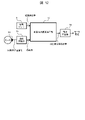
- FIG. 12 is a diagram of a magnetic detection sensitivity corrector according to the seventh embodiment of the present invention.
- the magnetic sensor 5 detects the magnetic flux of the motor current flowing through the AC conductor 6 and outputs the magnetic flux detection value to the magnetic flux detection sensitivity corrector 17 .
- the angle sensor 20 is connected to the rotor of the motor and outputs a rotor position signal to the speed converter 19 . Based on the rotor position signal input from the angle sensor 20 , the speed conversion unit 19 calculates the angular speed of the rotor of the motor to the magnetic flux detection sensitivity correction unit 17 . This angular velocity corresponds to the frequency of the motor current flowing through the AC conductor 6 .
- the magnetic flux detection sensitivity correction unit 17 and the speed conversion unit 19 are mounted in a control unit (not shown) outside the housing connected to the control signal input/output terminals in FIG.
- the relationship between the angular velocity of the rotor of the motor and the magnetic flux detection sensitivity of the magnetic sensor 5 is preset in the magnetic flux detection sensitivity correction unit 17 . Based on this relationship, the corrected magnetic flux detection value is calculated using the magnetic flux detection value input from the magnetic sensor 5 and the angular velocity input from the speed conversion unit 19 and output to the current calculation unit 18 .
- the current calculator 18 calculates a motor current from the input corrected magnetic flux detection value based on a preset relationship between the magnetic flux detection value and the motor current.
- the current calculator 18 is mounted in a controller outside the housing (not shown) connected to the control signal input/output terminal in FIG.
- the power converter includes an inverter circuit that converts direct current to alternating current, an alternating current conductor 6 that transmits alternating current, a magnetic sensor 5 that detects magnetism generated when alternating current flows through the alternating current conductor, It has a first magnetic body 3 and a second magnetic body 4 facing each other with an AC conductor 6 and a magnetic sensor 5 interposed therebetween, and a first housing 1 and a second housing 2 made of a conductive member.
- the first housing 1 covers one opening in the space sandwiched between the first magnetic body 3 and the second magnetic body 4, the second housing 2 covers the other opening of the space, and the first magnetic body 3 and the second magnetic body 4 are arranged so that the distance to the first housing 1 or the second housing 2 is smaller than the thickness of the first magnetic body 3 and the second magnetic body 4 in the arrangement direction. formed.
- the first housing 1 has a convex portion 1a formed so as to protrude toward the second housing 2 on the surface facing the second housing 2, and the convex portion 1a and the second housing
- a magnetic sensor 5 , a first magnetic body 1 , a second magnetic body 2 , and an AC conductor 6 are arranged between the body 2 .
- the first housing 1 has a concave portion 1b on the surface facing the second housing 2, which is recessed in a direction away from the second housing 2, and the concave portion 1b and the second housing 2
- a magnetic sensor 5, a first magnetic body, a second magnetic body, and an AC conductor 6 are arranged therebetween. By doing so, it is possible to suppress the magnetic flux leaking laterally (to the left and right of the drawing) from the gaps between the first magnetic body 3 and the second magnetic body 4 and the first housing 1 .
- the first magnetic body 3 and the second magnetic body 4 each have magnetic body protrusions 15 facing each other, and the extension lines of the respective protrusions of the magnetic body protrusions 15 are aligned with the upper surface of the magnetic sensor 5. It is formed closer to the first housing 1 and the second housing 2 than the lower surface of the AC conductor 6 . By doing so, the magnetic flux of the motor current flowing through the AC conductor 6 is induced to the magnetic protrusions 15, and the space or space sandwiched between the magnetic protrusions 15 of the first magnetic body 3 and the second magnetic body 4 is generated. Magnetic flux leaking from the opening to the surroundings is suppressed.
- the body 3 and the second magnetic body 4 are fixed to the magnetic detection substrate 8, respectively.
- a magnetic sensor 5 is arranged on the surface which is not exposed.
- a speed conversion unit 19 that converts the rotor position signal output from the angle sensor 20 connected to the rotor of the motor into an angular speed
- a magnetic flux detection sensitivity correction unit that corrects the magnetic flux detection value output by the magnetic sensor 5.
- the magnetic flux detection sensitivity correction unit 17 calculates the relationship between the magnetic flux detection value output from the magnetic sensor 5, the angular velocity output from the speed conversion unit 19, and the preset angular velocity and magnetic flux detection sensitivity. , to correct the magnetic flux detection value. By doing so, the change in the magnetic flux detection sensitivity of the magnetic sensor 5 that changes due to the induced current 10 generated in the first housing 1 and the second housing 2 is corrected, and the detection accuracy of the motor current is improved. can be made
- the present invention is not limited to the above embodiments, and various modifications and other configurations can be combined without departing from the scope of the invention. Moreover, the present invention is not limited to those having all the configurations described in the above embodiments, and includes those having some of the configurations omitted.
- first casing 1a convex portion 1b concave portion 2 second casing (base portion) 2a Inverter housing (whole) 3 First magnetic body 4 Second magnetic body 5 Magnetic sensor 6 AC conductor 6a AC conductor wiring 7 Control signal input/output terminal 8 Substrate for magnetic detection 8a Through hole 9 Magnetic flux 10 Induced current 11 Motor current 12 Thickness in arrangement direction 13 Magnetic body Distance 14 from end to housing Electronic component 15 Magnetic protrusion 17 Magnetic flux detection sensitivity correction unit 18 Current calculation unit 19 Speed conversion unit 20 Angle sensor 21 Refrigerant inlet 22 DC input terminal 23 Refrigerant channel 24 Main circuit unit 25 Capacitor 26 IGBT element 27 Diode element 28 Insulating material 29 Creepage distance
Landscapes
- Engineering & Computer Science (AREA)
- Power Engineering (AREA)
- Physics & Mathematics (AREA)
- Electromagnetism (AREA)
- Inverter Devices (AREA)
Abstract
Description
図1は、本発明の一実施形態に係る電力変換装置の外観斜視図と筐体カバーを外した筐体内部図である。
図7は、本発明の第2の実施形態に係る、磁気センサ周辺部の断面図である。
図8は、本発明の第3の実施形態に係る、磁気センサ周辺部の断面図である。
図9は、本発明の第4の実施形態に係る、磁気センサ周辺部の断面図である。
図10は、本発明の第5の実施形態に係る、磁気センサ周辺部の断面図である。
図11は、本発明の第6の実施形態に係る、磁気センサ周辺部の断面図である。
図12は、本発明の第7の実施形態に係る、磁気検出感度補正部についての図である。
1a 凸部
1b 凹部
2 第2筐体(ベース部分)
2a インバータ筐体(全体)
3 第1磁性体
4 第2磁性体
5 磁気センサ
6 交流導体
6a 交流導体配線
7 制御信号入出力端子
8 磁気検出用基板
8a 貫通孔
9 磁束
10 誘導電流
11 モータ電流
12 配列方向の厚み
13 磁性体端部と筐体までの距離
14 電子部品
15 磁性体凸部
17 磁束検出感度補正部
18 電流算出部
19 速度変換部
20 角度センサ
21 冷媒流入口
22 直流入力端子
23 冷媒流路
24 主回路部
25 コンデンサ
26 IGBT素子
27 ダイオード素子
28 絶縁材料
29 沿面距離
Claims (7)
- 直流電流を交流電流に変換するインバータ回路と、
前記交流電流を伝達する交流導体と、
前記交流電流が前記交流導体を流れたときに生じる磁気を検出する磁気センサと、
前記交流導体と前記磁気センサを挟んで対向する第1磁性体および第2磁性体と、
導電性部材で形成される第1筐体と第2筐体と、を備え、
前記第1筐体は、前記第1磁性体と前記第2磁性体に挟まれた空間において、一方の開口を覆い、
前記第2筐体は、前記空間の他方の開口を覆い、
前記第1磁性体と前記第2磁性体のそれぞれの端部は、前記第1筐体又は前記第2筐体までの距離が前記第1磁性体と前記第2磁性体の配列方向の厚みより小さくなるように形成されている
電力変換装置。 - 請求項1に記載の電力変換装置であって、
前記第1筐体は、前記第2筐体と対向する面に、前記第2筐体に向かって突出するように形成された凸部を有し、
前記凸部と前記第2筐体との間に、前記磁気センサと、前記第1磁性体と、前記第2磁性体と、前記交流導体と、を配置した
電力変換装置。 - 請求項1に記載の電力変換装置であって、
前記第1筐体は、前記第2筐体と対向する面に、前記第2筐体から離れる方向に凹んで形成された凹部を有し、
前記凹部と前記第2筐体との間に、前記磁気センサと、前記第1磁性体と、前記第2磁性体と、前記交流導体と、を配置した
電力変換装置。 - 請求項1に記載の電力変換装置であって、
前記第1磁性体と前記第2磁性体は、それぞれ互いに対向する磁性体凸部を有し、
前記磁性体凸部のそれぞれの凸部分の延長線は、前記磁気センサの上面と前記交流導体の下面よりも、前記第1筐体および前記第2筐体側に形成されている
電力変換装置。 - 請求項1に記載の電力変換装置であって、
前記磁気センサが配置された磁気検出用基板を備え、
前記第1磁性体と前記第2磁性体は、磁性体凸部を有し、
前記磁性体凸部は、前記第1磁性体と前記第2磁性体とを前記磁気検出用基板にそれぞれ固定させる
電力変換装置。 - 請求項1に記載の電力変換装置であって、
前記磁気センサが配置された磁気検出用基板を備え、
前記交流導体は、前記磁気検出用基板上に設けられた配線によって構成され、
前記磁気検出用基板において、前記交流導体が配置されない面に前記磁気センサが配置される
電力変換装置。 - 請求項1に記載の電力変換装置であって、
モータの回転子に接続された角度センサから出力される回転子位置信号を角速度に変換する速度変換部と、
前記磁気センサが出力する磁束検出値を補正する磁束検出感度補正部と、を備え、
前記磁束検出感度補正部は、前記磁気センサから出力される磁束検出値と、前記速度変換部から出力される角速度と、予め設定された角速度と磁束検出感度との関係と、に基づき前記磁束検出値を補正する
電力変換装置。
Priority Applications (3)
| Application Number | Priority Date | Filing Date | Title |
|---|---|---|---|
| CN202280032447.XA CN117280880B (zh) | 2021-07-14 | 2022-03-02 | 电力转换装置 |
| US18/564,819 US12506419B2 (en) | 2021-07-14 | 2022-03-02 | Power conversion device |
| DE112022001703.1T DE112022001703T5 (de) | 2021-07-14 | 2022-03-02 | Leistungsumwandlungsvorrichtung |
Applications Claiming Priority (2)
| Application Number | Priority Date | Filing Date | Title |
|---|---|---|---|
| JP2021-116682 | 2021-07-14 | ||
| JP2021116682A JP7623904B2 (ja) | 2021-07-14 | 2021-07-14 | 電力変換装置 |
Publications (1)
| Publication Number | Publication Date |
|---|---|
| WO2023286328A1 true WO2023286328A1 (ja) | 2023-01-19 |
Family
ID=84918820
Family Applications (1)
| Application Number | Title | Priority Date | Filing Date |
|---|---|---|---|
| PCT/JP2022/008994 Ceased WO2023286328A1 (ja) | 2021-07-14 | 2022-03-02 | 電力変換装置 |
Country Status (5)
| Country | Link |
|---|---|
| US (1) | US12506419B2 (ja) |
| JP (1) | JP7623904B2 (ja) |
| CN (1) | CN117280880B (ja) |
| DE (1) | DE112022001703T5 (ja) |
| WO (1) | WO2023286328A1 (ja) |
Families Citing this family (1)
| Publication number | Priority date | Publication date | Assignee | Title |
|---|---|---|---|---|
| JP2024165428A (ja) * | 2023-05-17 | 2024-11-28 | 株式会社豊田自動織機 | 電力供給システム |
Citations (5)
| Publication number | Priority date | Publication date | Assignee | Title |
|---|---|---|---|---|
| JP2005300170A (ja) * | 2004-04-06 | 2005-10-27 | Mitsubishi Electric Corp | 電流検出装置およびそれを備えた電力変換装置 |
| JP2005321206A (ja) * | 2004-05-06 | 2005-11-17 | Mitsubishi Electric Corp | 電流検出装置 |
| JP2013257294A (ja) * | 2012-06-14 | 2013-12-26 | Yazaki Corp | 電流センサ |
| JP2014219221A (ja) * | 2013-05-01 | 2014-11-20 | 富士通コンポーネント株式会社 | 電流センサ |
| JP2015049184A (ja) * | 2013-09-03 | 2015-03-16 | Tdk株式会社 | インバータ装置 |
Family Cites Families (19)
| Publication number | Priority date | Publication date | Assignee | Title |
|---|---|---|---|---|
| JP3471065B2 (ja) * | 1994-03-01 | 2003-11-25 | 株式会社フジタ | キャブタイヤケーブルの磁気シールド装置 |
| JP2003258477A (ja) * | 2002-02-27 | 2003-09-12 | Hitachi Metals Ltd | 磁気シールド装置 |
| JP2006013072A (ja) * | 2004-06-24 | 2006-01-12 | Ricoh Co Ltd | 電子装置 |
| US8482904B2 (en) * | 2010-05-25 | 2013-07-09 | Lear Corporation | Power module with current sensing |
| US20140184212A1 (en) * | 2011-08-31 | 2014-07-03 | Honda Motor Co., Ltd. | Current detection circuit module |
| JP6039356B2 (ja) * | 2012-10-22 | 2016-12-07 | 日立オートモティブシステムズ株式会社 | 電力変換装置 |
| JP6060664B2 (ja) * | 2012-12-13 | 2017-01-18 | 株式会社デンソー | 電源装置 |
| US20150173238A1 (en) * | 2013-12-18 | 2015-06-18 | Caterpillar Inc. | Configurable power converter package |
| JP2016100943A (ja) * | 2014-11-19 | 2016-05-30 | 株式会社ケーヒン | 電力変換装置 |
| WO2017217267A1 (ja) * | 2016-06-15 | 2017-12-21 | 株式会社デンソー | 電流センサ |
| JP6481672B2 (ja) * | 2016-10-11 | 2019-03-13 | Tdk株式会社 | 回転型磁気結合装置 |
| US10212838B2 (en) * | 2017-01-13 | 2019-02-19 | Cree Fayetteville, Inc. | High power multilayer module having low inductance and fast switching for paralleling power devices |
| JP2018191452A (ja) * | 2017-05-09 | 2018-11-29 | 矢崎総業株式会社 | 電気接続箱 |
| JPWO2019082364A1 (ja) * | 2017-10-26 | 2020-10-22 | 日産自動車株式会社 | 電力変換装置 |
| JP2021036200A (ja) * | 2017-12-13 | 2021-03-04 | アルプスアルパイン株式会社 | 電流センサ及び電流センサのケースの製造方法 |
| JP2019184355A (ja) * | 2018-04-06 | 2019-10-24 | 本田技研工業株式会社 | コアレス電流測定装置 |
| JP6908004B2 (ja) * | 2018-06-19 | 2021-07-21 | 株式会社デンソー | 電力変換装置 |
| JP7000572B2 (ja) * | 2018-07-04 | 2022-01-19 | 日立Astemo株式会社 | 電気回路装置 |
| JP6717347B2 (ja) * | 2018-07-25 | 2020-07-01 | 株式会社デンソー | 電力変換装置 |
-
2021
- 2021-07-14 JP JP2021116682A patent/JP7623904B2/ja active Active
-
2022
- 2022-03-02 CN CN202280032447.XA patent/CN117280880B/zh active Active
- 2022-03-02 WO PCT/JP2022/008994 patent/WO2023286328A1/ja not_active Ceased
- 2022-03-02 US US18/564,819 patent/US12506419B2/en active Active
- 2022-03-02 DE DE112022001703.1T patent/DE112022001703T5/de active Pending
Patent Citations (5)
| Publication number | Priority date | Publication date | Assignee | Title |
|---|---|---|---|---|
| JP2005300170A (ja) * | 2004-04-06 | 2005-10-27 | Mitsubishi Electric Corp | 電流検出装置およびそれを備えた電力変換装置 |
| JP2005321206A (ja) * | 2004-05-06 | 2005-11-17 | Mitsubishi Electric Corp | 電流検出装置 |
| JP2013257294A (ja) * | 2012-06-14 | 2013-12-26 | Yazaki Corp | 電流センサ |
| JP2014219221A (ja) * | 2013-05-01 | 2014-11-20 | 富士通コンポーネント株式会社 | 電流センサ |
| JP2015049184A (ja) * | 2013-09-03 | 2015-03-16 | Tdk株式会社 | インバータ装置 |
Also Published As
| Publication number | Publication date |
|---|---|
| DE112022001703T5 (de) | 2024-01-11 |
| CN117280880A (zh) | 2023-12-22 |
| CN117280880B (zh) | 2026-06-23 |
| US20240275297A1 (en) | 2024-08-15 |
| US12506419B2 (en) | 2025-12-23 |
| JP7623904B2 (ja) | 2025-01-29 |
| JP2023012919A (ja) | 2023-01-26 |
Similar Documents
| Publication | Publication Date | Title |
|---|---|---|
| US9479025B2 (en) | Drive device and electric power steering device including the drive device | |
| US9590553B2 (en) | Power conversion apparatus and electric power steering device | |
| KR20150036582A (ko) | 전력 변환 장치 | |
| US10263495B2 (en) | Rotary electric machine | |
| CN104752368B (zh) | 电子控制装置 | |
| JP6854936B1 (ja) | 回転電機 | |
| JP7140263B2 (ja) | 電力変換装置 | |
| CN107148731B (zh) | 电力转换装置 | |
| CN117296237A (zh) | 功率变换装置 | |
| US12506419B2 (en) | Power conversion device | |
| JP3856799B2 (ja) | 電力変換装置 | |
| NL2021196B1 (en) | Module and power conversion device | |
| WO2023053873A1 (ja) | パワーモジュール | |
| US20240244807A1 (en) | Electric power converter | |
| JP2015125042A (ja) | 電流検出器 | |
| JP2008206324A (ja) | インバータ発電機用電気回路ユニット | |
| JP6771835B2 (ja) | 電力変換装置 | |
| JP2023127605A (ja) | 端子カバー付き半導体スイッチ装置および電源システム | |
| JP2022035386A (ja) | 電子装置 | |
| JP2016100393A (ja) | 電子装置 | |
| JP2025165843A (ja) | 電流検出装置 | |
| JP2023080456A (ja) | 電流センサ及びそれを用いた電力変換装置 | |
| WO2020230552A1 (ja) | 配線基板 |
Legal Events
| Date | Code | Title | Description |
|---|---|---|---|
| 121 | Ep: the epo has been informed by wipo that ep was designated in this application |
Ref document number: 22841678 Country of ref document: EP Kind code of ref document: A1 |
|
| WWE | Wipo information: entry into national phase |
Ref document number: 202280032447.X Country of ref document: CN |
|
| WWE | Wipo information: entry into national phase |
Ref document number: 112022001703 Country of ref document: DE |
|
| WWE | Wipo information: entry into national phase |
Ref document number: 18564819 Country of ref document: US |
|
| 122 | Ep: pct application non-entry in european phase |
Ref document number: 22841678 Country of ref document: EP Kind code of ref document: A1 |