WO2023281958A1 - 車両用装置および車両制御方法 - Google Patents
車両用装置および車両制御方法 Download PDFInfo
- Publication number
- WO2023281958A1 WO2023281958A1 PCT/JP2022/022762 JP2022022762W WO2023281958A1 WO 2023281958 A1 WO2023281958 A1 WO 2023281958A1 JP 2022022762 W JP2022022762 W JP 2022022762W WO 2023281958 A1 WO2023281958 A1 WO 2023281958A1
- Authority
- WO
- WIPO (PCT)
- Prior art keywords
- vehicle
- sensor unit
- power supply
- sensor
- control
- Prior art date
- Legal status (The legal status is an assumption and is not a legal conclusion. Google has not performed a legal analysis and makes no representation as to the accuracy of the status listed.)
- Ceased
Links
Images


Classifications
-
- B—PERFORMING OPERATIONS; TRANSPORTING
- B60—VEHICLES IN GENERAL
- B60W—CONJOINT CONTROL OF VEHICLE SUB-UNITS OF DIFFERENT TYPE OR DIFFERENT FUNCTION; CONTROL SYSTEMS SPECIALLY ADAPTED FOR HYBRID VEHICLES; ROAD VEHICLE DRIVE CONTROL SYSTEMS FOR PURPOSES NOT RELATED TO THE CONTROL OF A PARTICULAR SUB-UNIT
- B60W30/00—Purposes of road vehicle drive control systems not related to the control of a particular sub-unit, e.g. of systems using conjoint control of vehicle sub-units
- B60W30/08—Active safety systems predicting or avoiding probable or impending collision or attempting to minimise its consequences
- B60W30/09—Taking automatic action to avoid collision, e.g. braking and steering
-
- B—PERFORMING OPERATIONS; TRANSPORTING
- B60—VEHICLES IN GENERAL
- B60W—CONJOINT CONTROL OF VEHICLE SUB-UNITS OF DIFFERENT TYPE OR DIFFERENT FUNCTION; CONTROL SYSTEMS SPECIALLY ADAPTED FOR HYBRID VEHICLES; ROAD VEHICLE DRIVE CONTROL SYSTEMS FOR PURPOSES NOT RELATED TO THE CONTROL OF A PARTICULAR SUB-UNIT
- B60W50/00—Details of control systems for road vehicle drive control not related to the control of a particular sub-unit, e.g. process diagnostic or vehicle driver interfaces
- B60W50/02—Ensuring safety in case of control system failures, e.g. by diagnosing, circumventing or fixing failures
- B60W50/023—Avoiding failures by using redundant parts
-
- B—PERFORMING OPERATIONS; TRANSPORTING
- B60—VEHICLES IN GENERAL
- B60W—CONJOINT CONTROL OF VEHICLE SUB-UNITS OF DIFFERENT TYPE OR DIFFERENT FUNCTION; CONTROL SYSTEMS SPECIALLY ADAPTED FOR HYBRID VEHICLES; ROAD VEHICLE DRIVE CONTROL SYSTEMS FOR PURPOSES NOT RELATED TO THE CONTROL OF A PARTICULAR SUB-UNIT
- B60W50/00—Details of control systems for road vehicle drive control not related to the control of a particular sub-unit, e.g. process diagnostic or vehicle driver interfaces
- B60W50/02—Ensuring safety in case of control system failures, e.g. by diagnosing, circumventing or fixing failures
- B60W50/029—Adapting to failures or work around with other constraints, e.g. circumvention by avoiding use of failed parts
-
- B—PERFORMING OPERATIONS; TRANSPORTING
- B60—VEHICLES IN GENERAL
- B60W—CONJOINT CONTROL OF VEHICLE SUB-UNITS OF DIFFERENT TYPE OR DIFFERENT FUNCTION; CONTROL SYSTEMS SPECIALLY ADAPTED FOR HYBRID VEHICLES; ROAD VEHICLE DRIVE CONTROL SYSTEMS FOR PURPOSES NOT RELATED TO THE CONTROL OF A PARTICULAR SUB-UNIT
- B60W50/00—Details of control systems for road vehicle drive control not related to the control of a particular sub-unit, e.g. process diagnostic or vehicle driver interfaces
- B60W50/04—Monitoring the functioning of the control system
-
- G—PHYSICS
- G01—MEASURING; TESTING
- G01S—RADIO DIRECTION-FINDING; RADIO NAVIGATION; DETERMINING DISTANCE OR VELOCITY BY USE OF RADIO WAVES; LOCATING OR PRESENCE-DETECTING BY USE OF THE REFLECTION OR RERADIATION OF RADIO WAVES; ANALOGOUS ARRANGEMENTS USING OTHER WAVES
- G01S13/00—Systems using the reflection or reradiation of radio waves, e.g. radar systems; Analogous systems using reflection or reradiation of waves whose nature or wavelength is irrelevant or unspecified
- G01S13/86—Combinations of radar systems with non-radar systems, e.g. sonar, direction finder
- G01S13/865—Combination of radar systems with lidar systems
-
- G—PHYSICS
- G01—MEASURING; TESTING
- G01S—RADIO DIRECTION-FINDING; RADIO NAVIGATION; DETERMINING DISTANCE OR VELOCITY BY USE OF RADIO WAVES; LOCATING OR PRESENCE-DETECTING BY USE OF THE REFLECTION OR RERADIATION OF RADIO WAVES; ANALOGOUS ARRANGEMENTS USING OTHER WAVES
- G01S13/00—Systems using the reflection or reradiation of radio waves, e.g. radar systems; Analogous systems using reflection or reradiation of waves whose nature or wavelength is irrelevant or unspecified
- G01S13/86—Combinations of radar systems with non-radar systems, e.g. sonar, direction finder
- G01S13/867—Combination of radar systems with cameras
-
- G—PHYSICS
- G01—MEASURING; TESTING
- G01S—RADIO DIRECTION-FINDING; RADIO NAVIGATION; DETERMINING DISTANCE OR VELOCITY BY USE OF RADIO WAVES; LOCATING OR PRESENCE-DETECTING BY USE OF THE REFLECTION OR RERADIATION OF RADIO WAVES; ANALOGOUS ARRANGEMENTS USING OTHER WAVES
- G01S13/00—Systems using the reflection or reradiation of radio waves, e.g. radar systems; Analogous systems using reflection or reradiation of waves whose nature or wavelength is irrelevant or unspecified
- G01S13/88—Radar or analogous systems specially adapted for specific applications
- G01S13/93—Radar or analogous systems specially adapted for specific applications for anti-collision purposes
- G01S13/931—Radar or analogous systems specially adapted for specific applications for anti-collision purposes of land vehicles
-
- G—PHYSICS
- G08—SIGNALLING
- G08G—TRAFFIC CONTROL SYSTEMS
- G08G1/00—Traffic control systems for road vehicles
- G08G1/16—Anti-collision systems
-
- B—PERFORMING OPERATIONS; TRANSPORTING
- B60—VEHICLES IN GENERAL
- B60W—CONJOINT CONTROL OF VEHICLE SUB-UNITS OF DIFFERENT TYPE OR DIFFERENT FUNCTION; CONTROL SYSTEMS SPECIALLY ADAPTED FOR HYBRID VEHICLES; ROAD VEHICLE DRIVE CONTROL SYSTEMS FOR PURPOSES NOT RELATED TO THE CONTROL OF A PARTICULAR SUB-UNIT
- B60W2420/00—Indexing codes relating to the type of sensors based on the principle of their operation
- B60W2420/40—Photo, light or radio wave sensitive means, e.g. infrared sensors
- B60W2420/403—Image sensing, e.g. optical camera
-
- B—PERFORMING OPERATIONS; TRANSPORTING
- B60—VEHICLES IN GENERAL
- B60W—CONJOINT CONTROL OF VEHICLE SUB-UNITS OF DIFFERENT TYPE OR DIFFERENT FUNCTION; CONTROL SYSTEMS SPECIALLY ADAPTED FOR HYBRID VEHICLES; ROAD VEHICLE DRIVE CONTROL SYSTEMS FOR PURPOSES NOT RELATED TO THE CONTROL OF A PARTICULAR SUB-UNIT
- B60W2420/00—Indexing codes relating to the type of sensors based on the principle of their operation
- B60W2420/40—Photo, light or radio wave sensitive means, e.g. infrared sensors
- B60W2420/408—Radar; Laser, e.g. lidar
-
- B—PERFORMING OPERATIONS; TRANSPORTING
- B60—VEHICLES IN GENERAL
- B60W—CONJOINT CONTROL OF VEHICLE SUB-UNITS OF DIFFERENT TYPE OR DIFFERENT FUNCTION; CONTROL SYSTEMS SPECIALLY ADAPTED FOR HYBRID VEHICLES; ROAD VEHICLE DRIVE CONTROL SYSTEMS FOR PURPOSES NOT RELATED TO THE CONTROL OF A PARTICULAR SUB-UNIT
- B60W2554/00—Input parameters relating to objects
- B60W2554/80—Spatial relation or speed relative to objects
- B60W2554/801—Lateral distance
-
- G—PHYSICS
- G01—MEASURING; TESTING
- G01S—RADIO DIRECTION-FINDING; RADIO NAVIGATION; DETERMINING DISTANCE OR VELOCITY BY USE OF RADIO WAVES; LOCATING OR PRESENCE-DETECTING BY USE OF THE REFLECTION OR RERADIATION OF RADIO WAVES; ANALOGOUS ARRANGEMENTS USING OTHER WAVES
- G01S13/00—Systems using the reflection or reradiation of radio waves, e.g. radar systems; Analogous systems using reflection or reradiation of waves whose nature or wavelength is irrelevant or unspecified
- G01S13/88—Radar or analogous systems specially adapted for specific applications
- G01S13/93—Radar or analogous systems specially adapted for specific applications for anti-collision purposes
- G01S13/931—Radar or analogous systems specially adapted for specific applications for anti-collision purposes of land vehicles
- G01S2013/9327—Sensor installation details
- G01S2013/93271—Sensor installation details in the front of the vehicles
-
- G—PHYSICS
- G01—MEASURING; TESTING
- G01S—RADIO DIRECTION-FINDING; RADIO NAVIGATION; DETERMINING DISTANCE OR VELOCITY BY USE OF RADIO WAVES; LOCATING OR PRESENCE-DETECTING BY USE OF THE REFLECTION OR RERADIATION OF RADIO WAVES; ANALOGOUS ARRANGEMENTS USING OTHER WAVES
- G01S13/00—Systems using the reflection or reradiation of radio waves, e.g. radar systems; Analogous systems using reflection or reradiation of waves whose nature or wavelength is irrelevant or unspecified
- G01S13/88—Radar or analogous systems specially adapted for specific applications
- G01S13/93—Radar or analogous systems specially adapted for specific applications for anti-collision purposes
- G01S13/931—Radar or analogous systems specially adapted for specific applications for anti-collision purposes of land vehicles
- G01S2013/9327—Sensor installation details
- G01S2013/93274—Sensor installation details on the side of the vehicles
Definitions
- Patent Literature 1 discloses a device that includes an integration unit that integrates sensor information from a plurality of sensors and that determines an abnormality in the integration unit. Patent document 1 also discloses that the reliability of the integration unit is ensured by redundancy.
- the present disclosure has been made based on this situation, and the object thereof is to provide a vehicle that can continue running even when a sensor or the like becomes abnormal while suppressing an increase in the number of components.
- An object of the present invention is to provide an apparatus for vehicle control and a vehicle control method.
- a vehicle device for use in a vehicle comprising: a first power supply unit; a second power supply; a first sensor unit operated by being supplied with electric power from the first power supply unit to detect an obstacle in front of the vehicle and to detect lateral position information, which is information relating to the position of the vehicle in the road width direction; a first control device that is powered by the first power supply unit and operates to control the vehicle based on the detection result of the first sensor unit; a second sensor unit that is powered by a second power supply unit and operates to detect a forward obstacle and lateral position information; and a second control device that is operated by being supplied with electric power from a second power supply unit and that controls the vehicle based on the detection result of the second sensor unit.
- This vehicle control method is A first power supply unit, a second power supply unit, and operated by being supplied with electric power from the first power supply unit to detect obstacles in front of the vehicle and lateral position information, which is information related to the position of the vehicle in the road width direction. and a second sensor unit operated by being supplied with electric power from a second power supply unit to detect a forward obstacle and lateral position information, and executed by a processor.
- a vehicle control method comprising: When the first power supply unit, the first sensor unit, the second power supply unit and the second sensor unit are normal, the detection results regarding the front obstacle are acquired from the first sensor unit and the second sensor unit respectively, and the front obstacle is detected.
- restriction control can be executed to continue vehicle travel while detecting forward obstacles and lateral position information. Even if one or more of the second sensor unit, the second control device, and the second power supply unit become abnormal, the first sensor unit, the first control device, and the first power supply unit perform limit control. can.
- first sensor unit, the second sensor unit, the first power supply unit, and the second power supply unit are normal, vertical integration processing for integrating the detection result of the first sensor unit and the detection result of the second sensor unit. and lateral direction integrated processing, high-precision vehicle control can also be performed.
- This vehicle control method uses either the first sensor section or the second sensor section even when the vehicle runs in the event of an abnormality. Therefore, it is possible to keep the vehicle running even in the event of an abnormality while suppressing an increase in the number of components.
- FIG. 5 is a view for explaining sensor mounting positions and fields of view 51L and 51L of the front-side millimeter-wave radar 50;
- FIG. 5 is a diagram for explaining an imaging range of a peripheral camera 60;
- FIG. 4 shows a sensor that can be used for the first sensor unit or the second sensor unit;
- FIG. 7 shows a portion of the sensor shown in FIG. 6;
- FIG. 4 is a diagram showing combinations of sensors that can be realized by the first sensor unit and the second sensor unit;
- FIG. 1 is a diagram showing the configuration of a vehicle device 10 according to the first embodiment.
- the vehicle device 10 is mounted on a vehicle C shown in FIG.
- the vehicle device 10 controls the steering and/or speed of the vehicle C without requiring, at least temporarily, driver intervention.
- the vehicle device 10 can execute automatic driving at level 3 of automatic driving. At autonomous driving level 3, the device performs all driving operations under limited conditions. However, in an emergency, the driver performs the driving operation.
- the vehicular device 10 may be capable of executing automatic driving levels other than automatic driving level 3, automatic driving levels 1, 2, 4, and the like.
- the vehicle C can run even when the vehicle device 10 does not function, that is, when the automatic driving level is zero.
- the vehicle device 10 includes two power supply units, a first power supply unit 21 and a second power supply unit 22, a plurality of sensors for detecting the situation around the vehicle C, and an ECU 70.
- the first power supply section 21 and the second power supply section 22 are power supply sections independent of each other. Both the first power supply unit 21 and the second power supply unit 22 can be charged with electric power generated by a generator mounted on the vehicle C. As shown in FIG.
- the first power supply unit 21 and the second power supply unit 22 can employ batteries using various materials such as lead-acid batteries, nickel-hydrogen secondary batteries, and lithium-ion secondary batteries.
- the plurality of sensors for detecting the situation around the vehicle C includes the front millimeter wave radar 30, the front camera 40, the front side millimeter wave radar 50, the peripheral camera 60;
- the forward millimeter-wave radar 30 irradiates millimeter waves as transmission waves in the field of view, and receives reflected waves generated by reflection of the transmission waves from objects.
- the front millimeter wave radar 30 detects the position and direction from the vehicle C to an external object based on the time difference between transmission and reception and the irradiation direction of the transmission wave.
- the field of view of the front millimeter wave radar 30 includes the front of the vehicle C, and the front millimeter wave radar 30 detects obstacles in front of the vehicle C.
- FIG. Obstacles include stationary objects and moving objects. An example of a moving object is a preceding vehicle traveling in the same lane as vehicle C.
- the mounting position of front millimeter wave radar 30 is, for example, the front end of vehicle C and the center in the vehicle width direction.
- An example of the viewing angle of the front millimeter-wave radar 30 is about ⁇ 60 degrees with the front of the vehicle C being 0 degrees.
- the front camera 40 is a monocular camera that captures the front of the vehicle C.
- the front camera 40 is used to detect lane boundaries.
- Lane boundaries define lane boundaries.
- An example of a lane boundary is the lane marking 8 shown in FIG.
- the road edge becomes the road boundary.
- the installation position of the front camera 40 is, for example, in the interior of the vehicle C and near the front end of the roof, as shown in FIG.
- the field of view of the front camera 40 is preferably a wide field of view of 100° or more so that the lane markings 8 can be detected in the vicinity of the vehicle C. However, since the lane markings 8 also extend forward along the vehicle C, the field of view may be narrower than 100 degrees.
- the front millimeter-wave radar 30 and the front camera 40 are the first sensor section that operates by being supplied with power from the first power supply section 21 .
- the front lateral millimeter wave radar 50 includes a left front lateral millimeter wave radar 50L and a right front lateral millimeter wave radar 50R.
- the left front side millimeter wave radar 50L and the right front side millimeter wave radar 50R are radars for detecting obstacles present on the left side and right side of the vehicle C, respectively.
- the left front side millimeter wave radar 50L is installed at the left front end of the vehicle C
- the right front side millimeter wave radar 50R is installed at the right front end of the vehicle C. Obstacles to the sides of the vehicle C must be detected over a wide range.
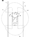
- FIG. 2 illustrates fields of view 51L and 51R of the front left lateral millimeter wave radar 50L and the right front lateral millimeter wave radar 50R.
- the left front side millimeter wave radar 50L and the right front side millimeter wave radar 50R each have a field of view front obliquely in front of the vehicle C. As shown in FIG.
- the front side millimeter wave radar 50 detects the position and direction from the vehicle C to an external object based on the time difference between transmission and reception of millimeter waves and the irradiation direction of the transmission wave.
- the field of view obtained by combining the two fields of view 51L and 51R includes the front of the vehicle C as well.
- the fields of view 51L and 51R are ⁇ 60° centered on the front direction of the left front lateral millimeter wave radar 50L and the right front lateral millimeter wave radar 50R.
- the peripheral cameras 60 include a front peripheral camera 60F, a left peripheral camera 60L, a right peripheral camera 60R, and a rear peripheral camera 60B.
- the front peripheral camera 60F is installed at the front end of the vehicle C and at the center in the vehicle width direction.
- the left peripheral camera 60L is installed on the lower surface of the left door mirror of the vehicle C.
- the right peripheral camera 60R is installed on the lower surface of the right door mirror of the vehicle C.
- the rear peripheral camera 60B is installed at the rear end of the vehicle C and at the center in the vehicle width direction.
- the four peripheral cameras 60 are provided for the purpose of coordinate-converting the images captured by these four peripheral cameras 60 to create a bird's-eye view image of the vehicle C viewed from above. Since it is a camera for this purpose, the range captured by the peripheral camera 60 is the periphery of the vehicle C. As shown in FIG. In other words, the imaging range of the peripheral camera 60 is closer to the vehicle C than the imaging range of the front camera 40 .
- FIG. 3 is a diagram for explaining the imaging range of the peripheral camera 60.
- the front peripheral camera 60F, the left peripheral camera 60L, the right peripheral camera 60R, and the rear peripheral camera 60B all have wide-angle fields of view. Therefore, the imaging range 61F of the front peripheral camera 60F, the imaging range 61L of the left peripheral camera 60L, the imaging range 61R of the right peripheral camera 60R, and the imaging range 61B of the rear peripheral camera 60B all correspond to the body of the vehicle C or its body. including the vicinity. Also, the shooting ranges 61F, 61L, 61R, and 61B partially overlap with two adjacent shooting ranges. Since the images of such photographing ranges 61F, 61L, 61R, and 61B are photographed, a bird's-eye view image can be created by subjecting the images photographed by the four peripheral cameras 60 to coordinate transformation.
- the front-side millimeter-wave radar 50 and the peripheral camera 60 are second sensor units that operate by being supplied with power from the second power supply unit 22 .
- the ECU 70 has two SoCs (System-on-a-chip) 71 and 72 .
- SoC 71 is a first control device
- SoC 72 is a second control device, each having a processor.
- SoCs 71 and 72 are configurations including processors, nonvolatile memories, RAMs, and bus lines connecting these configurations.
- the nonvolatile memory stores a vehicle control program executed by the processor.
- the SoCs 71 and 72 can each execute abnormal control, which will be described later, by the processor executing the program stored in the non-volatile memory while using the temporary storage function of the RAM.
- the SoC 71 and SoC 72 can also execute normal automatic operation control, which will be described later. Execution of these controls means execution of the vehicle control method corresponding to the program.
- the SoC 71 and SoC 72 are capable of executing the same control, but the power supplies are different from each other.
- the SoC 71 operates by being supplied with power from the first power supply unit 21 .
- the SoC 72 operates by receiving power from the second power supply unit 22 .
- Normal automatic operation control executed by the SoCs 71 and 72 will be described. Normal automatic operation control is executed by one of the SoC 71 and the SoC 72, which is set in advance. Below, it demonstrates that SoC71 performs automatic operation control at the time of normal.
- the normal automatic operation control is a control that is executed when the vehicle C is under automatic operation control and the SoC 71 has not detected an abnormality. Further, it is assumed that automatic driving control is control at automatic driving level 3.
- Fig. 4 shows the normal automatic operation control as a flow chart. Only S1 is executed by SoC 71 and SoC 72 together. SoCs 71 and 72 determine whether or not an abnormality has been detected. Targets for abnormality determination are the first power supply unit 21, the second power supply unit 22, the front millimeter wave radar 30, the front camera 40, the front side millimeter wave radar 50, the peripheral camera 60, the SoC 71, and the SoC 72.
- Either the SoC 71 or 72 can determine whether the front millimeter wave radar 30, the front camera 40, the front side millimeter wave radar 50, and the peripheral camera 60 are abnormal. Either the SoC 71 or 72 may determine whether the first power supply unit 21 or the second power supply unit 22 is abnormal. However, the SoC 72 that does not receive power supply from the first power supply unit 21 determines whether the first power supply unit 21 is abnormal, and the SoC 71 that does not receive power supply from the second power supply unit 22 determines whether the second power supply unit 22 is abnormal. It is preferable to determine whether The SoC 72 determines whether the SoC 71 is abnormal, and the SoC 71 determines whether the SoC 72 is abnormal.
- the power supply units 21 and 22 are abnormal means that the voltage within the specified range is not input. If disconnection, failure of the power supply units 21 and 22, or the like occurs, the voltage input to the ECU 70 falls below the prescribed range. Also, when a high voltage exceeding the specified range is input to the ECU 70, it is assumed that the power supply units 21 and 22 are abnormal. Whether or not front millimeter wave radar 30, front camera 40, front side millimeter wave radar 50, and peripheral camera 60 are abnormal is determined, for example, from the level of signals obtained from them. Of the SoCs 71 and 72, the side that is not executing normal automatic operation control is in a situation where control is not being executed, so the determination of whether there is an abnormality may be omitted.
- the SoC 71 advances the process to S2.
- the front millimeter wave radar 30, the front camera 40, the front side millimeter wave radar 50, and the peripheral camera 60 are controlled to acquire sensor signals from these sensors.
- the detection results regarding the forward obstacle are determined for each sensor. Also, lateral position information is determined for each sensor.
- the detection result regarding the forward obstacle includes the presence or absence of the forward obstacle and the position of the forward obstacle (in other words, the distance to the forward obstacle). Further, the size of the forward obstacle and the type of the forward obstacle may be included in the forward obstacle detection result.
- sensors used to detect forward obstacles are the front millimeter wave radar 30 and the front side millimeter wave radar 50 .
- the SoC 71 determines the detection result regarding the forward obstacle based on the sensor signals acquired from the front millimeter wave radar 30 and the front lateral millimeter wave radar 50 .
- the lateral position information is information regarding the position of the vehicle C in the road width direction.
- An example of the lateral position information is a lane boundary existing on the side of the vehicle C.
- sensors used to detect lateral position information are the front camera 40 and the peripheral camera 60 .
- the front camera 40 and the peripheral camera 60 can capture an image including the lane boundary existing on the side of the vehicle C.
- the SoC 71 detects lane markings 8 or road edges from images captured by the front camera 40 or the peripheral camera 60 by image processing.
- the detection result and lateral position information regarding the forward obstacle are obtained from the first sensor section and the second sensor section, respectively. Therefore, integration processing is executed in S4 and S5.
- the process executed in S4 is the vertical integration process
- the process executed in S5 is the horizontal integration process.
- the detection results regarding the forward obstacle determined for each sensor in S3 are integrated. For example, the position of the forward obstacle is determined by simple averaging or weighted averaging the positions of the forward obstacle determined for each sensor.
- the lateral position information determined for each sensor in S3 is integrated.
- the position of the forward obstacle is determined by simple averaging or weighted averaging the lane boundary positions determined for each sensor.
- the integration processing of S4 and S5 is sometimes called sensor fusion.
- the SoC 71 also calculates the distance in the road width direction from the vehicle C to the lane boundary. Since the front camera 40 and peripheral camera 60 have fixed installation positions and fixed fields of view, there is a one-to-one correspondence between road surface positions corresponding to arbitrary positions on the image. Therefore, if it is possible to determine where the lane boundary exists in the image captured by the front camera 40 or the peripheral camera 60, the distance in the road width direction from the vehicle C to the lane boundary can be calculated.
- the vertical and horizontal movements of vehicle C are determined.
- the longitudinal movement of the vehicle C is meant to determine its speed.
- the lateral movement of vehicle C is meant to determine the steering angle of vehicle C.
- SoC 71 may decide to slow vehicle C when the distance to a forward obstacle decreases.
- the SoC 71 may also decide to change the steering angle to follow the shape of the lane markings 8 .
- the SoC 71 can use various information such as route information to the destination in addition to the detection result and lateral position information regarding the forward obstacle. Then, the SoC 71 may decide to steer to change lanes when the distance to the forward obstacle becomes short or for a left or right turn.
- FIG. 5 shows the abnormal control.
- information requesting the driver to take over driving is output. This information may be images, sounds, or both. For example, a message requesting to take over driving is displayed on a display arranged at a position where the driver of vehicle C can visually recognize.
- limit control is performed with normal components.
- the restriction control is control for continuing the automatic control of the vehicle C without using the configuration in which the abnormality was detected in the process of S1.
- the component to which power is supplied from the power supply units 21 and 22 in which the abnormality is detected is not used either.
- the SoC 72, not the SoC 71 that receives power supply from the first power supply unit 21, executes limit control.
- limit control there are one or more fewer configurations that can be used compared to normal times. Therefore, limit control is less reliable than normal automatic operation control. Therefore, the limit control executes control that is more limited than the normal automatic operation control.
- functions can be restricted, such as prohibiting lane changes. If the lane change is prohibited, the lane keeping control is continued. It is also possible to limit the upper speed limit for automatic operation. It is also possible to limit the amount of time that automatic driving is allowed.
- the restriction control controls both the longitudinal direction and the lateral direction of the vehicle C to prevent contact with an obstacle in front and also to deviate from the lane in which it is traveling. It is possible to control the vehicle without A front millimeter-wave radar 30 and a front camera 40 are provided as a first sensor section that receives power from the first power supply section 21, and a front side millimeter-wave radar 50 and peripheral sensors are provided as a second sensor section that receives power supply from the first power supply section 21. A camera 60 is provided. Therefore, even if one of these sensors becomes abnormal, or even if either the first power supply section 21 or the second power supply section 22 becomes abnormal, vertical and horizontal control can be continued. be.
- the take-over time may be a fixed time, or a time that varies depending on the configuration that caused the abnormality, the type of road on which the vehicle is traveling, or the like.
- An example takeover time is, for example, 15 seconds. If the judgment result of S13 is NO, it will progress to S14.
- the handover completion condition can be the fact that the driver's grip on the steering wheel with both hands can be detected by an in-vehicle camera or the like.
- the condition for completion of handover may be detection that the driver has pressed a handover completion button prepared in advance.
- S13 determines whether the takeover time has elapsed during the limit control. If the determination in S13 is YES, that is, if the takeover time has elapsed during the limit control, the process proceeds to S16.
- the vehicle C is brought to an emergency stop. Even if the takeover time has not passed, the vehicle C may be brought to an emergency stop when an abnormality occurs in a part of the configuration.
- the front millimeter wave radar 30, the front camera 40, and the SoC 71 are connected to the first power supply unit 21, and the front side millimeter wave radar 50, the peripheral camera 60, and the SoC 72 are connected to the second power supply unit 22. are connected.
- both the longitudinal and lateral directions of the vehicle C are controlled to allow the vehicle to continue running.
- the front millimeter wave radar 30, the front camera 40, the SoC 71, and the first power supply unit 21 can be controlled in both the longitudinal direction and the lateral direction as the limit control (S12), and the vehicle can continue running.
- the front millimeter wave radar 30, the front camera 40, the front side millimeter wave radar 50, the peripheral camera 60, the first power supply unit 21, and the second power supply unit 22 are all normal, all the sensors are used for high accuracy detection. normal automatic operation control can be performed.
- the vehicle device 10 of the present embodiment is based on normal automatic driving control using all of the front millimeter wave radar 30, the front camera 40, the front side millimeter wave radar 50, and the peripheral camera 60.
- Limit control also uses the same sensor as normal automatic operation control. Therefore, while suppressing an increase in the number of components, the vehicle can continue to run by controlling both the vertical and horizontal directions even in the event of an abnormality.
- the vehicle device 10 includes a forward millimeter wave radar 30 and a forward camera 40 as first sensor units.
- the forward millimeter-wave radar 30 and the forward camera 40 are both front-system sensors, and are equipped for vehicle-to-vehicle distance control and lane keeping control even in vehicles that do not perform automatic driving level 3. Therefore, according to the configuration in which the front millimeter-wave radar 30 and the front camera 40 are used as the first sensor section, it becomes easy to add the second sensor section later and add the components constituting the vehicle device 10. .
- FIG. 6 shows sensors that can be used for the first sensor section or the second sensor section, including the sensors described in the first embodiment.
- the sensors with checkmarks for longitudinal control that is, V1 to V3 and VH
- the sensors with checkmarks for lateral control that is, H1 to H3 and VH
- the sensors with checkmarks for lateral control are sensors capable of detecting information necessary for lateral control of the vehicle C.
- the front millimeter wave radar 30 on the first line and the front side millimeter wave radar 50 on the second line have already been described in the first embodiment. These are sensors capable of detecting information necessary for longitudinal control of the vehicle C.
- FIG. The third line shows the Lidar 80 as a sensor capable of detecting information necessary for controlling the vehicle C in the longitudinal direction.
- FIG. 7 exemplifies the mounting position of the lidar 80 .
- the lidar 80 is mounted at the front end of the vehicle C and at the center in the width direction.
- the position of the lidar 80 is not limited to the position shown in FIG.
- the field of view of the lidar 80 may be the same field of view as the forward millimeter wave radar 30 .
- the field of view of the lidar 80 may be wider than the field of view of the front millimeter wave radar 30 , for example, the same field of view as the front camera 40 .
- the lidar 80 detects the position of an object by irradiating a field of view with laser light and receiving the reflected light of the laser light.
- the front camera 40 on the fourth line and the peripheral camera 60 on the fifth line in FIG. 6 have already been described in the first embodiment. These have been described as sensors capable of detecting information necessary for lateral control of the vehicle C.
- FIG. 1 The front camera 40 on the fourth line and the peripheral camera 60 on the fifth line in FIG. 6 have already been described in the first embodiment. These have been described as sensors capable of detecting information necessary for lateral control of the vehicle C.
- FIG. 1 The front camera 40 on the fourth line and the peripheral camera 60 on the fifth line in FIG. 6
- the sixth line shows the position detection sensor 90 as a sensor capable of detecting information necessary for controlling the vehicle C in the lateral direction.
- Position detection sensor 90 is used with map 91 .
- the position detection sensor 90 and the map 91 are illustrated in FIG.
- the position detection sensor 90 detects the current position of the vehicle C.
- a GNSS receiver is a specific example of the position detection sensor 90 .
- the position detection sensor 90 may be configured to sequentially detect the moving direction and moving distance of the vehicle C using an inertial sensor.
- the position detection sensor 90 may be configured by combining a GNSS receiver and an inertial sensor.
- the map 91 is digital map data that is stored in a predetermined storage memory and describes a road map that includes lane positions. All the digital map data may be stored in advance in the storage memory, or the data of the area determined by the current position of the vehicle C may be sequentially downloaded and stored.
- the ECU 70 functions as a position detection processing section 92 .
- the position detection processing unit 92 acquires a signal from the position detection sensor 90 and determines coordinates indicating the position of the vehicle C.
- FIG. Coordinates contain (x,y) information. Also, the coordinates may include height information.
- the position detection processing unit 92 uses the coordinates and the map 91 to sequentially determine the road width direction distance, which is the distance in the road width direction between the vehicle C and the road boundary closest to the vehicle C.
- Coordinates are an example of lateral position information because they contain (x, y) information. Using the lane positions contained in the map 91 along with the coordinates, the road width distance can be determined.
- the front camera 40 is shown on the 7th line in addition to the 4th line. However, in line 7, the distance detection processing unit 93 shown in FIG. 7 is used together with the front camera 40 . This allows both longitudinal and lateral control as shown in FIG.
- the distance detection processing unit 93 acquires image data captured by the front camera 40, which is a monocular camera, and calculates the distance to an object in the image from the image data. For example, the distance to the object is calculated using the fact that the shape of the blur differs before and after the focus position in the captured image. Also, for an object whose size can be specified or estimated, such as a vehicle, the distance can be calculated from the size shown in the image. Therefore, the distance to the forward obstacle can also be calculated, and longitudinal control becomes possible.
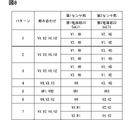
- FIG. 8 shows a sensor combination pattern that can be realized by the first sensor unit and the second sensor unit.
- the alphanumeric characters described in the "combination” column correspond to the alphanumeric characters shown in FIG.
- Each of the four or three sensors shown in “combination” includes two V's and two H's.
- the sensors shown in the "combination” are distributed to the first sensor section and the second sensor section such that one each of V and H is included.
- the first power supply unit 21 and SoC 71 are described in the row below the first sensor unit because power is supplied to the first sensor unit from the first power supply unit 21 and the SoC 71 is also the first power supply unit. It means that power is supplied from the power supply unit 21 .
- the second power supply unit 22 and SoC 72 are described in the row below the second sensor unit because power is supplied to the second sensor unit from the second power supply unit 22, and the SoC 72 is also supplied from the second power supply unit 22. Means that power is supplied.
- both the first sensor section and the second sensor section can be used to perform highly accurate normal automatic operation control.
- the first sensor unit includes the front side millimeter wave radar 50 and the front camera 40, and the second sensor unit includes the front millimeter wave radar 30 and the peripheral camera 60. Combining these will result in the same combination of sensors as in the first embodiment. Therefore, the combination in the second row of pattern 1 can perform the same normal automatic operation control as in the first embodiment.
- the first sensor unit includes the front side millimeter wave radar 50 and the front camera 40
- the second sensor unit includes the lidar 80, the position detection sensor 90 and the map 91.
- the first sensor section is the same as the first sensor section of the first embodiment. Therefore, it becomes easy to add the second sensor unit later and add a configuration that configures the vehicle device 10 .
- the first sensor unit since the first sensor unit has the front millimeter wave radar 30 and the second sensor unit has the lidar 80, the front millimeter wave radar 30 and the lidar 80 are used in normal automatic operation control. High-precision longitudinal control becomes possible.
- the second row of pattern 2 is the same as the first row of pattern 2 when the first sensor unit and the second sensor unit are combined. Therefore, as in the first line of Pattern 2, highly accurate longitudinal control using the forward millimeter wave radar 30 and the Lidar 80 is possible in normal automatic operation control.
- the first sensor unit includes the front side millimeter wave radar 50 and the front camera 40
- the second sensor unit includes the lidar 80 and the peripheral camera 60.
- the first sensor section is the same as the first sensor section of the first embodiment. Therefore, it becomes easy to add the second sensor unit later and add a configuration that configures the vehicle device 10 . Further, in the normal automatic operation control, highly accurate longitudinal control using the front millimeter wave radar 30 and the lidar 80 becomes possible.
- the second row of pattern 3 is the same as the first row of pattern 3 when the first sensor unit and the second sensor unit are combined. Therefore, even with this pattern, high-precision longitudinal control using the front millimeter-wave radar 30 and the lidar 80 is possible in normal automatic operation control.
- the first sensor unit is configured with the front camera 40 and the distance detection processing unit 93
- the second sensor unit is configured with the Lidar 80, the position detection sensor 90, and the map 91.
- the first sensor unit is configured with the front camera 40 and the distance detection processing unit 93
- the second sensor unit is also configured with the front camera 40 and the distance detection processing unit 93.
- both are VH.
- VH1 and VH2 they are indicated as VH1 and VH2 to indicate that they are different components.
- the front camera 40 included in the first sensor section is a first front camera
- the front camera 40 included in the second sensor section is a second front camera.
- Pattern 6 is a configuration in which the first sensor unit includes the front camera 40 and the distance detection processing unit 93 , and a configuration in which the second sensor unit includes the front side millimeter wave radar 50 and the peripheral camera 60 .
- the first sensor section includes the front and side millimeter wave radar 50 and the front camera 40
- the second sensor section includes the front and side millimeter wave radar 50, the position detection sensor 90, and the map 91. be.
- the first sensor section is the same as the first sensor section of the first embodiment. Therefore, it becomes easy to add the second sensor unit later and add a configuration that configures the vehicle device 10 .
- the first sensor unit includes the front side millimeter wave radar 50 and the front camera 40, and the second sensor unit includes the front millimeter wave radar 30, the position detection sensor 90 and the map 91.
- the second row of pattern 7 is the same as the first row of pattern 7 when the first sensor section and the second sensor section are combined.
- both SoC 71 and SoC 72 are capable of executing normal automatic operation control.
- only one of the SoC 71 and SoC 72 may be capable of executing normal automatic operation control.
- ⁇ Modification 2> when no abnormality is detected (S1: NO), vertical integration processing (S4) and horizontal integration processing (S5) are executed. However, either one of S4 and S5 may be omitted, and only one of the vertical integration process and the horizontal integration process may be executed.
- SoCs 71 and 72 described in the present disclosure are controllers described below.
- This controller and its techniques may be implemented by a special purpose computer comprising a processor programmed to perform one or more functions embodied by a computer program.
- the controller and techniques described in this disclosure may be implemented by dedicated hardware logic circuitry.
- the controller and techniques described in this disclosure may be implemented by one or more dedicated computers configured by a combination of a processor executing a computer program and one or more hardware logic circuits.
- Hardware logic circuits are, for example, ASICs and FPGAs.
- the storage medium for storing the computer program is not limited to the ROM, and may be stored in a computer-readable, non-transitional tangible recording medium as instructions executed by the computer.
- the program may be stored in a flash memory.
Landscapes
- Engineering & Computer Science (AREA)
- Radar, Positioning & Navigation (AREA)
- Remote Sensing (AREA)
- Automation & Control Theory (AREA)
- Physics & Mathematics (AREA)
- General Physics & Mathematics (AREA)
- Computer Networks & Wireless Communication (AREA)
- Mechanical Engineering (AREA)
- Transportation (AREA)
- Human Computer Interaction (AREA)
- Electromagnetism (AREA)
- Traffic Control Systems (AREA)
- Control Of Driving Devices And Active Controlling Of Vehicle (AREA)
Priority Applications (3)
| Application Number | Priority Date | Filing Date | Title |
|---|---|---|---|
| DE112022003481.5T DE112022003481T5 (de) | 2021-07-09 | 2022-06-06 | Fahrzeugvorrichtung und fahrzeugsteuerungsverfahren |
| CN202280044293.6A CN117561191A (zh) | 2021-07-09 | 2022-06-06 | 车辆用装置以及车辆控制方法 |
| US18/405,586 US12559114B2 (en) | 2021-07-09 | 2024-01-05 | Vehicle device and vehicle control method |
Applications Claiming Priority (2)
| Application Number | Priority Date | Filing Date | Title |
|---|---|---|---|
| JP2021-114258 | 2021-07-09 | ||
| JP2021114258A JP7746712B2 (ja) | 2021-07-09 | 2021-07-09 | 車両用装置および車両制御方法 |
Related Child Applications (1)
| Application Number | Title | Priority Date | Filing Date |
|---|---|---|---|
| US18/405,586 Continuation US12559114B2 (en) | 2021-07-09 | 2024-01-05 | Vehicle device and vehicle control method |
Publications (1)
| Publication Number | Publication Date |
|---|---|
| WO2023281958A1 true WO2023281958A1 (ja) | 2023-01-12 |
Family
ID=84800250
Family Applications (1)
| Application Number | Title | Priority Date | Filing Date |
|---|---|---|---|
| PCT/JP2022/022762 Ceased WO2023281958A1 (ja) | 2021-07-09 | 2022-06-06 | 車両用装置および車両制御方法 |
Country Status (5)
| Country | Link |
|---|---|
| US (1) | US12559114B2 (https=) |
| JP (1) | JP7746712B2 (https=) |
| CN (1) | CN117561191A (https=) |
| DE (1) | DE112022003481T5 (https=) |
| WO (1) | WO2023281958A1 (https=) |
Families Citing this family (3)
| Publication number | Priority date | Publication date | Assignee | Title |
|---|---|---|---|---|
| US12539775B2 (en) * | 2023-10-25 | 2026-02-03 | Honda Motor Co., Ltd. | Battery management for personal transport device based on prosocial behavior |
| GB202318254D0 (en) * | 2023-11-29 | 2024-01-10 | Agco Int Gmbh | Agricultural vehicles including an imaging controller, and related methods |
| CN118397582A (zh) * | 2024-04-19 | 2024-07-26 | 北京地平线信息技术有限公司 | 冗余感知方法、装置、电子设备和存储介质 |
Citations (4)
| Publication number | Priority date | Publication date | Assignee | Title |
|---|---|---|---|---|
| JP2019152896A (ja) * | 2018-02-28 | 2019-09-12 | 本田技研工業株式会社 | 走行制御装置、走行制御方法およびプログラム |
| US20200064483A1 (en) * | 2017-04-28 | 2020-02-27 | SZ DJI Technology Co., Ltd. | Sensing assembly for autonomous driving |
| JP2020037387A (ja) * | 2018-06-29 | 2020-03-12 | アプティブ・テクノロジーズ・リミテッド | 自動車アプリケーションのための電力およびデータセンタ(PDC:power and data center) |
| JP2020040545A (ja) * | 2018-09-11 | 2020-03-19 | 本田技研工業株式会社 | 車両用制御システムおよび車両の制御方法 |
Family Cites Families (12)
| Publication number | Priority date | Publication date | Assignee | Title |
|---|---|---|---|---|
| WO2011140993A1 (zh) * | 2010-05-12 | 2011-11-17 | 北京星河易达科技有限公司 | 基于综合状态检测的智能交通安全系统及其决策方法 |
| JP2017165296A (ja) * | 2016-03-17 | 2017-09-21 | 株式会社日立製作所 | 自動運転制御システム |
| WO2018173561A1 (ja) * | 2017-03-23 | 2018-09-27 | 日立オートモティブシステムズ株式会社 | 車両制御装置 |
| JP7018330B2 (ja) * | 2018-02-15 | 2022-02-10 | 本田技研工業株式会社 | 車両制御装置 |
| US11498614B2 (en) * | 2018-03-13 | 2022-11-15 | Hitachi Astemo, Ltd. | Control device for on-board device |
| JP7027279B2 (ja) * | 2018-08-07 | 2022-03-01 | 本田技研工業株式会社 | 車両制御装置、車両制御方法、およびプログラム |
| JP7076348B2 (ja) * | 2018-09-20 | 2022-05-27 | 日立Astemo株式会社 | 電子制御装置 |
| DE102018220063A1 (de) * | 2018-11-22 | 2020-05-28 | Robert Bosch Gmbh | Betriebsverfahren für eine redundante Sensoranordnung eines Fahrzeugsystems und korrespondierende redundante Sensoranordnung |
| DE102018220054A1 (de) * | 2018-11-22 | 2020-05-28 | Robert Bosch Gmbh | Betriebsverfahren für eine redundante Sensoranordnung eines Fahrzeugsystems und korrespondierende redundante Sensoranordnung |
| DE102018220605B4 (de) * | 2018-11-29 | 2024-04-18 | Audi Ag | Kraftfahrzeugnetzwerk und Verfahren zum Betreiben eines Kraftfahrzeugnetzwerks |
| DE102019130036A1 (de) * | 2019-11-07 | 2021-05-12 | Daimler Ag | Vorrichtung zur Steuerung eines automatisierten Fahrbetriebs eines Fahrzeugs |
| JP2021114258A (ja) | 2020-01-21 | 2021-08-05 | 京セラドキュメントソリューションズ株式会社 | 遠隔操作システムおよび情報処理装置 |
-
2021
- 2021-07-09 JP JP2021114258A patent/JP7746712B2/ja active Active
-
2022
- 2022-06-06 DE DE112022003481.5T patent/DE112022003481T5/de active Pending
- 2022-06-06 CN CN202280044293.6A patent/CN117561191A/zh active Pending
- 2022-06-06 WO PCT/JP2022/022762 patent/WO2023281958A1/ja not_active Ceased
-
2024
- 2024-01-05 US US18/405,586 patent/US12559114B2/en active Active
Patent Citations (4)
| Publication number | Priority date | Publication date | Assignee | Title |
|---|---|---|---|---|
| US20200064483A1 (en) * | 2017-04-28 | 2020-02-27 | SZ DJI Technology Co., Ltd. | Sensing assembly for autonomous driving |
| JP2019152896A (ja) * | 2018-02-28 | 2019-09-12 | 本田技研工業株式会社 | 走行制御装置、走行制御方法およびプログラム |
| JP2020037387A (ja) * | 2018-06-29 | 2020-03-12 | アプティブ・テクノロジーズ・リミテッド | 自動車アプリケーションのための電力およびデータセンタ(PDC:power and data center) |
| JP2020040545A (ja) * | 2018-09-11 | 2020-03-19 | 本田技研工業株式会社 | 車両用制御システムおよび車両の制御方法 |
Also Published As
| Publication number | Publication date |
|---|---|
| CN117561191A (zh) | 2024-02-13 |
| JP2023010252A (ja) | 2023-01-20 |
| DE112022003481T5 (de) | 2024-05-16 |
| US20240140450A1 (en) | 2024-05-02 |
| JP7746712B2 (ja) | 2025-10-01 |
| US12559114B2 (en) | 2026-02-24 |
Similar Documents
| Publication | Publication Date | Title |
|---|---|---|
| US11112804B2 (en) | Autonomous driving control apparatus and program product | |
| US10676093B2 (en) | Vehicle control system, vehicle control method, and storage medium | |
| RU2734643C1 (ru) | Способ помощи при парковке для устройства помощи при парковке и устройство помощи при парковке | |
| US9809223B2 (en) | Driving assistant for vehicles | |
| CN111226267B (zh) | 驾驶辅助车辆的行驶控制方法及行驶控制装置 | |
| WO2023281958A1 (ja) | 車両用装置および車両制御方法 | |
| US9896098B2 (en) | Vehicle travel control device | |
| EP3215400B1 (en) | Method for operating a driver assistance system of a motor vehicle, driver assistance system and motor vehicle | |
| US12071150B2 (en) | Vehicular driving assist system using forward viewing camera | |
| RU2729330C1 (ru) | Способ помощи при парковке и устройство помощи при парковке | |
| US20180162390A1 (en) | Vehicle Control Device and Vehicle Control Method | |
| JP6878196B2 (ja) | 位置推定装置 | |
| US20180265083A1 (en) | Collision avoidance device | |
| US20240383479A1 (en) | Vehicular sensing system with lateral threat assessment | |
| US20210370832A1 (en) | Data processing methods, devices, and apparatuses, and movable platforms | |
| CN113479205B (zh) | 移动体控制装置、移动体以及移动体控制方法 | |
| JP7056379B2 (ja) | 車両用走行制御装置 | |
| CN115257790B (zh) | 传感器异常推定装置 | |
| JP7444123B2 (ja) | データ補正装置、データ補正方法、データ補正プログラム及び車両 | |
| JP2022181582A (ja) | 駐車支援装置及び駐車支援方法 | |
| WO2016194135A1 (ja) | 車両制御装置及び車両制御方法 | |
| JP7798630B2 (ja) | 制御装置、制御方法、およびプログラム | |
| US20260004447A1 (en) | Display device | |
| JP2022182799A (ja) | 駐車支援装置及び駐車支援方法 | |
| JP2022154051A (ja) | 車載カメラセンサの異常検出装置 |
Legal Events
| Date | Code | Title | Description |
|---|---|---|---|
| 121 | Ep: the epo has been informed by wipo that ep was designated in this application |
Ref document number: 22837377 Country of ref document: EP Kind code of ref document: A1 |
|
| WWE | Wipo information: entry into national phase |
Ref document number: 202280044293.6 Country of ref document: CN |
|
| 122 | Ep: pct application non-entry in european phase |
Ref document number: 22837377 Country of ref document: EP Kind code of ref document: A1 |