WO2023248945A1 - ワイヤハーネス - Google Patents
ワイヤハーネス Download PDFInfo
- Publication number
- WO2023248945A1 WO2023248945A1 PCT/JP2023/022410 JP2023022410W WO2023248945A1 WO 2023248945 A1 WO2023248945 A1 WO 2023248945A1 JP 2023022410 W JP2023022410 W JP 2023022410W WO 2023248945 A1 WO2023248945 A1 WO 2023248945A1
- Authority
- WO
- WIPO (PCT)
- Prior art keywords
- electric wire
- adhesive layer
- grommet
- wire harness
- attached
- Prior art date
- Legal status (The legal status is an assumption and is not a legal conclusion. Google has not performed a legal analysis and makes no representation as to the accuracy of the status listed.)
- Ceased
Links
Images



Classifications
-
- B—PERFORMING OPERATIONS; TRANSPORTING
- B60—VEHICLES IN GENERAL
- B60R—VEHICLES, VEHICLE FITTINGS, OR VEHICLE PARTS, NOT OTHERWISE PROVIDED FOR
- B60R16/00—Electric or fluid circuits specially adapted for vehicles and not otherwise provided for; Arrangement of elements of electric or fluid circuits specially adapted for vehicles and not otherwise provided for
- B60R16/02—Electric or fluid circuits specially adapted for vehicles and not otherwise provided for; Arrangement of elements of electric or fluid circuits specially adapted for vehicles and not otherwise provided for electric constitutive elements
-
- H—ELECTRICITY
- H02—GENERATION; CONVERSION OR DISTRIBUTION OF ELECTRIC POWER
- H02G—INSTALLATION OF ELECTRIC CABLES OR LINES, OR OF COMBINED OPTICAL AND ELECTRIC CABLES OR LINES
- H02G3/00—Installations of electric cables or lines or protective tubing therefor in or on buildings, equivalent structures or vehicles
- H02G3/22—Installations of cables or lines through walls, floors or ceilings, e.g. into buildings
-
- Y—GENERAL TAGGING OF NEW TECHNOLOGICAL DEVELOPMENTS; GENERAL TAGGING OF CROSS-SECTIONAL TECHNOLOGIES SPANNING OVER SEVERAL SECTIONS OF THE IPC; TECHNICAL SUBJECTS COVERED BY FORMER USPC CROSS-REFERENCE ART COLLECTIONS [XRACs] AND DIGESTS
- Y02—TECHNOLOGIES OR APPLICATIONS FOR MITIGATION OR ADAPTATION AGAINST CLIMATE CHANGE
- Y02A—TECHNOLOGIES FOR ADAPTATION TO CLIMATE CHANGE
- Y02A30/00—Adapting or protecting infrastructure or their operation
- Y02A30/14—Extreme weather resilient electric power supply systems, e.g. strengthening power lines or underground power cables
Definitions
- the present invention relates to a wire harness.
- a wire harness having an outer conductor for shielding electromagnetic waves is well known.
- the outer conductor has a substantially cylindrical conductor tube made of aluminum, for example.
- Conductor tubes made of aluminum have high rigidity. Therefore, if the mounting space is narrow, the wire harness may not be able to be placed because the conductor tube limits the position.
- Patent Document 2 discloses a wire harness using a braided shield.
- This wire harness has a water stop valve that fills the gap between the electric wire and the grommet.
- the braided shield is arranged to cover the outer periphery of the water stopcock.
- a waterproof adhesive member is attached to the outer peripheral surface of the braided shield.
- the braided shield is flexible. Therefore, if the mounting space is narrow, the wire harness can be bent and placed. Therefore, if the wire harness of Patent Document 2 is adopted, the wire harness can be mounted even if the mounting space is narrow.
- An object of the present disclosure is to provide a wire harness that can improve water-stopping properties.
- a wire harness that solves the above problem includes an electric wire for transmitting electricity, a grommet that is attached to an opening through which the electric wire is passed, and in which the electric wire is housed, and a grommet that is provided for water-stopping the inside of the grommet.
- a water stop valve through which the electric wire is attached a shield material attached around the water stop valve, and a shield material attached to the outer periphery of the shield material, so that the shield material is tightly attached to the water stop valve.
- a second adhesion layer that is attached to the outer periphery of the first adhesion layer to make the first adhesion layer adhere to the shield material.
- the present disclosure can improve the water-stopping properties of a wire harness.
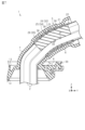
- FIG. 1 is a perspective view of the wire harness.
- FIG. 2 is a front view of the wire harness.
- FIG. 3 is an exploded perspective view of the wire harness.
- FIG. 4 is a cross-sectional view taken along the line IV--IV shown in FIG.
- FIG. 5 is a sectional view taken along the line VV shown in FIG.
- FIGS. 6(a) to 6(d) are procedural diagrams showing the flow of manufacturing a wire harness.
- FIG. 7 is an operational diagram of the wire harness.
- FIGS. 8(a) to 8(d) are procedural diagrams showing the flow of manufacturing a wire harness.
- the first adhesive layer brings the shield material into close contact with the water stopcock
- the second adhesive layer brings the first adhesive layer into close contact with the shield material.
- the grommet includes an assembly including the water stopcock, the electric wire, the shield material, the first adhesive layer, and the second adhesive layer inside. It has a cylindrical portion to accommodate the cylindrical portion, and a seat portion that supports the base end of the cylindrical portion. According to this configuration, the wire harness can easily undergo a shape change in which the cylindrical portion is bent from the seat portion. Therefore, it becomes possible to make the wire harness easy to bend.
- the grommet 5 is disposed, for example, at a portion of the attachment point 3 that separates indoor and outdoor areas.
- the tubular portion 6 of the grommet 5 is disposed on the indoor side, and the seat portion 8 is disposed on the outdoor side.
- the proximal end 7 of the grommet 5 is provided with a recess 7a that facilitates bending of the grommet 5.
- the assembly 22 includes, for example, a water stopcock 23, a shield material 24, a first adhesive layer 25, and a second adhesive layer 26.
- the assembly 22 is housed in the cylindrical portion 6 of the grommet 5. The assembly 22 prevents fluids such as water from entering the grommet 5.
- the second adhesion layer 26 is attached to the outer periphery of the first adhesion layer 25 to bring the first adhesion layer 25 into close contact with the shield material 24 .
- the second adhesive layer 26 is, for example, a tape 35 wound a plurality of times while shifting its position along the axial direction of the electric wire 2 (Z-axis direction in FIG. 5).
- the tape 35 preferably has high flexibility, high insulation, heat resistance, and cold resistance.
- the tape 35 is, for example, a vinyl tape.
- the grommet 5 has an annular seal portion 38 on its inner surface that seals the gap between the grommet 5 and the second adhesive layer 26.
- a plurality of seal portions 38 are formed at equal intervals along the axial direction of the electric wire 2 (Z-axis direction in FIG. 5).
- the seal portion 38 is, for example, a protrusion that protrudes from the inner surface of the grommet 5 by a predetermined amount.
- the seal portion 38 is, for example, a lip-type seal that assumes a sealed state by elastically deforming.
- the mounting space for the wire harness 1 may be small.
- an example is given in which the height of the mounting space is low.
- the wire harness 1 can be bent and arranged.
- the first adhesion layer 25 and the second adhesion layer 26 are also bendable, bending of the wire harness 1 is facilitated. In this way, it is possible to have flexibility in the posture (tilt) of the wire harness 1, so even if the mounting space is small, the wire harness 1 can be arranged.
- the first adhesive layer 25 tightly adheres to the shield material 24 by wrapping the second adhesive layer 26 around it. That is, in order to prevent a gap from forming between the shield material 24 and the first adhesive layer 25, the second adhesive layer 26 is wrapped around the outer periphery of the first adhesive layer 25. Therefore, the water-stopping property between the shield material 24 and the first adhesive layer 25 is further improved.
- the first adhesive layer 25 brings the shield material 24 into close contact with the water stopcock 23 and the second adhesive layer 26 brings the first adhesive layer 25 into close contact with the shield material 24.
- the two layers, the first adhesion layer 25 and the second adhesion layer 26, bring the members into close contact with each other, it is possible to make it difficult to create gaps between the members. Therefore, in the bendable wire harness 1, water-stopping properties can be improved.
- the grommet 5 has an annular seal portion 38 on its inner surface that seals the gap between the grommet 5 and the second adhesive layer 26 . According to this configuration, the water-stopping property between the grommet 5 and the second adhesive layer 26 can be improved.
- the second adhesive layer 26 is not limited to the tape 35, and may be, for example, a cylindrical member that covers the first adhesive layer 25 from the periphery.
- the stopcock 23 is not limited to a rubber stopper, but may be made of an elastic material. In this way, the stopcock 23 only needs to be made of a material that can seal the inside of the grommet 5.
- the grommet 5 may be directly attached to the attachment point 3, for example, to the body of the vehicle, without using the bracket 9. - The grommet 5 may have any shape as long as it can protect the electric wire 2 passed through the hole 27.
Landscapes
- Engineering & Computer Science (AREA)
- Architecture (AREA)
- Civil Engineering (AREA)
- Structural Engineering (AREA)
- Mechanical Engineering (AREA)
- Installation Of Indoor Wiring (AREA)
- Insulating Bodies (AREA)
Priority Applications (2)
| Application Number | Priority Date | Filing Date | Title |
|---|---|---|---|
| CN202380046518.6A CN119366077A (zh) | 2022-06-23 | 2023-06-16 | 线束 |
| JP2024528974A JP7760731B2 (ja) | 2022-06-23 | 2023-06-16 | ワイヤハーネス |
Applications Claiming Priority (2)
| Application Number | Priority Date | Filing Date | Title |
|---|---|---|---|
| JP2022-101121 | 2022-06-23 | ||
| JP2022101121 | 2022-06-23 |
Publications (1)
| Publication Number | Publication Date |
|---|---|
| WO2023248945A1 true WO2023248945A1 (ja) | 2023-12-28 |
Family
ID=89379854
Family Applications (1)
| Application Number | Title | Priority Date | Filing Date |
|---|---|---|---|
| PCT/JP2023/022410 Ceased WO2023248945A1 (ja) | 2022-06-23 | 2023-06-16 | ワイヤハーネス |
Country Status (3)
| Country | Link |
|---|---|
| JP (1) | JP7760731B2 (https=) |
| CN (1) | CN119366077A (https=) |
| WO (1) | WO2023248945A1 (https=) |
Citations (5)
| Publication number | Priority date | Publication date | Assignee | Title |
|---|---|---|---|---|
| JP2016119821A (ja) * | 2014-12-24 | 2016-06-30 | 矢崎総業株式会社 | 止水構造、ワイヤハーネス、及び止水方法 |
| JP2017220972A (ja) * | 2016-06-03 | 2017-12-14 | 住友電装株式会社 | 電線の止水構造 |
| JP2019075918A (ja) * | 2017-10-18 | 2019-05-16 | 矢崎総業株式会社 | 止水構造 |
| JP2019075882A (ja) * | 2017-10-16 | 2019-05-16 | 矢崎総業株式会社 | シールド電線の止水構造及び止水方法 |
| JP2019075883A (ja) * | 2017-10-16 | 2019-05-16 | 矢崎総業株式会社 | シールド電線の止水構造及び止水方法 |
Family Cites Families (2)
| Publication number | Priority date | Publication date | Assignee | Title |
|---|---|---|---|---|
| JP2013058330A (ja) * | 2011-09-07 | 2013-03-28 | Sumitomo Wiring Syst Ltd | シールド線のコネクタ接続端末処理構造部及びシールド線のコネクタ接続端末処理構造部の製造方法 |
| JP6248899B2 (ja) * | 2014-11-05 | 2017-12-20 | 住友電装株式会社 | ワイヤハーネスのシール構造 |
-
2023
- 2023-06-16 JP JP2024528974A patent/JP7760731B2/ja active Active
- 2023-06-16 WO PCT/JP2023/022410 patent/WO2023248945A1/ja not_active Ceased
- 2023-06-16 CN CN202380046518.6A patent/CN119366077A/zh active Pending
Patent Citations (5)
| Publication number | Priority date | Publication date | Assignee | Title |
|---|---|---|---|---|
| JP2016119821A (ja) * | 2014-12-24 | 2016-06-30 | 矢崎総業株式会社 | 止水構造、ワイヤハーネス、及び止水方法 |
| JP2017220972A (ja) * | 2016-06-03 | 2017-12-14 | 住友電装株式会社 | 電線の止水構造 |
| JP2019075882A (ja) * | 2017-10-16 | 2019-05-16 | 矢崎総業株式会社 | シールド電線の止水構造及び止水方法 |
| JP2019075883A (ja) * | 2017-10-16 | 2019-05-16 | 矢崎総業株式会社 | シールド電線の止水構造及び止水方法 |
| JP2019075918A (ja) * | 2017-10-18 | 2019-05-16 | 矢崎総業株式会社 | 止水構造 |
Also Published As
| Publication number | Publication date |
|---|---|
| CN119366077A (zh) | 2025-01-24 |
| JPWO2023248945A1 (https=) | 2023-12-28 |
| JP7760731B2 (ja) | 2025-10-27 |
Similar Documents
| Publication | Publication Date | Title |
|---|---|---|
| JP5867613B2 (ja) | ワイヤハーネス | |
| US10243338B2 (en) | Fixing structure for wiring material and wire harness | |
| JP6028721B2 (ja) | 保護材付電線 | |
| JPWO2018056460A1 (ja) | 電磁シールド構造およびワイヤハーネス | |
| JP2018078761A (ja) | 電線接合部の保護構造及びワイヤハーネス | |
| EP3702221B1 (en) | Grommet and wire harness | |
| JP5061749B2 (ja) | スプライス部の止水方法および該スプライス部を有する自動車用ワイヤハーネスの配索構造 | |
| JP2022187711A (ja) | ワイヤハーネス | |
| WO2019188662A1 (ja) | ワイヤハーネス用経路規制部材及びワイヤハーネス | |
| WO2023248945A1 (ja) | ワイヤハーネス | |
| CN112786244B (zh) | 线束 | |
| JP2009136107A (ja) | 保護部材 | |
| JP2022022884A (ja) | ワイヤハーネス止水構造 | |
| WO2021187064A1 (ja) | ワイヤハーネス | |
| JP6011521B2 (ja) | ワイヤーハーネス | |
| JP7320931B2 (ja) | ワイヤーハーネス | |
| JP7459925B2 (ja) | 配線部材 | |
| WO2023058459A1 (ja) | ワイヤハーネス | |
| JP5874347B2 (ja) | 経路維持ワイヤーハーネス、経路維持部材及び経路維持ワイヤーハーネスの製造方法 | |
| WO2023119804A1 (ja) | ワイヤハーネス | |
| JP2007311045A (ja) | シールド部材及びシールド電線 | |
| JP2022124868A (ja) | ワイヤハーネス | |
| JP7621921B2 (ja) | グロメットユニット及び止水構造 | |
| JP7534864B2 (ja) | グロメット及びワイヤハーネス | |
| JP2010238412A (ja) | ワイヤハーネスの止水部、グロメット取付構造および止水部の形成方法 |
Legal Events
| Date | Code | Title | Description |
|---|---|---|---|
| 121 | Ep: the epo has been informed by wipo that ep was designated in this application |
Ref document number: 23827130 Country of ref document: EP Kind code of ref document: A1 |
|
| WWE | Wipo information: entry into national phase |
Ref document number: 202380046518.6 Country of ref document: CN |
|
| WWE | Wipo information: entry into national phase |
Ref document number: 2024528974 Country of ref document: JP |
|
| NENP | Non-entry into the national phase |
Ref country code: DE |
|
| WWP | Wipo information: published in national office |
Ref document number: 202380046518.6 Country of ref document: CN |
|
| 122 | Ep: pct application non-entry in european phase |
Ref document number: 23827130 Country of ref document: EP Kind code of ref document: A1 |