WO2023248831A1 - 伸縮性配線基板 - Google Patents
伸縮性配線基板 Download PDFInfo
- Publication number
- WO2023248831A1 WO2023248831A1 PCT/JP2023/021507 JP2023021507W WO2023248831A1 WO 2023248831 A1 WO2023248831 A1 WO 2023248831A1 JP 2023021507 W JP2023021507 W JP 2023021507W WO 2023248831 A1 WO2023248831 A1 WO 2023248831A1
- Authority
- WO
- WIPO (PCT)
- Prior art keywords
- stretchable
- wiring board
- film member
- length direction
- stretchable wiring
- Prior art date
- Legal status (The legal status is an assumption and is not a legal conclusion. Google has not performed a legal analysis and makes no representation as to the accuracy of the status listed.)
- Ceased
Links
Images


Classifications
-
- H—ELECTRICITY
- H05—ELECTRIC TECHNIQUES NOT OTHERWISE PROVIDED FOR
- H05K—PRINTED CIRCUITS; CASINGS OR CONSTRUCTIONAL DETAILS OF ELECTRIC APPARATUS; MANUFACTURE OF ASSEMBLAGES OF ELECTRICAL COMPONENTS
- H05K1/00—Printed circuits
- H05K1/02—Details
- H05K1/0277—Bendability or stretchability details
-
- H—ELECTRICITY
- H05—ELECTRIC TECHNIQUES NOT OTHERWISE PROVIDED FOR
- H05K—PRINTED CIRCUITS; CASINGS OR CONSTRUCTIONAL DETAILS OF ELECTRIC APPARATUS; MANUFACTURE OF ASSEMBLAGES OF ELECTRICAL COMPONENTS
- H05K1/00—Printed circuits
- H05K1/02—Details
-
- H—ELECTRICITY
- H05—ELECTRIC TECHNIQUES NOT OTHERWISE PROVIDED FOR
- H05K—PRINTED CIRCUITS; CASINGS OR CONSTRUCTIONAL DETAILS OF ELECTRIC APPARATUS; MANUFACTURE OF ASSEMBLAGES OF ELECTRICAL COMPONENTS
- H05K1/00—Printed circuits
- H05K1/02—Details
- H05K1/0277—Bendability or stretchability details
- H05K1/0283—Stretchable printed circuits
-
- H—ELECTRICITY
- H05—ELECTRIC TECHNIQUES NOT OTHERWISE PROVIDED FOR
- H05K—PRINTED CIRCUITS; CASINGS OR CONSTRUCTIONAL DETAILS OF ELECTRIC APPARATUS; MANUFACTURE OF ASSEMBLAGES OF ELECTRICAL COMPONENTS
- H05K2201/00—Indexing scheme relating to printed circuits covered by H05K1/00
- H05K2201/01—Dielectrics
- H05K2201/0137—Materials
- H05K2201/0158—Polyalkene or polyolefin, e.g. polyethylene [PE], polypropylene [PP]
Definitions
- the present invention relates to a stretchable wiring board.
- Patent Document 1 discloses a cord-shaped thermal fuse in which a linear fuse is arranged in an insulated tube, characterized in that the linear fuse is bent into a shape that is stretchable in its longitudinal direction. A corded thermal fuse is disclosed.
- the condition of the human body has been managed by acquiring and analyzing biological information (vital signs) using stretchable wiring boards.
- a stretchable wiring board is used while attached to a human body, for example, the wiring used in the stretchable wiring board is required to have stretchability that can follow the movements of the human body.
- the wiring used in the stretchable wiring board is required to be stretchable wiring that has stretchability.
- the wiring used for a stretchable wiring board is stretchable wiring
- the stretchable wiring board is stretched more than expected
- the resistance of the stretchable wiring will increase as the stretchable wiring board stretches. It becomes easier.
- the stretchable wiring may generate heat and become easily disconnected.
- a stretchable wiring board is used while the resistance of the stretchable wiring is still high, errors may occur in the obtained biological information, and when excessive current flows through the stretchable wiring, heat may be generated, causing burns and other negative effects on the human body. There is a risk that it may cause
- the present invention has been made to solve the above problems, and an object of the present invention is to provide a stretchable wiring board that can safely detect an excessively stretched state.
- the stretchable wiring board of the present invention includes a stretchable base material having a first main surface and a second main surface facing each other in the thickness direction, and provided on at least the first main surface side of the stretchable base material, and a wiring member comprising at least one stretchable wiring extending in a plane direction including a length direction perpendicular to the thickness direction and a width direction perpendicular to the thickness direction and the length direction; a protective member that covers at least one of the first main surface and the second main surface; a film member provided on at least one of the stretchable base material side and the opposite side to the stretchable base material with respect to the protective member; , wherein the film member irreversibly changes in appearance when stretched in the length direction.
- FIG. 1 is a schematic perspective view showing an example of a stretchable wiring board according to Embodiment 1 of the present invention.
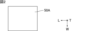
- FIG. 2 is a schematic plan view showing the film member in FIG. 1 in a state before being stretched in the length direction.
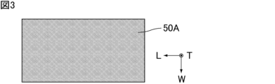
- FIG. 3 is a schematic plan view showing the state of the film member in FIG. 1 after being stretched in the length direction.
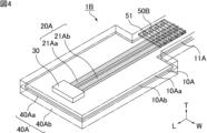
- FIG. 4 is a schematic perspective view showing an example of a stretchable wiring board according to Embodiment 2 of the present invention.
- FIG. 5 is a schematic plan view showing the film member in FIG. 4 in a state before being stretched in the length direction.
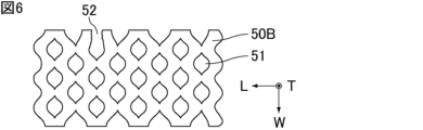
- FIG. 6 is a schematic plan view showing the state of the film member in FIG. 4 after being stretched in the length direction.
- the stretchable wiring board of the present invention will be explained. Note that the present invention is not limited to the following configuration, and may be modified as appropriate without departing from the gist of the present invention. Furthermore, the present invention also includes a combination of a plurality of individual preferred configurations described below.
- the stretchable wiring board of the present invention includes a stretchable base material having a first main surface and a second main surface facing each other in the thickness direction, and provided on at least the first main surface side of the stretchable base material, and a wiring member comprising at least one stretchable wiring extending in a plane direction including a length direction perpendicular to the thickness direction and a width direction perpendicular to the thickness direction and the length direction; a protective member that covers at least one of the first main surface and the second main surface; a film member provided on at least one of the stretchable base material side and the opposite side to the stretchable base material with respect to the protective member; , wherein the film member irreversibly changes in appearance when stretched in the length direction.
- the film member changes from a transparent state to an opaque state when stretched in the length direction.
- FIG. 1 is a schematic perspective view showing an example of a stretchable wiring board according to Embodiment 1 of the present invention.
- the stretchable wiring board 1A shown in FIG. 1 includes a stretchable base material 10A, a wiring member 20A, a protection member 40A, and a film member 50A.
- the length direction, thickness direction, and width direction are defined by L, T, and W, respectively, as shown in FIG. 1 and the like.
- the length direction L, the thickness direction T, and the width direction W are orthogonal to each other.
- a direction perpendicular to the thickness direction T and including the length direction L and the width direction W is defined as a surface direction.
- the stretchable base material 10A has a first main surface 10Aa and a second main surface 10Ab that face each other in the thickness direction T.
- the stretchable base material 10A has a narrow portion 11A having a minimum cross-sectional area when viewed in a cross section perpendicular to the length direction L.
- the dimension of the stretchable base material 10A in the thickness direction T is constant regardless of the position along the length direction L. That is, in the example shown in FIG. 1, the narrow portion 11A corresponds to the portion of the stretchable base material 10A that has the smallest dimension in the width direction W. In addition, when the dimension in the width direction W of the stretchable base material 10A is constant regardless of the position along the length direction L, the narrow portion 11A is, for example, a dimension in the thickness direction T of the stretchable base material 10A. This corresponds to the part with the smallest dimensions.
- the stretchable base material 10A preferably contains at least one resin selected from the group consisting of styrene resins, olefin resins, and silicone resins.
- styrene resin examples include styrene-butadiene-styrene copolymer resin (SBS).
- the dimension of the stretchable base material 10A in the thickness direction T is preferably 100 ⁇ m or less, more preferably 50 ⁇ m or less. Since the dimension in the thickness direction T of the stretchable base material 10A is within the above range, when the stretchable wiring board 1A is used while attached to a human body, the stretchable wiring board 1A can follow the movement of the human body. It becomes easier.
- the dimension of the stretchable base material 10A in the thickness direction T is preferably 10 ⁇ m or more.
- the elongation at break in the length direction L of the stretchable base material 10A is preferably 50% or more. Since the elongation at break in the length direction L of the stretchable base material 10A is within the above range, when the stretchable wiring board 1A is used in a state where it is attached to a human body, the stretchable wiring board 1A will be able to withstand the movements of the human body. becomes easier to follow.
- the Young's modulus of the stretchable base material 10A is preferably 100 MPa or less, more preferably 30 MPa or less. Since the Young's modulus of the stretchable base material 10A is within the above range, when the stretchable wiring board 1A is used while being attached to the human body, the stretchable wiring board 1A is less likely to inhibit the expansion and contraction of the surface of the human body. Therefore, discomfort caused by the stretchable wiring board 1A is less likely to occur.
- the Young's modulus of the stretchable base material 10A is preferably 3 MPa or more.
- the shape of the stretchable base material 10A when viewed from the thickness direction T is such that the dimension in the width direction W is larger at one end than at the other portion.
- the shape of the stretchable base material 10A when viewed from the thickness direction T may be such that the dimension in the width direction W is constant regardless of the position along the length direction L.
- the shape of the stretchable base material 10A when viewed from the thickness direction T is such that one end is loop-shaped, for example, a linear portion and a loop-shaped portion are connected in the length direction L. It may also have a different shape. In this case, the stretchable base material 10A may have a narrow portion at a position where the linear portion and the loop portion are connected.
- the wiring member 20A is provided at least on the first main surface 10Aa side of the stretchable base material 10A.
- the wiring member 20A is provided on the first main surface 10Aa side of the stretchable base material 10A.
- wiring member 20A may be provided on the second main surface 10Ab side of the elastic base material 10A in addition to the first main surface 10Aa side of the elastic base material 10A.
- the wiring member 20A is provided on the first main surface 10Aa of the stretchable base material 10A. That is, in the example shown in FIG. 1, the stretchable base material 10A and the wiring member 20A are in contact with each other.
- the wiring member 20A is composed of at least one stretchable wiring extending in the plane direction including the length direction L and the width direction W.
- the wiring member 20A is composed of two stretchable wires 21Aa and 21Ab extending in the plane direction.
- the wiring member 20A may be composed of only one stretchable wire, or may be composed of three or more stretchable wires.
- the dimension in the thickness direction T of the stretchable wiring, and the dimension in the thickness direction T of the stretchable wiring 21Aa and the stretchable wiring 21Ab in the example shown in FIG. 1, is preferably 100 ⁇ m or less, more preferably 50 ⁇ m or less. Since the dimension of the stretchable wiring in the thickness direction T is within the above range, the stretchable wiring board 1A can easily follow the movement of the human body when the stretchable wiring board 1A is used while being attached to the human body. .
- the dimension in the thickness direction T of the stretchable wiring, the dimension in the thickness direction T of the stretchable wiring 21Aa and the stretchable wiring 21Ab in the example shown in FIG. 1, is preferably 1 ⁇ m or more, more preferably 10 ⁇ m or more.
- the stretchable wiring, the stretchable wire 21Aa and the stretchable wire 21Ab in the example shown in FIG. 1, contain, for example, conductive particles and resin.
- Examples of the constituent material of the conductive particles included in the stretchable wiring include metals such as silver, copper, and nickel. Among them, silver is preferable from the viewpoint of realizing low resistance of the stretchable wiring.
- the average particle size of the conductive particles contained in the stretchable wiring is preferably 0.01 ⁇ m or more and 10 ⁇ m or less.
- the average particle size of the conductive particles included in the stretchable wiring is determined as follows. First, the stretchable wiring board is polished or the like so that a cross section in which the target stretchable wiring is exposed appears. Next, an image of the cross section is taken using a scanning electron microscope (SEM) or the like. Then, by performing an image analysis of the photographed cross-sectional image, the equivalent circular diameter of the conductive particles included in the stretchable wiring is measured, and the obtained equivalent circular diameter is taken as the particle size of the conductive particles. Thereafter, the number-based cumulative particle size distribution is calculated from the particle size of the obtained conductive particles, and the particle size (median diameter D 50 ) at which the cumulative probability is 50% in the number-based cumulative particle size distribution is determined as the conductive particle size. Defined as the average particle size of the particles.
- the shape of the conductive particles included in the stretchable wiring is preferably spherical.
- the shape of the conductive particles included in the stretchable wiring may be other than spherical, such as a flat shape, an irregular shape having protrusions, etc., from the viewpoint of reducing the change in resistance of the stretchable wire due to expansion and contraction.
- the conductive particles contained in each stretchable wiring are preferably the same, at least in terms of the type of constituent material, but are not different from each other. It may be different, or it may be different in some parts.
- the resin contained in the stretchable wiring is preferably at least one elastomer resin selected from the group consisting of epoxy resins, urethane resins, acrylic resins, and silicone resins. In this case, the stretchability of the stretchable wiring is easily ensured. Note that the resin contained in the stretchable wiring may be any resin other than those described above as long as it can impart a stretchable function.
- the resins contained in each stretchable wire are preferably the same, at least in terms of type, but may be different from each other, or It may be different in some parts.
- the stretchable wiring, the stretchable wire 21Aa and the stretchable wire 21Ab in the example shown in FIG. 1, are formed, for example, as follows.
- a conductive paste containing conductive particles and a resin is applied to at least the first main surface 10Aa of the stretchable base material 10A.
- the method for applying the conductive paste include a screen printing method, an inkjet method, and a dispensing method.
- stretchable wiring is formed.
- each of the stretchable wiring 21Aa and the stretchable wiring 21Ab is electrically connected to the electronic component 30. That is, the stretchable wiring 21Aa and the stretchable wiring 21Ab constitute an electrical path to the outside, and in the example shown in FIG. 1, an electrical path to the external electronic component 30.
- the electronic component 30 is mounted on each of the stretchable wiring 21Aa and the stretchable wiring 21Ab via a joining member such as solder.
- Examples of the electronic components 30 include diodes, integrated circuits (ICs), capacitors, resistors, inductors, amplifiers (operational amplifiers, transistors, etc.), and the like.
- the protective member 40A covers at least one of the first main surface 10Aa and the second main surface 10Ab of the stretchable base material 10A.
- the protective member 40A covers both the first main surface 10Aa and the second main surface 10Ab of the elastic base material 10A.
- the protective member 40A may cover only the first main surface 10Aa of the stretchable base material 10A, or may cover only the second main surface 10Ab of the stretchable base material 10A.
- the protection member 40A is composed of a first protection part 40Aa and a second protection part 40Ab.
- the first protection part 40Aa covers the first main surface 10Aa of the stretchable base material 10A
- the second protection part 40Ab covers the second main surface 10Ab of the stretchable base material 10A.
- the protection member 40A more specifically, the first protection part 40Aa covers the wiring member 20A and the electronic component 30 while covering the first main surface 10Aa of the elastic base material 10A. .
- the protective member 40A By covering the wiring member 20A and the electronic component 30 with the protective member 40A, the following effects can be obtained. - The wiring member 20A and the electronic component 30 are protected from the outside. - The moisture resistance of the wiring member 20A and the electronic component 30 is improved. - Chemical substances used in the wiring member 20A and the electronic component 30 are prevented from coming into contact with the human body. - Electrical leakage from the wiring member 20A and the electronic component 30 to the human body is prevented.
- the constituent materials of the protective member 40A, and the constituent materials of the first protective part 40Aa and the second protective part 40Ab in the example shown in FIG. 1, include, for example, polyvinyl chloride, polyethylene, polystyrene, polycarbonate, polyvinylidene fluoride, polyimide, and liquid crystal.
- examples include elastomer resins such as polymers, polytetrafluoroethylene, phenol resins, epoxy resins, urethane resins, acrylic resins, silicone resins, and styrene-butadiene resins.
- the protective member 40A is formed, for example, by pressing a film containing the above-mentioned material onto at least one of the first main surface 10Aa and the second main surface 10Ab of the elastic base material 10A.
- the protective member 40A may be configured, for example, by applying a slurry containing the above-mentioned material to at least one of the first main surface 10Aa and the second main surface 10Ab of the elastic base material 10A, and then heat-treating the applied slurry.
- it is formed by UV treatment.
- the slurry coating method include a screen printing method, an inkjet method, and a dispensing method.
- the film member 50A is provided on at least one of the stretchable base material 10A side and the opposite side to the stretchable base material 10A with respect to the protection member 40A.
- the film member 50A is provided on the opposite side of the protective member 40A to the stretchable base material 10A.
- the film member 50A is provided on the opposite side of the stretchable base material 10A of the first protection section 40Aa.
- the film member 50A is provided on the side opposite to the stretchable base material 10A of the first protective portion 40Aa, so that the portion where the film member 50A is provided, that is, the first protective portion 40Aa and The areas where the film members 50A overlap are mechanically reinforced.
- film member 50A may be provided on the opposite side of the elastic base material 10A of the second protection portion 40Ab.
- the film member 50A may be provided on both the first protection part 40Aa on the opposite side to the stretchable base material 10A and the second protection part 40Ab on the opposite side to the stretchable base material 10A.
- the film member 50A is provided on the main surface of the first protective portion 40Aa on the opposite side to the stretchable base material 10A. That is, in the example shown in FIG. 1, the protection member 40A and the film member 50A are in contact with each other.
- the film member 50A may be provided on the stretchable base material 10A side of the protective member 40A. More specifically, the film member 50A may be provided only on the elastic base material 10A side of the first protection part 40Aa, or may be provided only on the elastic base material 10A side of the second protection part 40Ab. Alternatively, it may be provided both on the stretchable base material 10A side of the first protection section 40Aa and on the stretchable base material 10A side of the second protection section 40Ab.
- film member 50A may be provided on both the stretchable base material 10A side of the protective member 40A and the opposite side of the stretchable base material 10A of the protective member 40A.
- each of the stretchable wiring 21Aa and the stretchable wiring 21Ab is electrically connected to the electronic component 30.
- the stretchable wiring 21Aa and the stretchable wiring 21Ab function as drive wiring through which a large current flows to drive the light emitting diode.
- the stretchable wiring board 1A is stretched excessively in the length direction L, the resistance of the stretchable wires 21Aa and 21Ab becomes too high as the stretchable wires 21Aa and 21Ab stretch.
- the stretchable wiring board 1A when the film member 50A is stretched in the length direction L, the appearance changes irreversibly.
- the stretchable wiring 21Aa and the stretchable wiring 21Ab are stretched in the length direction L.
- the stretchability of the stretchable wiring board 1A is such that the stretchable wiring board 1A is stretched excessively in the length direction L. An excessively stretched state of the wiring board 1A can be detected.
- the stretching rate of the film member 50A and the timing at which the appearance of the film member 50A changes are known in advance, and by providing the film member 50A as described above, the stretchable wiring board 1A The timing at which the appearance of the film member 50A changes when stretched in the length direction L, that is, the timing at which an excessively stretched state of the stretchable wiring board 1A is detected can be adjusted.
- the stretchable wiring board 1A when the stretchable wiring board 1A is stretched in the length direction L, the appearance of the film member 50A changes irreversibly, so that there is no trace that the stretchable wiring board 1A has been stretched excessively in the length direction L. You can leave it behind. That is, from the stretchable wiring board 1A in which the appearance of the film member 50A has changed, it is possible to confirm the past history of the stretchable wiring board 1A being excessively stretched in the length direction L.
- the stretchable wiring board 1A when the stretchable wiring board 1A is used, at the time when the appearance of the film member 50A changes, that is, before the stretchable wiring 21Aa and the stretchable wiring 21Ab are excessively stretched in the length direction L. , the user can be prompted to stop using the stretchable wiring board 1A. In other words, when the stretchable wiring board 1A is used, the stretchable wiring 21Aa and the stretchable wiring 21Ab are stretched excessively in the length direction L, so that the stretchable wire 21Aa and the stretchable wire 21Ab are stretched excessively. The user can be prompted to stop using the stretchable wiring board 1A before it generates heat.
- the stretchable wiring board 1A it is possible to realize a stretchable wiring board that can safely detect an excessively stretched state.
- the term "the appearance of the film member irreversibly changes when it is stretched in the length direction” means that the appearance changes when the film member is stretched in the length direction, and This means that even if it is stretched in the horizontal direction and then shrunk to its original state, it will not return to its original appearance.
- the appearance of the film member includes the color, shape, etc. of the film member.
- FIG. 2 is a schematic plan view showing the film member in FIG. 1 in a state before being stretched in the length direction.
- FIG. 3 is a schematic plan view showing the state of the film member in FIG. 1 after being stretched in the length direction.
- the film member 50A changes from an opaque state to a transparent state. do not.
- the film member 50A may be made of a resin that changes from an amorphous state to a crystalline state when the film member 50A is stretched in the length direction L.
- the molecular structure of the resin constituting the film member 50A is in an amorphous state (also called amorphous plastic) before the film member 50A is stretched in the length direction L, so the film member 50A is Before being stretched in the length direction L, it is in a transparent state that allows light to pass through.
- the resin constituting the film member 50A changes its molecular structure and becomes a crystalline state (also called crystalline plastic) when the film member 50A is stretched in the length direction L. , after being stretched in the length direction L, it becomes an opaque state that diffusely reflects light.
- the resin when the resin changes from an amorphous state to a crystalline state, it means that string-like polymers change from an irregularly entangled state to a regularly arranged state in the solidified state of the resin, preferably. means that the degree of orientation of the resin changes from a state of 1% or less to a state of 20% or more.
- the degree of orientation of the resin is calculated, for example, from the crystal peak of the resin measured by an X-ray diffraction method or the like.
- the constituent material of the film member 50A is preferably polyethylene.
- the film member 50A may include microcapsules containing a dye that can be destroyed when the film member 50A is stretched in the length direction L. In this case, when the film member 50A is stretched in the length direction L, the microcapsules contained in the film member 50A are destroyed and the dye oozes out, causing the color of the film member 50A to change as a whole and become opaque. state.
- the film member 50A when stretched in the length direction L, it changes from a transparent state to an opaque state, thereby irreversibly changing the color as an example of the appearance.
- the narrow portion 11A corresponds to the portion of the stretchable base material 10A that has the smallest cross-sectional area when viewed in a cross section perpendicular to the length direction L. Therefore, when the stretchable wiring board 1A is stretched in the length direction L, stress tends to concentrate on the narrow part 11A of the stretchable base material 10A, and as a result, the narrow part 11A stretches more than other parts. It becomes easier.
- the film member 50A is provided at a position overlapping the narrow portion 11A when viewed from the thickness direction T. That is, in the stretchable wiring board 1A, the film member 50A whose appearance changes irreversibly when stretched in the length direction L is different from the film member 50A whose appearance changes irreversibly when stretched in the length direction L. It is provided in the narrow portion 11A that will extend the most. Therefore, according to the stretchable wiring board 1A in which the film member 50A is provided in the narrow part 11A, the film member 50A is not stretched in the length direction L compared to the stretchable wiring board in which the film member 50A is not provided in the narrow part 11A. When this occurs, the appearance of the film member 50A tends to change more quickly, so that an excessively stretched state can be detected earlier.
- the film member 50A is provided only at a position overlapping the narrow portion 11A when viewed from the thickness direction T.
- the film member 50A may be provided at a position where it does not overlap the narrow portion 11A when viewed from the thickness direction T.
- the tensile strength in the length direction L of the film member 50A is preferably lower than the tensile strength in the length direction L of the wiring member 20A.
- the stretchable wiring board 1A is stretched in the length direction L
- the film is removed before the wiring member 20A is disconnected due to the wiring member 20A being stretched excessively in the length direction L.
- the member 50A will break.
- the film member 50A is stretched in the length direction L, not only the color as an example of the appearance but also the shape irreversibly changes. detection becomes easier.
- the protective member 40A does not break before the wiring member 20A. That is, when the stretchable wiring board 1A is stretched in the length direction L, at the time when the wiring member 20A is disconnected due to the wiring member 20A being stretched excessively in the length direction L, the protection member 40A is Will not break.
- the stretchable wiring board 1A when the stretchable wiring board 1A is used, when the film member 50A detects that the wiring member 20A has been stretched excessively in the length direction L, the protective member 40A breaks. Therefore, before problems such as chemical substances used in the wiring member 20A and the electronic component 30 coming into contact with the human body or electrical leakage from the wiring member 20A and the electronic component 30 to the human body occur, the elasticity The user can be prompted to stop using the wiring board 1A. As a result, safety when using the stretchable wiring board 1A having the protection member 40A is improved.
- the elongation rate at break in the length direction L of the protective member 40A, and the elongation rate at break in the length direction L of each of the first protection part 40Aa and the second protection part 40Ab in the example shown in FIG. 1, is preferably 200% or more. be.
- the elongation rate at break in the length direction L of the protective member 40A, and the elongation rate at break in the length direction L of each of the first protection part 40Aa and the second protection part 40Ab in the example shown in FIG. 1, is preferably 800% or less. be.
- the stretchable wiring board 1A may further include an electrode connected to at least one of the stretchable wiring 21Aa and the stretchable wiring 21Ab.
- the stretchable wiring board 1A can function as a sensor by being attached to the human body via such electrodes.
- the sensor Excessive elongation can be detected before an abnormality occurs.
- the electrode is preferably a gel electrode.
- the gel electrode is made of a conductive gel material containing, for example, water, alcohol, a humectant, an electrolyte, and the like. Examples of such gel materials include hydrogels and the like.
- the film member is provided with a cut that can be broken when stretched in the length direction.
- the stretchable wiring board of Embodiment 2 of the present invention is the same as the stretchable wiring board of Embodiment 1 of the present invention except for this point.
- FIG. 4 is a schematic perspective view showing an example of a stretchable wiring board according to Embodiment 2 of the present invention.
- the stretchable wiring board 1B shown in FIG. 4 includes a stretchable base material 10A, a wiring member 20A, a protection member 40A, and a film member 50B. That is, the stretchable wiring board 1B differs from the stretchable wiring board 1A in that it has a film member 50B instead of the film member 50A.
- FIG. 5 is a schematic plan view showing the film member in FIG. 4 in a state before being stretched in the length direction.
- FIG. 6 is a schematic plan view showing the state of the film member in FIG. 4 after being stretched in the length direction.
- the film member 50B is provided with a notch 51 that can be broken when stretched in the length direction L.
- the cut 51 is not broken.
- the cut 51 is broken at a break point 52.
- the shape of the film member 50B changes when it is stretched in the length direction L.
- the cut 51 remains broken at the break point 52. Therefore, the shape will not return to its original shape.
- the shape which is an example of the appearance, irreversibly changes.
- the stretchable wiring board 1B by utilizing the fact that the appearance of the film member 50B irreversibly changes when stretched in the length direction L, the stretchable wiring board 1B can avoid excessive A stretchable wiring board that can safely detect the stretched state can be realized.
- the cut 51 is preferably provided along the width direction W.
- the relationship between the dimension D2 of the notch 51 in the width direction W and the elongation rate at break in the length direction L of the film member 50B until the notch 51 breaks is grasped in advance, and the above-mentioned By providing the cut 51 along the width direction W as shown in FIG. , the timing at which the excessively stretched state of the stretchable wiring board 1B is detected can be adjusted.
- the notches 51 are also determined by the distance D1 between the notches 51 in the length direction L and the distance D3 between the notches 51 in the width direction W.
- the elongation rate at break in the length direction L of the film member 50B until it breaks can be adjusted. For example, if the distance D1 between the notches 51 in the length direction L is shortened and the dimension D2 of the notches 51 in the width direction W is lengthened, the elongation at break in the length direction L of the film member 50B until the notches 51 break. can be made higher.
- the cut 51 may be provided along a surface direction other than the width direction W (for example, the length direction L).
- a plurality of cuts 51 are provided.
- the plurality of cuts 51 are arranged in the same straight line along the width direction W.
- the plurality of cuts 51 are provided so that rows of the cuts 51 lined up in the same straight line along the width direction W are spaced apart from each other in the length direction L.
- the relationship between the number, arrangement, etc. of the notches 51 and the elongation rate at break in the length direction L of the film member 50B until the notches 51 break is understood in advance.
- the timing at which the appearance of the film member 50B changes (the notches 51 break) when the stretchable wiring board 1B is stretched in the length direction L that is, the timing of expansion and contraction.
- the timing at which the excessively stretched state of the flexible wiring board 1B is detected can be adjusted.
- the film member 50B is made of non-stretchable resin. In this case, when the film member 50B is stretched in the length direction L, the cuts 51 are more likely to break earlier, so the appearance of the film member 50B is more likely to change earlier.
- the resin is non-stretchable when the resin is molded into a resin film with a length of 18 mm, a width of 5 mm, and a thickness of 38 ⁇ m. It means 1 GPa or more.
- the constituent material of the film member 50B is preferably at least one of polyethylene terephthalate and polyimide. That is, the constituent material of the film member 50B is preferably polyethylene terephthalate, more preferably polyimide, and more preferably a mixture of polyethylene terephthalate and polyimide.
- the stretchable wiring board when used, the stretchable wiring board is stretched in the length direction. It may be stretched in a plane direction other than the direction (for example, the width direction).
- a stretchable base material having a first main surface and a second main surface facing each other in the thickness direction; At least one of the stretchable substrates is provided on at least the first main surface side and extends in a plane direction including a length direction perpendicular to the thickness direction and a width direction perpendicular to the thickness direction and the length direction.
- a wiring member consisting of one stretchable wiring, a protective member that covers at least one of the first main surface and the second main surface of the stretchable base material;
- a film member provided on at least one of the stretchable base material side and the opposite side to the stretchable base material with respect to the protective member, A stretchable wiring board, wherein the film member irreversibly changes in appearance when stretched in the length direction.
- ⁇ 5> The stretchable wiring board according to any one of ⁇ 1> to ⁇ 4>, wherein the film member is provided with a cut that can be broken when stretched in the length direction.
- the stretchable base material has a narrow portion having a minimum cross-sectional area when viewed in a cross section perpendicular to the length direction,
- the stretchable wiring board according to any one of ⁇ 1> to ⁇ 8>, wherein the film member is provided at a position overlapping the narrow portion when viewed from the thickness direction.
Landscapes
- Engineering & Computer Science (AREA)
- Microelectronics & Electronic Packaging (AREA)
- Structure Of Printed Boards (AREA)
Priority Applications (2)
| Application Number | Priority Date | Filing Date | Title |
|---|---|---|---|
| JP2024528805A JP7632755B2 (ja) | 2022-06-20 | 2023-06-09 | 伸縮性配線基板 |
| US18/973,337 US20250106986A1 (en) | 2022-06-20 | 2024-12-09 | Stretchable wiring board |
Applications Claiming Priority (2)
| Application Number | Priority Date | Filing Date | Title |
|---|---|---|---|
| JP2022-098928 | 2022-06-20 | ||
| JP2022098928 | 2022-06-20 |
Related Child Applications (1)
| Application Number | Title | Priority Date | Filing Date |
|---|---|---|---|
| US18/973,337 Continuation US20250106986A1 (en) | 2022-06-20 | 2024-12-09 | Stretchable wiring board |
Publications (1)
| Publication Number | Publication Date |
|---|---|
| WO2023248831A1 true WO2023248831A1 (ja) | 2023-12-28 |
Family
ID=89379680
Family Applications (1)
| Application Number | Title | Priority Date | Filing Date |
|---|---|---|---|
| PCT/JP2023/021507 Ceased WO2023248831A1 (ja) | 2022-06-20 | 2023-06-09 | 伸縮性配線基板 |
Country Status (3)
| Country | Link |
|---|---|
| US (1) | US20250106986A1 (https=) |
| JP (1) | JP7632755B2 (https=) |
| WO (1) | WO2023248831A1 (https=) |
Citations (5)
| Publication number | Priority date | Publication date | Assignee | Title |
|---|---|---|---|---|
| JP2001106984A (ja) * | 1999-10-01 | 2001-04-17 | Nitto Denko Corp | 局所変位検知用粘着フィルムまたはシート |
| JP2013213710A (ja) * | 2012-04-02 | 2013-10-17 | Kawasaki Heavy Ind Ltd | コンクリート微小ひび割れセンサ |
| JP2017177342A (ja) * | 2016-03-28 | 2017-10-05 | 大阪ガスケミカル株式会社 | 多層光学フィルム及びその製造方法 |
| WO2019045108A1 (ja) * | 2017-09-04 | 2019-03-07 | パナソニックIpマネジメント株式会社 | 伸縮性回路基板、及び、それを用いたパッチデバイス |
| JP2020155563A (ja) * | 2019-03-20 | 2020-09-24 | 大日本印刷株式会社 | 配線基板 |
-
2023
- 2023-06-09 JP JP2024528805A patent/JP7632755B2/ja active Active
- 2023-06-09 WO PCT/JP2023/021507 patent/WO2023248831A1/ja not_active Ceased
-
2024
- 2024-12-09 US US18/973,337 patent/US20250106986A1/en active Pending
Patent Citations (5)
| Publication number | Priority date | Publication date | Assignee | Title |
|---|---|---|---|---|
| JP2001106984A (ja) * | 1999-10-01 | 2001-04-17 | Nitto Denko Corp | 局所変位検知用粘着フィルムまたはシート |
| JP2013213710A (ja) * | 2012-04-02 | 2013-10-17 | Kawasaki Heavy Ind Ltd | コンクリート微小ひび割れセンサ |
| JP2017177342A (ja) * | 2016-03-28 | 2017-10-05 | 大阪ガスケミカル株式会社 | 多層光学フィルム及びその製造方法 |
| WO2019045108A1 (ja) * | 2017-09-04 | 2019-03-07 | パナソニックIpマネジメント株式会社 | 伸縮性回路基板、及び、それを用いたパッチデバイス |
| JP2020155563A (ja) * | 2019-03-20 | 2020-09-24 | 大日本印刷株式会社 | 配線基板 |
Also Published As
| Publication number | Publication date |
|---|---|
| JP7632755B2 (ja) | 2025-02-19 |
| JPWO2023248831A1 (https=) | 2023-12-28 |
| US20250106986A1 (en) | 2025-03-27 |
Similar Documents
| Publication | Publication Date | Title |
|---|---|---|
| KR102741702B1 (ko) | 스트레처블 터치 스크린, 이의 제조 방법 및 이를 이용한 표시 장치 | |
| TWI275863B (en) | Flexible substrate being able to prevent plastic deformation and flexible image display | |
| ES2587906T3 (es) | Dispositivo de visualización | |
| CN107004774B (zh) | 具有耐腐蚀印刷电路膜的柔性显示装置 | |
| TWI471790B (zh) | 電容式觸控感應器及其製造方法及電容式觸控面板 | |
| CN110867522B (zh) | 显示装置 | |
| KR970067060A (ko) | 집적 전기 광학 패키지 | |
| CN109375399A (zh) | 显示装置 | |
| TW200813961A (en) | Organic light emitting diode display and method of manufacturing the same | |
| KR20190019557A (ko) | 터치 센서 및 이를 포함하는 화상 표시 장치 | |
| CN104731429A (zh) | 触摸面板 | |
| JP7111232B2 (ja) | 伸縮性実装基板 | |
| JP4749764B2 (ja) | 湾曲検出装置及び可撓性装置 | |
| WO2023248831A1 (ja) | 伸縮性配線基板 | |
| TWI736098B (zh) | 耐彎折結構及顯示面板 | |
| KR20180005312A (ko) | 표시 장치 | |
| US10991852B2 (en) | Transparent light-emitting display film, method of manufacturing the same, and transparent light-emitting signage using the same | |
| JP7632754B2 (ja) | 伸縮性配線基板 | |
| TWI622917B (zh) | 觸控裝置 | |
| US20080001940A1 (en) | Display device and manufacturing method thereof | |
| CN118401078A (zh) | 显示面板和显示装置 | |
| KR20200066919A (ko) | 유기발광 표시장치 | |
| JP6892561B2 (ja) | 交差するワイヤを含む照明装置 | |
| JP7523921B2 (ja) | 電子機器 | |
| CN113593418A (zh) | 显示面板及其制作方法、移动终端 |
Legal Events
| Date | Code | Title | Description |
|---|---|---|---|
| 121 | Ep: the epo has been informed by wipo that ep was designated in this application |
Ref document number: 23827017 Country of ref document: EP Kind code of ref document: A1 |
|
| WWE | Wipo information: entry into national phase |
Ref document number: 2024528805 Country of ref document: JP |
|
| NENP | Non-entry into the national phase |
Ref country code: DE |
|
| 122 | Ep: pct application non-entry in european phase |
Ref document number: 23827017 Country of ref document: EP Kind code of ref document: A1 |