WO2023248268A1 - 固定子、回転電機、圧縮機及び冷凍サイクル装置 - Google Patents
固定子、回転電機、圧縮機及び冷凍サイクル装置 Download PDFInfo
- Publication number
- WO2023248268A1 WO2023248268A1 PCT/JP2022/024446 JP2022024446W WO2023248268A1 WO 2023248268 A1 WO2023248268 A1 WO 2023248268A1 JP 2022024446 W JP2022024446 W JP 2022024446W WO 2023248268 A1 WO2023248268 A1 WO 2023248268A1
- Authority
- WO
- WIPO (PCT)
- Prior art keywords
- coil
- stator
- phase
- stator winding
- copper wires
- Prior art date
- Legal status (The legal status is an assumption and is not a legal conclusion. Google has not performed a legal analysis and makes no representation as to the accuracy of the status listed.)
- Ceased
Links
Images





Classifications
-
- H—ELECTRICITY
- H02—GENERATION; CONVERSION OR DISTRIBUTION OF ELECTRIC POWER
- H02K—DYNAMO-ELECTRIC MACHINES
- H02K3/00—Details of windings
- H02K3/02—Windings characterised by the conductor material
-
- H—ELECTRICITY
- H02—GENERATION; CONVERSION OR DISTRIBUTION OF ELECTRIC POWER
- H02K—DYNAMO-ELECTRIC MACHINES
- H02K3/00—Details of windings
- H02K3/04—Windings characterised by the conductor shape, form or construction, e.g. with bar conductors
- H02K3/12—Windings characterised by the conductor shape, form or construction, e.g. with bar conductors arranged in slots
Definitions
- the present disclosure relates to a stator including a stator winding partially using aluminum wire, a rotating electrical machine including the stator, a compressor including the rotating electrical machine, and a refrigeration cycle device including the compressor. Regarding.
- the aluminum wire since the aluminum wire has a higher electrical resistivity than the copper wire, it generates a larger amount of heat when energized. Therefore, when using copper wire and aluminum wire for the stator winding, it is required to enhance the heat dissipation effect. Therefore, in a conventional stator using copper wire and aluminum wire for the stator winding, the stator winding is constructed such that the aluminum wire is densely packed in one place within the slot portion.
- the present disclosure has been made in order to solve the above-mentioned problems, and is a stator that uses copper wire and aluminum wire for the stator winding, and is a fixing device that can suppress a decrease in efficiency of a rotating electric machine more than before.
- the primary purpose is to provide children.
- a second object of the present disclosure is to provide a rotating electrical machine including such a stator, a compressor including the rotating electrical machine, and a refrigeration cycle device including the compressor.
- the stator according to the present disclosure includes a cylindrical core back portion and a plurality of teeth portions protruding from the core back portion toward an inner peripheral side of the core back portion, and the teeth adjacent to the core back portion
- the stator windings of the same phase are inserted into the same slot, each of the coils having a copper wire and an aluminum wire;
- the two coils are inserted into the same slot, one of the coils inserted into the same slot is the first coil, and the other of the coils inserted into the same slot is the first coil.
- the first coil is disposed closer to the outer periphery of the stator core than the second coil in the slot portion, and the number of copper wires of the first coil is equal to the number of copper wires of the first coil.
- the first ratio When the value obtained by dividing the number of the aluminum wires of the coil is the first ratio, and the value obtained by dividing the number of the aluminum wires of the second coil by the number of the copper wires of the second coil is the second ratio, The first ratio and the second ratio are the same.
- a rotating electric machine includes a stator according to the present disclosure, and a rotor rotatably provided on the inner peripheral side of the stator.
- a compressor according to the present disclosure includes the rotating electric machine according to the present disclosure and a compression mechanism unit that compresses refrigerant using the driving force of the rotating electric machine.
- a refrigeration cycle device includes a compressor according to the present disclosure, a radiator from which refrigerant compressed by the compressor radiates heat, a pressure reducer for reducing the pressure of the refrigerant flowing out from the radiator, and a pressure reducer for reducing the pressure of the refrigerant flowing out from the radiator. and an evaporator for evaporating the refrigerant flowing out from the container.
- the stator according to the present disclosure can prevent the aluminum wires from becoming denser in the slot portions than before. Therefore, compared to conventional stators that use copper wire and aluminum wire for the stator windings, the stator according to the present disclosure can suppress the local temperature rise in the slot portion, thereby reducing the efficiency of the rotating electric machine. can be suppressed.
- FIG. 1 is a longitudinal sectional view of a scroll compressor according to Embodiment 1.
- FIG. FIG. 3 is a diagram showing a guide frame and a closed container of the scroll compressor according to the first embodiment.
- FIG. 2 is a longitudinal cross-sectional view showing the rotor of the scroll compressor according to the first embodiment.
- FIG. 2 is a cross-sectional view showing the rotor of the scroll compressor according to the first embodiment.
- FIG. 3 is a diagram showing a stator and an airtight container of the scroll compressor according to the first embodiment.
- 1 is a schematic configuration diagram showing a refrigeration cycle device according to Embodiment 1.
- FIG. FIG. 3 is a plan view showing a stator according to the first embodiment.
- FIG. 3 is a plan view showing the stator core and A-phase stator winding of the stator according to the first embodiment.
- FIG. 2 is a side view of the stator according to the first embodiment, with a portion thereof shown as a cross-sectional view.
- FIG. 3 is a cross-sectional view showing the vicinity of the slot portion of the stator according to the first embodiment.
- stator examples of a stator, a rotating electric machine, a compressor, and a refrigeration cycle device according to the present disclosure will be described.
- the stator, rotating electric machine, compressor, and refrigeration cycle device according to the disclosure are not limited to the configurations shown in the following embodiments.
- a vertical scroll compressor is described as an example of a compressor according to the present disclosure.
- the compressor according to the present disclosure may be, for example, a horizontal scroll compressor.
- the compressor according to the present disclosure only needs to include a compression mechanism section that compresses refrigerant using the driving force of the rotating electric machine according to the present disclosure, and may be a compressor equipped with a compression mechanism section other than a scroll type. good.
- drawings shown in each of the embodiments below schematically represent an example of a stator, a rotating electrical machine, a compressor, and a refrigeration cycle device according to the present disclosure. Therefore, the sizes of each component shown in the drawings in each of the embodiments below may differ from those of the stator, rotating electric machine, compressor, and refrigeration cycle device according to the present disclosure that are actually produced. .
- FIG. 1 is a longitudinal sectional view of a scroll compressor according to the first embodiment.
- the configuration and operation of a vertical scroll compressor 100 will be described based on FIG. 1.
- This scroll compressor 100 is, for example, one of the components of a refrigeration cycle device.
- Refrigeration cycle devices are used in various industrial machines such as refrigerators, freezers, air conditioners, refrigeration devices, and water heaters.
- the scroll compressor 100 sucks refrigerant circulating through the refrigeration cycle device, compresses it, and discharges it in a high temperature and high pressure state.
- This scroll compressor 100 includes a compression mechanism section 14 inside a closed container 10.
- the compression mechanism section 14 compresses the refrigerant using the driving force of the rotating electrical machine 5, which will be described later.
- the compression mechanism section 14 is configured by combining a fixed scroll 1 and an oscillating scroll 2 that oscillates with respect to the fixed scroll 1.
- the scroll compressor 100 includes a rotating electrical machine 5 within a closed container 10.
- the rotating electric machine 5 is connected to the swinging scroll 2 through a main shaft 6, and drives the swinging scroll 2.
- the compression mechanism section 14 is arranged on the upper side, and the rotating electric machine 5 is arranged on the lower side.
- the fixed scroll 1 includes a base plate portion 1a and plate-shaped spiral teeth 1b provided on one surface of the base plate portion 1a.
- the plate-shaped spiral tooth 1b is a spiral projection, and in FIG. 1, it is provided on the lower surface of the base plate portion 1a.
- the swinging scroll 2 includes a base plate portion 2a and plate-shaped spiral teeth 2b provided on one surface of the base plate portion 2a.
- the plate-shaped spiral tooth 2b is a spiral protrusion having substantially the same shape as the plate-shaped spiral tooth 1b, and is provided on the upper surface of the base plate portion 2a in FIG. 1.
- the fixed scroll 1 is fixed to the guide frame 4.
- the outer peripheral portion of the fixed scroll 1 is fastened to the guide frame 4 with bolts.
- a suction pipe 13 is provided on the outer periphery of the base plate portion 1a of the fixed scroll 1 for introducing refrigerant gas into the compression chamber 1f from the suction port 1e via the suction check valve 1g.
- a discharge port 1d is formed in the center of the base plate portion 1a of the fixed scroll 1 to discharge compressed high-pressure refrigerant gas.
- the compressed and high-pressure refrigerant gas is then discharged into the upper space 10a within the closed container 10.
- the refrigerant gas discharged into the upper space 10a flows through a refrigerant flow path, which will be described later, and is discharged from the discharge pipe 12.
- the oscillating scroll 2 is configured to perform oscillating motion without rotating relative to the fixed scroll 1 due to the Oldham mechanism 9 for preventing rotational motion.
- a pair of Oldham guide grooves 1c are formed on the outer periphery of the base plate portion 1a of the fixed scroll 1, substantially in a straight line.
- a pair of fixed side keys 9a of the Oldham mechanism 9 are inserted into the Oldham guide groove 1c so as to be able to freely reciprocate and slide.
- a pair of Oldham guide grooves 2c having a phase difference of 90 degrees with the Oldham guide groove 1c of the fixed scroll 1 are formed substantially in a straight line. ing.
- a pair of swing-side keys 9b of the Oldham mechanism 9 are inserted into the Oldham guide groove 2c so as to be able to freely reciprocate and slide.
- the Oldham mechanism 9 configured as described above allows the swinging scroll 2 to perform swinging motion without rotating. Further, a hollow cylindrical boss portion 2d is provided at the center of the surface of the base plate portion 2a of the swinging scroll 2 that is opposite to the surface on which the plate-like spiral teeth 2b are formed. In FIG. 1, the surface of the base plate portion 2a opposite to the surface on which the plate-shaped spiral teeth 2b are formed is the lower surface of the base plate portion 2a. An eccentric shaft portion 6a provided at the upper end of the main shaft 6 is inserted into the boss portion 2d.
- a thrust surface 2f that can slide in pressure contact with the thrust bearing 3a of the compliant frame 3 is formed on the surface of the base plate portion 2a of the swinging scroll 2 opposite to the surface on which the plate-like spiral teeth 2b are formed.
- a bleed hole 2g is formed in the base plate portion 2a of the swinging scroll 2, which communicates the compression chamber 1f with the thrust surface 2f. The bleed hole 2g extracts refrigerant gas during compression and guides it to the thrust surface 2f.
- the compliant frame 3 is housed within the guide frame 4.
- the compliant frame 3 is provided with an upper cylindrical surface portion 3p and a lower cylindrical surface portion 3s on the outer circumference.
- the inner circumference of the guide frame 4 is provided with an upper cylindrical surface portion 4c into which the upper cylindrical surface portion 3p of the compliant frame 3 is fitted, and a lower cylindrical surface portion 4d into which the lower cylindrical surface portion 3s of the compliant frame 3 is fitted.
- the compliant frame 3 is supported in the radial direction within the guide frame 4 by fitting the upper cylindrical surface portion 3p and the upper cylindrical surface portion 4c and fitting the lower cylindrical surface portion 3s and the lower cylindrical surface portion 4d. ing.
- the compliant frame 3 is formed with a communication hole 3e that penetrates from the thrust bearing 3a to the outer peripheral portion of the compliant frame 3.
- the communication hole 3e passes through the compliant frame 3 in the central axis direction of the main shaft 6, for example.
- a thrust bearing opening 3t which is an opening on the thrust bearing 3a side of the communication hole 3e, is arranged to face the bleed hole 2g passing through the base plate portion 2a of the rocking scroll 2.
- a reciprocating sliding surface 3b which is a surface on which the Oldham mechanism annular portion 9c makes reciprocating sliding movement, is formed. Furthermore, a communication hole 3f is formed in the compliant frame 3 so as to communicate with the inner side of the Oldham mechanism annular portion 9c, which communicates the base plate outer peripheral space 2k and the frame upper space 4a. Further, the compliant frame 3 includes an intermediate pressure regulating valve 3g for adjusting the pressure in the boss outer space 2n, an intermediate pressure regulating valve holder 3h, and an intermediate pressure regulating valve holder 3h between the frame upper space 4a and the boss outer space 2n.
- An intermediate pressure regulating valve space 3n is formed in which a spring 3k is housed.
- the intermediate pressure regulating spring 3k is shortened from its natural length and housed in the intermediate pressure regulating valve space 3n.
- the compliant frame 3 and the guide frame 4 are configured separately; however, the present invention is not limited to this, and the compliant frame 3 and the guide frame 4 may be integrated into one frame. good.
- a frame lower space 4b formed by the inner surface of the guide frame 4 and the outer surface of the compliant frame 3 is partitioned above and below by a ring-shaped sealing material 7a and a ring-shaped sealing material 7b.
- a ring-shaped seal groove for accommodating the ring-shaped seal material 7a and a ring-shaped seal groove for accommodating the ring-shaped seal material 7b are formed on the outer peripheral surface of the compliant frame 3. ing.
- at least one of these seal grooves may be formed on the inner peripheral surface of the guide frame 4.
- the frame lower space 4b communicates only with the communication hole 3e of the compliant frame 3, and has a structure in which refrigerant gas that is being compressed and is supplied from the bleed hole 2g is sealed therein.
- the space on the outer circumferential side of the thrust bearing 3a which is vertically surrounded by the base plate part 2a of the swinging scroll 2 and the compliant frame 3, that is, the space 2k in the outer circumferential part of the base plate, becomes a low-pressure space with an intake gas atmosphere. ing.
- FIG. 2 is a diagram showing a guide frame and a closed container of the scroll compressor according to the first embodiment.
- This FIG. 2 is a cross-sectional view of the scroll compressor 100 shown in FIG. 1 taken at the position of the guide frame 4, showing the guide frame 4 and the closed container 10.
- the guide frame 4 is fixed to the closed container 10 by shrink fitting, welding, etc. so that the outer peripheral surface of the guide frame 4 is in contact with the inner peripheral surface of the closed container 10.
- the guide frame 4 is cut out on the outer periphery of the guide frame 4 and the fixed scroll 1, in other words, on the outer periphery of the compression mechanism section 14, a first passage 4f is formed. has been done.
- the refrigerant gas discharged from the discharge port 1d into the upper space 10a of the closed container 10 flows downward into the closed container 10 through the first passage 4f.
- the bottom of the airtight container 10 is an oil reservoir 10b in which refrigerating machine oil 11 is stored.
- the closed container 10 is provided with a discharge pipe 12 for discharging refrigerant gas to the outside of the closed container 10.
- the first passage 4f is provided at a position opposite to the discharge pipe 12.
- the sealed container 10 is formed with a first discharge passage 4g that communicates from the center of the lower end of the guide frame 4 to the side surface.
- the first discharge passage 4g communicates with the discharge pipe 12.
- a discharge cover 16 is provided at the lower end of the guide frame 4 so as to surround the portion where the lower cylindrical surface portion 4d is formed.
- the discharge cover 16 has an opening 16b formed therein.
- the second discharge passage 16a within the discharge cover 16 communicates with the first discharge passage 4g.
- the rotating electrical machine 5 rotates the main shaft 6, and includes a stator 5b and a rotor 5a.
- the stator 5b has a substantially cylindrical shape and is fixed to the closed container 10 by shrink fitting or the like.
- the rotor 5a has a substantially cylindrical shape and is fixed to the main shaft 6 by shrink fitting or the like. Further, the rotor 5a is rotatably provided on the inner peripheral side of the stator 5b. Specifically, the rotor 5a is rotationally driven by starting energization to the stator 5b. Thereby, the main shaft 6 rotates together with the rotor 5a.
- the main shaft 6 also includes an eccentric shaft portion 6a at its upper end portion, which is rotatably inserted into a swing bearing 2e provided at a boss portion 2d of the swing scroll 2. Further, in the main shaft 6, a balance weight 6f is fixed to the lower side of the eccentric shaft portion 6a by shrink fitting or the like.
- the main shaft 6 includes a main shaft portion 6b rotatably inserted into the main bearing 3c and the auxiliary main bearing 3d of the compliant frame 3 below the eccentric shaft portion 6a.
- the main shaft 6 also includes a sub-shaft portion 6c rotatably inserted into a sub-bearing 8a of the sub-frame 8 at its lower end.
- the subframe 8 is formed with an inflow hole 8b through which the refrigerating machine oil 11 flows into the oil reservoir 10b.
- the rotor 5a of the rotating electric machine 5 is fixed to the main shaft 6 between the sub-shaft part 6c and the main shaft part 6b.
- the main shaft 6 is formed with an oil supply passage 6d, which is a hole passing through the main shaft 6 in the axial direction.
- the oil supply port 6e at the lower end of the oil supply path 6d is immersed in refrigerating machine oil 11 stored at the bottom of the airtight container 10. Therefore, the refrigerating machine oil 11 is sucked up from the oil supply port 6e to the oil supply path 6d by the oil supply mechanism or pump mechanism provided at the lower part of the main shaft 6.
- the upper end of the oil supply passage 6d opens into the boss portion 2d of the swinging scroll 2. Therefore, a part of the refrigerating machine oil 11 sucked up into the oil supply path 6d flows out from the opening at the upper end of the oil supply path 6d to the swing bearing 2e, and lubricates the eccentric shaft portion 6a and the swing bearing 2e.
- oil supply holes which branch in the horizontal direction are formed in the oil supply path 6d.
- a part of the refrigerating machine oil 11 sucked up into the oil supply path 6d is supplied to the auxiliary main bearing 3d through the oil supply hole 6g, and lubricates the auxiliary main bearing 3d and the main shaft portion 6b.
- the oil supply hole for the main bearing 3c is not shown in FIG.
- a balance weight 15a is fixed to the upper end surface of the rotor 5a, and a balance weight 15b is fixed to the lower end surface of the rotor 5a.
- the balance weight 15a and the balance weight 15b are fixed at eccentric positions diagonally with respect to the central axis of the rotor 5a.
- the aforementioned balance weight 6f is fixed to the lower part of the eccentric shaft portion 6a of the main shaft 6 in the space outside the boss portion 2d.
- a first cup-shaped member 17 containing a balance weight 15a is fixed to the upper end surface of the rotor 5a
- a second cup-shaped member 18 containing a balance weight 15b is fixed to the lower end surface of the rotor 5a.
- the first cup-shaped member 17 is provided on the upper end surface of the rotor 5a so that the upper opening 17a faces the opening 16b of the discharge cover 16 described above.
- the second cup-shaped member 18 is provided on the lower end surface of the rotor 5a with its opening facing downward.
- the first cup-shaped member 17 and the second cup-shaped member 18 are preferably made of non-magnetic material.
- FIG. 3 is a longitudinal sectional view showing the rotor of the scroll compressor according to the first embodiment.
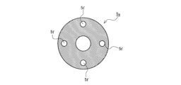
- FIG. 4 is a cross-sectional view showing the rotor of the scroll compressor according to the first embodiment.
- the rotor 5a is formed with a plurality of through passages 5f that penetrate in the direction of the central axis of the rotor 5a. These through passages 5f pass through the bottoms of the first cup-shaped member 17 and the second cup-shaped member 18, avoiding the installation positions of the balance weight 15a and the balance weight 15b.
- each through passage 5f may be formed to pass through the balance weight 15a and the balance weight 15b, or may be formed avoiding the positions of the first cup-shaped member 17 and the second cup-shaped member 18. good. Further, in the first embodiment, the plurality of through passages 5f are formed symmetrically or point symmetrically with respect to the central axis of the rotor 5a.
- FIG. 5 is a diagram showing a stator and an airtight container of the scroll compressor according to the first embodiment.
- FIG. 5 is a cross-sectional view of the scroll compressor 100 shown in FIG. 1 taken at the stator 5b, showing the stator 5b and the closed container 10.
- the stator 5b of the rotating electric machine 5 is fixed to the closed container 10 by shrink fitting, welding, etc. so that the outer peripheral surface of the stator 5b is in contact with the inner peripheral surface of the closed container 10.
- a second passage 5g is formed in the stator 5b by a notch.
- the first passage 4f and the second passage 5g described above constitute a refrigerant flow path 30 that guides the refrigerant gas discharged from the discharge port 1d to the bottom of the closed container 10.
- a glass terminal 10c is installed on the side surface of the closed container 10. This glass terminal 10c and the stator 5b of the rotating electric machine 5 are connected by a lead wire 5h.
- the mixed gas of refrigerant gas and refrigerating machine oil discharged from the discharge port 1d of the fixed scroll 1 into the upper space 10a of the closed container 10 through the compression stroke passes through the refrigerant flow path 30 and passes through the space below the rotating electric machine 5. That is, it is guided to the bottom of the closed container 10.
- the mixed gas is separated in the process of being guided to the bottom of the closed container 10.
- the refrigerant gas separated from the refrigerating machine oil 11 enters the inside through the opening of the second cup-shaped member 18 attached to the lower end surface of the rotor 5a of the rotating electric machine 5, and enters the interior through the through flow path 5f provided in the rotor 5a. flows into.
- the refrigerant gas from which the refrigerating machine oil 11 has been separated rises inside the first cup-shaped member 17 attached to the upper end surface of the rotor 5a and flows into the discharge cover 16. Furthermore, the refrigerant gas from which the refrigerating machine oil 11 has been separated passes through the second discharge passage 16a in the discharge cover 16, the first discharge passage 4g, and further passes through the discharge pipe 12 to be discharged to the outside of the closed container 10.
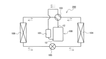
- FIG. 6 is a schematic configuration diagram showing a refrigeration cycle device according to the first embodiment.
- the refrigeration cycle device 200 includes a scroll compressor 100, a radiator from which the refrigerant compressed by the scroll compressor 100 radiates heat, a pressure reducer 105 such as an electric expansion valve that reduces the pressure of the refrigerant flowing out from the radiator, and a pressure reducer 105. and an evaporator for evaporating the refrigerant flowing out from the refrigerant.
- the refrigeration cycle device 200 is used for various purposes such as a refrigerator, a freezer, an air conditioner, a refrigeration device, and a water heater.
- FIG. 6 shows an example in which the refrigeration cycle device 200 is used as an air conditioner.
- the refrigeration cycle device 200 shown in FIG. 6 includes an indoor heat exchanger 106 that functions as a radiator during heating operation, and an outdoor heat exchanger 104 that functions as an evaporator during heating operation.
- the refrigeration cycle device 200 shown in FIG. 6 is also capable of cooling operation.
- the refrigeration cycle device 200 includes a four-way switching valve 103.
- the four-way switching valve 103 switches the heat exchanger connected to the discharge pipe 12 which is the refrigerant discharge port of the scroll compressor 100, and switches the heat exchanger connected to the suction pipe 13 which is the refrigerant suction port of the scroll compressor 100. This is to change the device.
- the indoor heat exchanger 106 functions as an evaporator
- the outdoor heat exchanger 104 functions as a radiator.
- the refrigeration cycle device 200 according to the first embodiment includes a suction muffler 101 between the heat exchanger serving as an evaporator and the scroll compressor 100.
- the indoor heat exchanger 106 is installed in an indoor device.
- the scroll compressor 100, the four-way switching valve 103, the outdoor heat exchanger 104, and the pressure reducer 105 are installed in an outdoor device.
- the refrigeration cycle device 200 uses R407C refrigerant, R410A refrigerant, R32 refrigerant, or the like.
- the four-way switching valve 103 switches to the flow path shown by the solid line in FIG. 6.
- the discharge pipe 12 of the scroll compressor 100 is connected to the indoor heat exchanger 106
- the suction pipe 13 of the scroll compressor 100 is connected to the outdoor heat exchanger 104. That is, the indoor heat exchanger 106 is in a state of functioning as a radiator, and the outdoor heat exchanger 104 is in a state of functioning as an evaporator.
- this state when the high temperature, high pressure refrigerant gas compressed by the scroll compressor 100 is discharged from the scroll compressor 100, this high temperature, high pressure refrigerant gas flows into the indoor heat exchanger 106.
- refrigerant such as carbon dioxide refrigerant
- the radiator may also be referred to as a condenser.
- the high-pressure liquid refrigerant flowing out from the indoor heat exchanger 106 flows into the pressure reducer 105.
- the high-pressure liquid refrigerant that has flowed into the pressure reducer 105 is reduced in pressure by the pressure reducer 105 to become a low-temperature, low-pressure gas-liquid two-phase refrigerant, which flows out from the pressure reducer 105.
- the low-temperature, low-pressure gas-liquid two-phase refrigerant flowing out from the pressure reducer 105 flows into the outdoor heat exchanger 104 .
- the low-temperature, low-pressure gas-liquid two-phase refrigerant that has flowed into the outdoor heat exchanger 104 absorbs heat from the outdoor air, evaporates, and flows out of the outdoor heat exchanger 104 as a low-pressure refrigerant gas.
- the low-pressure refrigerant gas flowing out of the outdoor heat exchanger 104 passes through the suction muffler 101 and is sucked into the scroll compressor 100.
- the low-pressure refrigerant gas sucked into the scroll compressor 100 is compressed by the scroll compressor 100, and becomes high-temperature and high-pressure refrigerant gas.
- This high temperature and high pressure refrigerant gas is discharged from the scroll compressor 100 again. That is, when the refrigeration cycle device 200 performs heating operation, the refrigerant circulates as shown by the solid arrow in FIG. 6 .
- the four-way switching valve 103 switches to the flow path shown by the broken line in FIG. 6.
- the discharge pipe 12 of the scroll compressor 100 is connected to the outdoor heat exchanger 104
- the suction pipe 13 of the scroll compressor 100 is connected to the indoor heat exchanger 106. That is, the outdoor heat exchanger 104 is in a state of functioning as a radiator, and the indoor heat exchanger 106 is in a state of functioning as an evaporator.
- this state when the high temperature, high pressure refrigerant gas compressed by the scroll compressor 100 is discharged from the scroll compressor 100, this high temperature, high pressure refrigerant gas flows into the outdoor heat exchanger 104.
- the high-pressure liquid refrigerant flowing out of the outdoor heat exchanger 104 flows into the pressure reducer 105.
- the high-pressure liquid refrigerant that has flowed into the pressure reducer 105 is reduced in pressure by the pressure reducer 105 to become a low-temperature, low-pressure gas-liquid two-phase refrigerant, which flows out from the pressure reducer 105.
- the low-temperature, low-pressure gas-liquid two-phase refrigerant flowing out of the pressure reducer 105 flows into the indoor heat exchanger 106 .
- the low-temperature, low-pressure gas-liquid two-phase refrigerant that has flowed into the indoor heat exchanger 106 absorbs heat from the indoor air, evaporates, and flows out of the indoor heat exchanger 106 as a low-pressure refrigerant gas. At this time, the indoor air will be cooled.
- the low-pressure refrigerant gas flowing out from the indoor heat exchanger 106 passes through the suction muffler 101 and is sucked into the scroll compressor 100.
- the low-pressure refrigerant gas sucked into the scroll compressor 100 is compressed by the scroll compressor 100, and becomes high-temperature and high-pressure refrigerant gas. This high temperature and high pressure refrigerant gas is discharged from the scroll compressor 100 again. That is, when the refrigeration cycle device 200 performs cooling operation, the refrigerant circulates as shown by the broken arrow in FIG. 6 .
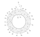
- FIG. 7 is a plan view showing the stator according to the first embodiment. This FIG. 7 can also be said to be a view of the stator 5b observed in the direction of the central axis of the stator 5b.
- the rotating electrical machine 5 according to the first embodiment is a three-phase rotating electrical machine. That is, the stator 5b is a stator of the three-phase rotating electric machine 5.
- the stator 5b includes a stator core 51 and a stator winding wound around the stator core 51.
- the stator core 51 is manufactured by laminating a plurality of electromagnetic steel sheets in the direction of the central axis of the stator core 51.
- the stator core 51 includes a substantially cylindrical core back portion 51a and a plurality of teeth portions 51b protruding from the core back portion 51a toward the inner peripheral side of the core back portion 51a.
- a slot portion 51c is formed between the core back portion 51a and the adjacent teeth portion 51b.
- FIG. 7 illustrates a stator 5b having 6 poles and 18 slot portions 51c.
- the number of poles of the stator 5b is not limited to six, and the number of slot portions 51c of the stator 5b is not limited to eighteen either.
- a stator winding is provided for each phase.
- the stator 5b of the three-phase rotating electric machine 5 includes a stator winding for each phase.
- the stator 5b of the three-phase rotating electric machine 5 includes three stator windings.
- each of the stator windings includes a plurality of coils inserted into the slot portions 51c across a prescribed number of teeth portions 51b.
- each of the stator windings includes s/3 coils.
- each of the stator windings includes six coils. Each of the coils is inserted into the slot portion 51c across the three teeth portions 51b.
- stator winding 52 A-phase stator winding
- stator winding 53 B-phase stator winding
- stator winding 54 stator winding 54.
- each coil of the stator winding 52 is shown separately, an alphabet is attached to the reference numeral 52. Specifically, in the example shown in FIG. 7, the stator winding 52 includes six coils.
- the coils of the stator winding 52 are coils 52a, 52b, 52c, 52d, 52e, or 52f.
- an alphabet is added to the reference numeral 53.
- the stator winding 53 includes six coils. Therefore, the coils of the stator winding 53 are coils 53a, 53b, 53c, 53d, 53e, or 53f.
- the stator winding 54 includes six coils.
- the coil of the stator winding 54 is a coil 54a, a coil 54b, a coil 54c, a coil 54d, a coil 54e, or a coil 54f.
- the method of winding the stator winding around the stator core 51 will be described in more detail using FIG. 8.
- FIG. 8 is a plan view showing the stator core and A-phase stator winding of the stator according to the first embodiment.
- each of the coils of the stator winding 52 is inserted into the slot portion 51c across the three teeth portions 51b.
- the coil 52b is inserted into the slot portion 51c into which the coil 52a was inserted and the slot portion 51c into which the coil 52c was inserted.
- the coil 52d is inserted into a slot portion 51c into which the coil 52c is inserted and a slot portion 51c into which the coil 52e is inserted.
- the coil 52f is inserted into a slot portion 51c into which the coil 52e is inserted and a slot portion 51c into which the coil 52a is inserted.
- stator winding 52 When each coil of the stator winding 52 is inserted into the slot portion 51c in this way, as shown in FIG. 7, when the stator winding 52 is observed in the central axis direction of the stator 5b, the stator The winding 52 is wound around the stator core 51 in a substantially circular shape.
- the stator windings of the same phase have a configuration in which two coils are inserted into the same slot portion 51c.
- one of the coils inserted into the same slot portion 51c may be referred to as a first coil 71
- the other coil inserted into the same slot portion 51c may be referred to as a second coil 72.
- the first coil 71 is a coil disposed closer to the outer circumference of the stator core 51 than the second coil 72 within the slot portion 51c.
- the stator winding 52 which is the A-phase stator winding
- the coil 52a, the coil 52c, and the coil 52e serve as the first coil 71.
- the coil 52b, the coil 52d, and the coil 52f become the second coil 72.
- each of the coils of the stator winding 53 is inserted into a slot portion 51c in which each coil of the stator winding 52 is not inserted.
- the coil 53b is inserted into the slot portion 51c into which the coil 53a was inserted and the slot portion 51c into which the coil 53c was inserted.
- the coil 53d is inserted into the slot portion 51c into which the coil 53c is inserted and into the slot portion 51c into which the coil 53e is inserted.
- the coil 53f is inserted into the slot portion 51c into which the coil 53e is inserted and into the slot portion 51c into which the coil 53a is inserted.
- the coil 53a, the coil 53c, and the coil 53e become the first coil 71. Further, in the stator winding 53, the coil 53b, the coil 53d, and the coil 53f become the second coil 72.
- stator winding 53 When each coil of the stator winding 53 is inserted into the slot portion 51c in this way, as shown in FIG. 7, when the stator winding 53 is observed in the central axis direction of the stator 5b, the stator The winding 53 is wound around the stator core 51 in a substantially circular shape.
- stator winding 53 is arranged on the inner peripheral side of the stator winding 52.
- Each of the coils of the stator winding 54 is located in a slot portion in which each coil of the stator winding 52 and stator winding 53 is not inserted. It is inserted in 51c. Specifically, the coil 54b is inserted into the slot portion 51c into which the coil 54a was inserted and the slot portion 51c into which the coil 54c was inserted. Further, the coil 54d is inserted into the slot portion 51c into which the coil 54c is inserted and the slot portion 51c into which the coil 54e is inserted. Further, the coil 54f is inserted into the slot portion 51c into which the coil 54e is inserted and the slot portion 51c into which the coil 54a is inserted.
- the coil 54a, the coil 54c, and the coil 54e become the first coil 71. Further, in the stator winding 54, the coil 54b, the coil 54d, and the coil 54f become the second coil 72.
- stator winding 54 When each coil of the stator winding 54 is inserted into the slot portion 51c in this way, as shown in FIG. 7, when the stator winding 54 is observed in the central axis direction of the stator 5b, the stator The winding 54 is wound around the stator core 51 in a substantially circular shape.
- each coil of the stator winding 54 is inserted into the slot portion 51c. Therefore, as shown in FIG. 7, the stator winding 54 is arranged on the inner peripheral side of the stator winding 52 and the stator winding 53.
- FIG. 9 is a side view of the stator according to the first embodiment, with a portion thereof shown as a cross-sectional view. Specifically, FIG. 9 shows the right side of the stator 5b as a cross section.
- Each of the coils of each stator winding includes a coil end that is a portion protruding from the stator core 51 in the direction of the central axis of the stator core 51. As described above, after each coil of the stator winding 52 is inserted into the slot portion 51c, each coil of the stator winding 53 is inserted into the slot portion 51c.
- each coil of the stator winding 52 and the stator winding 53 is inserted into the slot portion 51c. Therefore, the coil end 152 of the stator winding 52, which is the A-phase stator winding, is the same as the coil end 153 of the stator winding 53, which is the B-phase stator winding, and the C-phase stator winding. It is arranged closer to the outer circumference of the stator core 51 than the coil end 154 of a certain stator winding 54 .
- the coil end 153 of the stator winding 53 which is the B-phase stator winding
- the coil end 154 of the stator winding 54 which is the C-phase stator winding.
- each of the coils of the stator winding 52, the stator winding 53, and the stator winding 54 includes a copper wire 61 and an aluminum wire 62.
- each coil of stator winding 52, stator winding 53, and stator winding 54 is formed by winding copper wire 61 and aluminum wire 62.
- the first coil 71 and the second coil 72 are configured to satisfy the relationship shown in FIG. 10.
- FIG. 10 is a sectional view showing the vicinity of the slot portion of the stator according to the first embodiment.
- This FIG. 10 is a diagram cut along a cross section perpendicular to the central axis of the stator 5b.
- FIG. 10 is a diagram cut along a cross section perpendicular to the central axis of the substantially cylindrical core back portion 51a.
- FIG. 10 can be viewed as follows.
- the coil shown in FIG. 10 is viewed as the stator winding 52 that is the A-phase stator winding
- the first coil 71 is the coil 52a, the coil 52c, or the coil 52e
- the second coil 72 is the coil 52b, The coil 52d or the coil 52f.
- the stator winding 53 which is the B-phase stator winding
- the first coil 71 is the coil 53a, the coil 53c, or the coil 53e
- the second coil 72 is the coil 53b, The coil 53d or the coil 53f.
- the stator winding 54 which is a C-phase stator winding
- the first coil 71 is the coil 54a, the coil 54c, or the coil 54e
- the second coil 72 is the coil 54b, The coil 54d or the coil 54f.
- the first ratio R1 and the second ratio R2 are defined as follows.
- a value obtained by dividing the number of aluminum wires 62 in the first coil 71 by the number of copper wires 61 in the first coil 71 is defined as a first ratio R1.
- a value obtained by dividing the number of aluminum wires 62 of the second coil 72 by the number of copper wires 61 of the second coil 72 is defined as a second ratio R2.
- the first ratio R1 and the second ratio R2 are defined in this way, the first coil 71 and the second coil 72 inserted into the same slot portion 51c have the same first ratio R1 and the second ratio R2. It has become.
- the first ratio R1 and the second ratio R2 are the same
- the number of copper wires 61 of the first coil 71 and the number of copper wires 61 of the second coil 72 are the same
- the first ratio R1 and the second ratio R2 are the same.
- the number of aluminum wires 62 of the coil 71 and the number of aluminum wires 62 of the second coil 72 are the same.
- the first coil 71 and the second coil 72 include 35 copper wires 61 and 7 aluminum wires 62.
- the first coil 71 and the second coil 72 can be formed by, for example, forming a bundle of five copper wires 61 and one aluminum wire 62 and winding the bundle seven times.
- the aluminum wires 62 of the first coil 71 and the second coil 72 were not in contact with each other.
- the present invention is not limited to this, and the first coil 71 and the second coil 72 may have a configuration in which two aluminum wires 62 are in contact with each other.
- a state in which the aluminum wires 62 do not contact each other in the coil or a state in which two aluminum wires 62 contact each other in the coil is referred to as a state in which the aluminum wires 62 are scattered in the coil.
- the aluminum wires 62 may be densely arranged.
- the state in which the aluminum wires 62 are closely arranged means a state in which at least one aluminum wire 62 is in contact with two or more other aluminum wires within the coil. That is, the state in which the aluminum wires 62 are densely arranged refers to the state in which three or more aluminum wires 62 are gathered within the coil.
- the stator 5b according to the first embodiment Even if the first coil 71 and the second coil 72 are in a state in which the aluminum wires 62 are densely arranged, in the stator 5b according to the first embodiment, the aluminum wires 62 are arranged in two places in the slot portion 51c. The above is secret. For this reason, even if the first coil 71 and the second coil 72 are in a state where the aluminum wires 62 are densely arranged, the stator 5b according to the first embodiment has more aluminum wires than the conventional stator. 62 can be suppressed from becoming dense.
- the copper wire 61 constituting the first coil 71 And the number of aluminum wires 62 is not limited to the above number.
- the copper wire 61 constituting the second coil 72 And the number of aluminum wires 62 is not limited to the above number.
- the first coil 71 and the second coil 72 may be formed by forming a bundle of three copper wires 61 and one aluminum wire 62 and winding the bundle multiple times.
- the second coil 72 may be formed by winding this bundle the same number of times as the first coil 71, or may be formed by winding the bundle a different number of times than the first coil 71. That is, if the first ratio R1 and the second ratio R2 are the same in the first coil 71 and the second coil 72 inserted into the same slot portion 51c, the number of copper wires 61 in the first coil 71 is the same. and the number of copper wires 61 of the second coil 72 may be different.
- the number of aluminum wires 62 in the first coil 71 and the number of aluminum wires 62 of the second coil 72 may be different.
- the first ratio R1 and the second ratio R2 are the same in the first coil 71 and the second coil 72 inserted into the same slot portion 51c, the first coil 71 and the second coil The wire 72 may be formed by forming a bundle of two copper wires 61 and one aluminum wire 62 and winding the bundle a plurality of times.
- stator 5b When the output of the rotating electric machine 5 increases, the current flowing through the stator winding 52, stator winding 53, and stator winding 54 increases. This increases the amount of heat generated by each coil of these stator windings. The resistance of the copper wire 61 and the aluminum wire 62 increases with temperature.
- the resistance value R ⁇ [ ⁇ ] of the copper wire 61 and the aluminum wire 62 after the temperature rise can be determined by the following equation (1).
- R ⁇ R0 ⁇ (A+ ⁇ )/(A+T0)...(1)
- A is the resistance temperature coefficient.
- ⁇ is the actual temperature [° C.].
- T0 is the ambient temperature [° C.] of the copper wire 61 and the aluminum wire 62.
- R0 is the resistance value [ ⁇ ] at the ambient temperature T0.
- R0 is the resistance value of the copper wire 61 at the ambient temperature T0.
- R0 is the resistance value of the aluminum wire 62 at the ambient temperature T0.
- the temperature coefficient of resistance A of the copper wire 61 is 234.5
- the temperature coefficient of resistance A of the aluminum wire 62 is 225. That is, the rate of increase in resistance due to temperature rise is greater in the aluminum wire 62 than in the copper wire 61.
- the aluminum wire 62 has a higher electrical resistivity than the copper wire 61. Therefore, the aluminum wire 62 generates a larger amount of heat than the copper wire 61. Further, the aluminum wire 62 has a lower thermal conductivity than the copper wire 61. Therefore, the temperature of the aluminum wire 62 tends to rise.
- the aluminum wires 62 are densely packed in one place in the slot portion 51c, the heat emitted from the aluminum wires 62 cannot be efficiently radiated, and the aluminum wires 62 are densely packed.
- the temperature in the area where the camera is being held tends to rise.
- the aluminum wire is densely packed in one place within the slot section, so the temperature rises in the area where the aluminum wire is densely packed. It becomes easier to do so.
- the resistance of the aluminum wire further increases, resulting in increased loss. For this reason, the efficiency of the rotating electric machine equipped with this conventional stator is reduced.
- the stator 5b according to the first embodiment the aluminum wires 62 are not concentrated in one place within the slot portion 51c. Therefore, the stator 5b according to the first embodiment can suppress a local temperature rise within the slot portion 51c. Therefore, the stator 5b according to the first embodiment can suppress an increase in resistance of the aluminum wire 62 and reduce loss compared to a conventional stator that uses copper wire and aluminum wire for the stator winding. Can be done. Therefore, the stator 5b according to the first embodiment reduces the reduction in efficiency of the rotating electrical machine 5 equipped with the stator 5b, compared to a conventional stator that uses copper wire and aluminum wire for the stator winding. It can be suppressed.
- the stator 5b has a scroll compressor 100 equipped with the rotating electric machine 5 and the scroll compressor, compared to a conventional stator that uses copper wire and aluminum wire for the stator winding. A decrease in efficiency of the refrigeration cycle device 200 including the machine 100 can be suppressed.
- the stator 5b includes the stator core 51 and the stator winding wound around the stator core 51.
- the stator core 51 includes a cylindrical core back portion 51a and a plurality of teeth portions 51b protruding from the core back portion 51a toward the inner peripheral side of the core back portion 51a.
- a slot portion 51c is formed in the stator core 51 between the core back portion 51a and the adjacent teeth portion 51b.
- the stator 5b is a stator of a three-phase rotating electric machine 5.
- the stator 5b includes a stator winding for each phase.
- Each of the stator windings includes a plurality of coils (s/3) inserted into the slot portions 51c across a prescribed number of teeth portions 51b.
- Each of the coils includes a copper wire 61 and an aluminum wire 62.
- the stator windings of the same phase have a configuration in which two coils are inserted into the same slot portion 51c.
- the first coil 71 is It is disposed closer to the outer periphery of the stator core 51 than the second coil 72 within the portion 51c.
- the first ratio R1 is a value obtained by dividing the number of aluminum wires 62 in the first coil 71 by the number of copper wires 61 in the first coil 71, and the number of copper wires 61 in the second coil 72 is set as a first ratio R1. If the value obtained by dividing the number of aluminum wires 62 of the second coil 72 is the second ratio R2, the first ratio R1 and the second ratio R2 will be the same.
- the stator 5b configured in this manner reduces the efficiency of the rotating electrical machine 5 equipped with the stator 5b compared to a conventional stator that uses copper wire and aluminum wire for the stator winding. can be suppressed.
- Embodiment 2 In the first embodiment, the ratio between the number of copper wires 61 and the number of aluminum wires 62 in each coil in the stator windings of the same phase has been described. In the second embodiment, a preferable ratio between the number of copper wires 61 and the number of aluminum wires 62 between stator windings of different phases will be described. Note that matters not particularly mentioned in the second embodiment are the same as those in the first embodiment. Furthermore, in the second embodiment, components that perform the same functions as those shown in the first embodiment are given the same reference numerals as those in the first embodiment.
- the average number of copper wires 61 in each coil in the stator winding 52 which is the A-phase stator winding, is xa.
- the average number of aluminum wires 62 in each coil in the stator winding 52 is ya.
- the average number of copper wires 61 in each coil in the stator winding 53 which is the B-phase stator winding, is xb. Furthermore, in the second embodiment, the average number of aluminum wires 62 in each coil in the stator winding 53 is yb.
- the average number of copper wires 61 in each coil in the stator winding 54 which is the C-phase stator winding, is xc.
- the average number of aluminum wires 62 in each coil in the stator winding 54 is yc.
- the stator 5b according to the second embodiment satisfies Ra ⁇ Rb>Rc.
- each coil of the stator winding 53 is inserted into the slot portion 51c. Further, after each coil of the stator winding 52 and the stator winding 53 is inserted into the slot portion 51c, each coil of the stator winding 54 is inserted into the slot portion 51c. Therefore, as shown in FIG. 9, the coil end 152 of the stator winding 52, which is the A-phase stator winding, is different from the coil end 153 of the stator winding 53, which is the B-phase stator winding.
- the coil end 153 of the stator winding 53 which is the B-phase stator winding
- the coil end 154 of the stator winding 54 which is the C-phase stator winding.
- the coil end 154 of the stator winding 54 which is the C-phase stator winding
- the coil end 152 of the stator winding 52, the coil end 153 of the stator winding 53, and the coil end 154 of the stator winding 54 are arranged over the entire circumference of the stator core 51.
- stator winding 54 which is the C-phase stator winding
- the insertion jig is inserted between the coil end 152 of the stator winding 52 and the stator winding 53. It tends to interfere with the coil end 153. Therefore, the stator winding 54 which is the stator winding of the C phase is compared with the stator winding 52 which is the stator winding of the A phase and the stator winding 53 which is the stator winding of the B phase.
- the difficulty level is high when inserting each coil into the slot portion 51c.
- each coil of the stator winding 54 which is the C-phase stator winding
- the coil end 152 of the stator winding 52 and the coil end 153 of the stator winding 53 are inserted. Shaped so that it is unlikely to interfere with the insertion jig.
- each coil of the stator winding 54 which is a C-phase stator winding, is inserted into the slot portion 51c.
- the stator winding 52 which is the A-phase stator winding and the stator winding 53 which is the B-phase stator winding are compared with the stator winding 54 which is the C-phase stator winding.
- the ratio of the number of aluminum wires 62 to the number of copper wires 61 is large.
- the aluminum wire 62 is softer than the copper wire 61 and has excellent formability. That is, the stator winding 52 which is the A-phase stator winding and the stator winding 53 which is the B-phase stator winding are compared with the stator winding 54 which is the C-phase stator winding. It is soft and has excellent moldability.
- the stator 5b according to the second embodiment can obtain the following effects in addition to the effects shown in the first embodiment.
- the stator winding 52 which is the A-phase stator winding
- the stator winding 53 which is the B-phase stator winding
- stator winding 52 has the same hardness as the stator winding 52, the stator winding 53, and the stator winding 54 have the same hardness. It becomes easy to mold the coil end 152 and the coil end 153 of the stator winding 53.
- each of the stator windings 52 has the same hardness as the stator winding 52, the stator winding 53, and the stator winding 54. It also becomes easy to insert the coils and each coil of the stator winding 53 into the slot portion 51c. Therefore, the stator 5b according to the second embodiment can also have the effect that manufacturing of the stator 5b is facilitated. In other words, in the stator 5b according to the second embodiment, the productivity of the stator 5b is improved.
- Embodiment 3 When the stator 5b is configured such that Ra ⁇ Rb>Rc, it is preferable that the average value of the number of copper wires 61 forming each coil between different stator windings has the relationship shown in the third embodiment. . Note that matters not particularly mentioned in the third embodiment are the same as those in the first embodiment or the second embodiment. Further, in the third embodiment, the same reference numerals as in the first embodiment or the second embodiment are given to the components that perform the same functions as the structures shown in the first or second embodiment.
- the stator winding 54 which is the C-phase stator winding
- the stator winding 52 which is the A-phase stator winding
- the total number of copper wires 61 and aluminum wires 62 is smaller.
- the stator winding 54 which is the stator winding of the C phase is compared with the stator winding 52 which is the stator winding of the A phase and the stator winding 53 which is the stator winding of the B phase. , become thinner.
- the stator winding 54 which is the stator winding of the C phase is connected to the stator winding 52 which is the stator winding of the A phase and the stator winding 53 which is the stator winding of the B phase.
- the cross-sectional area of each coil is smaller.
- the stator 5b according to the third embodiment configured as described above can obtain the following effects in addition to the effects shown in the first and second embodiments.
- each coil of the stator winding 54 which is the stator winding of the C phase, is different from each coil of the stator winding 53, which is the stator winding of the B phase, and the stator winding of the A phase. It is arranged closer to the inner circumference of the stator core 51 than each coil of the stator winding 52 which is a wire. Therefore, each coil of the stator winding 54 which is the stator winding of the C phase is different from each coil of the stator winding 53 which is the stator winding of the B phase and the stator winding which is the stator winding of the A phase. The circumference tends to be shorter than each coil of the child winding 52.
- the resistance tends to be smaller than that of each coil of the winding 52. Therefore, by configuring the stator 5b as in the third embodiment, the stator winding, which is the C-phase stator winding, can be 54 can be made thinner. Therefore, by configuring the stator 5b as in the third embodiment, each coil of the stator winding 54, which is a C-phase stator winding, can be easily inserted into the slot portion 51c, and the stator 5b can be produced more easily. In other words, by configuring the stator 5b as in the third embodiment, the productivity of the stator 5b is further improved.
- each coil of the stator winding 53 which is the B-phase stator winding
- each coil of the stator winding 53 which is the B-phase stator winding
- each coil of the stator winding 53 which is the B-phase stator winding
- each coil of the stator winding 53 which is the B-phase stator winding, tends to have a lower resistance than each coil of the stator winding 52, which is the A-phase stator winding.
- the stator winding 53 which is the B-phase stator winding
- the stator winding 52 which is the A-phase stator winding. This makes it easy to insert each coil of the stator winding 53, which is the B-phase stator winding, into the slot portion 51c, making it even easier to manufacture the stator 5b. In other words, the productivity of the stator 5b is further improved.
- Embodiment 4 Even if the stator 5b is configured as in the fourth embodiment, the stator 5b can be manufactured easily. Note that matters not specifically mentioned in the fourth embodiment are the same as in any of the first to third embodiments. In addition, in this fourth embodiment, the same reference numerals as those in any of the first to third embodiments are given to components that perform the same functions as those shown in any of the first to third embodiments. I will attach it.
- GSa, GSb, and GSc are defined as follows.
- a cross section perpendicular to the central axis of the core back portion 51a the sum of the cross-sectional areas of the copper wires 61 constituting the stator winding 52, which is the A-phase stator winding, is defined as GSa.
- the cross section perpendicular to the central axis of the core back portion 51a is, for example, the cross section shown in FIG.
- the sum of the cross-sectional areas of the copper wires 61 constituting the stator winding 53, which is the B-phase stator winding is GSb.
- the sum of the cross-sectional areas of the copper wires 61 constituting the stator winding 54, which is the C-phase stator winding is defined as GSc.
- the stator 5b has the following configuration to satisfy GSa ⁇ GSb>GSc.
- the number of copper wires 61 forming the stator winding 52, the number of copper wires 61 forming the stator winding 53, and the number of copper wires 61 forming the stator winding 54 are different from each other.
- the number of lines 61 is the same.
- at least one of the copper wires 61 forming the stator winding 54 is thinner than the copper wire 61 forming the stator winding 52 and the copper wire 61 forming the stator winding 53. .
- the remaining copper wire 61 forming the stator winding 54 has approximately the same thickness as the copper wire 61 forming the stator winding 52 and the copper wire 61 forming the stator winding 53.
- the number of copper wires 61 constituting the stator winding 54 is smaller than the number of copper wires 61 constituting the stator winding 52 and the number of copper wires 61 constituting the stator winding 53. Good too. Even with such a configuration, GSa ⁇ GSb>GSc can be satisfied.
- the stator winding 54 which is the C-phase stator winding
- the stator winding 52 which is the A-phase stator winding
- the B-phase stator winding It is thinner than the stator winding 53. Therefore, as described in the third embodiment, each coil of the stator winding 54, which is the C-phase stator winding, can be easily inserted into the slot portion 51c. Therefore, by configuring the stator 5b as in the fourth embodiment, the stator 5b can be manufactured easily and the productivity of the stator 5b can be improved.
Landscapes
- Engineering & Computer Science (AREA)
- Power Engineering (AREA)
- Applications Or Details Of Rotary Compressors (AREA)
Priority Applications (2)
| Application Number | Priority Date | Filing Date | Title |
|---|---|---|---|
| PCT/JP2022/024446 WO2023248268A1 (ja) | 2022-06-20 | 2022-06-20 | 固定子、回転電機、圧縮機及び冷凍サイクル装置 |
| JP2024528082A JP7721002B2 (ja) | 2022-06-20 | 2022-06-20 | 固定子、回転電機、圧縮機及び冷凍サイクル装置 |
Applications Claiming Priority (1)
| Application Number | Priority Date | Filing Date | Title |
|---|---|---|---|
| PCT/JP2022/024446 WO2023248268A1 (ja) | 2022-06-20 | 2022-06-20 | 固定子、回転電機、圧縮機及び冷凍サイクル装置 |
Publications (1)
| Publication Number | Publication Date |
|---|---|
| WO2023248268A1 true WO2023248268A1 (ja) | 2023-12-28 |
Family
ID=89379553
Family Applications (1)
| Application Number | Title | Priority Date | Filing Date |
|---|---|---|---|
| PCT/JP2022/024446 Ceased WO2023248268A1 (ja) | 2022-06-20 | 2022-06-20 | 固定子、回転電機、圧縮機及び冷凍サイクル装置 |
Country Status (2)
| Country | Link |
|---|---|
| JP (1) | JP7721002B2 (https=) |
| WO (1) | WO2023248268A1 (https=) |
Cited By (1)
| Publication number | Priority date | Publication date | Assignee | Title |
|---|---|---|---|---|
| WO2025262867A1 (ja) * | 2024-06-20 | 2025-12-26 | 三菱電機株式会社 | 回転電機の固定子、回転電機、圧縮機、及び冷凍サイクル装置 |
Citations (6)
| Publication number | Priority date | Publication date | Assignee | Title |
|---|---|---|---|---|
| JPS61196744A (ja) * | 1985-02-25 | 1986-08-30 | Toshiba Corp | 回転電機用巻線巻型 |
| JPS63129833A (ja) * | 1986-11-19 | 1988-06-02 | Sanyo Electric Co Ltd | 三相誘導電動機 |
| WO2015111369A1 (ja) * | 2014-01-22 | 2015-07-30 | パナソニックIpマネジメント株式会社 | 三相モータ |
| WO2015166726A1 (ja) * | 2014-04-30 | 2015-11-05 | 三菱電機株式会社 | 電動機、密閉型圧縮機及び冷凍サイクル装置 |
| JP2015223028A (ja) * | 2014-05-22 | 2015-12-10 | アイシン・エィ・ダブリュ株式会社 | 回転電機用のステータ |
| WO2021033290A1 (ja) * | 2019-08-21 | 2021-02-25 | 三菱電機株式会社 | 回転電機の固定子 |
Family Cites Families (1)
| Publication number | Priority date | Publication date | Assignee | Title |
|---|---|---|---|---|
| JP7046155B2 (ja) * | 2018-02-21 | 2022-04-01 | 三菱電機株式会社 | 固定子、電動機、圧縮機および空気調和装置 |
-
2022
- 2022-06-20 WO PCT/JP2022/024446 patent/WO2023248268A1/ja not_active Ceased
- 2022-06-20 JP JP2024528082A patent/JP7721002B2/ja active Active
Patent Citations (6)
| Publication number | Priority date | Publication date | Assignee | Title |
|---|---|---|---|---|
| JPS61196744A (ja) * | 1985-02-25 | 1986-08-30 | Toshiba Corp | 回転電機用巻線巻型 |
| JPS63129833A (ja) * | 1986-11-19 | 1988-06-02 | Sanyo Electric Co Ltd | 三相誘導電動機 |
| WO2015111369A1 (ja) * | 2014-01-22 | 2015-07-30 | パナソニックIpマネジメント株式会社 | 三相モータ |
| WO2015166726A1 (ja) * | 2014-04-30 | 2015-11-05 | 三菱電機株式会社 | 電動機、密閉型圧縮機及び冷凍サイクル装置 |
| JP2015223028A (ja) * | 2014-05-22 | 2015-12-10 | アイシン・エィ・ダブリュ株式会社 | 回転電機用のステータ |
| WO2021033290A1 (ja) * | 2019-08-21 | 2021-02-25 | 三菱電機株式会社 | 回転電機の固定子 |
Cited By (1)
| Publication number | Priority date | Publication date | Assignee | Title |
|---|---|---|---|---|
| WO2025262867A1 (ja) * | 2024-06-20 | 2025-12-26 | 三菱電機株式会社 | 回転電機の固定子、回転電機、圧縮機、及び冷凍サイクル装置 |
Also Published As
| Publication number | Publication date |
|---|---|
| JP7721002B2 (ja) | 2025-08-08 |
| JPWO2023248268A1 (https=) | 2023-12-28 |
Similar Documents
| Publication | Publication Date | Title |
|---|---|---|
| JP6742402B2 (ja) | 電動機、圧縮機、及び冷凍サイクル装置 | |
| CN103181066B (zh) | 感应电动机的转子、感应电动机、压缩机、送风机和空调 | |
| JP2013072429A (ja) | ベーンロータリ圧縮機 | |
| JP6001410B2 (ja) | 密閉型電動圧縮機及びこれを用いた冷凍空調装置 | |
| JP2016109045A (ja) | 密閉型電動圧縮機及び空気調和機 | |
| JP2011241750A (ja) | 密閉型圧縮機 | |
| JP6918240B2 (ja) | 電動機、圧縮機、送風機、及び冷凍空調装置 | |
| WO2009084245A1 (ja) | 圧縮機用電動機及び圧縮機及び冷凍サイクル装置 | |
| WO2023248268A1 (ja) | 固定子、回転電機、圧縮機及び冷凍サイクル装置 | |
| WO2024084657A1 (ja) | 圧縮機、冷凍サイクル装置及び回転子 | |
| CN207039313U (zh) | 定子、马达、压缩机以及制冷循环装置 | |
| CN114450488B (zh) | 压缩机以及空调机 | |
| JP2008101558A (ja) | 密閉型圧縮機 | |
| JP6723430B2 (ja) | 回転電機、圧縮機および冷凍サイクル装置 | |
| JP2021080918A (ja) | 圧縮機及び空気調和機 | |
| JPWO2020255243A1 (ja) | 圧縮機 | |
| JP7391266B2 (ja) | スクロール圧縮機および冷凍サイクル装置 | |
| WO2022201300A1 (ja) | 圧縮機及び冷凍サイクル装置 | |
| JP2024153763A (ja) | 電動機、圧縮機、及び機器 | |
| JP2008150962A (ja) | 圧縮機および空気調和機および給湯機 | |
| WO2025262867A1 (ja) | 回転電機の固定子、回転電機、圧縮機、及び冷凍サイクル装置 | |
| WO2024176546A1 (ja) | 電動機、圧縮機、及び機器 | |
| JP2026001142A5 (https=) | ||
| WO2025057327A1 (ja) | スクロール圧縮機、及び冷凍サイクル装置 | |
| JP2025129706A (ja) | 絶縁フィルム、電動機、圧縮機、及び機器 |
Legal Events
| Date | Code | Title | Description |
|---|---|---|---|
| 121 | Ep: the epo has been informed by wipo that ep was designated in this application |
Ref document number: 22947834 Country of ref document: EP Kind code of ref document: A1 |
|
| WWE | Wipo information: entry into national phase |
Ref document number: 2024528082 Country of ref document: JP |
|
| NENP | Non-entry into the national phase |
Ref country code: DE |
|
| 122 | Ep: pct application non-entry in european phase |
Ref document number: 22947834 Country of ref document: EP Kind code of ref document: A1 |