WO2023243713A1 - シート状態変更装置、乗り物用シートおよび車両 - Google Patents
シート状態変更装置、乗り物用シートおよび車両 Download PDFInfo
- Publication number
- WO2023243713A1 WO2023243713A1 PCT/JP2023/022411 JP2023022411W WO2023243713A1 WO 2023243713 A1 WO2023243713 A1 WO 2023243713A1 JP 2023022411 W JP2023022411 W JP 2023022411W WO 2023243713 A1 WO2023243713 A1 WO 2023243713A1
- Authority
- WO
- WIPO (PCT)
- Prior art keywords
- seat
- changing device
- state
- operating
- seat cushion
- Prior art date
- Legal status (The legal status is an assumption and is not a legal conclusion. Google has not performed a legal analysis and makes no representation as to the accuracy of the status listed.)
- Ceased
Links
Images







Classifications
-
- B—PERFORMING OPERATIONS; TRANSPORTING
- B60—VEHICLES IN GENERAL
- B60N—SEATS SPECIALLY ADAPTED FOR VEHICLES; VEHICLE PASSENGER ACCOMMODATION NOT OTHERWISE PROVIDED FOR
- B60N2/00—Seats specially adapted for vehicles; Arrangement or mounting of seats in vehicles
- B60N2/24—Seats specially adapted for vehicles; Arrangement or mounting of seats in vehicles for particular purposes or particular vehicles
- B60N2/30—Non-dismountable or dismountable seats storable in a non-use position, e.g. foldable spare seats
Definitions
- the present invention relates to a seat state changing device that changes the state of a seat, a vehicle seat, and a vehicle.
- this type of device has been designed to sequentially change the seat state by rotating a control lever, such as a state in which the seat back is folded forward, and a state in which the seat is flipped up while the seat back is folded forward.
- a device configured as follows is known (for example, see Patent Document 1). In the device described in Patent Document 1, if the user stops rotating the control lever while the seatback is being folded forward, the seatback is folded forward without the seat being flipped up. is maintained.
- One aspect of the present invention provides a seat cushion that is provided so that its posture can be changed between a horizontal posture that extends in a substantially horizontal direction and a vertical posture that extends in a substantially vertical direction, and a seat cushion that is rotatable about an axis. and a seat back that can change its posture between an upright position standing up from the seat cushion that is in a horizontal position and a folded position that is tilted toward the horizontal position of the seat cushion.
- This is a seat state changing device that changes to a seat state.
- the predetermined seat states include a first state in which the seat cushion is in a horizontal position and the seat back is in an upright position, a second state in which the seat cushion is in a horizontal position and the seat back is in a folded position, and a second state in which the seat cushion is in a horizontal position and the seat back is in a folded position. is in a vertical position and the seat back is in a folded position.
- the seat state changing device includes a first biasing part that biases the seatback so that the seatback is in a folded position, and a first biasing part that fixes the seatback in an upright position against the biasing force of the first biasing part.
- a lock part a second biasing part that biases the seat cushion so that the seat cushion is in a vertical position, and a second lock part that fixes the seat cushion in a horizontal position against the biasing force of the second biasing part.
- a first operating member and a second operating member to which the user inputs operating force, respectively; and a first lock that releases the first locking portion in response to the operating force of the first operating member or the operating force of the second operating member.
- Another aspect of the present invention is a vehicle seat including the seat state changing device described above.
- Yet another aspect of the present invention is a vehicle equipped with the above-mentioned vehicle seat.
- FIG. 1 is a perspective view showing a schematic configuration of a vehicle seat to which a seat state changing device according to an embodiment of the present invention is applied.
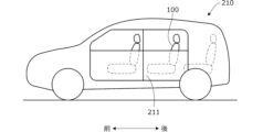
- FIG. 1B is a side view showing an example of a vehicle in which the seat of FIG. 1A is mounted.
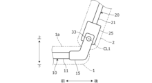
- FIG. 1A is a side view showing a schematic configuration of a connecting portion between a seat cushion frame and a seat back frame shown in FIG. 1A.
- FIG. 2 is a side view schematically showing a typical seat state obtained by the seat state changing device according to the embodiment of the present invention.
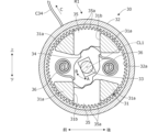
- 1 is a front view schematically showing an example of a reclining mechanism included in a seat state changing device according to an embodiment of the present invention.
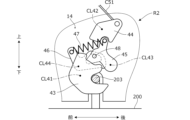
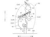
- FIG. 3 is a side view showing the configuration of a locking portion of a tumble mechanism included in a seat state changing device according to an embodiment of the present invention.
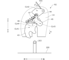
- FIG. 4B is a side view showing an example of the operation following FIG. 4A.
- FIG. 4B is a side view showing an example of the operation following FIG. 4B.
- FIG. 2 is a perspective view showing a main part configuration of an interlocking mechanism included in a seat state changing device according to an embodiment of the present invention.
- FIG. 5 is a view of arrow VI in FIG.
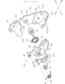
- FIG. 6 is an exploded perspective view of the interlocking mechanism shown in FIG. 5;
- FIG. 7 is a side view showing an example of the operation of the interlocking mechanism while the seat back is in the upright position to the folded position.
- FIG. 5 is a view of arrow VI in FIG.
- FIG. 6 is an exploded perspective view of the interlocking mechanism shown in FIG. 5;
- FIG. 7 is a side view showing an example of the operation of
- FIG. 8A is a side view showing an example of the operation following FIG. 8A.
- FIG. 7 is a side view showing an example of the operation when the cancel mechanism is activated.
- FIG. 8C is a side view showing an example of the operation following FIG. 8C.
- 1A is a diagram showing a connection state of a plurality of cables arranged on the sheet of FIG. 1A.
- FIG. 2 is a perspective view of the rear seat of the vehicle.
- FIG. 12 is a plan view of an armrest frame constituting the armrest of FIG. 11 and its surroundings. View XIII in FIG. 12.
- the seat state changing device is applied to a vehicle seat, which is an example of a vehicle seat.
- vehicle seat which is an example of a vehicle seat.
- the seat state changing device can be applied to other vehicle seats, and can also be applied to things other than vehicle seats.
- FIG. 1B is a side view of a vehicle 210 to which the seat 100 according to the present embodiment is applied.
- the vehicle 210 has, for example, three rows of seats in the longitudinal direction of the vehicle. Among these three rows of seats, for example, the seat 100 installed in the second row is the seat 100 in FIG. 1A.
- FIG. 1A particularly shows a seat 100 installed on the left side of the vehicle. Therefore, on the left side of the seat 100, a door 211 is provided for passengers in the second row of seats and passengers in the third row of seats to get in and out of the vehicle.
- the seat 100 is folded from the seated state shown in FIG. 1A.
- the seat installed on the right side of the vehicle can be configured laterally symmetrically with the seat 100 in FIG. 1A. Below, the configuration of each part of the seat 100 installed on the left side of the vehicle will be explained.
- the seat 100 includes a seat cushion 1 that supports the buttocks of the occupant, a seat back 2 that supports the waist and back of the occupant, and a headrest 3 that supports the head of the occupant.
- the seat cushion 1 has a seat cushion frame 10 that forms the skeleton of the seat cushion 1
- the seat back 2 has a seat back frame 20 that forms the skeleton of the seat back 2.
- the periphery of the seat cushion frame 10 is covered with a pad, and the surface of the pad is further covered with a skin.
- the periphery of the seat back frame 20 is covered with a pad, and the surface of the pad is further covered with a skin.
- the seat cushion frame 10 includes a pair of left and right side frames 11 that extend in the front-rear direction, and a pair of front and rear connection frames 12 that extend in the left-right direction and connect the left and right side frames 11 to each other.
- the seat back frame 20 includes a pair of left and right side frames 21 that extend in the vertical direction, and a pair of upper and lower connection frames 22 that extend in the left and right direction and connect the left and right side frames 21 to each other.
- support members spring members
- panels, panel members, etc. are installed in the left-right direction.
- a pair of front and rear bases (a front base 13 and a rear base 14) are provided at the lower ends of the left and right side frames 11 of the seat cushion frame 10.
- Support parts 201 and 202 are provided on the floor 200 below the seat 100 at positions corresponding to the base parts 13 and 14, respectively.
- Seat cushion frame 10 is supported by floor 200 via base portions 13 and 14 and support portions 201 and 202.
- a slide mechanism is provided between the side frame 11 and the bases 13 and 14 to support the seat cushion frame 10 so as to be slidable in the front and rear directions.
- FIG. 1C is a side view showing a schematic configuration of a connecting portion between the seat cushion frame 10 and the seat back frame 20.
- a substantially plate-shaped lower bracket 15 is fixed to the rear end portions of the left and right side frames 11 of the seat cushion frame 10 by welding or the like.
- a substantially plate-shaped upper bracket 25 is fixed to the lower ends of the left and right side frames 21 of the seat back frame 20 by welding or the like.
- a shaft portion 33 is provided to extend so as to pass through the lower bracket 15 and the upper bracket 25 in the left-right direction.
- the shaft portion 33 is located above the seat surface 1a of the seat cushion 1.
- the front base portion 13 of the seat cushion frame 10 is rotatably supported by the support portion 201 in the front-rear direction about an axis CL2 extending in the left-right direction.
- the rear base portion 14 is supported by the support portion 202 so as to be detachable from the support portion 202 .
- the seat cushion 1 rotates forward about the axis CL2 and becomes able to stand up on the floor 200.
- An operating lever 101 that can be operated upward is provided on the left side of the upper end of the seat back 2 (left side of the headrest 3), that is, on the door side.
- an operating lever 102 that can be operated forward is provided at the center of the front end of the seat cushion 1.
- the operating lever 101 may be referred to as an upper operating lever, and the operating lever 102 may be referred to as a lower operating lever.
- the upper operation lever 101 can be easily operated by an occupant who intends to enter the third row seat from the left side of the seat 100 via the door 211 (FIG. 1B), and an occupant who attempts to exit from the third row seat.
- the lower operation lever 102 can be easily operated by a passenger seated on the second row seat 100.
- FIG. 2 is a side view schematically showing a typical sheet state of the sheet 100. As shown in FIG. 2, the seat state of the seat 100 can be changed to a seated state, a forward-folded state, and a tumbled state.
- the tumble mechanism 40 further includes a lock portion R2 that locks the rear base portion 14 of the seat cushion frame 10 to the support portion 202 of the floor 200.
- a lock portion R2 that locks the rear base portion 14 of the seat cushion frame 10 to the support portion 202 of the floor 200.
- the reclining mechanism 30 includes a lower plate 31 (only the protrusions 31a are shown) that is fixed to the right end surface of the lower bracket 15 and has four protrusions 31a in the circumferential direction that protrude to the right, and an upper bracket.
- An upper plate 32 (only a substantially ring-shaped portion protruding leftward is shown) fixed to the left end surface of 25 and a shaft portion 33 (extending along axis CL1 and penetrating lower plate 31 and upper plate 32) 1C), a cam plate 34 arranged in the space between the lower plate 31 and the upper plate 32 and rotating together with the shaft part 33, a pair of upper and lower locking members 35 arranged in the space, and a cam plate 34 in the direction of arrow A.
- the lower plate 31, the upper plate 32, and the shaft portion 33 are shown by hatching for convenience to distinguish them from other parts.
- the cam plate 34 engages with the lock member 35, and when the cam plate 34 rotates in the direction of arrow A due to the urging force of the torsion spring 36 as shown, the lock member 35 moves radially outward.
- the external teeth 35a mesh with the internal teeth 32a, and the rotational position of the upper bracket 25 with respect to the lower bracket 15 is fixed (reclining lock). That is, the lock member 35 constitutes a lock portion R1 (FIG. 2), and the seat back 2 can be fixed at any rotational position via the lock member 35.
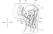
- the interlocking mechanism 50 includes a base plate 51 fixed to the left end surface of the lower bracket 15, a rotation plate 52 rotatably attached to the left end surface of the base plate 51, and It has a lever plate 53 rotatably attached to the left end surface of the plate 52 and a pressing plate 54 fixed to the left end surface of the upper bracket 25.
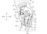
- FIG. 5 shows the configuration of the interlocking mechanism 50 in the seated state of the seat 100, and corresponds to the initial state of the interlocking mechanism 50 in which the pin 58 and the contact portion 544 are separated.
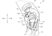
- FIG. 8A is a side view showing an example of the operation of the interlocking mechanism 50 while the seat back 2 is in the process of changing from the upright position to the folded position.
- the cable support portion 513 of the base plate 51 supports an end portion of a cylindrical outer 515 that covers the cables C51 to C53.
- the distal end portions of the cables C51 and C52 are respectively connected to a pair of front and rear cable connecting portions 525 provided on the rotation plate 52.
- the tip of the cable C53 is connected to a cable connecting portion 534 provided on the lever plate 53.
- the cables C51 to C53 extend in the vertical direction so as not to cross each other, and are arranged spaced apart from each other in the front-back direction.
- the cables C51 to C53 are movable within the outer 515, and the length from the tip of the outer 515 to the tip of the cables C51 to C53 changes as the seat back frame 20 rotates.
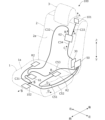
- FIG. 9 is a diagram showing the connection state of a plurality of cables arranged on the seat 100.
- An outer 515 as shown in FIG. 8A is provided around each cable, but illustration of the outer 515 is omitted in FIG. 9.
- one end of the cable C31 is connected to the lower operating lever 102 provided at the front end of the seat cushion 1.
- the other end of the cable C31 is connected to a cushion relay section 61 arranged inside the seat cushion 1.
- one end portions of cables C32 and C53 are connected to the cushion relay portion 61.
- the other end of the cable C53 is connected to the interlocking mechanism 50 (FIG. 8A). Furthermore, one end portions of cables C51 and C52 are connected to the interlocking mechanism 50. The other end of the cable C51 is connected to the lock portion R2 on the left side of the seat 100 (see FIG. 4A). The other end of the cable C52 is connected to the lock portion R2 on the right side of the seat 100.
- the cushion relay section 61 has a function of transmitting the tensile force acting on the cable C31 to the cables C32 and C53.
- the cushion relay part 61 has a cushion rotation plate (not shown) that rotates around an axis extending in the vertical direction, and the ends of the cables C31, C32, and C53 are connected to the cushion rotation plate. Each is connected.
- the cushion rotating plate rotates, thereby pulling the cables C32 and C53 in the direction of arrow B.
- the state of the interlocking mechanism 50 is in the initial state shown in FIG. 5.
- the rotating position of the rotating plate 52 is the locking position, the cables C51 and C52 in FIG. 9 are not pulled, and the locking portion R2 of the tumble mechanism 40 is operating.
- the contact portion 544 of the pressing plate 54 does not contact the pin 58, and the rotational position of the rotation plate 52 remains in the same position as the initial state (FIG. 5), and the locking operation is performed. held in position. Therefore, the release operation of the locking portion R2 by the interlocking mechanism 50 is canceled (invalidated), and the seat cushion 1 is maintained in a horizontal position without releasing the locking portion R2.
- the cable C53, lever plate 53, etc. in FIG. 8C constitute a canceling mechanism 70 for making it possible to cancel the release operation of the lock portion R2.
- the seat state can be shifted from the seated state to the forward-folded state and then to the tandem state. Furthermore, by operating the lower operating lever 102 provided at the front end of the seat cushion 1, the seat state can be shifted from the seated state to the forward-folded state. Therefore, by operating the different operating levers 101 and 102, the seat state can be changed to a mutually different seat state, and a variety of seat arrangements can be easily realized.
- the seat state changing device includes a seat cushion 1 that is provided so as to be able to change its posture between a horizontal posture extending in a substantially horizontal direction and a vertical posture extending in a substantially vertical direction, and a seat cushion centered on an axis CL1.
- a seat back 2 is provided so as to be rotatable to the seat cushion 1, and is also provided so as to be changeable between an upright position in which the seat cushion 1 is in a horizontal position and a folded position in which it is tilted toward the seat cushion 1 in a horizontal position. (FIG. 1A).
- the seat cushion 1 has a seat cushion frame 10, and the seat back 2 is rotatably supported by the seat cushion frame 10 about an axis CL1, and is provided with an abutment portion 544. It has a seat back frame 20 (FIGS. 1A and 5).
- the interlocking mechanism 50 includes a lever plate 53 provided with a pin 58 that the contact portion 544 contacts when the seat back 2 is tilted, and a rotating plate 52 that supports the lever plate 53. When the lever plate 53 comes into contact with the pin 58 and the lever plate 53 is pushed, the lock portion R2 is configured to be released (FIGS. 8B and 9).
- the canceling mechanism 70 receives the operating force of the lower operating lever 102 and moves the pin 58 to a retracted position where the contact portion 544 and the pin 58 are prevented from contacting each other (FIG. 8C). Thereby, by moving the lever plate 53 that constitutes the interlocking mechanism 50 to the retracted position, the release of the lock portion R2 can be disabled. Therefore, the configuration of the cancel mechanism 70 can be simplified, and an increase in the number of parts due to the addition of the cancel mechanism 70 can be minimized.
- the interlocking mechanism 50 includes a rotation plate 52 that is rotatable about the axis CL1 from a lock operation position where the lock portion R2 is activated to an unlock position where the lock portion R2 is released;
- a lever plate 53 is rotatably supported by the rotation plate 52 about an axis CL5 substantially parallel to the axis CL1 so as to rotate together with the rotation plate 52, and has a pin 58. (Figure 5).
- the lever plate 53 is provided so that the pin 58 moves from an abutting position where it can abut the abutting portion 544 to a retracted position in response to the operating force of the operating lever 102 (FIGS. 8A and 8C).
- the interlocking mechanism 50 and the canceling mechanism can be configured compactly and can be easily incorporated into the seat 100.
- the reclining mechanism 30 has a cable C34 that transmits the operating force of the lower operating lever 102 to the lock portion R1 (FIGS. 3 and 9).
- the cancel mechanism 70 has a cable C53 that transmits the operating force of the lower operating lever 102 to the lever plate 53 (FIGS. 8C and 9).
- the upper operating lever 101 is provided at the upper end of the seat back 2 (FIG. 1A). Thereby, an occupant who is going to get on the rear seat of the seat 100 and an occupant who has got on the seat can easily operate the seat 100.
- the seat state changes to a tandem state, making it easy for the passenger in the rear seat to get on and off the vehicle.
- the lower operation lever 102 is provided at the front end of the seat cushion 1 on the opposite side of the axis CL1 (FIG. 1A). This can prevent the occupant in the rear seat of the seat 100 from accidentally operating the lower operating lever 102.
- the lower operation lever 102 can also be provided on the side surface of the seat cushion 1 (FIGS. 10A and 10B). Thereby, the number of cables that transmit the operating force of the lower operating lever 102 can be reduced.
- the seat 100 is configured so that the seat state can be changed to the seated state (first state), the forward-folded state (second state), and the tumble state (third state). It may also be possible to change to another state (for example, a fully flat state).
- the seat back 2 is brought into the folded position by the urging force of the spring S1, but the configuration of the first urging section is not limited to that described above.
- a cylinder member filled with gas or the like may be used.
- the seatback 2 is fixed in the upright position by the locking portion R1 of the reclining mechanism 30 against the biasing force of the spring S1, but the configuration of the first locking portion is the same as that described above. Not limited to things.
- the interlocking mechanism 50 rotates about the axis CL1 (first axis) from the locking position (FIG. 5) where the locking portion R2 is activated to the unlocking position (FIG. 8B) where the locking portion R2 is released.
- a rotating plate 52 (first rotating member) is provided to be rotatable around an axis CL5 (second axis) so as to rotate together with the rotating plate 52.
- a lever plate 53 (second rotating member) is movably supported and has a pin 58 as a contact portion.
- the interlocking mechanism 50 includes a rotatable movable portion (a rotary plate 52, a lever plate 53), the movable part is not limited to being rotatable but may be movable, and the configuration of the movable part is not limited to that described above.
- the movable part may be composed of a single member.
- the operating force of the lower operation lever 102 is transmitted to the locking part R1 (reclining mechanism 30) via the cables C31, C32, C34 (first power transmission part), and the cables C31, C53
- the operating force of the lower operating lever 102 is transmitted to the lever plate 53 via the second power transmitting section (second power transmitting section)
- the configurations of the first power transmitting section and the second power transmitting section are not limited to those described above. .
- the seat 100 is applied to the vehicle 210 (FIG. 1B). Therefore, the present invention can also be configured as a vehicle having the seat 100. Further, the seat 100 can also be applied to vehicles other than vehicles, such as aircraft and ships. Therefore, the seat 100 can be used as a vehicle seat.
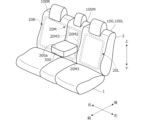
- FIG. 11 is a perspective view showing a schematic configuration of the second row seat of the vehicle 210.
- FIG. 11 also shows the main part configuration of the seat back frame 20 (20L, 20M, 20R) (dotted line).
- the second row of seats includes the aforementioned left seat 100 (indicated by reference numeral 100L), right seat 100R, and center seat 100M.
- the left seat 100L is provided with a seat back frame 20L
- the right seat 100R is provided with a seat back frame 20R
- the center seat 100M is provided with a seat back frame 20M.
- the seat back frame 20L is separated from the seat back frame 20M, and the seat back frame 20R is coupled to the seat back frame 20M. Therefore, the seat state of the left seat 100L can be changed independently, whereas the seat state of the right seat 100R is changed integrally with the center seat 100M.
- FIG. 11 shows the use position of the armrest 300 in which the armrest 300 is rotated downward to the maximum extent.
- a recess is provided on the upper surface 300a of the armrest 300 in the use position.
- the recessed portion is used as a drink holder, storage space, etc.
- a recess (not shown) for storing the armrest 300 is provided on the front surface of the seat back 2 of the center seat 100M.
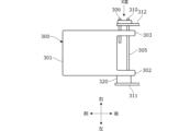
- FIG. 12 is a plan view (view from above) of the armrest 300 in the use position.
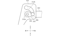
- FIG. 12 mainly shows the configuration of the support portion of the armrest frame 301 that forms the skeleton of the armrest 300 and the surrounding portion thereof.
- a pair of left and right support parts 302 and 303 are provided at the rear end of the armrest frame 301 to protrude rearward.
- the support parts 302 and 303 are provided with a rotation shaft 305 that penetrates the support parts 302 and 303 and extends in the left-right direction so as to be rotatable together with the support parts 302 and 303.
- a pair of left and right brackets 311 and 312 are provided on both left and right ends of the connection frame 20M1 (FIG. 11) to protrude upward and forward. Both left and right ends of the rotation shaft 305 are rotatably supported by the brackets 311 and 312, respectively. This allows the armrest frame 301 to rotate in the vertical direction about the rotation axis 305.
- the armrest 300 is supported in a double-sided structure via the pair of left and right brackets 311 and 312, so the support rigidity is increased and the large armrest 300 can be stably supported.
- the armrest 300 is supported in a cantilever structure via one of the left and right brackets (for example, the bracket 311), it is necessary to increase the size of the bracket 311 in order to increase the support rigidity of the armrest 300.
Landscapes
- Engineering & Computer Science (AREA)
- Aviation & Aerospace Engineering (AREA)
- Transportation (AREA)
- Mechanical Engineering (AREA)
- Seats For Vehicles (AREA)
Abstract
Description
(1)シート状態変更装置は、略水平方向に延在する水平姿勢と略鉛直方向に延在する鉛直姿勢とに姿勢変更可能に設けられたシートクッション1と、軸線CL1を中心にしてシートクッション1に回動可能に設けられるとともに、水平姿勢であるシートクッション1から起立した起立姿勢と水平姿勢であるシートクッション1に向けて倒回した折り畳み姿勢とに姿勢変更可能に設けられたシートバック2と、を有するシート100を所定のシート状態に変更するように構成される(図1A)。所定のシート状態は、シートクッション1が水平姿勢で、かつ、シートバック2が起立姿勢である着座状態と、シートクッション1が水平姿勢で、かつ、シートバック2が折り畳み姿勢である前倒し状態と、シートクッション1が鉛直姿勢で、かつ、シートバック2が折り畳み姿勢であるタンブル状態と、を含む(図2)。シート状態変更装置は、シートバック2が折り畳み姿勢となるようにシートバック2を付勢するばねS1と、ばねS1の付勢力に抗してシートバック2を起立姿勢に固定するロック部R1と、シートクッション1が鉛直姿勢となるようにシートクッション1を付勢するばねS2と、ばねS2の付勢力に抗してシートクッション1を水平姿勢に固定するロック部R2と、ユーザがそれぞれ操作力を入力する上部操作レバー101および下部操作レバー102と、上部操作レバー101の操作力または下部操作レバー102の操作力を受けて、ロック部R1を解除するリクライニング機構30と、ロック部R1の解除によるシートバック2の倒回に伴い、ロック部R2を解除する連動機構50と、下部操作レバー102の操作力を受けて、シートバック2の倒回に伴う連動機構50によるロック部R2の解除を無効化するキャンセル機構70と、を備える(図2,図8C,図9)。
Claims (11)
- 略水平方向に延在する水平姿勢と略鉛直方向に延在する鉛直姿勢とに姿勢変更可能に設けられたシートクッションと、軸線を中心にして前記シートクッションに回動可能に設けられるとともに、前記水平姿勢である前記シートクッションから起立した起立姿勢と前記水平姿勢である前記シートクッションに向けて倒回した折り畳み姿勢とに姿勢変更可能に設けられたシートバックと、を有するシートを所定のシート状態に変更するシート状態変更装置であって、
前記所定のシート状態は、前記シートクッションが前記水平姿勢で、かつ、前記シートバックが前記起立姿勢である第1状態と、前記シートクッションが前記水平姿勢で、かつ、前記シートバックが前記折り畳み姿勢である第2状態と、前記シートクッションが前記鉛直姿勢で、かつ、前記シートバックが前記折り畳み姿勢である第3状態と、を含み、
前記シートバックが前記折り畳み姿勢となるように前記シートバックを付勢する第1付勢部と、
前記第1付勢部の付勢力に抗して前記シートバックを前記起立姿勢に固定する第1ロック部と、
前記シートクッションが前記鉛直姿勢となるように前記シートクッションを付勢する第2付勢部と、
前記第2付勢部の付勢力に抗して前記シートクッションを前記水平姿勢に固定する第2ロック部と、
ユーザがそれぞれ操作力を入力する第1操作部材および第2操作部材と、
前記第1操作部材の操作力または前記第2操作部材の操作力を受けて、前記第1ロック部を解除する第1ロック解除機構と、
前記第1ロック部の解除による前記シートバックの倒回に伴い、前記第2ロック部を解除する第2ロック解除機構と、
前記第2操作部材の操作力を受けて、前記シートバックの倒回に伴う前記第2ロック解除機構による前記第2ロック部の解除を無効化するキャンセル機構と、を備えることを特徴とするシート状態変更装置。 - 請求項1に記載のシート状態変更装置において、
前記シートクッションは、シートクッションフレームを有し、
前記シートバックは、前記軸線を中心にして前記シートクッションフレームに回動可能に軸支されるとともに、当接部が設けられたシートバックフレームを有し、
前記第2ロック解除機構は、前記シートバックの倒回に伴い前記当接部が当接する被当接部が設けられた可動部を有し、前記当接部が前記被当接部に当接して前記可動部が移動されると、前記第2ロック部が解除するように構成され、
前記キャンセル機構は、前記第2操作部材の操作力を受けて、前記被当接部を、前記当接部と前記被当接部との当接を避ける退避位置へ移動させることを特徴とするシート状態変更装置。 - 請求項2に記載のシート状態変更装置において、
前記軸線は第1軸線であり、
前記可動部は、
前記第2ロック部が作動するロック作動位置から前記第2ロック部が解除されるロック解除位置へと、前記第1軸線を中心にして回動可能に設けられた第1回動部材と、
前記第1回動部材と一体に回動するように前記第1軸線と略平行な第2軸線を中心にして前記第1回動部材に回動可能に軸支されるとともに、前記被当接部を有する第2回動部材と、を有し、
前記第2回動部材は、前記第2操作部材の操作力を受けて、前記被当接部が、前記当接部と当接可能な当接可能位置から前記退避位置へ移動するように設けられることを特徴とするシート状態変更装置。 - 請求項3に記載のシート状態変更装置において、
時計回りおよび反時計回りの一方および他方をそれぞれ第1方向および第2方向とするとき、前記第1回動部材が前記ロック作動位置から前記ロック解除位置へ回動される方向は前記第1方向であり、
前記被当接部が前記当接可能位置から前記退避位置へ移動するときの前記第2回動部材の回動方向は前記第2方向であることを特徴とするシート状態変更装置。 - 請求項3または4に記載のシート状態変更装置において、
前記第1ロック解除機構は、前記第2操作部材の操作力を前記第1ロック部に伝達する第1動力伝達部を有し、
前記キャンセル機構は、前記第2操作部材の操作力を前記第2回動部材に伝達する第2動力伝達部を有することを特徴とするシート状態変更装置。 - 請求項1~5のいずれか1項に記載のシート状態変更装置において、
前記第1操作部材は、前記シートバックの上端に設けられることを特徴とするシート状態変更装置。 - 請求項1~6のいずれか1項に記載のシート状態変更装置において、
前記軸線は、前記シートクッションの一端部に位置し、
前記第2操作部材は、前記シートクッションの他端部に設けられることを特徴とするシート状態変更装置。 - 請求項1~6のいずれか1項に記載のシート状態変更装置において、
前記第2操作部材は、前記シートクッションの側面に設けられることを特徴とするシート状態変更装置。 - 請求項1~6のいずれか1項に記載のシート状態変更装置において、
前記第2操作部材は、前記軸線を中心に回動可能に設けられることを特徴とするシート状態変更装置。 - 請求項1~9のいずれか1項に記載のシート状態変更装置を備える乗り物用シート。
- 請求項10に記載の乗り物用シートを備える車両。
Priority Applications (1)
| Application Number | Priority Date | Filing Date | Title |
|---|---|---|---|
| JP2024528975A JPWO2023243713A1 (ja) | 2022-06-17 | 2023-06-16 |
Applications Claiming Priority (2)
| Application Number | Priority Date | Filing Date | Title |
|---|---|---|---|
| US202263366543P | 2022-06-17 | 2022-06-17 | |
| US63/366,543 | 2022-06-17 |
Publications (1)
| Publication Number | Publication Date |
|---|---|
| WO2023243713A1 true WO2023243713A1 (ja) | 2023-12-21 |
Family
ID=89191467
Family Applications (1)
| Application Number | Title | Priority Date | Filing Date |
|---|---|---|---|
| PCT/JP2023/022411 Ceased WO2023243713A1 (ja) | 2022-06-17 | 2023-06-16 | シート状態変更装置、乗り物用シートおよび車両 |
Country Status (2)
| Country | Link |
|---|---|
| JP (1) | JPWO2023243713A1 (ja) |
| WO (1) | WO2023243713A1 (ja) |
Citations (3)
| Publication number | Priority date | Publication date | Assignee | Title |
|---|---|---|---|---|
| WO2008102506A1 (ja) * | 2007-02-23 | 2008-08-28 | Toyota Boshoku Kabushiki Kaisha | 車両用シート |
| JP2011245990A (ja) * | 2010-05-27 | 2011-12-08 | Shiroki Corp | 座席シート |
| JP2019172119A (ja) * | 2018-03-29 | 2019-10-10 | トヨタ紡織株式会社 | 乗物用シートのロック装置 |
-
2023
- 2023-06-16 JP JP2024528975A patent/JPWO2023243713A1/ja not_active Withdrawn
- 2023-06-16 WO PCT/JP2023/022411 patent/WO2023243713A1/ja not_active Ceased
Patent Citations (3)
| Publication number | Priority date | Publication date | Assignee | Title |
|---|---|---|---|---|
| WO2008102506A1 (ja) * | 2007-02-23 | 2008-08-28 | Toyota Boshoku Kabushiki Kaisha | 車両用シート |
| JP2011245990A (ja) * | 2010-05-27 | 2011-12-08 | Shiroki Corp | 座席シート |
| JP2019172119A (ja) * | 2018-03-29 | 2019-10-10 | トヨタ紡織株式会社 | 乗物用シートのロック装置 |
Also Published As
| Publication number | Publication date |
|---|---|
| JPWO2023243713A1 (ja) | 2023-12-21 |
Similar Documents
| Publication | Publication Date | Title |
|---|---|---|
| JP4305675B2 (ja) | 車両用シート | |
| US8162404B2 (en) | Seat | |
| WO2007086468A1 (ja) | シート | |
| CA2645752C (en) | Folding head restraint | |
| US7828382B2 (en) | Vehicle seat having an operation lever arrangement structure | |
| KR20010040787A (ko) | 일체형 아동용 시트를 구비한 용이 접근 텀블형 시트 및아동용 시트가 전개될 때의 텀블형 로크아웃부 | |
| JP2009090809A (ja) | 車両用格納シート | |
| GB2382983A (en) | Vehicle seat system | |
| WO2014171454A1 (ja) | 車両用シート | |
| JP5647437B2 (ja) | 座席シート | |
| JP6039457B2 (ja) | オットマン装置及び車両用シート | |
| JP2009539686A (ja) | 車両シートバックにおける又は車両シートバックに関する改良 | |
| JP5727222B2 (ja) | シートフレーム及び該シートフレームを備えた車両用格納シート | |
| JP5125656B2 (ja) | 車両用シート | |
| JP5141352B2 (ja) | 車両用シート | |
| JP2001001808A (ja) | シートスライド装置のロック機構 | |
| JP5481802B2 (ja) | 車両用シート | |
| JP2007062636A (ja) | 車両用シート | |
| JP7741414B2 (ja) | 車両用シート | |
| JP2011073621A (ja) | 折り畳みシート装置 | |
| JP3762534B2 (ja) | ヘッドレスト装置 | |
| JP2003002098A (ja) | 車両用折りたたみシート | |
| JP2013001175A (ja) | 車両用シート | |
| JP2009061834A (ja) | 車両用格納シート | |
| JPH0891101A (ja) | 可倒式リヤシートバックのロック機構 |
Legal Events
| Date | Code | Title | Description |
|---|---|---|---|
| 121 | Ep: the epo has been informed by wipo that ep was designated in this application |
Ref document number: 23824003 Country of ref document: EP Kind code of ref document: A1 |
|
| WWE | Wipo information: entry into national phase |
Ref document number: 2024528975 Country of ref document: JP |
|
| WWE | Wipo information: entry into national phase |
Ref document number: 2401008199 Country of ref document: TH |
|
| NENP | Non-entry into the national phase |
Ref country code: DE |
|
| 122 | Ep: pct application non-entry in european phase |
Ref document number: 23824003 Country of ref document: EP Kind code of ref document: A1 |