WO2023243441A1 - コネクタユニット - Google Patents
コネクタユニット Download PDFInfo
- Publication number
- WO2023243441A1 WO2023243441A1 PCT/JP2023/020635 JP2023020635W WO2023243441A1 WO 2023243441 A1 WO2023243441 A1 WO 2023243441A1 JP 2023020635 W JP2023020635 W JP 2023020635W WO 2023243441 A1 WO2023243441 A1 WO 2023243441A1
- Authority
- WO
- WIPO (PCT)
- Prior art keywords
- mating
- housing
- connector
- hood
- terminal
- Prior art date
- Legal status (The legal status is an assumption and is not a legal conclusion. Google has not performed a legal analysis and makes no representation as to the accuracy of the status listed.)
- Ceased
Links
Images




Classifications
-
- H—ELECTRICITY
- H01—ELECTRIC ELEMENTS
- H01R—ELECTRICALLY-CONDUCTIVE CONNECTIONS; STRUCTURAL ASSOCIATIONS OF A PLURALITY OF MUTUALLY-INSULATED ELECTRICAL CONNECTING ELEMENTS; COUPLING DEVICES; CURRENT COLLECTORS
- H01R13/00—Details of coupling devices of the kinds covered by groups H01R12/70 or H01R24/00 - H01R33/00
- H01R13/46—Bases; Cases
- H01R13/533—Bases, cases made for use in extreme conditions, e.g. high temperature, radiation, vibration, corrosive environment, pressure
Definitions
- the present disclosure relates to a connector unit.
- the connector includes a plurality of female terminal fittings, a housing, a retainer, and a seal member.
- the housing is made of synthetic resin and includes a housing body portion having a plurality of cavities into which a plurality of female terminal fittings can be inserted, a cylindrical fitting tube portion surrounding the outer periphery of the housing body portion, and a fitting tube portion. A connecting portion extending in the radial direction and connecting to the housing main body portion.
- the portion of the housing main body located on the rear side across the connecting portion has a chained cylindrical cavity tower portion that partitions each cavity and continues in a row from left to right.
- the female terminal fitting has a wire barrel portion connected to the end portion of the electric wire, and an insulation barrel portion crimped and connected to an individual rubber stopper fitted onto the outside of the electric wire.
- the rubber stopper is housed in a compressed state within the cavity tower section.
- a mating connector that can be fitted to the above connector includes a plurality of male terminal fittings and a mating housing.
- the mating housing is made of synthetic resin and has a cylindrical hood that projects forward.
- the hood part is fitted between the fitting cylinder part and the housing main body part, and the male terminal fitting and the female terminal fitting are electrically connected.
- the wire accommodating part protrudes rearward from the tip of the hood part fitted between the mating cylinder part and the housing main body part, so the overall center of gravity of the connector and the mating connector is at the rear of the connector.
- the displacement of the rear end of the connector becomes large during resonance. That is, if the portion of the housing that is not fitted with the hood portion of the mating connector is large in the fitted state, that portion is likely to be displaced during resonance.
- the vibrations of the mating connector and the connector are likely to be integrated, so that displacement can be easily suppressed even during resonance. As described above, there is room for further improvement in improving the vibration resistance of the connector.
- a connector unit of the present disclosure includes a mating connector having a mating housing, and a connector having a housing that can be fitted into the mating housing, wherein the mating housing and the housing are fitted into each other.
- the mating housing opens forward.
- the housing has a hood part that can be fitted externally to the hood part of the other party, a tower part that can be fitted internally to the hood part of the other party, and a rear end of the hood part and the tower part.
- the tower part has a terminal accommodating part that protrudes forward from the front end of the hood part and accommodates a terminal therein, and a terminal accommodating part that protrudes forward from the front end of the hood part, and a rear part of the terminal accommodating part.
- an electric wire accommodating part connected to the side and accommodating therein an electric wire connected to the terminal, and when the counterpart housing and the housing are fitted, the counterpart hood part is connected to the electric wire accommodating part.
- the connector unit is arranged so as to surround the outer periphery of the connector unit, and the front end of the mating hood portion is located at the rear end portion of the housing.
- the vibration resistance of the connector unit can be improved.
- FIG. 1 is a perspective view of the connector unit.
- FIG. 2 is an exploded perspective view of the connector unit.
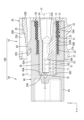
- FIG. 3 is a longitudinal sectional view showing the internal structure of the connector unit.
- FIG. 4 is a cross-sectional view showing the internal structure of the connector unit.
- FIG. 5 is a front view of the connector.
- FIG. 6 is a side view of the connector.
- FIG. 7 is a front view of the mating connector.
- a connector unit of the present disclosure includes a mating connector having a mating housing and a connector having a housing that can be fitted into the mating housing, the connector unit including the mating housing and the mating housing.
- the mating surface of the mating housing and the mating surface of the housing face each other, and when the mating surfaces of each other are defined as the front side, the mating housing faces forward.
- the housing has a mating hood part that opens, and the housing includes a hood part that can be fitted externally to the mating hood part, a tower part that can be fitted internally to the mating hood part, a rear end of the hood part, and a tower part that can be fitted internally to the mating hood part.
- a connecting part connecting the rear end of the tower part, the tower part has a terminal accommodating part that protrudes forward from the front end of the hood part and accommodates the terminal therein; an electric wire accommodating part that is connected to the rear side of the part and stores therein an electric wire connected to the terminal, and when the mating housing and the housing are fitted together, the mating hood part is connected to the housing.
- the connector unit is arranged to surround the outer periphery of the wire accommodating part, and the front end of the mating hood part is located at the rear end part of the housing.
- the terminal accommodating portion projects forward beyond the front end of the hood portion, and the front end of the mating hood portion is located at the rear end of the housing, so the center of gravity of the entire connector unit is It can be positioned further forward than before. As a result, displacement of the entire connector unit during resonance can be suppressed more than in conventional connector units.
- the dimension of the part of the housing that protrudes rearward from the front end of the mating hood is the sum of the plate thickness of the connecting part and the length of the wire accommodating part in the front and rear direction.
- the mating hood part is arranged to surround the outer periphery of the wire accommodating part, so the size of the part of the housing that protrudes rearward from the front end of the mating hood part in the mated state. Since this is only the plate thickness of the connecting portion, it is possible to suppress the amount of rearward protrusion, and it is possible to suppress the amount of displacement of the rear end of the connector from increasing during resonance.
- the hood part has a cylindrical shape that opens forward, and that the opening edge of the hood part is provided with a thickened part that increases the thickness outward in the radial direction. Since the thickened portion is provided at the opening edge of the hood portion, the center of gravity of the entire connector unit can be positioned further forward.
- the thickened portion has a waiting portion that becomes thicker toward the front. Since the thickened part has the handheld part, when fitting the connector to the mating connector, fingers can easily catch on the handheld part, and the thickened part can be used as an operating part during fitting. Furthermore, compared to the case where the handheld portion is provided at the rear end of the housing, the center of gravity of the entire connector unit can be positioned forward, so that vibration resistance can be further improved.
- the connector unit 100 of this embodiment includes a mating connector 50 having a mating housing 60 and a connector 10 having a housing 20 that can be fitted into the mating housing 60.
- the direction shown by arrow Z is the up-down direction
- the direction shown by arrow X is the front-back direction
- the direction shown by arrow Y is the left-right direction.
- the connector 10 of this embodiment includes a housing 20 and a rubber plug 30.
- the connector 10 can be fitted with a mating connector 50.
- the mating surface 60A of the mating housing 60 and the mating surface 20A of the housing 20 face each other in the front-rear direction,
- the mating surfaces 20A and 60A sides are defined as the front side. Note that in the case of a plurality of identical members, only some of the members may be labeled with reference numerals, and the reference numerals of other members may be omitted.
- the mating connector 50 includes a mating housing 60 and a mating terminal 51.
- the mating housing 60 is made of insulating synthetic resin, and as shown in FIG. It includes a rear cylindrical portion 63 extending rearward from the periphery.
- the front cylinder part 62 has a cylindrical hood shape and is open to the front, and the back wall of the front cylinder part 62 is constituted by the main body part 61.
- the rear cylindrical portion 63 has a cylindrical hood shape and is open to the rear, and the back wall of the rear cylindrical portion 63 is constituted by the main body portion 61.
- the front cylindrical portion 62, the main body portion 61, and the rear cylindrical portion 63 are provided in series in this order.
- the outer circumferential surface 62A of the front cylindrical portion 62, the outer circumferential surface 61A of the main body portion 61, and the outer circumferential surface 63A of the rear cylindrical portion 63 are continuous so as to be flush with each other.
- a lock receiving portion 64 is provided on the outer peripheral surface 62A of the front cylinder portion 62.
- a pair of protective walls 65 are provided on both left and right sides of the lock receiving part 64 on the outer peripheral surface 62A of the front cylinder part 62.
- a pair of flange portions 66 are provided at the rear end of the rear cylinder portion 63 so as to protrude in the left-right direction.
- the mating terminal 51 is made of metal and is a tab-shaped male terminal as shown in FIGS. 3 and 4.
- the mating terminal 51 is formed into a predetermined shape by a known method such as press working, cutting, casting, etc.
- the metal constituting the mating terminal 51 can be appropriately selected from copper, copper alloy, aluminum, aluminum alloy, stainless steel, or any other metal as necessary.
- a plating layer may be formed on the surface of the mating terminal 51.
- any metal such as tin, nickel, silver, etc. can be appropriately selected as necessary.
- the mating terminal 51 is held by the main body 61 in a manner that it passes through the main body 61 of the mating housing 60 in the front-rear direction.
- a portion of the mating terminal 51 that corresponds to the front tube portion 62 protrudes from the main body portion 61 to approximately one-third of the total length of the front tube portion 62 in the front-rear direction.
- a portion of the mating terminal 51 that corresponds to the rear cylindrical portion 63 protrudes from the main body 61 to the rear beyond the opening edge of the rear cylindrical portion 63.
- the connector 10 includes a housing 20, a terminal 11, and a rubber stopper 30.
- the housing 20 is made of insulating synthetic resin, and as shown in FIG. It includes a tower portion 23 extending forward from the portion 21 and a lock arm 25 provided on the upper surface of the connecting portion 21.
- the connecting portion 21 connects the rear end of the hood portion 22 and the rear end of the tower portion 23.
- the hood portion 22 fits externally into the front cylindrical portion 62 of the mating housing 60, and the tower portion 23 fits internally into the front cylindrical portion 62 of the mating housing 60.
- the terminal 11 is a rectangular tube-shaped female terminal made of metal.
- the terminal 11 is formed into a predetermined shape by a known method such as press working, cutting, casting, etc.
- the metal constituting the terminal 11 can be appropriately selected from copper, copper alloy, aluminum, aluminum alloy, stainless steel, or any other metal as required.
- a plating layer may be formed on the surface of the terminal 11. As the metal constituting the plating layer, any metal such as tin, nickel, silver, etc. can be appropriately selected as necessary.
- the hood portion 22 has a cylindrical hood shape and is open toward the front.
- the back wall of the hood portion 22 is constituted by the connecting portion 21.
- a portion of the hood portion 22 that corresponds to the lock arm 25 bulges upward and is cut out leaving the front end, and the entire lock arm 25 is accommodated in this bulged portion. Therefore, the hood portion 22 has a pair of protective walls 22A disposed on both left and right sides of the lock arm 25.
- the tower portion 23 has a substantially rectangular shape that is long in the left and right direction when viewed from the front.
- the tower portion 23 includes at least a pair (three in the present disclosure) of cavities 23A that are open in the front-rear direction, and a partition wall 23B that partitions between the adjacent pair of cavities 23A.
- the tower section 23 includes a terminal accommodating section 26 that accommodates the terminal 11 therein, and a wire accommodating section 24 that is connected to the rear side of the terminal accommodating section 26 and that accommodates the electric wire 12 connected to the terminal 11 therein. It is configured.
- the cavity 23A and the partition wall 23B are provided from the front end of the terminal accommodating part 26 to the rear end of the wire accommodating part 24.
- the electric wire accommodating portion 24 accommodates the electric wire 12 connected to the terminal 11 and the rubber stopper 13 fitted onto the electric wire 12.
- the electric wire 12 has a well-known configuration in which a conductive single-core wire or a core wire made of a thin metal wire is surrounded by an insulating coating.
- the cavity 23A of the tower section 23 is watertight by being held between the insulating coating of the electric wire 12 and the inner peripheral surface of the electric wire accommodating section 24.
- a lance 26A is formed on the bottom wall of the terminal accommodating portion 26.
- the lance 26A has a cantilever shape extending forward.
- the lance 26A is bent and deformed downward, and when the terminal 11 is inserted into the normal position in the terminal accommodating part 26, the lance 26A returns to its original shape and the terminal 11 It is designed to be locked in place. Thereby, the terminal 11 is held in the terminal accommodating portion 26 in the cavity 23A.
- the lock arm 25 includes a pair of base end portions 25A each connected to a pair of protection walls 22A, an arm portion 25B that can swing around the pair of base end portions 25A, and an arm portion. It includes a locking part 25C formed at the front end of the arm part 25B, and a release operation part 25D formed at the rear end of the arm part 25B.
- the arm portion 25B is connected to a pair of base end portions 25A at a position closer to the rear end than the center thereof.
- the locking portion 25C rides on the lock receiving portion 64, causing the arm portion 25B to elastically swing, and the locking portion 25C rides over the lock receiving portion 64. Then, the arm portion 25B returns elastically, and the locking portion 25C locks onto the lock receiving portion 64. Thereby, the connector 10 and the mating connector 50 are maintained in a fitted state.
- the rubber stopper 30 is an elastic member made of synthetic rubber, natural rubber, or the like, and is formed into a rectangular ring shape with rounded corners, as shown in FIG.
- the rubber stopper 30 includes a cylindrical water stop portion 32 and a cylindrical anti-vibration portion 33 extending forward from the water stop portion 32. As shown in FIG. 3 , the water stop portion 32 is fitted onto the wire accommodating portion 24 of the tower portion 23 , and the vibration proof portion 33 is fitted onto the terminal accommodating portion 26 of the tower portion 23 .
- the water stop portion 32 has a lip 31 that is formed seamlessly in the circumferential direction of the water stop portion 32.
- a plurality of lips 31 are provided side by side in the front-rear direction. As shown in FIG. 3, the lip 31 has a portion that projects radially outward from the outer peripheral surface of the water stop portion 32 and a portion that projects radially inward from the inner peripheral surface of the water stop portion 32.
- the lip 31 comes into close contact with both the inner circumferential surface 62B of the front cylindrical portion 62 and the outer circumferential surface 24A of the wire accommodating portion 24, so that water is cut off between the front cylindrical portion 62 and the tower portion 23. There is.
- the vibration-proof portion 33 is formed in a cylindrical shape extending forward from the water stop portion 32 along the outer circumferential surface 26B of the terminal accommodating portion 26.
- the front end of the vibration-proof portion 33 is located at approximately one-half of the total length of the terminal accommodating portion 26 in the front-rear direction.
- the vibration-proof portion 33 suppresses the vibration. Thereby, it is possible to suppress the contacts between the terminal 11 and the mating terminal 51 from being worn out due to vibration.
- the part of the housing that protrudes rearward from the front end of the hood part is connected to the connecting part and the cavity tower part (the part that accommodates the electric wire and the rubber stopper). Since it is composed of a pair of arch portions and a bottom portion, the cavity tower portion, the pair of arch portions, and the bottom portion are arranged to protrude further rearward than the connector 10 of the present disclosure. Therefore, the center of gravity of the connector 10 of the present disclosure is located further forward than the conventional connector, and displacement of the rear end of the connector 10 during resonance can be suppressed. Accordingly, the center of gravity of the connector unit 100 composed of the connector 10 and the mating connector 50 is also located further forward than the conventional connector, and displacement of the entire connector unit 100 can be suppressed.
- the tower portion 23 is shaped to protrude further forward than the front end of the hood portion 22.
- the fitting portion between the front cylindrical portion 62 and the tower portion 23 is longer in the front-rear direction than in the conventional connector unit. Since the vibrations of the housing 20 and the mating housing 60 are integrated in the fitting portion, the amount of displacement can be kept small even during resonance.
- a thickened portion 27 is provided at the opening edge of the hood portion 22 so as to increase the thickness outward in the radial direction. This thickened portion 27 also causes the center of gravity of the connector unit 100 to be located further forward of the connector 10, so that displacement of the entire connector unit 100 can be further suppressed.
- a hand-held portion 27A is formed at the rear end of the thickened portion 27, and the thickness increases toward the front. For example, by pushing the connector 10 toward the mating connector 50 while placing the thumb and forefinger on the hand-held portion 27A, the fitting operation can be easily performed.
- a hand-held portion 27A is formed as a stepped portion at the rear end of the housing body, and is a factor that causes the center of gravity of the connector to be located further back than the connector 10 of the present disclosure. Ta.
- the thickened part 27 having the handle part 27A is formed at the front end of the hood part 22, the center of gravity of the entire connector unit 100 is located further forward than the conventional connector unit. , displacement during resonance can be further suppressed.
- a connector unit 100 of the present disclosure includes a mating connector 50 having a mating housing 60 and a connector 10 having a housing 20 that can be fitted into the mating housing 60.
- the mating surface 60A and the housing 20 are mated, the mating surface 60A of the mating housing 60 and the mating surface 20A of the housing 20 face each other, and the mating surfaces 20A and 60A are defined as the front side.
- the side housing 60 has a front cylindrical portion 62 that opens forward, and the housing 20 includes a hood portion 22 that can be fitted externally to the front cylindrical portion 62, a tower portion 23 that can be fitted internally to the front cylindrical portion 62, and a hood.
- the tower part 23 has a connecting part 21 that connects the rear end of the part 22 and the rear end of the tower part 23, and the tower part 23 has a shape that projects forward from the front end of the hood part 22 and accommodates the terminal 11 therein. and a wire housing portion 24 which is connected to the rear side of the terminal housing portion 26 and houses the electric wire 12 connected to the terminal 11 therein.
- the front cylindrical portion 62 surrounds the outer periphery of the wire accommodating portion 24 in the fitted state, and the front end of the front cylindrical portion 62 is located at the rear end of the housing 20.
- the connector unit 100 since the terminal accommodating part 26 is shaped to protrude forward beyond the front end of the hood part 22, and the front end of the front cylinder part 62 is located at the rear end of the housing 20, the connector unit The center of gravity of the entire 100 can be positioned further forward than before. Thereby, displacement of the entire connector unit 100 at the time of resonance can be suppressed more than in conventional connector units.
- the dimension of the part of the housing that protrudes rearward from the front end of the mating hood is the sum of the plate thickness of the connecting part and the length of the wire accommodating part in the front and rear direction.
- the amount of displacement of the rear end of the connector during resonance was large.
- the front cylindrical portion 62 is arranged to surround the outer periphery of the wire accommodating portion 24, so that the front cylindrical portion 62 protrudes rearward from the front end of the front cylindrical portion 62 of the housing 20 in the fitted state. Since the dimension of the portion is only the thickness of the connecting portion 21, the amount of rearward protrusion can be suppressed, and the amount of displacement of the rear end of the connector 10 can be suppressed from increasing during resonance.
- the hood part 22 has a cylindrical shape that opens forward, and that the opening edge of the hood part 22 is provided with a thickened part 27 that increases the thickness outward in the radial direction. Since the thickened portion 27 is provided at the opening edge of the hood portion 22, the center of gravity of the entire connector unit 100 can be positioned further forward.
- the thickened portion 27 has a waiting portion 27A that becomes thicker toward the front. Since the thickened part 27 has the handheld part 27A, when fitting the connector 10 to the mating connector 50, fingers are easily caught on the handheld part, and the thickened part 27 can be used as an operating part during fitting. Moreover, since the center of gravity of the entire connector unit 100 can be located forward compared to the case where the handheld portion 27A is provided at the rear end of the housing 20, vibration resistance can be further improved.
- the rubber stopper 30 provided with the anti-vibration portion 33 is used, but a rubber stopper without the anti-vibration portion may be used. Alternatively, a rubber plug may be used in which the water stop portion does not have a lip.
- the thickened portion 27 is thickened radially outward at the opening edge of the hood portion 22, but the thickened portion 27 protrudes forward from the opening edge of the hood portion 22. It may also be thickened to make it look like this.
- the thickened portion 27 has the hand-held portion 27A, but the thickened portion may not have the hand-held portion.
Landscapes
- Connector Housings Or Holding Contact Members (AREA)
Abstract
Description
最初に本開示の実施態様を列記して説明する。
(1)本開示のコネクタユニットは、相手側ハウジングを有する相手側コネクタと、前記相手側ハウジングに嵌合可能なハウジングを有するコネクタと、を備えたコネクタユニットであって、前記相手側ハウジングと前記ハウジングが嵌合した際に前記相手側ハウジングの嵌合面と前記ハウジングの嵌合面とが対向し、互いの前記嵌合面側を前側と定義した場合に、前記相手側ハウジングは、前方に開口する相手側フード部を有し、前記ハウジングは、前記相手側フード部に外嵌可能なフード部と、前記相手側フード部に内嵌可能なタワー部と、前記フード部の後端と前記タワー部の後端とをつなぐ連結部と、を有し、前記タワー部は、前記フード部の前端よりも前方に突出する形態をなして端子を内部に収容する端子収容部と、前記端子収容部の後側に連なり、前記端子に接続された電線を内部に収容する電線収容部と、を有しており、前記相手側ハウジングと前記ハウジングが嵌合した状態において前記相手側フード部が前記電線収容部の外周を包囲する配置で、前記相手側フード部の前端が前記ハウジングの後端部に位置している、コネクタユニットである。
増肉部がフード部の開口縁部に設けられているため、コネクタユニット全体の重心をさらに前方に位置させることができる。
増肉部に手持ち部があるから、コネクタを相手側コネクタに嵌合させる際に指が手持ち部に引っ掛かりやすくなり、増肉部を嵌合時の操作部として利用できる。また、手持ち部がハウジング後端に設けられている場合と比較して、コネクタユニット全体の重心を前方に位置させることができるから、耐振性をより向上できる。
本開示のコネクタユニットの具体例を、以下に図面を参照しつつ説明する。なお、本開示はこれらの例示に限定されるものではなく、特許請求の範囲によって示され、特許請求の範囲と均等の意味および範囲内でのすべての変更が含まれることが意図される。
本開示の実施形態について、図1から図7を参照しつつ説明する。本実施形態のコネクタユニット100は、相手側ハウジング60を有する相手側コネクタ50と、相手側ハウジング60に嵌合可能なハウジング20を有するコネクタ10と、を備える。以下の説明においては、矢線Zの示す方向を上下方向、矢線Xの示す方向を前後方向、矢線Yの示す方向を左右方向として説明する。
相手側コネクタ50は、相手側ハウジング60と、相手側端子51と、を備えている。相手側ハウジング60は、絶縁性の合成樹脂製であり、図3に示すように、板状をなす本体部61と、本体部61の周縁から前方にのびる前側筒部62と、本体部61の周縁から後方にのびる後側筒部63と、を備えている。前側筒部62は筒形のフード状をなして前方に開口しており、前側筒部62の奥壁が本体部61によって構成されている。後側筒部63は筒形のフード状をなして後方に開口しており、後側筒部63の奥壁が本体部61によって構成されている。
コネクタ10は、ハウジング20と、端子11と、ゴム栓30と、を備えている。ハウジング20は、絶縁性の合成樹脂製であり、図3に示すように、板状をなす連結部21と、連結部21の周縁から前方にのびるフード部22と、フード部22の内部において連結部21から前方にのびるタワー部23と、連結部21の上面に設けられたロックアーム25と、を備えている。連結部21は、フード部22の後端とタワー部23の後端とをつないでいる。フード部22は、相手側ハウジング60の前側筒部62に外嵌し、タワー部23は、相手側ハウジング60の前側筒部62に内嵌する。
ゴム栓30は、合成ゴム、天然ゴム等からなる弾性部材であり、図2に示すように、角が丸められた方形の環状に形成されている。ゴム栓30は、筒状の止水部32と、止水部32から前方にのびる筒状の耐振部33と、を備えている。図3に示すように、止水部32はタワー部23の電線収容部24に外嵌され、耐振部33はタワー部23の端子収容部26に外嵌される。
図3に示すように、嵌合状態において前側筒部62が電線収容部24の外周を包囲する配置で相手側ハウジング60の前側筒部62の前端はコネクタ10の後端(連結部21の前面)に位置している。このため、ハウジング20のうち前側筒部62の前端より後方に突出した部分は連結部21のみとなっている。一方、特開2019-125545号公報に記載の従来のコネクタでは、ハウジングのうちフード部の前端よりも後方に突出した部分が、連結部とキャビティタワー部(電線とゴム栓を収容する部分)と一対のアーチ部と底部とから構成されているため、キャビティタワー部と一対のアーチ部と底部とが本開示のコネクタ10よりも余分に後方に飛び出して配置されていることになる。したがって、本開示のコネクタ10の重心は、従来のコネクタよりも前方に位置することになり、共振時におけるコネクタ10の後端の変位を抑制できる。これに伴い、コネクタ10と相手側コネクタ50から構成されるコネクタユニット100の重心も、従来のコネクタよりも前方に位置し、コネクタユニット100全体の変位を抑制できる。
本開示のコネクタユニット100は、相手側ハウジング60を有する相手側コネクタ50と、相手側ハウジング60に嵌合可能なハウジング20を有するコネクタ10と、を備えたコネクタユニット100であって、相手側ハウジング60とハウジング20が嵌合した際に相手側ハウジング60の嵌合面60Aとハウジング20の嵌合面20Aとが対向し、互いの嵌合面20A、60A側を前側と定義した場合に、相手側ハウジング60は、前方に開口する前側筒部62を有し、ハウジング20は、前側筒部62に外嵌可能なフード部22と、前側筒部62に内嵌可能なタワー部23と、フード部22の後端とタワー部23の後端とをつなぐ連結部21と、を有し、タワー部23は、フード部22の前端よりも前方に突出する形態をなして端子11を内部に収容する端子収容部26と、端子収容部26の後側に連なり、端子11に接続された電線12を内部に収容する電線収容部24と、を有しており、相手側ハウジング60とハウジング20が嵌合した状態において前側筒部62が電線収容部24の外周を包囲する配置で、前側筒部62の前端がハウジング20の後端部に位置している、コネクタユニット100である。
増肉部27がフード部22の開口縁部に設けられているため、コネクタユニット100全体の重心をさらに前方に位置させることができる。
増肉部27に手持ち部27Aがあるから、コネクタ10を相手側コネクタ50に嵌合させる際に指が手持ち部に引っ掛かりやすくなり、増肉部27を嵌合時の操作部として利用できる。また、手持ち部27Aがハウジング20後端に設けられている場合と比較して、コネクタユニット100全体の重心を前方に位置させることができるから、耐振性をより向上できる。
(1)上記実施形態では耐振部33を備えるゴム栓30を用いているが、耐振部を備えていないゴム栓でもよい。また、止水部がリップを有していないゴム栓でもよい。
20:ハウジング 20A:嵌合面 21:連結部 22:フード部 22A:保護壁 23:タワー部 23A:キャビティ 23B:隔壁 24:電線収容部 24A:外周面 25:ロックアーム 25A:基端部 25B:アーム部 25C:ロック係止部 25D:解除操作部 26:端子収容部 26A:ランス 26B:外周面 26C:前端部分 27:増肉部 27A:手持ち部
30:ゴム栓 31:リップ 32:止水部 33:耐振部
50:相手側コネクタ 51:相手側端子
60:相手側ハウジング 60A:嵌合面 61:本体部 61A:外周面 62:前側筒部(相手側フード部) 62A:外周面 62B:内周面 63:後側筒部 63A:外周面 64:ロック受け部 65:保護壁 66:フランジ部
100:コネクタユニット
Claims (3)
- 相手側ハウジングを有する相手側コネクタと、前記相手側ハウジングに嵌合可能なハウジングを有するコネクタと、を備えたコネクタユニットであって、
前記相手側ハウジングと前記ハウジングが嵌合した際に前記相手側ハウジングの嵌合面と前記ハウジングの嵌合面とが対向し、互いの前記嵌合面側を前側と定義した場合に、
前記相手側ハウジングは、前方に開口する相手側フード部を有し、
前記ハウジングは、前記相手側フード部に外嵌可能なフード部と、前記相手側フード部に内嵌可能なタワー部と、前記フード部の後端と前記タワー部の後端とをつなぐ連結部と、を有し、
前記タワー部は、前記フード部の前端よりも前方に突出する形態をなして端子を内部に収容する端子収容部と、前記端子収容部の後側に連なり、前記端子に接続された電線を内部に収容する電線収容部と、を有しており、
前記相手側ハウジングと前記ハウジングが嵌合した状態において前記相手側フード部が前記電線収容部の外周を包囲する配置で、前記相手側フード部の前端が前記ハウジングの後端部に位置している、コネクタユニット。 - 前記フード部は前方に開口する筒状をなし、前記フード部の開口縁部には径方向外側に厚みを増すように増肉された増肉部が設けられている、請求項1に記載のコネクタユニット。
- 前記増肉部は、前方に向かうほど厚みを増す手待ち部を有している、請求項2に記載のコネクタユニット。
Priority Applications (1)
| Application Number | Priority Date | Filing Date | Title |
|---|---|---|---|
| CN202380045590.7A CN119343840A (zh) | 2022-06-13 | 2023-06-02 | 连接器单元 |
Applications Claiming Priority (2)
| Application Number | Priority Date | Filing Date | Title |
|---|---|---|---|
| JP2022094972A JP2023181701A (ja) | 2022-06-13 | 2022-06-13 | コネクタユニット |
| JP2022-094972 | 2022-06-13 |
Publications (1)
| Publication Number | Publication Date |
|---|---|
| WO2023243441A1 true WO2023243441A1 (ja) | 2023-12-21 |
Family
ID=89191035
Family Applications (1)
| Application Number | Title | Priority Date | Filing Date |
|---|---|---|---|
| PCT/JP2023/020635 Ceased WO2023243441A1 (ja) | 2022-06-13 | 2023-06-02 | コネクタユニット |
Country Status (3)
| Country | Link |
|---|---|
| JP (1) | JP2023181701A (ja) |
| CN (1) | CN119343840A (ja) |
| WO (1) | WO2023243441A1 (ja) |
Citations (4)
| Publication number | Priority date | Publication date | Assignee | Title |
|---|---|---|---|---|
| JPH11354201A (ja) * | 1998-06-10 | 1999-12-24 | Yazaki Corp | 防水コネクタ |
| JP2001085098A (ja) * | 1999-09-16 | 2001-03-30 | Sumitomo Wiring Syst Ltd | コネクタ |
| JP2012133978A (ja) * | 2010-12-21 | 2012-07-12 | Japan Aviation Electronics Industry Ltd | コネクタ |
| JP2017033700A (ja) * | 2015-07-30 | 2017-02-09 | 住友電装株式会社 | コネクタ |
Family Cites Families (3)
| Publication number | Priority date | Publication date | Assignee | Title |
|---|---|---|---|---|
| JP2006024435A (ja) * | 2004-07-07 | 2006-01-26 | Sumitomo Wiring Syst Ltd | コネクタ |
| JP2010080106A (ja) * | 2008-09-24 | 2010-04-08 | Sumitomo Wiring Syst Ltd | コネクタ |
| WO2014104122A1 (ja) * | 2012-12-27 | 2014-07-03 | 住友電装株式会社 | 防水コネクタ |
-
2022
- 2022-06-13 JP JP2022094972A patent/JP2023181701A/ja active Pending
-
2023
- 2023-06-02 WO PCT/JP2023/020635 patent/WO2023243441A1/ja not_active Ceased
- 2023-06-02 CN CN202380045590.7A patent/CN119343840A/zh active Pending
Patent Citations (4)
| Publication number | Priority date | Publication date | Assignee | Title |
|---|---|---|---|---|
| JPH11354201A (ja) * | 1998-06-10 | 1999-12-24 | Yazaki Corp | 防水コネクタ |
| JP2001085098A (ja) * | 1999-09-16 | 2001-03-30 | Sumitomo Wiring Syst Ltd | コネクタ |
| JP2012133978A (ja) * | 2010-12-21 | 2012-07-12 | Japan Aviation Electronics Industry Ltd | コネクタ |
| JP2017033700A (ja) * | 2015-07-30 | 2017-02-09 | 住友電装株式会社 | コネクタ |
Also Published As
| Publication number | Publication date |
|---|---|
| CN119343840A (zh) | 2025-01-21 |
| JP2023181701A (ja) | 2023-12-25 |
Similar Documents
| Publication | Publication Date | Title |
|---|---|---|
| JP5864351B2 (ja) | シールドコネクタ | |
| TWI611641B (zh) | 連接器及連接器組合體 | |
| CN110061380A (zh) | 连接器 | |
| JP6427840B2 (ja) | 同軸コネクタ | |
| JP7001963B2 (ja) | コネクタ | |
| WO2018110228A1 (ja) | コネクタ | |
| JP2017157417A (ja) | 防水コネクタ | |
| CN115700947A (zh) | 连接器 | |
| JP6271604B2 (ja) | コネクタの防水構造 | |
| WO2023243441A1 (ja) | コネクタユニット | |
| JP2010113862A (ja) | 防水コネクタ及びシール部材 | |
| JP2011044303A (ja) | コネクタ用ゴムブーツ | |
| WO2022239772A1 (ja) | コネクタ | |
| JPH11195448A (ja) | 防水型電気コネクタ | |
| CN112119542B (zh) | 连接器 | |
| JP2007103044A (ja) | シールドコネクタ | |
| JPH11162569A (ja) | 電気コネクタ | |
| JP6195137B1 (ja) | コネクタ | |
| WO2023218925A1 (ja) | コネクタ及びコネクタの製造方法 | |
| JP2023181700A (ja) | コネクタ | |
| JP6228148B2 (ja) | コネクタの防水構造 | |
| JP2001250610A (ja) | コネクタ | |
| JP6580343B2 (ja) | コネクタハウジングの防水構造 | |
| CN115066809A (zh) | 连接器组件 | |
| JP2024066583A (ja) | ロック構造及びコネクタ付き電線 |
Legal Events
| Date | Code | Title | Description |
|---|---|---|---|
| 121 | Ep: the epo has been informed by wipo that ep was designated in this application |
Ref document number: 23823734 Country of ref document: EP Kind code of ref document: A1 |
|
| DPE1 | Request for preliminary examination filed after expiration of 19th month from priority date (pct application filed from 20040101) | ||
| WWE | Wipo information: entry into national phase |
Ref document number: 202380045590.7 Country of ref document: CN |
|
| NENP | Non-entry into the national phase |
Ref country code: DE |
|
| WWP | Wipo information: published in national office |
Ref document number: 202380045590.7 Country of ref document: CN |
|
| 122 | Ep: pct application non-entry in european phase |
Ref document number: 23823734 Country of ref document: EP Kind code of ref document: A1 |