WO2023243121A1 - 電磁操作式開閉装置 - Google Patents
電磁操作式開閉装置 Download PDFInfo
- Publication number
- WO2023243121A1 WO2023243121A1 PCT/JP2022/045115 JP2022045115W WO2023243121A1 WO 2023243121 A1 WO2023243121 A1 WO 2023243121A1 JP 2022045115 W JP2022045115 W JP 2022045115W WO 2023243121 A1 WO2023243121 A1 WO 2023243121A1
- Authority
- WO
- WIPO (PCT)
- Prior art keywords
- plunger
- coil
- electromagnetically operated
- slit
- fixed
- Prior art date
- Legal status (The legal status is an assumption and is not a legal conclusion. Google has not performed a legal analysis and makes no representation as to the accuracy of the status listed.)
- Ceased
Links
Images


Classifications
-
- H—ELECTRICITY
- H01—ELECTRIC ELEMENTS
- H01F—MAGNETS; INDUCTANCES; TRANSFORMERS; SELECTION OF MATERIALS FOR THEIR MAGNETIC PROPERTIES
- H01F7/00—Magnets
- H01F7/06—Electromagnets; Actuators including electromagnets
- H01F7/08—Electromagnets; Actuators including electromagnets with armatures
- H01F7/10—Electromagnets; Actuators including electromagnets with armatures specially adapted for alternating current
- H01F7/11—Electromagnets; Actuators including electromagnets with armatures specially adapted for alternating current reducing or eliminating the effects of eddy currents
-
- H—ELECTRICITY
- H01—ELECTRIC ELEMENTS
- H01F—MAGNETS; INDUCTANCES; TRANSFORMERS; SELECTION OF MATERIALS FOR THEIR MAGNETIC PROPERTIES
- H01F7/00—Magnets
- H01F7/06—Electromagnets; Actuators including electromagnets
- H01F7/08—Electromagnets; Actuators including electromagnets with armatures
- H01F7/121—Guiding or setting position of armatures, e.g. retaining armatures in their end position
- H01F7/122—Guiding or setting position of armatures, e.g. retaining armatures in their end position by permanent magnets
-
- H—ELECTRICITY
- H01—ELECTRIC ELEMENTS
- H01F—MAGNETS; INDUCTANCES; TRANSFORMERS; SELECTION OF MATERIALS FOR THEIR MAGNETIC PROPERTIES
- H01F7/00—Magnets
- H01F7/06—Electromagnets; Actuators including electromagnets
- H01F7/08—Electromagnets; Actuators including electromagnets with armatures
- H01F7/16—Rectilinearly-movable armatures
-
- H—ELECTRICITY
- H01—ELECTRIC ELEMENTS
- H01H—ELECTRIC SWITCHES; RELAYS; SELECTORS; EMERGENCY PROTECTIVE DEVICES
- H01H33/00—High-tension or heavy-current switches with arc-extinguishing or arc-preventing means
- H01H33/02—Details
- H01H33/28—Power arrangements internal to the switch for operating the driving mechanism
- H01H33/38—Power arrangements internal to the switch for operating the driving mechanism using electromagnet
-
- H—ELECTRICITY
- H01—ELECTRIC ELEMENTS
- H01H—ELECTRIC SWITCHES; RELAYS; SELECTORS; EMERGENCY PROTECTIVE DEVICES
- H01H51/00—Electromagnetic relays
- H01H51/02—Non-polarised relays
- H01H51/04—Non-polarised relays with single armature; with single set of ganged armatures
- H01H51/06—Armature is movable between two limit positions of rest and is moved in one direction due to energisation of an electromagnet and after the electromagnet is de-energised is returned by energy stored during the movement in the first direction, e.g. by using a spring, by using a permanent magnet, by gravity
Definitions
- the present invention relates to an electromagnetically operated switchgear, and particularly relates to an electromagnetically operated switchgear suitable for switching on and off the contacts of a switch using the electromagnetic force of the electromagnetic operating device.
- Patent Document 1 As a prior art document in this kind of technical field, the opening/closing device described in Patent Document 1 can be mentioned.
- This Patent Document 1 describes a switching device that supplies pulse current to two coils and performs switching operations using electromagnetic drive, which achieves high efficiency and high speed electromagnetic drive and a reduction in the capacity of the power source for switching poles.
- the present invention includes: a switch part composed of a fixed electrode and a movable electrode that can be freely moved toward and away from each other; a movable part fixed between a movable shaft connected to the movable electrode and a movable coil via a magnetic body;
- a switchgear is described that includes a fixed part in which a magnetic material is arranged on the inner diameter side of a fixed coil placed opposite to this movable part, thereby making it possible to increase the generated magnetic field between each coil and to make it possible to start up the magnetic field at high speed. ing.
- the plurality of slits provided in order to suppress the eddy current generated inside the core when the coil is energized are connected to the movable core and the fixed core. It has a structure in which it penetrates in the axial direction from the contact part to the side opposite to the contact part of each core, or a structure in which a slit from the inner diameter side and a slit on the outer diameter side are connected.
- the movable core moves at high speed when the coil is energized and collides with the fixed core.However, since there are multiple slits, the mechanical strength of the core decreases, and the impact force from the collision causes each core to collide. There is a possibility that the slit provided in the case may be deformed, and the slit may eventually collapse. If the slits are crushed and the slit grooves disappear, eddy currents inside the core cannot be suppressed and the operating speed decreases.
- the present invention has been made in view of the above-mentioned points, and its purpose is to provide an electromagnetically operated switchgear that can suppress a decrease in the mechanical strength of an iron core as well as an increase in the size of the iron core. .
- the electromagnetically operated switchgear of the present invention includes a fixed flat plate to which a coil and a fixed iron core are fixed, a plunger penetrating the coil, and the plunger connected to the fixed plate in the axial direction together with the plunger. and a permanent magnet disposed above the coil, the coil is energized to attract the plunger, and the permanent magnet is generated on a surface facing the plunger and the fixed iron core.
- the electromagnetically operated opening/closing device maintains the attracting state of the plunger by flowing a magnetic flux, and releases the attracting state of the plunger by flowing a current in the opposite direction to the direction when the plunger is attracted to the coil, the electromagnetically operated opening/closing device
- a slit is provided at a contact portion side of at least one of the plunger and the fixed iron core, which are arranged at a predetermined interval and facing each other, from the outer peripheral side to the drive rod side, and The slit is shallow on the drive rod side and deep on the outer peripheral side.
- an electromagnetically operated switchgear that can suppress a decrease in the mechanical strength of the iron core and also suppress an increase in the size of the iron core.
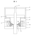
- FIG. 2 is a cross-sectional side view of the operating mechanism section in Example 1 of the electromagnetically operated switchgear of the present invention, showing a state in which the fixed core and the plunger are not in contact with each other.
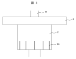
- FIG. 2 is a cross-sectional side view of the operating mechanism section in Example 1 of the electromagnetically operated switchgear of the present invention, showing a state in which the fixed core and the plunger are in contact with each other. It is a side view of the plunger of the operation mechanism part in Example 1 of the electromagnetically operated switchgear of the present invention.
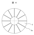
- FIG. 4 is a bottom view of FIG. 3; FIG.
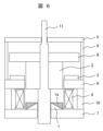
- Example 3 is a cross-sectional side view of the operating mechanism section in Example 2 of the electromagnetically operated switchgear of the present invention, showing a state in which the fixed core and the plunger are not in contact with each other. It is a sectional view seen from the side of the operation mechanism section in Example 3 of the electromagnetically operated switchgear of the present invention, and is a diagram showing a state in which the fixed core and the plunger are not in contact with each other.
- FIG. 1 is a sectional view of the operating mechanism in the electromagnetically operated switchgear according to the first embodiment, viewed from the side, showing a state where the fixed core 1 and the plunger 2 are not in contact with each other
- FIG. 4 is a sectional view of the operating mechanism in the electromagnetically operated switchgear seen from the side, showing a state in which the fixed core 1 and the plunger 2 are in contact
- FIG. 3 is a side view of the plunger 2
- FIG. A bottom view of the plunger 2 is shown.
- the first cylindrical core 9 is held between the first fixed flat plate 5 and the second fixed flat plate 6, the second cylindrical iron core 10 is held between the second fixed flat plate 6 and the third fixed flat plate 7, and the driving rod A plunger 2 and a movable flat plate 8 are connected to the plunger 11.
- the electromagnetic coil 4 is energized, and the coil 4 is surrounded by the plunger 2 ⁇ fixed iron core 1 ⁇ third fixed flat plate 7 ⁇
- a magnetic field is formed in the path of the second cylindrical core 10 ⁇ second fixed flat plate 6 ⁇ plunger 2, and the magnetic field exerts a downward attractive force on the plunger 2, causing the plunger 2 to move along with the drive rod 11 to the fixed core 1 side. , and the plunger 2 is attracted to the fixed iron core 1.
- the current flowing through the coil 4 due to the closing command or the opening command from the control board is a transient current whose magnitude changes over time
- the magnetic material such as the plunger 2 or the fixed iron core 1 in which the magnetic path is formed is a transient current whose magnitude changes over time.
- the magnetic flux inside the components also changes over time.
- the fixed core 1 and the plunger 2 provided with such slits 1a and 2a can prevent the slits 1a and 2a from being formed shallower on the drive rod 11 side even if they collide with the fixed core 1 and the plunger 2 during the closing operation of the switch. Therefore, the reduction in mechanical strength on the drive rod 11 side can be suppressed compared to the outer peripheral side, so that the amount of deformation of the slits 1a and 2a can be suppressed, and the increase in size of the iron core can be suppressed.
- the slit 2a on the plunger 2 side is shallower on the drive rod 11 side (the shaded portion is shorter in the axial direction) and deeper on the outer peripheral side (the shaded portion is longer in the axial direction).
- Embodiment 3 of the electromagnetically operated switchgear of the present invention is shown in FIG.
- a slit 1a is provided only on the contact side of the fixed core 1, extending from the outer circumferential side to the drive rod 11 side (the diagonal line shown in FIG. 6 is the slit 1a). 1a), and the slit 1a on the fixed core 1 side is shallower on the drive rod 11 side (the shaded portion is shorter in the axial direction) and deeper on the outer circumferential side (the shaded portion is longer in the axial direction).
- the slit 1a is shallower on the drive rod 11 side, so the mechanical strength on the drive rod 11 side is reduced. Since the decrease in the slit 1a can be suppressed compared to the outer peripheral side, the amount of deformation of the slit 1a can be suppressed, and the increase in size of the iron core can be suppressed.
- SYMBOLS 1... Fixed iron core, 1a... Slit of fixed iron core, 2... Plunger, 2a... Slit of plunger, 3... Permanent magnet, 4... Coil, 5... First fixed flat plate, 6... Second fixed flat plate, 7... Third 3 fixed flat plate, 8... movable flat plate, 9... first cylindrical core, 10... second cylindrical core, 11... drive rod, 12... slit.
Landscapes
- Physics & Mathematics (AREA)
- Electromagnetism (AREA)
- Engineering & Computer Science (AREA)
- Power Engineering (AREA)
- Driving Mechanisms And Operating Circuits Of Arc-Extinguishing High-Tension Switches (AREA)
- Electromagnets (AREA)
Abstract
本発明は、鉄心の機械的強度の低下を抑制できると共に、鉄心の大形化を抑制できる電磁操作式開閉装置を得るために、コイルと固定鉄心が固定されている固定平板と、前記コイルを貫通するプランジャと、該プランジャが接続され、該プランジャと共に軸方向に移動する駆動ロッドと、前記コイルの上部に配置された永久磁石と、を備え、前記コイルを励磁して前記プランジャを吸引し、前記プランジャと前記固定鉄心との対向面に前記永久磁石が発生する磁束を流して前記プランジャの吸引状態を保持すると共に、前記プランジャの吸引時と逆方向の電流を前記コイルに流して前記プランジャの吸引状態を釈放する電磁操作式開閉装置であって、周方向に所定間隔を持ち、かつ、相対向して配置されている前記プランジャと前記固定鉄心との少なくとも一方の接触部側に、外周側から前記駆動ロッド側に渡ってスリットが設けられ、かつ、前記スリットは、前記駆動ロッド側が浅く、外周側が深く形成されていることを特徴とする。
Description
本発明は電磁操作式開閉装置に係り、特に、電磁操作装置の電磁力を利用して開閉器の接点を入り切りするものに好適な電磁操作式開閉装置に関する。
この種の技術分野における先行技術文献としては、特許文献1に記載された開閉装置を挙げることができる。
この特許文献1には、2つのコイルにパルス電流を供給し、電磁駆動による開閉動作を行う開閉装置において、電磁駆動を高効率、高速に行うと共に、開閉極用の電源の小容量化を実現する開閉装置を提供するために、接離自在な固定電極と可動電極から構成されるスイッチ部と、可動電極に連なる可動軸と可動コイルの間に磁性体を介して固定される可動部と、この可動部に対向して配置された固定コイルの内径側に磁性体を配置した固定部とを備えることにより、各コイル間の発生磁界の増大及び高速な立ち上がりを可能にした開閉装置が記載されている。
上述した特許文献1に記載されている電磁駆動装置(開閉装置)においては、コイルに通電した時に鉄心内部に発生する渦電流を抑制するために設けた複数のスリットは、可動鉄心と固定鉄心の接触部から各々の鉄心の接触部とは反対側まで軸方向に貫通した構成、又は内径側からのスリットと外径側のスリットが繋がっている構成になっている。
この電磁駆動装置は、コイル通電により可動鉄心が高速動作して固定鉄心に衝突するが、スリットは複数設けているため、鉄心の機械的強度が低下してしまい、衝突による衝撃力で各々の鉄心に設けたスリットが変形し、最終的にスリットが潰れてしまう可能性がある。スリットが潰れてスリット溝がなくなると鉄心内部の渦電流を抑制できず、動作速度が低下する。
この対策としては、スリット数を減らして鉄心の機械的強度を確保するか、又はスリットが潰れても溝が接触しないように溝幅を大きくするか、或いは鉄心のサイズを大きくして機械的強度を確保することが考えられるが、いずれの場合も、装置の大形化や動作速度低下となるため、一得一失の関係となる。
本発明上述の点に鑑みなされたもので、その目的とするところは、鉄心の機械的強度の低下を抑制できると共に、鉄心の大形化を抑制できる電磁操作式開閉装置を提供することにある。
本発明の電磁操作式開閉装置は、上記目的を達成するために、コイルと固定鉄心が固定されている固定平板と、前記コイルを貫通するプランジャと、該プランジャが接続され、該プランジャと共に軸方向に移動する駆動ロッドと、前記コイルの上部に配置された永久磁石と、を備え、前記コイルを励磁して前記プランジャを吸引し、前記プランジャと前記固定鉄心との対向面に前記永久磁石が発生する磁束を流して前記プランジャの吸引状態を保持すると共に、前記プランジャの吸引時と逆方向の電流を前記コイルに流して前記プランジャの吸引状態を釈放する電磁操作式開閉装置であって、周方向に所定間隔を持ち、かつ、相対向して配置されている前記プランジャと前記固定鉄心との少なくとも一方の接触部側に、外周側から前記駆動ロッド側に渡ってスリットが設けられ、かつ、前記スリットは、前記駆動ロッド側が浅く、外周側が深く形成されていることを特徴とする。
本発明によれば、鉄心の機械的強度の低下を抑制できると共に、鉄心の大形化を抑制できる電磁操作式開閉装置を得ることができる。
以下、図示した実施例に基づいて本発明の電磁操作式開閉装置を説明する。なお、各実施例において、同一構成部品には同符号を使用する。
図1、図2、図3及び図4に、本発明の電磁操作式開閉装置の実施例1を示す。
図1は、実施例1の電磁操作式開閉装置における操作機構部を側面から見た断面図であり、固定鉄心1とプランジャ2が接触していない状態を示し、図2は、同じく実施例1の電磁操作式開閉装置における操作機構部を側面から見た断面図であり、固定鉄心1とプランジャ2が接触している状態を示し、図3は、プランジャ2の側面図を、図4は、プランジャ2の下面図を示している。
図1及び図2に示すように、本実施例の電磁操作式開閉装置における操作機構部は、固定鉄心1と、プランジャ2と、永久磁石3と、コイル4と、第1の固定平板5と、第2の固定平板6と、第3の固定平板7と、可動平板8と、第1の円筒鉄心9と、第2の円筒鉄心10と、これらの軸上に配置される駆動ロッド11とから概略構成されている。
第1の円筒鉄心9は第1の固定平板5と第2の固定平板6に挟持され、第2の円筒鉄心10は第2の固定平板6と第3の固定平板7に挟持され、駆動ロッド11にはプランジャ2と可動平板8が接続されている。
なお、駆動ロッド11の材質はステンレスなどの非磁性体、永久磁石3はネオジム系磁石など非常に高い磁力を持つ磁石、その他は鉄鋼材などの磁性体で概略構成される。
そして、図示しない操作機構部外部の制御基板などから投入指令が入力されると、電磁石のコイル4が通電され、コイル4の周囲には、プランジャ2→固定鉄心1→第3の固定平板7→第2の円筒鉄心10→第2の固定平板6→プランジャ2の経路で磁界が形成され、その磁界により、プランジャ2には下向きの吸引力が働き、プランジャ2が駆動ロッド11と共に固定鉄心1側に移動し、プランジャ2が固定鉄心1に吸着される。
このとき、永久磁石3によって形成される磁界の向きもコイル4の励磁に伴って発生する磁界の向きと同じになるため、吸引力が高められた状態でプランジャ2が固定鉄心1側に移動する。プランジャ2と固定鉄心1が接触した状態(図2の状態)が、開閉器の投入状態となる。
次に、図示しない外部の制御基板から開極指令が入力され、制御基板からコイル4に開極指令に伴う信号が入力されると、コイル4には投入時とは逆方向の電流が流れ、コイル4の周囲には投入動作時とは逆方向の磁界が形成される。
この場合、コイル4から発生する磁束と永久磁石3から発生する磁束とが互いに打ち消し合い、プランジャ2の軸方向における吸引力は上向きとなり、プランジャ2が固定鉄心1から離間して駆動ロッド11と共に上方向に移動する。このプランジャ2の移動に伴って駆動ロッド11が上方に移動すると、これに連動して開閉器の開極動作が行われ、所定の位置で停止して開極状態となる。
ここで、制御基板からの投入指令や開極指令によりコイル4に通電する電流は、時間と共に大きさが変化する過渡電流であり、プランジャ2や固定鉄心1などの磁路が形成される磁性体の部品内部の磁束も時間と共に変化する。
この時間と共に変化する磁束により、磁性体内部に渦電流が発生し、渦電流による磁束磁界は磁路を妨げる方向に発生する。渦電流で発生した磁界は、コイル通電による磁界を妨げ、動作を遅くする要因になる。
そこで、実施例1では、周方向に所定間隔を持ち、かつ、相対向して配置されているプランジャ2と固定鉄心1との夫々の接触部側に、外周側から駆動ロッド11側に渡ってプランジャ2側のスリット2aと固定鉄心1側のスリット1aが設けられ(図1及び図2に示した斜線部がスリット2a及び1aになる)、しかも、このプランジャ2側のスリット2aと固定鉄心1側のスリット1aは、駆動ロッド11側が浅く(斜線部が軸方向に短く)、外周側が深く(斜線部が軸方向に長く)形成されている。
このようなスリット1a及び2aを設けた固定鉄心1及びプランジャ2は、開閉器の投入動作で固定鉄心1とプランジャ2に衝突しても、スリット1a及び2aは、駆動ロッド11側が浅く形成されているため、駆動ロッド11側の機械的強度の低下が外周側に比べて抑制できるため、スリット1a及び2aの変形量を抑制することができ、鉄心の大形化を抑制できる。
図5に、本発明の電磁操作式開閉装置の実施例2を示す。
図5は、実施例2の電磁操作式開閉装置における操作機構部を側面から見た断面図であり、固定鉄心1とプランジャ2が接触していない状態を示す。実施例1と同様な部分については説明を省略する。
図5に示す本実施例における電磁操作式開閉装置は、プランジャ2の接触部側のみに、外周側から駆動ロッド11側に渡ってスリット2aが設けられ(図5に示した斜線部がスリット2aになる)、しかも、このプランジャ2側のスリット2aは、駆動ロッド11側が浅く(斜線部が軸方向に短く)、外周側が深く(斜線部が軸方向に長く)形成されている。
このようなスリット2aを設けたプランジャ2は、開閉器の投入動作で固定鉄心1に衝突しても、スリット2aは、駆動ロッド11側が浅く形成されているため、駆動ロッド11側の機械的強度の低下が外周側に比べて抑制できるため、スリット2aの変形量を抑制することができ、鉄心の大形化を抑制できる。
図6に、本発明の電磁操作式開閉装置の実施例3を示す。
図6は、実施例3の電磁操作式開閉装置における操作機構部を側面から見た断面図であり、固定鉄心1とプランジャ2が接触していない状態を示す。実施例1と同様な部分については説明を省略する。
図6に示す本実施例における電磁操作式開閉装置は、固定鉄心1の接触部側のみに、外周側から駆動ロッド11側に渡ってスリット1aが設けられ(図6に示した斜線部がスリット1aになる)、しかも、この固定鉄心1側のスリット1aは、駆動ロッド11側が浅く(斜線部が軸方向に短く)、外周側が深く(斜線部が軸方向に長く)形成されている。
このようなスリット1aを設けた固定鉄心1は、開閉器の投入動作でプランジャ2に衝突しても、スリット1aは、駆動ロッド11側が浅く形成されているため、駆動ロッド11側の機械的強度の低下が外周側に比べて抑制できるため、スリット1aの変形量を抑制することができ、鉄心の大形化を抑制できる。
なお、本発明は上記した実施例に限定されるものではなく、様々な変形例が含まれる。
例えば、上記した実施例は本発明を分かりやすく説明するために、具体的に説明したものであり、必ずしも説明した全ての構成を有するものに限定されるものではない。また、ある実施例の構成の一部を、他の実施例の構成の一部に置換することもできる。また、ある実施例の構成に他の実施例の構成を追加することもできる。また、各実施例の構成の一部について、それを削除し、他の構成の一部を追加し、他の構成の一部と置換することもできる。
例えば、上記した実施例は本発明を分かりやすく説明するために、具体的に説明したものであり、必ずしも説明した全ての構成を有するものに限定されるものではない。また、ある実施例の構成の一部を、他の実施例の構成の一部に置換することもできる。また、ある実施例の構成に他の実施例の構成を追加することもできる。また、各実施例の構成の一部について、それを削除し、他の構成の一部を追加し、他の構成の一部と置換することもできる。
1…固定鉄心、1a…固定鉄心のスリット、2…プランジャ、2a…プランジャのスリット、3…永久磁石、4…コイル、5…第1の固定平板、6…第2の固定平板、7…第3の固定平板、8…可動平板、9…第1の円筒鉄心、10…第2の円筒鉄心、11…駆動ロッド、12…スリット。
Claims (4)
- コイルと固定鉄心が固定されている固定平板と、前記コイルを貫通するプランジャと、該プランジャが接続され、該プランジャと共に軸方向に移動する駆動ロッドと、前記コイルの上部に配置された永久磁石と、を備え、
前記コイルを励磁して前記プランジャを吸引し、前記プランジャと前記固定鉄心との対向面に前記永久磁石が発生する磁束を流して前記プランジャの吸引状態を保持すると共に、前記プランジャの吸引時と逆方向の電流を前記コイルに流して前記プランジャの吸引状態を釈放する電磁操作式開閉装置であって、
周方向に所定間隔を持ち、かつ、相対向して配置されている前記プランジャと前記固定鉄心との少なくとも一方の接触部側に、外周側から前記駆動ロッド側に渡ってスリットが設けられ、かつ、前記スリットは、前記駆動ロッド側が浅く、外周側が深く形成されていることを特徴とする電磁操作式開閉装置。 - 請求項1に記載の電磁操作式開閉装置であって、
前記スリットは、前記プランジャと前記固定鉄心の両方の接触部側に設けられていることを特徴とする電磁操作式開閉装置。 - 請求項1に記載の電磁操作式開閉装置であって、
前記スリットは、前記プランジャの接触部側にのみ設けられていることを特徴とする電磁操作式開閉装置。 - 請求項1に記載の電磁操作式開閉装置であって、
前記スリットは、前記固定鉄心の接触部側のみに設けられていることを特徴とする電磁操作式開閉装置。
Applications Claiming Priority (2)
| Application Number | Priority Date | Filing Date | Title |
|---|---|---|---|
| JP2022-097894 | 2022-06-17 | ||
| JP2022097894A JP7711031B2 (ja) | 2022-06-17 | 2022-06-17 | 電磁操作式開閉装置 |
Publications (1)
| Publication Number | Publication Date |
|---|---|
| WO2023243121A1 true WO2023243121A1 (ja) | 2023-12-21 |
Family
ID=89192534
Family Applications (1)
| Application Number | Title | Priority Date | Filing Date |
|---|---|---|---|
| PCT/JP2022/045115 Ceased WO2023243121A1 (ja) | 2022-06-17 | 2022-12-07 | 電磁操作式開閉装置 |
Country Status (2)
| Country | Link |
|---|---|
| JP (1) | JP7711031B2 (ja) |
| WO (1) | WO2023243121A1 (ja) |
Citations (4)
| Publication number | Priority date | Publication date | Assignee | Title |
|---|---|---|---|---|
| JPH11336518A (ja) * | 1998-03-23 | 1999-12-07 | Toyota Motor Corp | 電磁駆動バルブ |
| JP2006322430A (ja) * | 2005-05-20 | 2006-11-30 | Denso Corp | 燃料噴射装置 |
| US20140091243A1 (en) * | 2012-09-28 | 2014-04-03 | Buerkert Werke Gmbh | Sealing system for a solenoid valve and solenoid valve |
| JP2016023748A (ja) * | 2014-07-23 | 2016-02-08 | 日立オートモティブシステムズ株式会社 | 電磁弁 |
-
2022
- 2022-06-17 JP JP2022097894A patent/JP7711031B2/ja active Active
- 2022-12-07 WO PCT/JP2022/045115 patent/WO2023243121A1/ja not_active Ceased
Patent Citations (4)
| Publication number | Priority date | Publication date | Assignee | Title |
|---|---|---|---|---|
| JPH11336518A (ja) * | 1998-03-23 | 1999-12-07 | Toyota Motor Corp | 電磁駆動バルブ |
| JP2006322430A (ja) * | 2005-05-20 | 2006-11-30 | Denso Corp | 燃料噴射装置 |
| US20140091243A1 (en) * | 2012-09-28 | 2014-04-03 | Buerkert Werke Gmbh | Sealing system for a solenoid valve and solenoid valve |
| JP2016023748A (ja) * | 2014-07-23 | 2016-02-08 | 日立オートモティブシステムズ株式会社 | 電磁弁 |
Also Published As
| Publication number | Publication date |
|---|---|
| JP7711031B2 (ja) | 2025-07-22 |
| JP2023184012A (ja) | 2023-12-28 |
Similar Documents
| Publication | Publication Date | Title |
|---|---|---|
| JP6235374B2 (ja) | 開閉器の操作機構 | |
| KR100442676B1 (ko) | 자석가동형 전자액츄에이터 | |
| JP2006108615A (ja) | 電磁アクチュエータ | |
| EP1826784A2 (en) | Electromagnetic actuator | |
| CN105374495A (zh) | 磁性锁闭的磁通转移电子机械致动器 | |
| JP2011513979A (ja) | 電磁動作機構 | |
| JP6301013B2 (ja) | 開閉器 | |
| US20200143970A1 (en) | Electromagnetic actuator and hydraulic pressure adjustment mechanism | |
| CN108780689A (zh) | 螺线管 | |
| JP7711031B2 (ja) | 電磁操作式開閉装置 | |
| JP5627475B2 (ja) | 開閉器の操作機構 | |
| JP2019140207A (ja) | 電磁石装置及び電磁継電器 | |
| JP4580814B2 (ja) | 電磁アクチュエータ | |
| JP7620190B2 (ja) | 双方向アクチュエータ | |
| CN112185721B (zh) | 一种开关装置的驱动组件 | |
| JP4754975B2 (ja) | 有極電磁石 | |
| CN113161102A (zh) | 一种开关电器的电磁铁结构 | |
| JP7161095B2 (ja) | 永久磁石内蔵型ソレノイド | |
| JP6933060B2 (ja) | 電磁継電器 | |
| KR102387712B1 (ko) | 스위치기어 개폐용 구동장치 | |
| JP5543766B2 (ja) | 電磁アクチュエータ | |
| JP2007221049A (ja) | 電磁アクチュエータ | |
| JP2015005692A (ja) | リニアソレノイド | |
| JP2771780B2 (ja) | 電磁石 | |
| JPH073609Y2 (ja) | 電磁装置 |
Legal Events
| Date | Code | Title | Description |
|---|---|---|---|
| 121 | Ep: the epo has been informed by wipo that ep was designated in this application |
Ref document number: 22946936 Country of ref document: EP Kind code of ref document: A1 |
|
| NENP | Non-entry into the national phase |
Ref country code: DE |
|
| 122 | Ep: pct application non-entry in european phase |
Ref document number: 22946936 Country of ref document: EP Kind code of ref document: A1 |