WO2023243074A1 - エレベーターおよび乗りカゴの固定装置 - Google Patents
エレベーターおよび乗りカゴの固定装置 Download PDFInfo
- Publication number
- WO2023243074A1 WO2023243074A1 PCT/JP2022/024286 JP2022024286W WO2023243074A1 WO 2023243074 A1 WO2023243074 A1 WO 2023243074A1 JP 2022024286 W JP2022024286 W JP 2022024286W WO 2023243074 A1 WO2023243074 A1 WO 2023243074A1
- Authority
- WO
- WIPO (PCT)
- Prior art keywords
- car
- elevator
- connector
- fixing device
- movable unit
- Prior art date
- Legal status (The legal status is an assumption and is not a legal conclusion. Google has not performed a legal analysis and makes no representation as to the accuracy of the status listed.)
- Ceased
Links
Images




Classifications
-
- B—PERFORMING OPERATIONS; TRANSPORTING
- B66—HOISTING; LIFTING; HAULING
- B66B—ELEVATORS; ESCALATORS OR MOVING WALKWAYS
- B66B5/00—Applications of checking, fault-correcting, or safety devices in elevators
-
- B—PERFORMING OPERATIONS; TRANSPORTING
- B66—HOISTING; LIFTING; HAULING
- B66B—ELEVATORS; ESCALATORS OR MOVING WALKWAYS
- B66B5/00—Applications of checking, fault-correcting, or safety devices in elevators
- B66B5/02—Applications of checking, fault-correcting, or safety devices in elevators responsive to abnormal operating conditions
- B66B5/16—Braking or catch devices operating between cars, cages, or skips and fixed guide elements or surfaces in hoistway or well
- B66B5/26—Positively-acting devices, e.g. latches, knives
Definitions
- the present invention relates to an elevator and a car fixing device.
- Patent Document 1 As a technology related to a fixing device for an elevator and a car, there is a technology disclosed in Patent Document 1 below.
- This Patent Document 1 describes, ⁇ an engagement body that is attached to a guide rail provided in an elevator hoistway and has an engagement hole; a fixing device having a sliding body that is slidable at a position where it engages with the engagement hole and a position where it releases the engagement, the engagement body being vertically attached to a support fixed to the guide rail ⁇ They are connected so that their positions can be adjusted.''
- the fixing device is installed on the car of the passenger car, but other on-car equipment such as an equipment box and a cooler are also installed on the car. For this reason, the mass of the car becomes heavy, which also increases the mass of the counterweight, which is a factor leading to an increase in cost.
- an object of the present invention is to provide an elevator and a car fixing device that can reduce the weight of the car.
- the present application includes a plurality of means for solving the above problems, and one example thereof is an elevator that includes a car and a fixing device for stopping the movement of the car, the fixing device a movable unit provided at a predetermined height of the running path on which the car runs, and having a fitting member that can freely protrude from an inner wall of the running path to the car;
- the elevator includes a regulating member that fits into the member and regulates movement of the car.
- FIG. 1 is a configuration diagram of an elevator and a car fixing device according to a first embodiment.
- 1 is a perspective view of a car fixing device according to a first embodiment;
- FIG. FIG. 2 is a diagram (part 1) illustrating the configuration of the car fixing device according to the first embodiment.
- FIG. 2 is a diagram (part 2) illustrating the configuration of the car fixing device according to the first embodiment.
- FIG. 3 is a front view (part 1) of the car fixing device according to the second embodiment.
- FIG. 3 is a front view (Part 2) of the car fixing device according to the second embodiment.
- FIG. 7 is a front view (part 1) of a car fixing device according to a third embodiment;
- FIG. 7 is a front view (Part 2) of the car fixing device according to the third embodiment.
- FIG. 1 is a configuration diagram of an elevator 1 and a car fixing device 2 according to the first embodiment, and corresponds to a top view of the elevator 1 viewed from above.
- the elevator 1 has a car 11, a guide rail 12, a counterweight 13, a main rope 14, a hoist 15, and a control panel 16 in a running path 10 provided along a building.
- the elevator 1 includes a fixing device 2 for restricting the movement of the car 11 during inspection of the elevator 1.
- the car 11 is box-shaped, and a car door 11a for getting in and out of the car 11 is provided on a part of the side wall. Further, two guide members 11b in the shape of channel steel are fixed to two outer walls of the car 11 perpendicular to the car door 11a in a state of protruding outward from the car 11 in the horizontal direction. These two guide members 11b are arranged along the traveling direction of the car 11 with the groove-shaped openings facing outward. Note that the two guide members 11b may be fixed to a frame body arranged so as to surround the outer periphery of the car 11.
- a crosshead 11c serving as a frame is arranged at the top of the car 11 and is fixed to the car 11. Furthermore, a part of the fixing device 2, which will be described later, is arranged above the car 11, and an air conditioning equipment 3, an instrument box 4, and the like may also be arranged.
- the instrument box 4 accommodates, for example, an operating section and an electrical wiring board.
- the guide rails 12 are erected on both sides of the car 11 at positions sandwiching the car 11. Each of these guide rails 12 is fixed to the running path 10 via a rail bracket 10b fixed to the inner wall of the running path 10.
- a guide rail 12 is made of, for example, T-shaped steel, and guide members 11b made of groove-shaped steel fixed to the car 11 are slidably engaged with each other to guide the travel of the car 11.
- the counterweight 13 is for balancing the car 11.
- the main rope 14 is passed around a pulley (not shown) fixed to the car 11, and suspends the car 11 and the counterweight 13 like a fishing bottle. Further, the hoist 15 is driven with the intermediate portion of the main rope 14 wound around it, and causes the car 11 suspended from the main rope 14 to travel. Note that the counterweight 13 is also guided in its travel within the travel path 10 by another guide rail 12 a fixed to the inner wall of the travel path 10 .
- Control panel 16 The control panel 16 controls the traveling of the car 11 and the opening and closing of the car door 11a.
- the driving of the car 11 and the car door 11a by the control panel 16 is controlled based on signals from a landing call button and a car call button, which are not shown here, as well as an operation unit and a fixing device 2, which will be described later. Implemented.
- Such a control panel 16 is composed of a computer.
- a computer is hardware used as a so-called computer, and includes a CPU (Central Processing Unit), RAM (Random Access Memory), and non-volatile storage units such as ROM (Read Only Memory) and HDD (Hard Disk Drive). , and even has a network interface.
- the control panel 16 configured by a computer controls the drive of the elevator according to a program stored in the storage section of the computer.
- the location of the control panel 16 is not particularly limited, and may be placed in the running path 10, inside the car 11, on the top of the car 11, or in the machine room if there is a machine room above the running path 10. There may be.
- FIG. 2 is a perspective view of the car fixing device 2 according to the first embodiment.
- FIG. 3 is a diagram (part 1) for explaining the configuration of the car fixing device according to the first embodiment, in which FIG. 3A is a top view and FIG. 3B is a front view, in which the elevator is in normal operation. It shows.
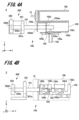
- FIG. 4 is a diagram (part 2) illustrating the configuration of the car fixing device according to the first embodiment, in which FIG. 4A is a top view and FIG. 3B is a front view, and when the movement of the car is restricted. It shows the status of.
- FIGS. 2 to 4 are views of the right-hand fixing device 2 of the two fixing devices 2 shown in FIG. 1.
- the configuration of the fixing device 2 will be explained based on these figures and FIG. 1 explained earlier.
- the fixing device 2 is a mechanical part for regulating the movement of the car 11, and two fixing devices 2 are provided at positions sandwiching the car 11.
- Each of these fixing devices 2 includes a movable unit 100 fixed to the running path 10 and a regulation unit 200 fixed to the car 11.
- the movable unit 100 is fixed at a predetermined height of the running path 10 via a rail bracket 10b (not shown in FIG. 2) fixed to the inner wall of the running path 10.
- the height at which the movable unit 100 is fixed is the height position at which the car 11 is stopped when inspecting the elevator 1, and the height corresponds to the regulation unit 200 provided on the car 11. do.
- the two movable units 100 disposed with the car 11 in between may have a planar symmetrical configuration, or may have the same shape. Further, by fixing the movable unit 100 to the rail bracket 10b for fixing the guide rail 12, there is no need to prepare a member for fixing the movable unit 100, but the present invention is not limited to this. There isn't.
- Such a movable unit 100 has a stopper pin 101, a support casing 102, a handle 103, a short connector 104, a first connector 105a, and a second connector 105b. Furthermore, the movable unit 100 is fixed to the rail bracket 10b in the support casing 102 using a fixing member such as a screw. Each part constituting the movable unit 100 will be explained below.
- the stopper pin 101 is rod-shaped, for example, cylindrical, and can protrude horizontally from the wall of the running path 10 (see FIG. 1) while being supported by a support casing 102, which will be described next. It is.
- This stopper pin 101 has a sufficient length to reach from the wall side of the traveling path 10 relative to the guide rail 12 to the regulation unit 200 described below.
- Such a stopper pin 101 is a fitting member that is fitted with a regulating member 201 of a regulating unit 200 to be described later to regulate the movement of the car 11, and the operation in the fitting operation with the regulating member 201 is can be kept small.
- the support casing 102 is fixed to the wall of the running path 10 via the rail bracket 10b, and allows the stopper pin 101 to freely protrude from the wall of the running path 10 toward the car 11.
- a support case 102 includes two track walls 102a and 102b arranged in parallel. These track walls 102a, 102b have through holes 102aa, 102bb into which the stopper pin 101 is slidably inserted, and regulate the movement direction of the stopper pin 101.
- the track walls 102a and 102b support the stopper pin 101 by inserting the stopper pin 101 into the through holes 102aa and 102bb.
- the support case 102 also has a regulating wall 102c that is perpendicular to the two track walls 102a and 102b.
- This regulation wall 102c is arranged closer to the wall of the traveling path 10 than the two track walls 102a, 102b, and is arranged in parallel with the stopper pin 101 supported by the two track walls 102a, 102b. .
- Such a regulating wall 102c has a first fitting part 102d and a second fitting part 102e. These first fitting portion 102d and second fitting portion 102e are notches provided in the regulating wall 102c, and are perpendicular to the extending direction of the stopper pin 101 supported by the two track walls 102a and 102b.
- the restriction wall 102c is cut out in the direction shown in FIG. In the illustrated example, the first fitting part 102d and the second fitting part 102e are cut out from above downward, but may be cut out from below upward.
- the handle 103 extends perpendicularly to the axial direction of the stopper pin 101 from the side peripheral wall of the stopper pin 101, and rotates the stopper pin 101 around the axis and moves the stopper pin 101 in the axial direction. This is the operation section for controlling the
- the handle 103 has a protruding length and diameter that allows it to be fitted into each of the first fitting part 102d and the second fitting part 102e by rotation and movement of the stopper pin 101.
- the handle 103 has a shape that facilitates rotation and movement of the stopper pin 101 by an operator.
- the handle 103 When the handle 103 is fitted into the first fitting portion 102d (see FIGS. 2, 3A, and 3B), the handle 103 has the distal end of the stopper pin 101 inside the support casing 102 and on the guide rail 12 side. accommodate. Further, in this state, the stopper pin 101 is held in a state where it is supported by the two track walls 102a and 102b. Furthermore, when the handle 103 is fitted into the second fitting portion 102e (see FIGS. 4A and 4B), the distal end side of the stopper pin 101 protrudes from the support casing 102 and the guide rail 12, and the handle 103 allows the stopper pin 101 to protrude from the support casing 102 and the guide rail 12. Let it reach 200. Further, in this state, the stopper pin 101 is held in a state where it is supported by the two track walls 102a and 102b.
- the short connector 104 is for connecting one of the two connectors, a first connector 105a and a second connector 105b, which will be described next, in a conductive state, and is inserted into either of these, for example.
- a short connector 104 is attached to the handle 103 and moves together with the handle 103 between the first fitting part 102d and the second fitting part 102e.
- the first connector 105a and the second connector 105b enter a electrically connected state by inserting the short connector 104, and transmit a signal indicating the connected state to the control panel 16.
- the short connector 104 fixed to the handle 103 can be freely inserted into the first connector 105a when the handle 103 is fitted into the first fitting part 102d. Since the first connector 105a is in the connected state, the control panel 16 that has received the signal from the first connector 105a permits normal operation of the elevator 1. Further, the control panel 16 determines permission/disapproval of each operation by an operation section installed in the equipment box 4 or on the top of the car 11, for example, by receiving a signal from the first connector 105a.
- the short connector 104 fixed to the handle 103 can be freely inserted into the second connector 105b when the handle 103 is fitted into the second fitting part 102e. Since the second connector 105b is in the connected state, the control panel 16 that has received the signal from the second connector 105b disables normal operation of the elevator 1. In addition, the control panel 16 determines whether to permit or disallow each operation by the operating section installed in the instrument box 4 or on the upper part of the car 11 by receiving a signal from the second connector 105b.
- the support casing 102 may be provided with a removable cover member to prevent unintended operation of the handle 103 and the short connector 104.
- the regulation unit 200 is fixed to both sides of the car 11 via, for example, a crosshead 11c (shown only in FIG. 1).
- a regulation unit 200 includes a regulation member 201 and a holding member 202. These are as follows.
- the regulating member 201 is a plate-shaped member, and has a through hole 201a into which the stopper pin 101 of the movable unit 100 is inserted and fitted.
- the regulating member 201 regulates the movement of the car 11 by fitting the stopper pin 101 into the through hole 201a.
- the holding member 202 is a plate-like member fixed at a position where the tip of the stopper pin 101 comes into contact, and has a recess 202a that accommodates the tip of the stopper pin 101.
- Such a holding member 202 also serves as a regulating member that regulates movement of the car 11 by inserting and fitting the stopper pin 101 into the recess 202a.
- the regulation unit 200 includes at least one of a regulation member 201 and a holding member 202 serving as a regulation member.
- a switch 202b that is turned on when the tip of the stopper pin 101 comes into contact with the bottom surface of the recess 202a may be provided.
- a switch 202b is arranged so that the tip of the stopper pin 101 comes into contact with the stopper pin 101 when the stopper pin 101 is moved to a position where the handle 103 is fitted into the second fitting part 102e.
- the switch 202b is wired inside the equipment box 4 on the car 11, and the signal generated when the switch 202b is turned on is transmitted from inside the equipment box 4 to the control panel 16. Therefore, the wiring route is short and easy.
- the control panel 16 that receives the signal indicating that the switch 202b is in the on state disables normal operation of the elevator 1.
- the control panel 16 determines permission/disapproval of each operation by the operation section in the instrument box 4 by receiving a signal from the switch 202b. Therefore, when the regulation unit 200 is provided with the switch 202b, the short connect 104, the first connector 105a, and the second connector 105b provided in the movable unit 100 may be provided as necessary.
- the movable unit 100 for regulating the movement of the car 11 is fixed on the traveling path 10 side, and only the restriction member 201 and the holding member 202, which are plate-like members, are attached to the car 11. It has a fixed configuration. This makes it possible to reduce the mass of the carriage 11 and further reduce the mass of the counterweight 13 compared to the case where the movable unit 100 is fixed on the carriage 11, thereby reducing the product cost of the elevator 1. can be reduced. Furthermore, since the space occupied by the movable unit 100 when the movable unit 100 is fixed on the car 11 becomes vacant, it is also possible to secure a work space.
- the elevator of the second embodiment differs from the elevator of the first embodiment described using FIG. 1 only in the configuration of the fixing device. For this reason, only the fixing device of the second embodiment will be described below.
- FIG. 5 is a front view (part 1) of the car fixing device 2' according to the second embodiment, showing a state in which the elevator is in normal operation.
- FIG. 6 is a front view (part 2) of the car fixing device 2' according to the second embodiment, showing a state when movement of the car is restricted.
- the car fixing device 2' shown in these figures differs from the car fixing device described in the first embodiment in that a switch part 203' is provided on the regulation unit 200' side instead of the holding member. It's in the configuration.
- the structure of the regulating member 201 in the movable unit 100 and the regulating unit 200' is assumed to be the same as that of the first embodiment.
- the switch section 203' is a roller type switch provided at a position where the tip of the stopper pin 101 comes into contact, and includes a switch housing 203a', a switch 203b', and a roller 203c'.
- the switch housing 203a' holds the switch 203b' and the roller 203c', and is fixed to the upper part of the car 11.
- the switch 203b' is turned on by the roller 203c'.
- the roller 203c' is pushed by the tip of the stopper pin 101 in the process of moving the stopper pin 101 to a position where the handle 103 is fitted into the second fitting part 102e while the roller 203c' is fixed to the upper part of the car 11. and turn on the switch 203b' (see FIG. 6).
- the switch 203b' is wired inside the appliance box 4 on the car 11, and the signal generated when the switch 203b' is turned on is transmitted from inside the appliance box 4 to the control panel 16. Therefore, the wiring route is short and easy.
- the control panel 16 that receives the signal indicating that the switch 203b' is in the on state disables normal operation of the elevator 1.
- the control panel 16 determines permission/disapproval of each operation by the operation section in the instrument box 4 by receiving a signal from the switch 203b'. Therefore, when the regulation unit 200' is provided with the switch 203b', the short connect 104, the first connector 105a, and the second connector 105b provided in the movable unit 100 may be provided as necessary.
- the movable unit 100 for regulating the movement of the car 11 is fixed on the traveling path 10 side, and the car 11 is provided with a regulating member 201 that is a plate-like member and a switch. Only the portion 203' is fixed.
- the product cost of the elevator 1 can be reduced.
- the space occupied by the movable unit 100 when the movable unit 100 is fixed on the car 11 becomes vacant, it is also possible to secure a work space.
- the elevator of the third embodiment differs from the elevator of the first embodiment described using FIG. 1 only in the configuration of the fixing device. Therefore, only the fixing device of the third embodiment will be described below.
- FIG. 7 is a front view (part 1) of the car fixing device 2'' according to the third embodiment, showing a state in which the elevator is in normal operation.
- FIG. 2 is a front view (part 2) of the car fixing device 2'', showing a state when movement of the car is restricted.
- the car-car fixing device 2'' shown in these figures differs from the car-car fixing device described in the first embodiment in the configurations of the movable unit 100'' and the regulation unit 200''. The configurations of the movable unit 100'' and the regulation unit 200'' will be described with reference to FIG. 1 as well as FIG. 8.
- the movable unit 100'' is fixed at a predetermined height of the running path 10 via a rail bracket 10b (not shown in FIG. 2) fixed to the inner wall of the running path 10.
- the height at which is fixed is the height position at which the car 11 is stopped when inspecting the elevator 1, and corresponds to the regulation unit 200'' provided on the car 11.
- the rail bracket 10b may be one for fixing the guide rail 12 to the running path 10, but may be another one.
- Such a movable unit 100'' has a shaft member 106'', a fitting member 107'', a short connector 104, a first connector 105a, and a second connector 105b. Each part constituting the movable unit 100'' will be described below. .
- the shaft member 106'' is a cylindrical rotating shaft, and is fixed to the wall of the traveling path 10 via the rail bracket 10b with its axis oriented in the traveling direction of the car.
- the fitting member 107'' is a member that extends from the shaft member 106'' in a direction perpendicular to the shaft member 106''.
- the fitting member 107'' moves the tip position by rotation of the shaft member 106''. In other words, the tip of the fitting member 107'' goes from being closer to the wall of the running path 10 than the guide rail 12 (see FIG. 7) to reaching the regulation unit 200'' to be described later (see FIG. 8). (Reference) Have sufficient length.
- this fitting member 107'' is fitted to a regulating member 206'' of a regulating unit 200'', which will be described next.
- 206'' and the carriage 11 to which it is fixed are restricted.
- the distal end of the fitting member 107'' has a shape that holds the regulating member 206'' while pressing the regulating member 206'' from above, for example (see FIG. 8).
- fitting member 107'' is provided with a bolt hole 107a'' as necessary in a portion that holds the regulating member 206''.
- the short connector 104 is similar to that described in the first embodiment, and is used to bring either one of the two connectors, the first connector 105a and the second connector 105b, into a conductive state. For example, it can be inserted into either of these.
- Such a short connector 104 is attached to a fitting member 107'' and moves between positions sandwiching the shaft member 106'' as the fitting member 107'' rotates.
- first connector 105a and second connector 105b- The first connector 105a and the second connector 105b are the same as those described in the first embodiment, and when the short connector 104 is inserted, they become connected and conductive, and send a signal indicating the connection state to the control panel 16. do.
- the first connector 105a is fixed to the rail bracket 10b closer to the wall of the traveling path 10 than the shaft member 106''.
- the first connector 105a is connected to the fitting member 107 by rotation of the shaft member 106''.
- the tip of the short connector 104 is located on the wall side of the running path 10, the short connector 104 can be inserted freely.
- a signal from the first connector 105a is received.
- the control panel 16 allows normal operation of the elevator 1. Furthermore, the control panel 16 allows each operation by an operation section installed in the equipment box 4 or on the top of the car 11, for example, by receiving a signal from the first connector 105a. Determine permission/disapproval.
- the second connector 105b is fixed to the rail bracket 10b on the side closer to the car 11 than the shaft member 106''.
- the second connector 105b is fixed to the rail bracket 10b on the side closer to the car 11 than the shaft member 106''.
- the short connector 104 can be inserted freely.
- the control panel 16 that has received the signal from the second connector 105b is connected to the elevator 1. Normal operation is disabled.
- the control panel 16 also determines permission/disapproval of each operation by the operation unit installed inside the equipment box 4 or on the top of the car 11 based on the signal received from the second connector 105b. .
- the regulation unit 200'' is fixed to the car 11 via, for example, a crosshead 11c.
- Such a regulation unit 200'' includes a regulation member 206''.
- the regulating member 206'' prevents the movement of the regulating member 206'' and the car 11 with respect to the wall of the traveling path 10 to which the fitting member 107'' is fixed. (See FIG. 8).
- the regulating member 206'' is a plate material that fits into the fitting member 107'' from below, and is pressed down from above by the fitting member 107''. This restricts the upward movement of the car 11.
- Such a regulating member 206'' is provided with a bolt hole 206a'' as necessary in a portion that is held between the fitting member 107'' when the regulating member 206'' is fitted with the fitting member 107''.
- the bolt 108'' is inserted into the bolt hole 107a'' of the fitting member 107'' and the bolt hole 206a'' of the regulating member 206''. It can be tightened with a nut 109''.
- the above-mentioned regulating member 206'' has a switch (which is turned on when the fitting member 107'' comes into contact with the part that contacts the fitting member 107'' in the fitted state with the fitting member 107''). (not shown) may also be provided.
- the switch provided on the regulating member 206'' is wired inside the appliance box 4 on the car 11, and the signal generated when the switch is turned on is transmitted from inside the appliance box 4 to the control panel 16. , the wiring route is short and easy.
- the short connector 104, the first connector 105a, and the second connector 105b provided in the movable unit 100 may be provided as necessary.
- the movable unit 100'' for regulating the movement of the car 11 is fixed on the traveling path 10 side, and the car 11 only has a regulating member 206'' which is a plate-like member. It has a fixed configuration.
- the product cost of the elevator 1 can be reduced.Furthermore, when the movable unit 100'' is fixed on the car 11, the space occupied by the movable unit 100'' becomes vacant, so a work space can be secured. It is also possible to do so.
- the present invention is not limited to the above-described embodiments and modifications, and includes various modifications.
- the above-described embodiments have been described in detail to explain the present invention in an easy-to-understand manner, and the present invention is not necessarily limited to having all the configurations described.
Landscapes
- Engineering & Computer Science (AREA)
- Mechanical Engineering (AREA)
- Cage And Drive Apparatuses For Elevators (AREA)
Priority Applications (2)
| Application Number | Priority Date | Filing Date | Title |
|---|---|---|---|
| JP2024528056A JPWO2023243074A1 (https=) | 2022-06-17 | 2022-06-17 | |
| PCT/JP2022/024286 WO2023243074A1 (ja) | 2022-06-17 | 2022-06-17 | エレベーターおよび乗りカゴの固定装置 |
Applications Claiming Priority (1)
| Application Number | Priority Date | Filing Date | Title |
|---|---|---|---|
| PCT/JP2022/024286 WO2023243074A1 (ja) | 2022-06-17 | 2022-06-17 | エレベーターおよび乗りカゴの固定装置 |
Publications (1)
| Publication Number | Publication Date |
|---|---|
| WO2023243074A1 true WO2023243074A1 (ja) | 2023-12-21 |
Family
ID=89192689
Family Applications (1)
| Application Number | Title | Priority Date | Filing Date |
|---|---|---|---|
| PCT/JP2022/024286 Ceased WO2023243074A1 (ja) | 2022-06-17 | 2022-06-17 | エレベーターおよび乗りカゴの固定装置 |
Country Status (2)
| Country | Link |
|---|---|
| JP (1) | JPWO2023243074A1 (https=) |
| WO (1) | WO2023243074A1 (https=) |
Citations (5)
| Publication number | Priority date | Publication date | Assignee | Title |
|---|---|---|---|---|
| JPS54135462U (https=) * | 1978-03-13 | 1979-09-20 | ||
| JP2000203774A (ja) * | 1998-11-12 | 2000-07-25 | Toshiba Corp | エレベ―タ籠の停止ロック装置 |
| JP2001199647A (ja) * | 2000-01-19 | 2001-07-24 | Hitachi Ltd | エレベーター装置 |
| JP2007084327A (ja) * | 2005-09-26 | 2007-04-05 | Toshiba Elevator Co Ltd | エレベータの制御盤支持装置 |
| CN108975121A (zh) * | 2018-08-30 | 2018-12-11 | 住友富士电梯有限公司 | 防坠电梯及其控制方法 |
-
2022
- 2022-06-17 JP JP2024528056A patent/JPWO2023243074A1/ja active Pending
- 2022-06-17 WO PCT/JP2022/024286 patent/WO2023243074A1/ja not_active Ceased
Patent Citations (5)
| Publication number | Priority date | Publication date | Assignee | Title |
|---|---|---|---|---|
| JPS54135462U (https=) * | 1978-03-13 | 1979-09-20 | ||
| JP2000203774A (ja) * | 1998-11-12 | 2000-07-25 | Toshiba Corp | エレベ―タ籠の停止ロック装置 |
| JP2001199647A (ja) * | 2000-01-19 | 2001-07-24 | Hitachi Ltd | エレベーター装置 |
| JP2007084327A (ja) * | 2005-09-26 | 2007-04-05 | Toshiba Elevator Co Ltd | エレベータの制御盤支持装置 |
| CN108975121A (zh) * | 2018-08-30 | 2018-12-11 | 住友富士电梯有限公司 | 防坠电梯及其控制方法 |
Also Published As
| Publication number | Publication date |
|---|---|
| JPWO2023243074A1 (https=) | 2023-12-21 |
Similar Documents
| Publication | Publication Date | Title |
|---|---|---|
| US7293631B2 (en) | Machine room-less elevator | |
| US7117977B2 (en) | Elevator apparatus including car with suspending pulley devices on opposite sides of the car | |
| JP5330666B2 (ja) | 昇降路内に2つのエレベータケージを互いに上下に配置して備えるエレベータ | |
| US7562745B2 (en) | Elevator with an operation space in a center of a machine room | |
| KR20170136562A (ko) | 승강기 통로에 대한 액세스를 위한 승강기 승강칸 벽 | |
| KR100567364B1 (ko) | 엘리베이터 장치 | |
| WO2023243074A1 (ja) | エレベーターおよび乗りカゴの固定装置 | |
| JP6270923B2 (ja) | 据付装置 | |
| JPWO2003020628A1 (ja) | エレベータ装置 | |
| JP5679602B1 (ja) | 階間調整機能付きエレベータ | |
| JPWO2004041702A1 (ja) | エレベータ装置 | |
| KR100685505B1 (ko) | 엘리베이터 장치 | |
| JP2003312960A (ja) | エレベータ装置 | |
| EP1556304B1 (en) | Elevator | |
| JP7222126B1 (ja) | 回転式ロープブレーキ装置 | |
| JPH08333066A (ja) | エレベーター用ロープ破断検出装置 | |
| JPWO2005105652A1 (ja) | エレベータ装置 | |
| US7299896B1 (en) | Elevator system having drive motor located adjacent to hoistway door | |
| WO2023218620A1 (ja) | エレベーターおよびエレベーターの点検方法 | |
| CN101522555A (zh) | 无机房的电梯装置 | |
| WO2025022596A1 (ja) | 乗りかご及びエレベーター | |
| JP2730414B2 (ja) | エレベータかごの制振装置 | |
| EP1500620A1 (en) | Elevator | |
| JP5902135B2 (ja) | 階間調整機能付きエレベータ | |
| EP1571113A1 (en) | Elevator equipment |
Legal Events
| Date | Code | Title | Description |
|---|---|---|---|
| 121 | Ep: the epo has been informed by wipo that ep was designated in this application |
Ref document number: 22946890 Country of ref document: EP Kind code of ref document: A1 |
|
| WWE | Wipo information: entry into national phase |
Ref document number: 2024528056 Country of ref document: JP |
|
| NENP | Non-entry into the national phase |
Ref country code: DE |
|
| 122 | Ep: pct application non-entry in european phase |
Ref document number: 22946890 Country of ref document: EP Kind code of ref document: A1 |