WO2023238584A1 - 被覆活物質、電極材料、電池および電池の製造方法 - Google Patents
被覆活物質、電極材料、電池および電池の製造方法 Download PDFInfo
- Publication number
- WO2023238584A1 WO2023238584A1 PCT/JP2023/017476 JP2023017476W WO2023238584A1 WO 2023238584 A1 WO2023238584 A1 WO 2023238584A1 JP 2023017476 W JP2023017476 W JP 2023017476W WO 2023238584 A1 WO2023238584 A1 WO 2023238584A1
- Authority
- WO
- WIPO (PCT)
- Prior art keywords
- active material
- solid electrolyte
- coated active
- coating layer
- battery
- Prior art date
- Legal status (The legal status is an assumption and is not a legal conclusion. Google has not performed a legal analysis and makes no representation as to the accuracy of the status listed.)
- Ceased
Links
Images



Classifications
-
- H—ELECTRICITY
- H01—ELECTRIC ELEMENTS
- H01M—PROCESSES OR MEANS, e.g. BATTERIES, FOR THE DIRECT CONVERSION OF CHEMICAL ENERGY INTO ELECTRICAL ENERGY
- H01M10/00—Secondary cells; Manufacture thereof
- H01M10/05—Accumulators with non-aqueous electrolyte
- H01M10/056—Accumulators with non-aqueous electrolyte characterised by the materials used as electrolytes, e.g. mixed inorganic/organic electrolytes
- H01M10/0561—Accumulators with non-aqueous electrolyte characterised by the materials used as electrolytes, e.g. mixed inorganic/organic electrolytes the electrolyte being constituted of inorganic materials only
- H01M10/0562—Solid materials
-
- H—ELECTRICITY
- H01—ELECTRIC ELEMENTS
- H01M—PROCESSES OR MEANS, e.g. BATTERIES, FOR THE DIRECT CONVERSION OF CHEMICAL ENERGY INTO ELECTRICAL ENERGY
- H01M10/00—Secondary cells; Manufacture thereof
- H01M10/05—Accumulators with non-aqueous electrolyte
- H01M10/052—Li-accumulators
-
- H—ELECTRICITY
- H01—ELECTRIC ELEMENTS
- H01M—PROCESSES OR MEANS, e.g. BATTERIES, FOR THE DIRECT CONVERSION OF CHEMICAL ENERGY INTO ELECTRICAL ENERGY
- H01M10/00—Secondary cells; Manufacture thereof
- H01M10/05—Accumulators with non-aqueous electrolyte
- H01M10/052—Li-accumulators
- H01M10/0525—Rocking-chair batteries, i.e. batteries with lithium insertion or intercalation in both electrodes; Lithium-ion batteries
-
- H—ELECTRICITY
- H01—ELECTRIC ELEMENTS
- H01M—PROCESSES OR MEANS, e.g. BATTERIES, FOR THE DIRECT CONVERSION OF CHEMICAL ENERGY INTO ELECTRICAL ENERGY
- H01M4/00—Electrodes
- H01M4/02—Electrodes composed of, or comprising, active material
- H01M4/04—Processes of manufacture in general
-
- H—ELECTRICITY
- H01—ELECTRIC ELEMENTS
- H01M—PROCESSES OR MEANS, e.g. BATTERIES, FOR THE DIRECT CONVERSION OF CHEMICAL ENERGY INTO ELECTRICAL ENERGY
- H01M4/00—Electrodes
- H01M4/02—Electrodes composed of, or comprising, active material
- H01M4/13—Electrodes for accumulators with non-aqueous electrolyte, e.g. for lithium-accumulators; Processes of manufacture thereof
- H01M4/131—Electrodes based on mixed oxides or hydroxides, or on mixtures of oxides or hydroxides, e.g. LiCoOx
-
- H—ELECTRICITY
- H01—ELECTRIC ELEMENTS
- H01M—PROCESSES OR MEANS, e.g. BATTERIES, FOR THE DIRECT CONVERSION OF CHEMICAL ENERGY INTO ELECTRICAL ENERGY
- H01M4/00—Electrodes
- H01M4/02—Electrodes composed of, or comprising, active material
- H01M4/13—Electrodes for accumulators with non-aqueous electrolyte, e.g. for lithium-accumulators; Processes of manufacture thereof
- H01M4/139—Processes of manufacture
- H01M4/1391—Processes of manufacture of electrodes based on mixed oxides or hydroxides, or on mixtures of oxides or hydroxides, e.g. LiCoOx
-
- H—ELECTRICITY
- H01—ELECTRIC ELEMENTS
- H01M—PROCESSES OR MEANS, e.g. BATTERIES, FOR THE DIRECT CONVERSION OF CHEMICAL ENERGY INTO ELECTRICAL ENERGY
- H01M4/00—Electrodes
- H01M4/02—Electrodes composed of, or comprising, active material
- H01M4/36—Selection of substances as active materials, active masses, active liquids
- H01M4/362—Composites
- H01M4/366—Composites as layered products
-
- H—ELECTRICITY
- H01—ELECTRIC ELEMENTS
- H01M—PROCESSES OR MEANS, e.g. BATTERIES, FOR THE DIRECT CONVERSION OF CHEMICAL ENERGY INTO ELECTRICAL ENERGY
- H01M4/00—Electrodes
- H01M4/02—Electrodes composed of, or comprising, active material
- H01M4/36—Selection of substances as active materials, active masses, active liquids
- H01M4/48—Selection of substances as active materials, active masses, active liquids of inorganic oxides or hydroxides
- H01M4/52—Selection of substances as active materials, active masses, active liquids of inorganic oxides or hydroxides of nickel, cobalt or iron
- H01M4/525—Selection of substances as active materials, active masses, active liquids of inorganic oxides or hydroxides of nickel, cobalt or iron of mixed oxides or hydroxides containing iron, cobalt or nickel for inserting or intercalating light metals, e.g. LiNiO2, LiCoO2 or LiCoOxFy
-
- H—ELECTRICITY
- H01—ELECTRIC ELEMENTS
- H01M—PROCESSES OR MEANS, e.g. BATTERIES, FOR THE DIRECT CONVERSION OF CHEMICAL ENERGY INTO ELECTRICAL ENERGY
- H01M4/00—Electrodes
- H01M4/02—Electrodes composed of, or comprising, active material
- H01M2004/021—Physical characteristics, e.g. porosity, surface area
-
- H—ELECTRICITY
- H01—ELECTRIC ELEMENTS
- H01M—PROCESSES OR MEANS, e.g. BATTERIES, FOR THE DIRECT CONVERSION OF CHEMICAL ENERGY INTO ELECTRICAL ENERGY
- H01M4/00—Electrodes
- H01M4/02—Electrodes composed of, or comprising, active material
- H01M2004/026—Electrodes composed of, or comprising, active material characterised by the polarity
- H01M2004/028—Positive electrodes
-
- H—ELECTRICITY
- H01—ELECTRIC ELEMENTS
- H01M—PROCESSES OR MEANS, e.g. BATTERIES, FOR THE DIRECT CONVERSION OF CHEMICAL ENERGY INTO ELECTRICAL ENERGY
- H01M2300/00—Electrolytes
- H01M2300/0017—Non-aqueous electrolytes
- H01M2300/0065—Solid electrolytes
- H01M2300/0068—Solid electrolytes inorganic
-
- H—ELECTRICITY
- H01—ELECTRIC ELEMENTS
- H01M—PROCESSES OR MEANS, e.g. BATTERIES, FOR THE DIRECT CONVERSION OF CHEMICAL ENERGY INTO ELECTRICAL ENERGY
- H01M2300/00—Electrolytes
- H01M2300/0017—Non-aqueous electrolytes
- H01M2300/0065—Solid electrolytes
- H01M2300/0068—Solid electrolytes inorganic
- H01M2300/008—Halides
-
- Y—GENERAL TAGGING OF NEW TECHNOLOGICAL DEVELOPMENTS; GENERAL TAGGING OF CROSS-SECTIONAL TECHNOLOGIES SPANNING OVER SEVERAL SECTIONS OF THE IPC; TECHNICAL SUBJECTS COVERED BY FORMER USPC CROSS-REFERENCE ART COLLECTIONS [XRACs] AND DIGESTS
- Y02—TECHNOLOGIES OR APPLICATIONS FOR MITIGATION OR ADAPTATION AGAINST CLIMATE CHANGE
- Y02E—REDUCTION OF GREENHOUSE GAS [GHG] EMISSIONS, RELATED TO ENERGY GENERATION, TRANSMISSION OR DISTRIBUTION
- Y02E60/00—Enabling technologies; Technologies with a potential or indirect contribution to GHG emissions mitigation
- Y02E60/10—Energy storage using batteries
Definitions
- the present disclosure relates to a coated active material, an electrode material, a battery, and a method for manufacturing the battery.
- Non-Patent Document 1 discloses a battery using sulfide as a solid electrolyte.
- an active material a coating layer containing a first solid electrolyte and covering at least a portion of the surface of the active material;
- a coated active material comprising: The first solid electrolyte contains fluoride, The mass of the coating layer that peels off from the active material when the coated active material is dispersed in an organic dispersion medium is less than 42% of the total mass of the coating layer.
- a coated active material is provided.
- FIG. 1 is a cross-sectional view showing a schematic configuration of a coated active material in Embodiment 1.
- FIG. 2 is a cross-sectional view showing a schematic configuration of a coated active material in a modified example.
- FIG. 3 is a cross-sectional view showing a schematic structure of an electrode material in the second embodiment.
- FIG. 4 is a sectional view showing a schematic configuration of a battery in Embodiment 3.
- FIG. 5 is a flowchart showing a method for manufacturing a battery.
- FIG. 6 is a graph showing the relationship between DC resistance and peeling rate.
- FIG. 7 is a graph showing the relationship between the increase rate of resistance and the peeling rate.
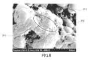
- FIG. 8 is a SEM image of the coated active material of Example 3.
- the solid electrolyte may be oxidized and decomposed during battery charging. This tendency is remarkable when the solid electrolyte has poor oxidation resistance, such as a sulfide solid electrolyte.
- the surface of the active material is coated with a coating material having excellent oxidation resistance, such as a halide solid electrolyte.
- the present inventors noticed that even if the composition of the coating material is the same, differences occur in battery characteristics, especially resistance. Furthermore, the present inventors discovered that there is a correlation between the amount of peeling of the coating material from the active material and the characteristics of the battery, and came up with the present disclosure.
- the coated active material according to the first aspect of the present disclosure is: an active material; a coating layer containing a first solid electrolyte and covering at least a portion of the surface of the active material;
- a coated active material comprising: The first solid electrolyte contains fluoride, The mass of the coating layer that peels off from the active material when the coated active material is dispersed in an organic dispersion medium is less than 42% of the total mass of the coating layer.
- the absorbance at a wavelength of 400 nm measured for a supernatant liquid obtained by dispersing and precipitating the coated active material in the organic dispersion medium is It may be less than 0.63. According to such a configuration, the characteristics of the battery can be further improved.
- the coating layer may have a particle-like structure including a plurality of particles with a diameter of 500 nm or less.
- the coating layer has a fine particle-like structure, deformation of the coating layer is promoted during production of the electrode plate, so that a good interface can be formed between the coating active material and other materials. As a result, the resistance of the battery can be further reduced.
- the coating layer may have a plurality of pores with a diameter of 50 nm or less.
- the coating layer has fine pores, deformation of the coating layer is promoted during production of the electrode plate, so that a good interface can be formed between the coating active material and other materials. As a result, the resistance of the battery can be further reduced.
- the coated active material according to any one of the first to fourth aspects even if the mass of the coating layer is 4.5% or less of the mass of the coated active material. good. According to such a configuration, the resistance of the battery can be further reduced.
- the active material may be a positive electrode active material. If the technology of the present disclosure is applied to a positive electrode active material, it becomes possible to use a solid electrolyte that has poor oxidation resistance but high ionic conductivity for the positive electrode.
- the first solid electrolyte may be represented by the following compositional formula (2).
- x satisfies 0 ⁇ x ⁇ 1.2
- n is the weighted average valence of the elements contained in M
- M is a metal or metalloid
- X contains fluorine or contains fluorine and chlorine.
- M may be at least one selected from the group consisting of Ca, Mg, Al, Y, Ti, and Zr. According to such a configuration, the ionic conductivity of the coating layer can be improved, and the resistance of the battery can be effectively reduced.
- M may be at least one selected from the group consisting of Al, Ti, and Zr. According to such a configuration, the ionic conductivity of the coating layer can be improved, and the resistance of the battery can be effectively reduced.
- M may be at least one selected from the group consisting of Ti and Al.
- M contains Al and/or Ti, the halide solid electrolyte exhibits high ionic conductivity.
- the ratio of the amount of Li to the total amount of M may be 1.7 or more and 4.2 or less. According to such a configuration, the ionic conductivity of the first solid electrolyte can be further increased.
- the electrode material according to the twelfth aspect of the present disclosure is A coated active material according to any one of the first to eleventh aspects, a second solid electrolyte; Equipped with
- the second solid electrolyte may include a sulfide solid electrolyte.
- the battery according to the fourteenth aspect of the present disclosure includes: A positive electrode including the electrode material of the twelfth or thirteenth aspect is provided.
- the battery according to the fifteenth aspect of the present disclosure includes: A positive electrode comprising the electrode material of the twelfth or thirteenth aspect, a negative electrode; an electrolyte layer disposed between the positive electrode and the negative electrode; Equipped with
- the electrode material of the present disclosure is suitable for suppressing increases in battery resistance due to durability tests.
- the method for manufacturing a battery according to the sixteenth aspect of the present disclosure includes: preparing an electrode material by mixing the coated active material of any one of the first to eleventh aspects and a second solid electrolyte; forming an electrode using the electrode material; including.
- the coating layer does not easily peel off from the active material, the active material is sufficiently protected by the coating layer even in the prepared positive electrode material.
- the electrode material may be a slurry containing the coated active material, the second solid electrolyte, and a solvent. According to the present disclosure, desired effects can be obtained even when electrodes are manufactured by a so-called wet method.
- FIG. 1 is a cross-sectional view showing a schematic configuration of a coated active material 130 in the first embodiment.
- Coated active material 130 includes active material 110 and coating layer 111.
- the shape of the active material 110 is, for example, particulate.
- the coating layer 111 covers at least a portion of the surface of the active material 110.
- the covering layer 111 is a layer containing the first solid electrolyte.
- a coating layer 111 is provided on the surface of the active material 110.
- the first solid electrolyte contains fluoride.
- the first solid electrolyte may be a solid electrolyte containing halogen.
- Solid electrolytes containing halogens are often also referred to as halide solid electrolytes.
- Halide solid electrolytes have excellent oxidation resistance.
- a halide solid electrolyte containing fluorine (F) has excellent oxidation resistance due to its high electronegativity. Therefore, by covering the active material 110 with the first solid electrolyte, oxidation of other solid electrolytes in contact with the active material 110 can be suppressed. Thereby, it is possible to suppress an increase in the resistance of the battery due to the durability test.
- the mass of the coating layer 111 that peels off from the active material 110 when the coated active material 130 is dispersed in an organic dispersion medium is less than 42% of the total mass of the coating layer 111.
- the battery manufacturing process may include a step of dispersing and mixing a coated active material, solid electrolyte, and auxiliary materials (such as a conductive aid) in an organic dispersion medium. If the peeling rate is high, the coating layer will peel off excessively in this step, resulting in defects in the coating layer. As a result, a sufficient protective effect by the coating layer cannot be obtained, leading to an increase in resistance and resistance after a durability test. When the peeling rate is less than 42%, the protective effect of the coating layer can be sufficiently obtained, so that the characteristics of the battery can be improved.
- the peeling rate of the coating layer 111 from the active material 110 may be 28% or less. In this case, the resistance of the battery can be reduced more effectively.
- the lower limit of the peeling rate is not particularly limited.
- the lower limit of the peeling rate may be 12% or 0%.
- the peeling rate may be 12% or more and 28% or less.
- the peeling rate can be measured by the following method.
- the coated active material 130 and an organic dispersion medium are placed in a 50 ml glass container, and the coated active material 130 is dispersed in the organic dispersion medium to prepare a dispersion liquid.
- the concentration of the coated active material 130 in the dispersion is, for example, 10% by mass.
- the temperature of the dispersion liquid is 25°C.
- the organic dispersion medium can be an organic solvent such as tetralin. It is desirable that the coating material is difficult to dissolve in the organic dispersion medium and that the coating active material 130 is easily dispersed in the organic dispersion medium. In other words, it is desirable that the solubility parameter of the first solid electrolyte and the solubility parameter of the organic dispersion medium be appropriately separated.
- the dispersion liquid may contain a dispersant.
- the amount of dispersant relative to the amount of coated active material 130 is, for example, 10% by mass.
- an imidazoline dispersant can be used.
- the dispersion liquid is stirred with an ultrasonic homogenizer.
- the stirring conditions using the ultrasonic homogenizer are, for example, a maximum of 50 W, 20 kHz, and 1 minute to 30 minutes.
- the dispersion liquid is separated using a centrifuge. The separation treatment is performed under conditions such that only the coated active material 130 settles and only the peeled-off coating layer 111 is dispersed in the organic dispersion medium.
- an organic dispersion medium that does not contain the coated active material 130 is subjected to the same treatment as the dispersion liquid, and used as a blank for absorbance measurement.
- a calibration curve showing the relationship between concentration and absorbance is created in advance using a dispersion containing only the first solid electrolyte, which is the coating material.
- the amount of coating material contained in the supernatant liquid (that is, the amount of peeled coating layer 111) is calculated from the absorbance of the supernatant liquid and the calibration curve. From the amount of the coating material contained in the supernatant liquid, the ratio of the mass of the peeled coating layer 111 to the total mass of the coating layer 111 contained in the coated active material 130 is calculated as a "peeling rate" in percentage.
- the total mass of the coating layer 111 can be measured by the following method. That is, the coated active material 130 whose mass is known is dissolved in acid, and the element groups are quantified by ICP (Inductively Coupled Plasma) emission spectrometry. The mass of the coating layer 111 is calculated from the mass of the coating active material 130 and the quantitative values of the element groups.
- ICP Inductively Coupled Plasma
- the absorbance at a wavelength of 400 nm measured for a supernatant liquid obtained by dispersing and precipitating the coated active material 130 in an organic dispersion medium is, for example, less than 0.63.
- the amount of the coating layer 111 that peels off when the coated active material 130 is dispersed in an organic dispersion medium is positively correlated with the absorbance of the supernatant liquid.
- a supernatant liquid with a high absorbance represents a high exfoliation rate
- a supernatant liquid with a low absorbance represents a low exfoliation rate.
- Absorbance includes not only absorption by substances but also the influence of particle scattering. Geometric scattering, Mie scattering, and Rayleigh scattering are affected by the relationship between measurement wavelength and particle diameter. In particular, Rayleigh scattering, which has a significant effect in the region where measurement wavelength > particle diameter, occurs in proportion to the reciprocal of the fourth power of the wavelength, so the shorter the measurement wavelength, the more the apparent Absorbance increases. On the other hand, if the measurement wavelength is too short, the absorption of the glass container used as a measurement cell will be strong, making it difficult to see the influence of the sample. Therefore, measurement at a wavelength of about 400 nm is appropriate.
- the absorbance may be 0.37 or less.
- the resistance of the battery can be reduced more effectively.
- the lower limit of absorbance is not particularly limited.
- the lower limit of absorbance may be 0.16 or zero.
- the absorbance may be 0.16 or more and 0.37 or less. Zero absorbance means that the absorbance is below the detection limit of the spectrophotometer.
- the resistance of a battery increases through a predetermined durability test.
- the ratio of the resistance after the durability test to the resistance before the durability test is the increase rate (%) of resistance.
- the increase in resistance due to the durability test can be measured by the following method. After the battery is completed, it is charged and discharged. Thereafter, the battery is charged to an appropriate charging voltage of about 2V to 4V. Thereafter, it is discharged at an appropriate rate of about 2C to 4C.
- the resistance (initial resistance) is determined by dividing the difference between the open circuit voltage immediately before discharge and the voltage 10 seconds after the start of discharge by the discharge current value. The obtained resistance is the resistance before the durability test. Thereafter, the battery was placed in a high temperature bath set at 60°C, and charged and discharged at 1C for 90 cycles. After that, the battery is returned to the constant temperature bath at 25° C., and the resistance is measured by the method described above. The obtained resistance is the resistance after the durability test.
- the coating layer 111 may cover the active material 110 uniformly.
- the coating layer 111 may cover only a part of the surface of the active material 110. Since the particles of the active material 110 come into direct contact with each other through the portions not covered by the coating layer 111, the electron conductivity between the particles of the active material 110 is improved. As a result, the battery can operate at high output.
- a part of the coating layer 111 may have a particle-like structure including a plurality of particles with a diameter of 500 nm or less. Particles with a diameter of 500 nm or less are particles of a halide solid electrolyte that is a coating material.
- the coating layer 111 has a fine particle-like structure, deformation of the coating layer 111 is promoted during the production of the electrode plate, so that a good interface can be formed between the coating active material 130 and other materials. As a result, the resistance of the battery can be further reduced. If the particles are too large, the solid electrolyte that is the covering material must be deformed, making it difficult to obtain the above effects.
- the lower limit of the particle diameter is not particularly limited, and is, for example, 5 nm.
- Particle-like structure means a structure in which a plurality of particles with a diameter of 500 nm or less are strung together and randomly arranged.
- the diameter of each of the plurality of particles constituting the particle-like structure may be 50 nm or less.
- a particle-like structure containing a plurality of particles with a diameter of 500 nm or less can be obtained by using particles with a sufficiently small diameter as the coating material and by appropriately adjusting the energy provided by the processing device when forming the coating layer 111. can be formed.
- the covering layer 111 may have a plurality of pores with a diameter of 50 nm or less. If the covering layer 111 has fine pores, the deformation of the covering layer 111 is promoted during the production of the electrode plate, so that a good interface can be formed between the covering active material 130 and other materials. As a result, the resistance of the battery can be further reduced.
- the diameter of each of the plurality of pores may be 5 nm or less.
- the lower limit of the diameter of the pores is not particularly limited, and is, for example, 0.5 nm.
- Pores with a diameter of 50 nm or less can be formed by using particles with a sufficiently small diameter as the coating material and by appropriately adjusting the energy provided by the processing device when forming the coating layer 111.
- Particles with a diameter of 500 nm or less and "pores with a diameter of 50 nm or less” can be identified by observing the surface of the coated active material 130 with a scanning electron microscope at a magnification of, for example, 100,000 times.
- the mass of the coating layer 111 may be 4.5% or less of the mass of the coated active material 130. If the mass of the coating layer 111 is 4.5% or less of the mass of the coated active material 130, the resistance of the battery can be further reduced.
- the lower limit of the mass of the coating layer 111 is not particularly limited, and is, for example, 0.1% of the mass of the coated active material 130.
- the active material 110 is, for example, a positive electrode active material. If the technology of the present disclosure is applied to a positive electrode active material, it becomes possible to use a solid electrolyte that has poor oxidation resistance but high ionic conductivity for the positive electrode. Examples of such solid electrolytes include sulfide solid electrolytes and halide solid electrolytes.
- the positive electrode active material includes a material that has the property of intercalating and deintercalating metal ions (for example, lithium ions).
- metal ions for example, lithium ions.
- lithium-containing transition metal oxides, transition metal fluorides, polyanion materials, fluorinated polyanion materials, transition metal sulfides, transition metal oxysulfides, transition metal oxynitrides, and the like can be used.
- the manufacturing cost of the battery can be reduced and the average discharge voltage can be increased.
- the lithium-containing transition metal oxide include Li(NiCoAl) O2 , Li(NiCoMn) O2 , LiCoO2, and the like.
- the positive electrode active material may contain Ni, Co, and Al.
- the positive electrode active material may be nickel cobalt lithium aluminate.
- the positive electrode active material may be Li(NiCoAl) O2 . According to such a configuration, the energy density and charging/discharging efficiency of the battery can be further increased.
- the active material 110 has, for example, a particle shape.
- the shape of the particles of the active material 110 is not particularly limited.
- the shape of the particles of the active material 110 may be spherical, ellipsoidal, scaly, or fibrous.
- the median diameter of the active material 110 may be 0.1 ⁇ m or more and 100 ⁇ m or less.
- the median diameter of the active material 110 is 0.1 ⁇ m or more, the coated active material 130 and the other solid electrolyte can form a good dispersion state. As a result, the charging and discharging characteristics of the battery are improved.
- the median diameter of the active material 110 is 100 ⁇ m or less, a sufficient diffusion rate of lithium inside the active material 110 is ensured. Therefore, the battery can operate at high output.
- volume diameter means the particle diameter when the cumulative volume in the volume-based particle size distribution is equal to 50%.
- the volume-based particle size distribution is measured, for example, by a laser diffraction measurement device or an image analysis device.
- Covering layer 111 includes a first solid electrolyte.
- the first solid electrolyte has ionic conductivity.
- the ionic conductivity is typically lithium ion conductivity.
- the coating layer 111 may contain the first solid electrolyte as a main component, or may contain only the first solid electrolyte.
- Main component means the component that is contained the most in mass ratio.
- Constaining only the first solid electrolyte means that no material other than the first solid electrolyte is intentionally added, except for inevitable impurities. For example, raw materials for the first solid electrolyte, by-products generated during production of the first solid electrolyte, and the like are included in the inevitable impurities.
- the ratio of the mass of unavoidable impurities to the entire mass of the first coating layer 111 may be 5% or less, may be 3% or less, may be 1% or less, and may be 0.5% or less. It may be.
- the median diameter of particles of the coating material used to form the coating layer 111 may be 500 nm or less. When the median diameter of the particles of the coating material is 500 nm or less, the particles of the coating material can be uniformly spread over the surface of the active material 110. Furthermore, mechanical energy is applied to the particles of the active material 110 and the coating material, and the voids therein are crushed, thereby forming a thin and uniform coating layer 111.
- the median diameter of the particles of the coating material may be 100 nm or less than 60 nm.
- the lower limit of the median diameter of the particles of the coating material is not particularly limited, and is, for example, 1 nm.
- the particles of the coating material used to form the coating layer 111 may be particles of the first solid electrolyte.
- particles may be aggregates of particles or particles composed of a single particle. That is, the particles may be secondary particles or primary particles.
- the specific surface area of the particles of the coating material used to form the coating layer 111 may be 10 m 2 /g or more, 20 m 2 /g or more, or 40 m 2 /g or more. .
- a large specific surface area of the particles of the coating material is associated with a bulky coating material. When the particles of the coating material have a large specific surface area, they can uniformly cling to the surface of the active material 110. As a result, a uniform covering layer 111 can be formed.
- the upper limit of the specific surface area of the particles of the coating material is not particularly limited, and is, for example, 100 m 2 /g.
- the first solid electrolyte is a solid electrolyte containing fluorine.
- the first solid electrolyte may contain Li, M, and X.
- X contains F and may further contain at least one selected from the group consisting of Cl, Br and I.
- M may be at least one selected from the group consisting of Ca, Mg, Al, Y, Ti, and Zr.
- Such materials have excellent ionic conductivity and oxidation resistance. Therefore, the coated active material 130 having the first solid electrolyte coating layer 111 improves the charging/discharging efficiency of the battery and the thermal stability of the battery.
- the oxidation resistance of the first solid electrolyte can be further improved.
- the halide solid electrolyte as the first solid electrolyte is represented by, for example, the following compositional formula (1).
- compositional formula (1) ⁇ , ⁇ and ⁇ each independently have a value greater than 0.
- X contains fluorine.
- the halide solid electrolyte represented by the compositional formula (1) has higher ionic conductivity than a halide solid electrolyte such as LiI, which consists only of Li and halogen elements. Therefore, when a halide solid electrolyte having a composition represented by compositional formula (1) is used in a battery, the charging and discharging efficiency of the battery can be improved.
- the halide solid electrolyte as the first solid electrolyte may be represented by the following compositional formula (2).
- x satisfies 0 ⁇ x ⁇ 1.2.
- n is the weighted average valence of the elements contained in M.
- M is a metal or a metalloid.
- X contains fluorine or contains fluorine and chlorine.
- M may be at least one selected from the group consisting of Ca, Mg, Al, Y, Ti, and Zr.
- M may be at least one selected from the group consisting of Al, Ti, and Zr.
- M may be at least one selected from the group consisting of Al and Ti.
- M contains Al and/or Ti, the halide solid electrolyte exhibits high ionic conductivity.
- M may be at least one selected from the group consisting of Al and Y. That is, the halide solid electrolyte may include at least one metal element selected from the group consisting of Al and Y. M may be Al. When M contains Al and/or Y, the halide solid electrolyte exhibits high ionic conductivity.
- the ratio of the amount of Li to the total amount of M may be 1.7 or more and 4.2 or less. According to such a configuration, the ionic conductivity of the first solid electrolyte can be further increased.
- the halide solid electrolyte may essentially consist of Li, Ti, Al, and X.
- the halide solid electrolyte consists essentially of Li, Ti, Al, and X
- Li, Ti, Al It means that the total molar ratio (i.e., mole fraction) of the amounts of substances of As an example, the molar ratio (ie, mole fraction) may be 95% or more.
- the halide solid electrolyte may consist only of Li, Ti, Al, and X.
- the halide solid electrolyte may be represented by the following compositional formula (3).
- compositional formula (3) 0 ⁇ x ⁇ 1 and 0 ⁇ b ⁇ 1.5 are satisfied.
- a halide solid electrolyte having such a composition has high ionic conductivity.
- M in compositional formula (3) may be Al.
- compositional formula (3) In order to further increase the ionic conductivity of the halide solid electrolyte, 0.1 ⁇ x ⁇ 0.9 may be satisfied in compositional formula (3).
- compositional formula (3) 0.1 ⁇ x ⁇ 0.7 may be satisfied.
- the upper and lower limits of the range of x in compositional formula (3) are 0.1, 0.3, 0.4, 0.5, 0.6, 0.67, 0.7, 0.8, and It can be defined by any combination selected from the numerical values of 0.9.
- compositional formula (3) The upper and lower limits of the range of b in compositional formula (3) are selected from the values of 0.8, 0.9, 0.94, 1.0, 1.06, 1.1, and 1.2. It can be defined by any combination.
- the halide solid electrolyte may be crystalline or amorphous.
- the shape of the halide solid electrolyte is not particularly limited.
- the shape of the halide solid electrolyte is, for example, acicular, spherical, or ellipsoidal.
- the shape of the halide solid electrolyte may be particulate.
- the halide solid electrolyte When the shape of the halide solid electrolyte is, for example, particulate (for example, spherical), the halide solid electrolyte may have a median diameter of 0.01 ⁇ m or more and 100 ⁇ m or less.
- the thickness of the coating layer 111 is, for example, 1 nm or more and 500 nm or less. If the thickness of the covering layer 111 is appropriately adjusted, contact between the active material 110 and other solid electrolytes can be sufficiently suppressed.
- the thickness of the coating layer 111 can be determined by cutting the coating active material 130 into a thin section using a method such as ion milling, and observing the cross section of the coating active material 130 using a transmission electron microscope. The average value of the thicknesses measured at a plurality of arbitrary positions (for example, five points) can be regarded as the thickness of the covering layer 111.
- the halide solid electrolyte may be a sulfur-free solid electrolyte. In this case, generation of sulfur-containing gas such as hydrogen sulfide gas from the solid electrolyte can be avoided.
- a solid electrolyte that does not contain sulfur means a solid electrolyte that is represented by a composition formula that does not contain the sulfur element. Therefore, a solid electrolyte containing a very small amount of sulfur, for example, a solid electrolyte with a sulfur content of 0.1% by mass or less, belongs to a solid electrolyte that does not contain sulfur.
- the halide solid electrolyte may further contain oxygen as an anion other than the halogen element.
- the halide solid electrolyte can be manufactured by the following method.
- the raw material powder may be a halide.
- the halide may be a compound consisting of a plurality of elements including a halogen element.
- the target composition is Li 2.7 Ti 0.3 Al 0.7 F 6
- LiF, TiF 4 and AlF 3 are prepared as raw material powders at a molar ratio of about 2.7:0.3:0.7 and mixed.
- the type of raw material powder by appropriately selecting the type of raw material powder, the element types of "M” and "X” in compositional formula (1) can be determined.
- the values of " ⁇ ", " ⁇ ", “ ⁇ ”, and “ ⁇ ” in compositional formula (1) can be adjusted.
- the raw material powders may be mixed in a pre-adjusted molar ratio to offset compositional changes that may occur during the synthesis process.
- the raw material powders may be mixed using a mixing device such as a planetary ball mill.
- the raw material powders are reacted with each other by a mechanochemical milling method to obtain a reactant.
- the reactants may be calcined in vacuum or in an inert atmosphere.
- the reactant may be obtained by calcining a mixture of raw material powders in vacuum or in an inert atmosphere.
- the firing is performed, for example, at a temperature of 100° C. or higher and 400° C. or lower for 1 hour or more.
- the raw material powder may be fired in a closed container such as a quartz tube. Through these steps, a halide solid electrolyte is obtained.
- the coated active material 130 can be manufactured by the following method.
- a mixture is obtained by mixing the powder of the active material 110 and the powder of the first solid electrolyte in an appropriate ratio.
- the mixture is milled to impart mechanical energy to the mixture.
- a mixing device such as a ball mill can be used for the milling process.
- the milling process may be performed in a dry and inert atmosphere to suppress oxidation of the material.
- the coated active material 130 may be manufactured by a dry particle composite method.
- the treatment by the dry particle composite method includes applying at least one mechanical energy selected from the group consisting of impact, compression, and shear to the active material 110 and the first solid electrolyte.
- the active material 110 and the first solid electrolyte are mixed in an appropriate ratio.
- the device used in manufacturing the coated active material 130 is not particularly limited, and may be any device capable of applying impact, compression, or shearing mechanical energy to the mixture of the active material 110 and the first solid electrolyte.
- devices that can apply mechanical energy there are processing devices (particle compounding devices) such as ball mills, "Mechano Fusion” (manufactured by Hosokawa Micron), “Nobilta” (manufactured by Hosokawa Micron), and "Balance Gran” (manufactured by Freund Turbo). can be mentioned.
- Mechanism is a particle compositing device that uses dry mechanical compositing technology by applying strong mechanical energy to multiple different raw material powders.
- mechanofusion mechanical energy of compression, shearing, and friction is applied to raw material powder placed between a rotating container and a press head. This causes the particles to become composite.
- Nobilta is a particle compositing device that uses dry mechanical compositing technology, which is an advanced version of particle compositing technology, to perform compositing using nanoparticles as raw materials. Nobilta manufactures composite particles by applying impact, compression, and shear mechanical energy to multiple types of raw powders.
- “Balance Gran” has a chopper that swirls the powder from the outer circumference toward the inner circumference and promotes convection, and is also equipped with an agitator scraper that rotates in the opposite direction to the chopper. Through these actions, the mixture can be uniformly dispersed to produce composite particles.
- the thickness of the coating layer 111, the specific surface area of the coating active material 130, etc. can be controlled by adjusting conditions such as the rotation speed, processing time, amount charged, and particle size of the material.
- the specific surface area decreases with increasing treatment time.
- the specific surface area decreases as the rotational speed of the device increases.
- a coated active material 130 having a desired peeling rate can be obtained by adjusting the rotation speed of the device, processing time, etc. according to the median diameter of the active material 110 and the median diameter of the first solid electrolyte.
- the peeling rate tends to increase, so it is desirable to increase the treatment time in order to lower the peeling rate.
- the coated active material 130 may be manufactured by mixing the active material 110 and the first solid electrolyte using a mortar, mixer, or the like.
- the first solid electrolyte may be deposited on the surface of the active material 110 by various methods such as a spray method, a spray dry coating method, an electrodeposition method, a dipping method, and a mechanical mixing method using a disperser.
- FIG. 2 is a cross-sectional view showing a schematic configuration of a coated active material 140 in a modified example.
- Coated active material 140 includes active material 110 and coating layer 120.
- the covering layer 120 includes a first covering layer 111 and a second covering layer 112.
- the first coating layer 111 is a layer containing a first solid electrolyte.
- the second covering layer 112 is a layer containing a base material.
- the first covering layer 111 is located outside the second covering layer 112. According to such a configuration, the resistance of the battery can be further reduced.
- the first covering layer 111 is the covering layer 111 described in Embodiment 1.
- the second coating layer 112 is located between the first coating layer 111 and the active material 110. In this modification, the second coating layer 112 is in direct contact with the active material 110.
- the second coating layer 112 may include a material with low electronic conductivity, such as an oxide material or an oxide solid electrolyte, as a base material.
- the mass of the coating layer 120 that peels off from the active material 110 when the coated active material 140 is dispersed in an organic dispersion medium is less than 42% of the mass of the first coating layer 111. If the second coating layer 112 is formed by a method that is difficult to peel off, such as a liquid phase method, and is made of a material that is difficult to elute, it can be considered that the first coating layer 111 is selectively peeled off.
- oxide material examples include SiO 2 , Al 2 O 3 , TiO 2 , B 2 O 3 , Nb 2 O 5 , WO 3 and ZrO 2 .
- oxide solid electrolyte Li-Nb-O compounds such as LiNbO 3 , Li-BO compounds such as LiBO 2 and Li 3 BO 3 , Li-Al-O compounds such as LiAlO 2 , Li-Al-O compounds such as Li 4 SiO 4 , etc.
- the base material may be one selected from these, or may be a mixture of two or more.
- the base material may be a solid electrolyte with lithium ion conductivity.
- the base material is typically an oxide solid electrolyte with lithium ion conductivity.
- Oxide solid electrolytes have high ionic conductivity and excellent high potential stability.
- the base material may be a material containing Nb.
- the base material typically includes lithium niobate (LiNbO 3 ). According to such a configuration, the charging and discharging efficiency of the battery can be improved. It is also possible to use the materials described above as the oxide solid electrolyte that is the base material.
- the ionic conductivity of the halide solid electrolyte included in the first coating layer 111 is higher than the ionic conductivity of the base material included in the second coating layer 112. According to such a configuration, oxidation of other solid electrolytes can be further suppressed without sacrificing ionic conductivity.
- the thickness of the first coating layer 111 is, for example, 1 nm or more and 500 nm or less.
- the thickness of the second coating layer 112 is, for example, 1 nm or more and 500 nm or less.
- Coated active material 140 may be manufactured by the method described below.
- the second coating layer 112 is formed on the surface of the active material 110.
- the method of forming the second coating layer 112 is not particularly limited. Examples of methods for forming the second coating layer 112 include a liquid phase coating method and a vapor phase coating method.
- a precursor solution of a base material is applied to the surface of the active material 110.
- the precursor solution may be a mixed solution (sol solution) of a solvent, lithium alkoxide, and niobium alkoxide.
- Lithium alkoxide includes lithium ethoxide.
- niobium alkoxide include niobium ethoxide.
- the solvent is, for example, an alcohol such as ethanol.
- the amounts of lithium alkoxide and niobium alkoxide are adjusted depending on the target composition of the second coating layer 112. Water may be added to the precursor solution if necessary.
- the precursor solution may be acidic or alkaline.
- the method of applying the precursor solution to the surface of the active material 110 is not particularly limited.
- the precursor solution can be applied to the surface of the active material 110 using a tumbling flow granulation coating device.
- the precursor solution can be sprayed onto the active material 110 while rolling and fluidizing the active material 110 to coat the surface of the active material 110 with the precursor solution.
- a precursor film is formed on the surface of the active material 110.
- the active material 110 coated with the precursor film is heat treated. Gelation of the precursor film progresses through the heat treatment, and the second coating layer 112 is formed.
- vapor phase coating methods include pulsed laser deposition (PLD), vacuum evaporation, sputtering, chemical vapor deposition (CVD), and plasma chemical vapor deposition.
- PLD pulsed laser deposition
- CVD chemical vapor deposition
- plasma chemical vapor deposition plasma chemical vapor deposition.
- an ion conductive material as a target is irradiated with a high-energy pulsed laser (for example, KrF excimer laser, wavelength: 248 nm), and the sublimated ion conductive material is deposited on the surface of the active material 110.
- a high-energy pulsed laser for example, KrF excimer laser, wavelength: 248 nm
- highly sintered LiNbO 3 is used as a target.
- the method of forming the second coating layer 112 is not limited to the above.
- the second coating layer 112 may be formed by various methods such as a spray method, a spray dry coating method, an electrodeposition method, a dipping method, and a mechanical mixing method using a disperser.
- the first covering layer 111 is formed by the method described in Embodiment 1. Thereby, a coated active material 140 is obtained.
- FIG. 3 is a cross-sectional view showing a schematic configuration of electrode material 1000 in the second embodiment.
- Electrode material 1000 includes coated active material 130 and second solid electrolyte 100 in Embodiment 1. Electrode material 1000 can be a positive electrode material. A modified coated active material 140 may also be used in place of or in conjunction with coated active material 130. The electrode material 1000 of this embodiment is suitable for reducing the increase in battery resistance due to durability tests.
- the active material 110 of the coated active material 130 is separated from the second solid electrolyte 100 by a coating layer 111.
- the active material 110 does not need to be in direct contact with the second solid electrolyte 100. This is because the covering layer 111 has ion conductivity.
- the second solid electrolyte 100 may include at least one selected from the group consisting of a halide solid electrolyte, a sulfide solid electrolyte, an oxide solid electrolyte, a polymer solid electrolyte, and a complex hydride solid electrolyte.
- halide solid electrolyte examples include the materials described as the first solid electrolyte in Embodiment 1. That is, the composition of the second solid electrolyte 100 may be the same as or different from the composition of the first solid electrolyte.
- An oxide solid electrolyte is a solid electrolyte containing oxygen.
- the oxide solid electrolyte may further contain anions other than sulfur and halogen elements as anions other than oxygen.
- oxide solid electrolytes examples include NASICON type solid electrolytes represented by LiTi 2 (PO 4 ) 3 and its element substituted products, (LaLi)TiO 3 -based perovskite type solid electrolytes, Li 14 ZnGe 4 O 16 , Li 4 LISICON type solid electrolyte represented by SiO 4 , LiGeO 4 and their element substituted products, garnet type solid electrolyte represented by Li 7 La 3 Zr 2 O 12 and its element substituted products, Li 3 PO 4 and its N Glass or glass ceramics may be used, in which materials such as Li 2 SO 4 and Li 2 CO 3 are added to a base material containing a substituent, a Li-BO compound such as LiBO 2 and Li 3 BO 3 .
- a compound of a polymer compound and a lithium salt can be used.
- the polymer compound may have an ethylene oxide structure.
- a polymer compound having an ethylene oxide structure can contain a large amount of lithium salt. Therefore, the ionic conductivity can be further increased.
- Lithium salts include LiPF6 , LiBF4 , LiSbF6 , LiAsF6 , LiSO3CF3 , LiN( SO2F ) 2 , LiN ( SO2CF3 ) 2 , LiN( SO2C2F5 ) 2 , Examples include LiN(SO 2 CF 3 )(SO 2 C 4 F 9 ), LiC(SO 2 CF 3 ) 3 and the like.
- One type of lithium salt selected from these may be used alone, or a mixture of two or more types of lithium salts selected from these may be used.
- the complex hydride solid electrolyte for example, LiBH 4 --LiI, LiBH 4 --P 2 S 5 , etc. can be used.
- the second solid electrolyte 100 may contain Li and S.
- the second solid electrolyte 100 may include a sulfide solid electrolyte.
- Sulfide solid electrolytes have high ionic conductivity and can improve the charging and discharging efficiency of batteries.
- sulfide solid electrolytes sometimes have poor oxidation resistance.
- the battery includes a sulfide solid electrolyte as the second solid electrolyte 100, high effects can be obtained by applying the technology of the present disclosure.
- Examples of the sulfide solid electrolyte include Li 2 SP 2 S 5 , Li 2 S-SiS 2 , Li 2 S-B 2 S 3 , Li 2 S-GeS 2 , Li 3.25 Ge 0.25 P 0.75 S 4 , Li 10 GeP 2 S 12 or the like may be used.
- LiX, Li2O , MOq , LipMOq , etc. may be added to these.
- X in “LiX” is at least one selected from the group consisting of F, Cl, Br, and I.
- the element M in “MO q " and " Lip MO q " is at least one selected from the group consisting of P, Si, Ge, B, Al, Ga, In, Fe, and Zn.
- p and q in "MO q " and " Lip MO q " are each independent natural numbers.
- the second solid electrolyte 100 may include two or more selected from the materials listed as solid electrolytes.
- the second solid electrolyte 100 may include, for example, a halide solid electrolyte and a sulfide solid electrolyte.
- the second solid electrolyte 100 may have a higher lithium ion conductivity than the lithium ion conductivity of the first solid electrolyte.
- the second solid electrolyte 100 may contain inevitable impurities such as starting materials, by-products, and decomposition products used when synthesizing the solid electrolyte. This also applies to the first solid electrolyte.
- the shape of the second solid electrolyte 100 is not particularly limited, and may be acicular, spherical, ellipsoidal, or the like.
- the shape of the second solid electrolyte 100 may be particulate.
- the median diameter may be 100 ⁇ m or less.
- the coated active material 130 and the second solid electrolyte 100 can form a good dispersion state in the electrode material 1000. Therefore, the charging and discharging characteristics of the battery are improved.
- the median diameter of the second solid electrolyte 100 may be 10 ⁇ m or less.
- the median diameter of the second solid electrolyte 100 may be smaller than the median diameter of the coated active material 130. According to such a configuration, in the electrode material 1000, the second solid electrolyte 100 and the coated active material 130 can form an even better dispersion state.
- the median diameter of the coated active material 130 may be 0.1 ⁇ m or more and 100 ⁇ m or less.
- the coated active material 130 and the second solid electrolyte 100 can form a good dispersion state in the electrode material 1000. As a result, the charging and discharging characteristics of the battery are improved.
- the median diameter of the coated active material 130 is 100 ⁇ m or less, a sufficient diffusion rate of lithium inside the coated active material 130 is ensured. Therefore, the battery can operate at high output.
- the median diameter of the coated active material 130 may be larger than the median diameter of the second solid electrolyte 100. Thereby, the coated active material 130 and the second solid electrolyte 100 can form a good dispersion state.
- the second solid electrolyte 100 and the coated active material 130 may be in contact with each other, as shown in FIG. At this time, the covering layer 111 and the second solid electrolyte 100 come into contact with each other.
- the electrode material 1000 may include a plurality of particles of the second solid electrolyte 100 and a plurality of particles of the coated active material 130. That is, the electrode material 1000 may be a mixture of the coated active material 130 powder and the second solid electrolyte 100 powder.
- the content of the second solid electrolyte 100 and the content of the coated active material 130 may be the same or different.
- the electrode material 1000 may contain a binder for the purpose of improving adhesion between particles.
- the binder is used to improve the binding properties of the materials constituting the electrode.
- a binder polyvinylidene fluoride, polytetrafluoroethylene, polyethylene, polypropylene, aramid resin, polyamide, polyimide, polyamideimide, polyacrylonitrile, polyacrylic acid, polyacrylic acid methyl ester, polyacrylic acid ethyl ester, polyacrylic acid, etc.
- Acrylic acid hexyl ester polymethacrylic acid, polymethacrylic acid methyl ester, polymethacrylic acid ethyl ester, polymethacrylic acid hexyl ester, polyvinyl acetate, polyvinylpyrrolidone, polyether, polycarbonate, polyether sulfone, polyether ketone, polyether Examples include ether ketone, polyphenylene sulfide, hexafluoropolypropylene, styrene butadiene rubber, carboxymethyl cellulose, and ethyl cellulose.
- Copolymers of two or more monomers selected from the group consisting of , and hexadiene may also be used. One type selected from these may be used alone, or two or more types may be used in combination.
- the binder may be an elastomer because it has excellent binding properties. Elastomers are polymers that have rubber elasticity.
- the elastomer used as the binder may be a thermoplastic elastomer or a thermosetting elastomer.
- the binder may include a thermoplastic elastomer.
- Thermoplastic elastomers include styrene-ethylene-butylene-styrene (SEBS), styrene-ethylene-propylene-styrene (SEPS), styrene-ethylene-ethylene-propylene-styrene (SEEPS), butylene rubber (BR), and isoprene rubber (IR).
- chloroprene rubber CR
- NBR acrylonitrile-butadiene rubber
- SBR styrene-butylene rubber
- SBS styrene-butadiene-styrene
- SIS styrene-isoprene-styrene
- HIR hydrogenated isoprene rubber
- HNBR hydrogenated nitrile rubber
- HHSBR hydrogenated styrene-butylene rubber
- PVdF polyvinylidene fluoride
- PTFE polytetrafluoroethylene
- the electrode material 1000 may contain a conductive additive for the purpose of increasing electronic conductivity.
- conductive aids include graphites such as natural graphite or artificial graphite, carbon blacks such as acetylene black and Ketjen black, conductive fibers such as carbon fibers or metal fibers, carbon fluoride, and metal powders such as aluminum.
- conductive whiskers such as zinc oxide or potassium titanate, conductive metal oxides such as titanium oxide, and conductive polymer compounds such as polyaniline, polypyrrole, and polythiophene.
- the above conductive aid may be included in the coating layer 111.
- Electrode material 1000 is obtained by mixing powder of coated active material 130 and powder of second solid electrolyte 100.
- the method of mixing coated active material 130 and second solid electrolyte 100 is not particularly limited.
- the coated active material 130 and the second solid electrolyte 100 may be mixed using a device such as a mortar, or the coated active material 130 and the second solid electrolyte 100 may be mixed using a mixing device such as a ball mill. .
- Embodiment 3 (Embodiment 3) Embodiment 3 will be described below. Explanation that overlaps with Embodiment 1 and Embodiment 2 will be omitted as appropriate.
- FIG. 4 is a cross-sectional view showing a schematic configuration of battery 2000 in Embodiment 3.
- Battery 2000 includes a positive electrode 201, a separator layer 202, and a negative electrode 203. Separator layer 202 is arranged between positive electrode 201 and negative electrode 203.
- Positive electrode 201 includes electrode material 1000 described in Embodiment 2. According to such a configuration, it is possible to suppress an increase in the resistance of the battery 2000 due to the durability test, and provide a battery with excellent durability.
- the thickness of each of the positive electrode 201 and the negative electrode 203 may be 10 ⁇ m or more and 500 ⁇ m or less. When the thickness of the positive electrode 201 and the negative electrode 203 is 10 ⁇ m or more, sufficient energy density of the battery can be ensured. When the thickness of the positive electrode 201 and the negative electrode 203 is 500 ⁇ m or less, high output operation of the battery 2000 can be realized.
- the separator layer 202 is an electrolyte layer containing an electrolyte material.
- Separator layer 202 may include at least one solid electrolyte selected from the group consisting of a sulfide solid electrolyte, an oxide solid electrolyte, a halide solid electrolyte, a polymer solid electrolyte, and a complex hydride solid electrolyte. Details of each solid electrolyte are as described in Embodiments 1 and 2.
- the thickness of the separator layer 202 may be 1 ⁇ m or more and 300 ⁇ m or less. When the thickness of the separator layer 202 is 1 ⁇ m or more, the positive electrode 201 and the negative electrode 203 can be separated more reliably. When the thickness of separator layer 202 is 300 ⁇ m or less, high output operation of battery 2000 can be realized.
- the negative electrode 203 includes, as a negative electrode active material, a material that has the property of intercalating and deintercalating metal ions (for example, lithium ions).
- metal materials, carbon materials, oxides, nitrides, tin compounds, silicon compounds, etc. can be used as the negative electrode active material.
- the metal material may be a single metal.
- the metal material may be an alloy.
- Examples of the metal material include lithium metal and lithium alloy.
- Examples of carbon materials include natural graphite, coke, under-graphitized carbon, carbon fiber, spherical carbon, artificial graphite, and amorphous carbon. From the viewpoint of capacity density, silicon (Si), tin (Sn), silicon compounds, tin compounds, etc. can be suitably used.
- the median diameter of the particles of the negative electrode active material may be 0.1 ⁇ m or more and 100 ⁇ m or less.
- the negative electrode 203 may contain other materials such as a solid electrolyte.
- a solid electrolyte the material described in Embodiment 1 or 2 can be used.
- FIG. 5 is a flowchart showing a method for manufacturing battery 2000.
- step S1 the coated active material 130 and the second solid electrolyte 100 are mixed to prepare a positive electrode material.
- the coating layer 111 may peel off from the coated active material 130.
- the active material 110 is sufficiently protected by the coating layer 111 even in the prepared positive electrode material.
- the positive electrode material may be a slurry containing the coated active material 130, the second solid electrolyte 100, and a solvent. According to this embodiment, since the coating layer 111 is difficult to peel off from the active material 110, the desired effect can be obtained even when the electrode is manufactured by a so-called wet method.
- the coated active material 130 is a coated negative electrode active material
- the coated active material 130 can also be used to prepare a negative electrode material.
- step S2 a positive electrode material is applied to the current collector to form a coating film.
- a positive electrode is obtained by drying and rolling the coating film.
- step S3 the positive electrode, electrolyte layer and negative electrode are combined. Thereby, battery 2000 of this embodiment is obtained.
- the mixture was milled using a planetary ball mill at 500 rpm for 12 hours. After the milling process, the balls were separated to obtain a slurry. The slurry was dried using a mantle heater at 200° C. for 1 hour under nitrogen flow. The obtained solid substance was pulverized in a mortar to obtain a powder of the halide solid electrolyte according to Example 1.
- the halide solid electrolyte according to Example 1 had a composition represented by Li 2.7 Ti 0.3 Al 0.7 F 6 (hereinafter referred to as "LTAF"). In the SEM image, the diameter of each particle of the halide solid electrolyte was in the range of 10 nm to 100 nm.
- NCA Li(NiCoAl)O 2
- BG-25L large high-speed mixing device
- NCA and LTAF were stirred and mixed at 700 rpm for 1 hour.
- NCA and LTAF were further stirred and mixed at 1300 rpm for 1 hour.
- the coated active material of Example 1 was obtained.
- a tetralin solution containing an imidazoline dispersant at a ratio of 5% by mass was prepared. 2 g of tetralin solution and 2 g of coated active material were placed in a glass container, and 16 g of tetralin was added to obtain a mixed solution containing 10% by mass of coated active material. Next, using an ultrasonic homogenizer (manufactured by SMT, UH-50), the mixture was treated at 20 kHz for 10 minutes to obtain a dispersion.
- the dispersion liquid was put into a centrifugal screw tube, and a separation process was performed using a centrifugal separator (manufactured by DLAB, DM0412) at 300 rpm for 11 minutes. Thereafter, the supernatant was collected and transferred to a glass cell (light path length: 1 cm), and the absorbance at a wavelength of 400 nm was measured using a spectrophotometer (ASV11D-H, manufactured by As One Corporation). Tetralin treated with an ultrasonic homogenizer at 20 kHz for 10 minutes was used as a blank for absorbance measurement.
- a centrifugal separator manufactured by DLAB, DM0412
- the absorbance of the supernatant obtained from the coated active material of Example 1 was 0.628.
- the absorbance of the blank was 0.067.
- the concentration of LTAF in the supernatant was determined from the absorbance obtained by subtracting the absorbance of the blank from the absorbance of the supernatant and the value of a calibration curve prepared in advance.
- the concentration of LTAF in the supernatant was 0.125% by mass.
- Example 1 The coated active material of Example 1 and the sulfide solid electrolyte were weighed so that the volume ratio (coated active material):(sulfide solid electrolyte) was 6:4. These were added to a tetrahydroxynaphthalene solvent together with vapor grown carbon fiber (VGCF) as a conductive aid and styrene-ethylene-butylene-styrene block copolymer (SEBS) as a binder. The resulting mixture was sufficiently dispersed using an ultrasonic homogenizer to prepare a positive electrode paste.
- the amount of the conductive aid was 3 parts by weight based on 100 parts by weight of the coated active material.
- the amount of binder was 0.4 parts by weight based on 100 parts by weight of coated active material.
- VGCF is a registered trademark of Resonac.
- VGCF vapor grown carbon fiber
- SEBS styrene-ethylene-butylene-styrene block copolymer
- the obtained mixture was sufficiently dispersed using an ultrasonic homogenizer to prepare a negative electrode paste.
- the amount of the conductive aid was 1 part by mass based on 100 parts by mass of the negative electrode active material.
- the amount of binder was 2 parts by mass based on 100 parts by mass of negative electrode active material.
- a positive electrode paste was applied to an aluminum foil serving as a positive electrode current collector by a blade method using a coating device to form a coating film.
- the coated film was dried on a hot plate at 100°C for 30 minutes. Thereby, a positive electrode having a positive electrode current collector and a positive electrode active material layer was obtained.
- the positive electrode was pressed.
- An electrolyte layer forming paste was applied to the surface of the pressed positive electrode active material layer using a die coater to obtain a laminate of the positive electrode and the coating film.
- the laminate was dried on a 100°C hot plate for 30 minutes. Thereafter, the laminate was roll pressed at a linear pressure of 2 ton/cm. Thereby, a positive electrode side laminate having a positive electrode current collector, a positive electrode active material layer, and a solid electrolyte layer was obtained.
- the paste for forming an electrolyte layer was prepared by ultrasonically dispersing 0.4 parts by mass of acrylate butadiene rubber as a binder and 100 parts by mass of a sulfide solid electrolyte in a heptane solvent.
- a negative electrode paste was applied to a nickel foil serving as a negative electrode current collector to form a coating film.
- the coated film was dried on a hot plate at 100°C for 30 minutes. Thereby, a negative electrode having a negative electrode current collector and a negative electrode active material layer was obtained.
- the negative electrode was pressed.
- An electrolyte layer forming paste was applied to the surface of the pressed negative electrode active material layer using a die coater to obtain a laminate of the negative electrode and the coating film.
- the laminate was dried on a 100°C hot plate for 30 minutes. Thereafter, the laminate was roll pressed at a linear pressure of 2 ton/cm. Thereby, a negative electrode side laminate having a negative electrode current collector, a negative electrode active material layer, and a solid electrolyte layer was obtained.
- the positive electrode side laminate and the negative electrode side laminate were each punched out into a predetermined shape.
- the positive electrode side laminate and the negative electrode side laminate were stacked so that the solid electrolyte layers were in contact with each other. Thereafter, the positive electrode side laminate and the negative electrode side laminate were roll pressed under the conditions of 130° C. and a linear pressure of 2 ton/cm. Thereby, a power generation element having a positive electrode, a solid electrolyte layer, and a negative electrode in this order was obtained.
- a positive electrode terminal and a negative electrode terminal were attached to the obtained power generation element, and it was sealed in a container made of a laminate film and restrained under a pressure of 5 MPa to obtain an all-solid-state battery of Example 1.
- the direct current resistance of the all-solid-state battery was measured by the following method. Constant current charging was performed with a current of 1C, and after the cell voltage reached 2.95V, constant voltage charging was performed with 2.95V, and charging was terminated when the charging current reached 0.01C. Next, constant current discharge was performed with a current of 1 C, and the discharge was terminated when the cell voltage decreased to 1.5 V.
- Example 2 The coated active material of Example 2 was prepared in the same manner as in Example 1, except that the treatment using a high-speed mixing device was performed at 700 rpm for 1 hour, 1300 rpm for 1 hour, and 1900 rpm for 2 hours. Thereafter, the peeling rate of the coated active material of Example 2 was measured in the same manner as in Example 1. An all-solid-state battery was produced using the coated active material of Example 2 in the same manner as in Example 1, and the direct current resistance and the increase factor of the resistance were measured.
- Example 3 The coated active material of Example 3 was prepared in the same manner as Example 1, except that the treatment using a high-speed mixing device was performed at 1950 rpm for 3 hours. Thereafter, the peeling rate of the coated active material of Example 3 was measured in the same manner as in Example 1. An all-solid-state battery was produced using the coated active material of Example 3 in the same manner as in Example 1, and the direct current resistance and the increase factor of the resistance were measured.
- FIG. 8 is a SEM image of the surface of the coated active material of Example 3.
- the large unevenness reflects the unevenness of the NCA itself.
- LTAF particles were attached to the surface of NCA.
- the recesses on the surface of NCA were filled with a coating layer of LTAF.
- the coating layer of the coated active material had a particle-like structure P1 containing a plurality of particles with a diameter of 500 nm or less.
- the fine particles included in the particle-like structure P1 are particles of LTAF as a coating material. Moreover, a plurality of pores P2 having a diameter of 50 nm or less were formed in the coating layer. A thin film of LTAF was present so as to fill the unevenness on the surface of NCA, and pores P2 were formed in the film. It is presumed that these structures promote deformation of the coating layer during electrode plate manufacture and contribute to the formation of a good interface between the coating active material and other materials.
- Example 4 The coated active material of Example 4 was prepared in the same manner as in Example 1, except that the treatment using a high-speed mixing device was performed at 1950 rpm for 4 hours. Thereafter, the peeling rate of the coated active material of Example 4 was measured in the same manner as in Example 1. An all-solid-state battery was produced using the coated active material of Example 4 in the same manner as in Example 1, and the direct current resistance and the increase factor of the resistance were measured.
- Example 1 A coated active material of Comparative Example 1 was prepared in the same manner as in Example 1, except that the treatment using a high-speed mixing device was performed at 700 rpm for 1 hour. Thereafter, the peeling rate of the coated active material of Comparative Example 1 was measured in the same manner as in Example 1. An all-solid-state battery was produced using the coated active material of Comparative Example 1 in the same manner as in Example 1, and the direct current resistance and the increase factor of the resistance were measured.
- Table 1 shows the absorbance measurement results, the peeling rate calculation results, the DC resistance measurement results, and the resistance increase magnification calculation results.
- the DC resistance is a relative value when the DC resistance of Comparative Example 1 is assumed to be "100”.
- the resistance increase rate is a relative value when the resistance increase rate of Comparative Example 1 is assumed to be "100”.
- the absorbance of Example 4 was 0.000, which was comparable to the blank measurement value.
- FIG. 6 is a graph showing the relationship between DC resistance and peeling rate.
- the horizontal axis represents the peeling rate in Table 1.
- the vertical axis represents the DC resistance in Table 1.
- FIG. 7 is a graph showing the relationship between the increase rate of resistance and the peeling rate.
- the horizontal axis represents the peeling rate in Table 1.
- the vertical axis represents the increase factor of resistance in Table 1.
- a high peeling rate indicates that the coating layer easily peels off from the active material during electrode plate manufacture.
- the peeling rate was high as in Comparative Example 1, the DC resistance and the increase rate of resistance were high. This is thought to be because the coating layer peeled off from the active material and could not sufficiently protect the active material.
- a low peeling rate indicates that the coating layer is difficult to peel off from the active material during electrode plate manufacture.
- the coating state of the active material by the coating layer was maintained, direct contact between the sulfide solid electrolyte and the active material was suppressed, and as a result, the DC resistance and the resistance after the durability test increased. is thought to have been suppressed.
- the peeling rate is too low, it means that the coating layer has adhered to the active material more than necessary. In this case, it is believed that the ion conduction distance increased due to the excessive thickness of the coating layer, and as a result, the DC resistance increased.
- the technology of the present disclosure is useful, for example, for all-solid-state lithium secondary batteries.
Landscapes
- Chemical & Material Sciences (AREA)
- General Chemical & Material Sciences (AREA)
- Chemical Kinetics & Catalysis (AREA)
- Electrochemistry (AREA)
- Engineering & Computer Science (AREA)
- Manufacturing & Machinery (AREA)
- Inorganic Chemistry (AREA)
- Composite Materials (AREA)
- Materials Engineering (AREA)
- General Physics & Mathematics (AREA)
- Condensed Matter Physics & Semiconductors (AREA)
- Physics & Mathematics (AREA)
- Battery Electrode And Active Subsutance (AREA)
- Secondary Cells (AREA)
Priority Applications (4)
| Application Number | Priority Date | Filing Date | Title |
|---|---|---|---|
| CN202380044687.6A CN119318032A (zh) | 2022-06-10 | 2023-05-09 | 覆盖活性物质、电极材料、电池及电池的制造方法 |
| EP23819568.9A EP4539163A4 (en) | 2022-06-10 | 2023-05-09 | COATED ACTIVE MATERIAL, ELECTRODE MATERIAL, BATTERY AND BATTERY MANUFACTURING PROCESS |
| JP2024526315A JPWO2023238584A1 (https=) | 2022-06-10 | 2023-05-09 | |
| US18/974,098 US20250105281A1 (en) | 2022-06-10 | 2024-12-09 | Coated active material, electrode material, battery, and battery manufacturing method |
Applications Claiming Priority (2)
| Application Number | Priority Date | Filing Date | Title |
|---|---|---|---|
| JP2022094644 | 2022-06-10 | ||
| JP2022-094644 | 2022-06-10 |
Related Child Applications (1)
| Application Number | Title | Priority Date | Filing Date |
|---|---|---|---|
| US18/974,098 Continuation US20250105281A1 (en) | 2022-06-10 | 2024-12-09 | Coated active material, electrode material, battery, and battery manufacturing method |
Publications (1)
| Publication Number | Publication Date |
|---|---|
| WO2023238584A1 true WO2023238584A1 (ja) | 2023-12-14 |
Family
ID=89118249
Family Applications (1)
| Application Number | Title | Priority Date | Filing Date |
|---|---|---|---|
| PCT/JP2023/017476 Ceased WO2023238584A1 (ja) | 2022-06-10 | 2023-05-09 | 被覆活物質、電極材料、電池および電池の製造方法 |
Country Status (5)
| Country | Link |
|---|---|
| US (1) | US20250105281A1 (https=) |
| EP (1) | EP4539163A4 (https=) |
| JP (1) | JPWO2023238584A1 (https=) |
| CN (1) | CN119318032A (https=) |
| WO (1) | WO2023238584A1 (https=) |
Citations (10)
| Publication number | Priority date | Publication date | Assignee | Title |
|---|---|---|---|---|
| WO2012160707A1 (ja) * | 2011-05-23 | 2012-11-29 | トヨタ自動車株式会社 | 正極活物質粒子、並びにそれを用いた正極及び全固体電池 |
| WO2013121642A1 (ja) * | 2012-02-17 | 2013-08-22 | ソニー株式会社 | 二次電池、二次電池の製造方法、二次電池用電極および電子機器 |
| WO2020049843A1 (ja) * | 2018-09-07 | 2020-03-12 | 株式会社カネカ | 被覆正極活物質、リチウムイオン二次電池の製造方法及びリチウムイオン二次電池 |
| JP2020167152A (ja) * | 2019-03-28 | 2020-10-08 | 住友金属鉱山株式会社 | リチウムイオン二次電池用正極活物質及びその製造方法 |
| JP2021114412A (ja) * | 2020-01-17 | 2021-08-05 | 住友化学株式会社 | 全固体リチウムイオン電池用正極活物質、電極および全固体リチウムイオン電池 |
| WO2021187391A1 (ja) * | 2020-03-18 | 2021-09-23 | パナソニックIpマネジメント株式会社 | 正極材料、および、電池 |
| JP2021193647A (ja) * | 2020-06-08 | 2021-12-23 | トヨタ自動車株式会社 | 全固体電池用正極 |
| CN114050242A (zh) * | 2021-11-10 | 2022-02-15 | 蜂巢能源科技有限公司 | 包覆型铁锰基正极材料及其制备方法、锂离子电池 |
| JP2023009668A (ja) * | 2021-07-07 | 2023-01-20 | 株式会社サムスン日本研究所 | 非水電解質二次電池用被覆正極活物質及び該被覆正極活物質を含有する非水電解質二次電池。 |
| WO2023037776A1 (ja) * | 2021-09-13 | 2023-03-16 | パナソニックIpマネジメント株式会社 | 被覆活物質、被覆活物質の製造方法、正極材料、および電池 |
Family Cites Families (2)
| Publication number | Priority date | Publication date | Assignee | Title |
|---|---|---|---|---|
| JP7336692B2 (ja) * | 2018-11-16 | 2023-09-01 | パナソニックIpマネジメント株式会社 | 固体電解質およびそれを用いた電池 |
| EP3905394A4 (en) * | 2018-12-28 | 2022-03-23 | Panasonic Intellectual Property Management Co., Ltd. | BATTERY MATERIAL, BATTERY AND METHOD OF MANUFACTURE OF BATTERY MATERIAL |
-
2023
- 2023-05-09 EP EP23819568.9A patent/EP4539163A4/en active Pending
- 2023-05-09 CN CN202380044687.6A patent/CN119318032A/zh active Pending
- 2023-05-09 JP JP2024526315A patent/JPWO2023238584A1/ja active Pending
- 2023-05-09 WO PCT/JP2023/017476 patent/WO2023238584A1/ja not_active Ceased
-
2024
- 2024-12-09 US US18/974,098 patent/US20250105281A1/en active Pending
Patent Citations (10)
| Publication number | Priority date | Publication date | Assignee | Title |
|---|---|---|---|---|
| WO2012160707A1 (ja) * | 2011-05-23 | 2012-11-29 | トヨタ自動車株式会社 | 正極活物質粒子、並びにそれを用いた正極及び全固体電池 |
| WO2013121642A1 (ja) * | 2012-02-17 | 2013-08-22 | ソニー株式会社 | 二次電池、二次電池の製造方法、二次電池用電極および電子機器 |
| WO2020049843A1 (ja) * | 2018-09-07 | 2020-03-12 | 株式会社カネカ | 被覆正極活物質、リチウムイオン二次電池の製造方法及びリチウムイオン二次電池 |
| JP2020167152A (ja) * | 2019-03-28 | 2020-10-08 | 住友金属鉱山株式会社 | リチウムイオン二次電池用正極活物質及びその製造方法 |
| JP2021114412A (ja) * | 2020-01-17 | 2021-08-05 | 住友化学株式会社 | 全固体リチウムイオン電池用正極活物質、電極および全固体リチウムイオン電池 |
| WO2021187391A1 (ja) * | 2020-03-18 | 2021-09-23 | パナソニックIpマネジメント株式会社 | 正極材料、および、電池 |
| JP2021193647A (ja) * | 2020-06-08 | 2021-12-23 | トヨタ自動車株式会社 | 全固体電池用正極 |
| JP2023009668A (ja) * | 2021-07-07 | 2023-01-20 | 株式会社サムスン日本研究所 | 非水電解質二次電池用被覆正極活物質及び該被覆正極活物質を含有する非水電解質二次電池。 |
| WO2023037776A1 (ja) * | 2021-09-13 | 2023-03-16 | パナソニックIpマネジメント株式会社 | 被覆活物質、被覆活物質の製造方法、正極材料、および電池 |
| CN114050242A (zh) * | 2021-11-10 | 2022-02-15 | 蜂巢能源科技有限公司 | 包覆型铁锰基正极材料及其制备方法、锂离子电池 |
Non-Patent Citations (2)
| Title |
|---|
| JOURNAL OF POWER SOURCES, vol. 159, 2006, pages 193 - 199 |
| See also references of EP4539163A4 |
Also Published As
| Publication number | Publication date |
|---|---|
| JPWO2023238584A1 (https=) | 2023-12-14 |
| EP4539163A4 (en) | 2025-12-17 |
| CN119318032A (zh) | 2025-01-14 |
| US20250105281A1 (en) | 2025-03-27 |
| EP4539163A1 (en) | 2025-04-16 |
Similar Documents
| Publication | Publication Date | Title |
|---|---|---|
| WO2023037817A1 (ja) | 被覆活物質、電極材料および電池 | |
| WO2022209686A1 (ja) | 被覆正極活物質、正極材料、電池、および被覆正極活物質の製造方法 | |
| WO2023037757A1 (ja) | 正極材料、正極および電池 | |
| JP7796340B2 (ja) | 被覆活物質、正極材料、正極および電池 | |
| WO2023037769A1 (ja) | 正極材料、正極および電池 | |
| WO2022244445A1 (ja) | 被覆正極活物質、正極材料および電池 | |
| JP7843472B2 (ja) | 被覆活物質、正極材料、正極および電池 | |
| WO2022255027A1 (ja) | 被覆活物質、正極材料、正極および電池 | |
| WO2023238582A1 (ja) | 被覆活物質、電極材料および電池 | |
| JP7796351B2 (ja) | 被覆活物質、電極材料および電池 | |
| JP7788681B2 (ja) | 被覆活物質、電極材料および電池 | |
| WO2023037815A1 (ja) | 被覆活物質、電極材料および電池 | |
| WO2023037816A1 (ja) | 被覆活物質、電極材料および電池 | |
| WO2023037756A1 (ja) | 正極材料、正極および電池 | |
| WO2023139897A1 (ja) | 電池 | |
| WO2023238584A1 (ja) | 被覆活物質、電極材料、電池および電池の製造方法 | |
| WO2023238581A1 (ja) | 被覆活物質、電極材料および電池 | |
| WO2023238583A1 (ja) | 被覆活物質、電極材料および電池 | |
| JP7825185B2 (ja) | 正極材料、正極および電池 | |
| JP7762874B2 (ja) | 被覆活物質、電極材料および電池 | |
| US20260088344A1 (en) | Cathode material, cathode, and battery | |
| US20260088345A1 (en) | Cathode material, cathode, and battery | |
| WO2025253965A1 (ja) | 電極材料、および電池 |
Legal Events
| Date | Code | Title | Description |
|---|---|---|---|
| 121 | Ep: the epo has been informed by wipo that ep was designated in this application |
Ref document number: 23819568 Country of ref document: EP Kind code of ref document: A1 |
|
| WWE | Wipo information: entry into national phase |
Ref document number: 2024526315 Country of ref document: JP Ref document number: 202380044687.6 Country of ref document: CN |
|
| WWE | Wipo information: entry into national phase |
Ref document number: 2023819568 Country of ref document: EP |
|
| NENP | Non-entry into the national phase |
Ref country code: DE |
|
| ENP | Entry into the national phase |
Ref document number: 2023819568 Country of ref document: EP Effective date: 20250110 |
|
| WWP | Wipo information: published in national office |
Ref document number: 202380044687.6 Country of ref document: CN |
|
| WWP | Wipo information: published in national office |
Ref document number: 2023819568 Country of ref document: EP |