WO2023238409A1 - 回転電機 - Google Patents
回転電機 Download PDFInfo
- Publication number
- WO2023238409A1 WO2023238409A1 PCT/JP2022/023532 JP2022023532W WO2023238409A1 WO 2023238409 A1 WO2023238409 A1 WO 2023238409A1 JP 2022023532 W JP2022023532 W JP 2022023532W WO 2023238409 A1 WO2023238409 A1 WO 2023238409A1
- Authority
- WO
- WIPO (PCT)
- Prior art keywords
- bearing
- shaft
- oil
- diameter
- rotor
- Prior art date
- Legal status (The legal status is an assumption and is not a legal conclusion. Google has not performed a legal analysis and makes no representation as to the accuracy of the status listed.)
- Ceased
Links
Images


Classifications
-
- F—MECHANICAL ENGINEERING; LIGHTING; HEATING; WEAPONS; BLASTING
- F16—ENGINEERING ELEMENTS AND UNITS; GENERAL MEASURES FOR PRODUCING AND MAINTAINING EFFECTIVE FUNCTIONING OF MACHINES OR INSTALLATIONS; THERMAL INSULATION IN GENERAL
- F16C—SHAFTS; FLEXIBLE SHAFTS; ELEMENTS OR CRANKSHAFT MECHANISMS; ROTARY BODIES OTHER THAN GEARING ELEMENTS; BEARINGS
- F16C33/00—Parts of bearings; Special methods for making bearings or parts thereof
- F16C33/30—Parts of ball or roller bearings
- F16C33/66—Special parts or details in view of lubrication
-
- F—MECHANICAL ENGINEERING; LIGHTING; HEATING; WEAPONS; BLASTING
- F16—ENGINEERING ELEMENTS AND UNITS; GENERAL MEASURES FOR PRODUCING AND MAINTAINING EFFECTIVE FUNCTIONING OF MACHINES OR INSTALLATIONS; THERMAL INSULATION IN GENERAL
- F16C—SHAFTS; FLEXIBLE SHAFTS; ELEMENTS OR CRANKSHAFT MECHANISMS; ROTARY BODIES OTHER THAN GEARING ELEMENTS; BEARINGS
- F16C33/00—Parts of bearings; Special methods for making bearings or parts thereof
- F16C33/72—Sealings
- F16C33/76—Sealings of ball or roller bearings
- F16C33/78—Sealings of ball or roller bearings with a diaphragm, disc, or ring, with or without resilient members
-
- H—ELECTRICITY
- H02—GENERATION; CONVERSION OR DISTRIBUTION OF ELECTRIC POWER
- H02K—DYNAMO-ELECTRIC MACHINES
- H02K5/00—Casings; Enclosures; Supports
- H02K5/04—Casings or enclosures characterised by the shape, form or construction thereof
- H02K5/16—Means for supporting bearings, e.g. insulating supports or means for fitting bearings in the bearing-shields
- H02K5/173—Means for supporting bearings, e.g. insulating supports or means for fitting bearings in the bearing-shields using bearings with rolling contact, e.g. ball bearings
Definitions
- Embodiments of the present invention relate to rotating electrical machines.
- a rotating electrical machine that includes a housing, a shaft that passes through the housing, and a bearing that is supported by the housing and rotatably supports the shaft, and the bearing is cooled by oil.
- an oil drain member is used to prevent oil supplied to the bearing from leaking to the outside, and a seal member is used to prevent foreign matter such as dust from entering the housing.
- a configuration in which the shaft is provided facing the outer circumferential surface of the shaft is known.
- the oil draining member and the sealing member are separate members, there is a problem that the number of parts of the rotating electrical machine increases and the number of man-hours for assembling the rotating electrical machine increases.
- An example of the problem to be solved by the present invention is to obtain a rotating electrical machine with a novel configuration that facilitates reduction in assembly man-hours.
- a rotating electric machine includes a housing, a stator, a rotor, a shaft, a bearing, and a cylindrical member.
- the stator is housed in the housing and fixed to the housing.
- the rotor is housed in the housing and located inside the stator.
- a portion of the shaft is housed in the housing and is fixed to the rotor.
- the bearing is supported by the housing, supports the shaft rotatably around a rotation center axis, and is supplied with oil.
- the cylindrical member is located on the opposite side of the rotor with respect to the bearing, is formed in a cylindrical shape around the rotation center axis, has the shaft inserted therein, and has an outer circumferential surface of the shaft and a first an oil drain part spaced apart from each other at a distance of , and an oil cutter part located on the opposite side of the oil cutter part from the bearing and formed in a cylindrical shape around the rotation center axis, and which is larger than a first distance from the outer peripheral surface.
- a second, smaller spaced apart seal portion is integrally formed.
- the cylindrical member is fixed to the housing.
- FIG. 1 is a sectional view schematically showing a rotating electrical machine according to an embodiment.
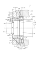
- FIG. 2 is a sectional view schematically showing a part of the shaft and the bearing structure of the rotating electric machine according to the embodiment.
- FIG. 3 is a cross-sectional view schematically showing a part of the shaft and a part of the bearing structure of the rotating electric machine according to the embodiment.
- Exemplary embodiments of the present invention are disclosed below.
- the configuration of the embodiment shown below and the effects and effects brought about by the configuration are merely examples.
- the present invention can be realized by configurations other than those disclosed in the following embodiments. Further, according to the present invention, it is possible to obtain at least one of various effects (including derivative effects) obtained by the configuration.
- drawings are schematic, and the dimensional relationship of each element, the ratio of each element, etc. may differ from reality. Furthermore, drawings may include portions with different dimensional relationships and ratios. Further, in this specification, ordinal numbers are used only to distinguish parts, members, regions, positions, directions, etc., and do not indicate order or priority.
- FIG. 1 is a sectional view schematically showing a rotating electrical machine 10 according to an embodiment.
- the rotating electric machine 10 is, for example, a squirrel cage three-phase induction motor, and is used as an electric motor or a generator. Note that the rotating electrical machine 10 is not limited to this example.
- the rotating electrical machine 10 includes a stator 11, a rotor 12, a housing 13, a shaft 14, two bearings 15A, 15B, an inner fan 16, and two cylindrical members 17A, 17B.
- the two bearings 15A and 15B will be collectively referred to as bearing 15, and the two cylindrical members 17A and 17B will be collectively referred to as cylindrical member 17.
- the rotating electrical machine 10 is not limited to this example.
- the stator 11 has a stator core 21 and a stator winding 22.
- the stator core 21 is formed into a substantially cylindrical shape surrounding the rotation center axis Ax.
- the rotation center axis Ax is the center of rotation of the rotor 12 and the shaft 14 in the rotating electric machine 10, and is, for example, a virtual straight line passing through the center of the shaft 14.
- the stator winding 22 passes through a slot provided in the stator core 21 and is attached to the stator core 21 .
- the axial direction is a direction along the rotation center axis Ax.
- the radial direction is a direction perpendicular to the rotation center axis Ax.
- the circumferential direction is the direction of rotation around the rotation center axis Ax.
- the rotor 12 has a rotor core 31 and a conductor 32.
- the rotor core 31 is formed into a substantially cylindrical shape surrounding the rotation center axis Ax, and is disposed inside the stator core 21.
- the conductors 32 are spaced apart from each other in the circumferential direction.
- the conductor 32 includes, for example, a conductor bar that passes through the rotor core 31 in the axial direction, and a shorting ring that is coupled to the ends of all the conductor bars in the axial direction.
- the housing 13 has a frame 41 and two bearing brackets 42.
- the frame 41 is formed into a substantially cylindrical shape surrounding the rotation center axis Ax.
- the stator 11 and rotor 12 are arranged inside the frame 41.
- Stator core 21 is fixed to frame 41.
- the two bearing brackets 42 are connected to both ends of the frame 41 in the axial direction.
- the bearing bracket 42 closes the space inside the frame 41.
- Each bearing bracket 42 supports a corresponding bearing 15.
- the bearing bracket 42 is provided with a hole 42a.
- the hole 42a passes through the bearing bracket 42 in the axial direction.
- the bearing 15 is inserted into the hole 42a.
- the bearing bracket 42 is also referred to as a wall.
- the shaft 14 is formed into a substantially cylindrical shape extending along the rotation center axis Ax.
- the shaft 14 passes through the bearing bracket 42 and extends both inside and outside the housing 13 .
- the shaft 14 is supported by a bearing 15 so as to be rotatable around the rotation center axis Ax.
- the shaft 14 passes inside the stator 11 and rotor 12 and extends in the axial direction.
- Shaft 14 is coupled to rotor core 31 of rotor 12 .
- the rotor 12 and the shaft 14 can rotate integrally with respect to the stator 11 around the rotation center axis Ax.
- the two bearings 15A and 15B are located on one side and the other side in the axial direction with respect to the rotor 12. That is, the rotor 12 is located between the two bearings 15A and 15B.
- the inner fan 16 is coupled to the shaft 14 inside the housing 13.
- the inner fan 16 can rotate integrally with the shaft 14 around the rotation center axis Ax.
- the inner fan 16 generates an airflow that cools the stator 11 and the rotor 12 by rotating.
- a cylindrical member 17 is provided for each bearing 15.
- the two cylindrical members 17A, 17B are located on one side and the other direction of the two bearings 15A, 15B. That is, two bearings 15A, 15B are located between two cylindrical members 17A, 17B.
- the cylindrical member 17 and the bearing 15 constitute a bearing structure 20. That is, in this embodiment, two bearing structures 20 are provided.
- FIG. 2 is a cross-sectional view schematically showing a portion of the shaft 14 and the bearing structure 20 of the rotating electric machine 10 of the embodiment.
- the bearing 15 is, for example, a rolling bearing, and includes an inner ring 15a, an outer ring 15b, and a plurality of rolling elements 15c.
- the inner ring 15a is formed in a cylindrical shape around the rotation center axis Ax, and is fixed to the shaft 14.
- the inner ring 15a is rotatable integrally with the shaft 14.
- the outer ring 15b is formed in a cylindrical shape around the rotation center axis Ax, and surrounds the inner ring 15a.
- the outer ring 15b is fixed to a bearing bracket 42 of the housing 13.
- the plurality of rolling elements 15c are arranged around the rotation center axis Ax and are interposed between the inner ring 15a and the outer ring 15b.
- the rolling element 15c is, for example, a ball (spherical body). Note that the bearing 15 is not limited to the above.
- the bearing 15 is cooled by oil.
- the oil cooling system of the bearing 15 is a forced oil cooling system.
- a supply path 15d through which oil is supplied is formed in the upper portion of the outer ring 15b in the vertical direction.
- a discharge passage 15e for discharging oil is formed in a vertically lower portion of the outer ring 15b.
- the bearing bracket 42 is formed with a supply passage 42b communicating with the supply passage 15d of the bearing 15 and a discharge passage 42c communicating with the discharge passage 15e of the bearing 15.
- the discharge path 42c has flow paths 42cb, 42cc, 42cd, 42ce, and 42cf.
- the flow path 42cb communicates with the hole 42a of the bearing bracket 42 on the opposite side of the bearing 15 from the rotor 12.
- a discharge port 42ca is formed at the lower end of the flow path 42cb in the vertical direction.
- the flow path 42cc communicates with the discharge path 15e of the bearing 15.
- the flow path 42cd communicates with the hole 42a of the bearing bracket 42 on the rotor 12 side with respect to the bearing 15.
- the flow paths 42cc and 42cd communicate with the flow path 42cb via the flow path 42ce. Further, the flow path 42cf communicates with the flow path 42cb.
- oil is supplied to the supply path 42b from an oil supply device (not shown).
- the oil supplied from the oil supply device to the supply path 42b flows into the supply path 15d, passes through the rolling elements 15c between the outer ring 15b and the inner ring 15a, and flows from the exhaust path 15e to the exhaust path 42c of the bearing bracket 42. It flows into the 42cc channel.
- the oil that has flowed into the flow path 42cc is discharged to the outside from the discharge port 42ca.
- oil leaking outward in the axial direction from between the outer ring 15b and the inner ring 15a flows into the flow paths 42cb and 42cd of the discharge path 42c of the bearing bracket 42, and is discharged from the discharge port 42ca.
- the shaft 14 has a cylindrical outer peripheral surface 14a around the rotation center axis Ax. Further, the shaft 14 has a plurality of cylindrical regions 14b to 14f around the rotation center axis Ax. Region 14b is a portion of shaft 14 to which rotor 12 is fixed. The region 14c is located on the opposite side of the rotor 12 to the region 14b and is connected to the region 14b. The diameter of region 14c is smaller than the diameter of region 14b.
- the region 14d is located on the opposite side of the rotor 12 to the region 14c and is connected to the region 14c.
- the diameter d1 of the region 14d is larger than the diameter of the region 14c.
- the region 14d is an example of a first diameter portion, and the diameter d1 of the region 14d is an example of the first diameter.
- the region 14e is located on the opposite side of the rotor 12 with respect to the region 14d and is connected to the region 14d.
- the diameter d2 of the region 14e is smaller than the diameter d1 of the region 14d.
- the region 14e is an example of a second diameter portion, and the diameter d2 of the region 14e is an example of the second diameter.
- the region 14f is located on the opposite side of the rotor 12 with respect to the region 14e and is connected to the region 14e.
- the diameter of the region 14f is smaller than the diameter d2 of the region 14e.
- the region 14c is placed inside the bearing 15.
- the region 14b and the region 14d sandwich the bearing 15 in the axial direction.
- the shaft 14 is constructed by a combination of a plurality of members.
- the shaft 14 includes a base member 51 and a fixing member 52.
- the base member 51 includes a region 14b, a region 14c, a portion 51a of the region 14d, a region 14e, and a region 14f.
- the cylindrical member 17 is located on the opposite side of the rotor 12 with respect to the bearing 15.
- the cylindrical member 17 is formed in a cylindrical shape (annular shape) around the rotation center axis Ax, and is fixed to the bearing bracket 42 of the housing 13.
- the cylindrical member 17 is made of, for example, a metal material or a synthetic resin material.
- FIG. 3 is a cross-sectional view schematically showing a part of the shaft 14 and a part of the bearing structure 20 of the rotating electrical machine 10 of the embodiment.
- the cylindrical member 17 has one end surface 17a, the other end surface 17b, an outer peripheral surface 17c, and an inner peripheral surface 17d.
- the other end surface 17b is a surface opposite to the one end surface 17a.
- the other end surface 17b is an annular plane around the rotation center axis Ax, and faces the opposite side from the bearing 15.
- the outer peripheral surface 17c is formed in a cylindrical shape around the rotation center axis Ax, and extends between the radially outer peripheral edge of the one end surface 17a and the radially outer peripheral edge of the other end surface 17b.
- the surface 17dc is spaced apart from the outer circumferential surface 14ea of the region 14e included in the outer circumferential surface 14a of the shaft 14 by a second distance t2. That is, a cylindrical gap 102 around the rotation center axis Ax is formed between the surface 17dc and the outer peripheral surface 14ea.
- the second interval t2 is smaller than the first interval t1.
- the cylindrical member 17 is integrally formed with an oil drain portion 17m and a seal portion 17n. That is, the cylindrical member 17 has an oil drain section 17m and a seal section 17n.
- a line L1 schematically indicates an example of the position of the boundary between the oil cutter 17m and the seal portion 17n.
- the oil drain portion 17m and the seal portion 17n are continuous. That is, there is no mating surface between the oil drain portion 17m and the seal portion 17n.
- the position of the boundary between the oil drain portion 17m and the seal portion 17n is not limited to the line L1.
- the cylindrical member 17 is composed of one lump of material.
- the cylindrical member 17 is made, for example, by machining a block-shaped material.
- the cylindrical member 17 is also referred to as an outer member or an integrally formed part.
- a space 103 into which oil flows is formed between the seal portion 17n and the region 14d of the shaft 14.
- Space 103 is also called a room.
- the space 103 communicates with the gap 101 between the oil cutter 17m and the area 14d.
- the cylindrical member 17 is formed with a discharge passage 17p for discharging oil.
- the discharge path 17p communicates with the space 103 and can discharge oil in the space 103.
- the discharge passage 17p communicates with the flow passage 42cf of the discharge passage 42c of the bearing bracket 42.
- the gap 101 between the surface 17da of the oil cutter 17m and the outer peripheral surface 14da of the region 14d of the shaft 14 is formed at the first gap t1 (FIG. 3) that suppresses the movement of oil from the bearing 15. has been done. That is, the oil cutter 17m prevents oil from the bearing 15 from passing through the gap 101. However, some oil may pass through the gap 101. The oil that has passed through the gap 101 flows into the space 103. At this time, the gap 102 between the surface 17dc of the seal portion 17n and the outer circumferential surface 14ea of the region 14e of the shaft 14 is a second gap t2 (see FIG. 3).
- the gap 102 between the surface 17dc of the seal portion 17n and the outer circumferential surface 14da of the shaft 14 is formed at the second gap t2 (FIG. 3) to suppress the movement of foreign matter such as dust from the outside.
- the seal portion 17n prevents foreign matter such as dust from passing through the gap 102 from the outside.
- a gap 101 between a surface 17da of the oil cutter 17m and an outer circumferential surface 14da of the shaft 14 is formed at a first gap t1 (FIG. 3) that suppresses movement of foreign matter such as dust from the outside. . That is, the oil cutter 17m prevents foreign matter from passing through the gap 101 from the outside.
- the shaft 14 also has a region 14d (first diameter portion) having a diameter d1 (first diameter) and a region 14e (second diameter portion) having a diameter d2 (second diameter) smaller than the diameter d1.
- the region 14d is located on the opposite side of the rotor 12 with respect to the bearing 15.
- the region 14e is located on the opposite side of the bearing 15 with respect to the region 14d.
- a region 14d is included in the oil drain portion 17m.
- a region 14e is included in the seal portion 17n.
- a space 103 is formed between the region 14d and the seal portion 17n.
- the space 103 communicates with the gap 101 between the oil cutter 17m and the area 14d.
- a discharge path 17p (flow path) is formed in the cylindrical member 17.
- the discharge path 17p is separate from the gap 102 between the seal portion 17n and the region 14e.
- the discharge path 17p communicates with the space 103 and discharges the oil in the space 103.
- the oil drain portion 17m and the seal portion 17n are integrally formed in the cylindrical member 17, so that the oil drain portion 17m and the seal portion 17n are provided in separate members.
- the positional accuracy of the oil drain part 17m and the seal part 17n with respect to the fixing member 52 can be increased compared to the configuration in which
Landscapes
- Engineering & Computer Science (AREA)
- General Engineering & Computer Science (AREA)
- Mechanical Engineering (AREA)
- Power Engineering (AREA)
- Motor Or Generator Frames (AREA)
Priority Applications (2)
| Application Number | Priority Date | Filing Date | Title |
|---|---|---|---|
| PCT/JP2022/023532 WO2023238409A1 (ja) | 2022-06-10 | 2022-06-10 | 回転電機 |
| JP2022576170A JP7488917B2 (ja) | 2022-06-10 | 2022-06-10 | 回転電機 |
Applications Claiming Priority (1)
| Application Number | Priority Date | Filing Date | Title |
|---|---|---|---|
| PCT/JP2022/023532 WO2023238409A1 (ja) | 2022-06-10 | 2022-06-10 | 回転電機 |
Publications (1)
| Publication Number | Publication Date |
|---|---|
| WO2023238409A1 true WO2023238409A1 (ja) | 2023-12-14 |
Family
ID=89117867
Family Applications (1)
| Application Number | Title | Priority Date | Filing Date |
|---|---|---|---|
| PCT/JP2022/023532 Ceased WO2023238409A1 (ja) | 2022-06-10 | 2022-06-10 | 回転電機 |
Country Status (2)
| Country | Link |
|---|---|
| JP (1) | JP7488917B2 (https=) |
| WO (1) | WO2023238409A1 (https=) |
Citations (2)
| Publication number | Priority date | Publication date | Assignee | Title |
|---|---|---|---|---|
| JPS62112321U (https=) * | 1986-01-06 | 1987-07-17 | ||
| JP2013204740A (ja) * | 2012-03-29 | 2013-10-07 | Sinfonia Technology Co Ltd | 軸受支持構造 |
Family Cites Families (1)
| Publication number | Priority date | Publication date | Assignee | Title |
|---|---|---|---|---|
| JPH0968231A (ja) * | 1995-08-30 | 1997-03-11 | Ntn Corp | スピンドル支持装置および軸受 |
-
2022
- 2022-06-10 JP JP2022576170A patent/JP7488917B2/ja active Active
- 2022-06-10 WO PCT/JP2022/023532 patent/WO2023238409A1/ja not_active Ceased
Patent Citations (2)
| Publication number | Priority date | Publication date | Assignee | Title |
|---|---|---|---|---|
| JPS62112321U (https=) * | 1986-01-06 | 1987-07-17 | ||
| JP2013204740A (ja) * | 2012-03-29 | 2013-10-07 | Sinfonia Technology Co Ltd | 軸受支持構造 |
Also Published As
| Publication number | Publication date |
|---|---|
| JP7488917B2 (ja) | 2024-05-22 |
| JPWO2023238409A1 (https=) | 2023-12-14 |
Similar Documents
| Publication | Publication Date | Title |
|---|---|---|
| JP5448559B2 (ja) | モータの冷却構造 | |
| US7775767B2 (en) | Fan assembly | |
| US9991769B2 (en) | Motor | |
| CN104995825B (zh) | 用于车辆和铁路车辆的电动机 | |
| JP6378285B2 (ja) | エアパージの機能を有する電動機 | |
| CN116458037A (zh) | 转子、旋转电机 | |
| US7714467B2 (en) | Electric machine with coolant guiding channel and corresponding cooling method | |
| CN114189091B (zh) | 旋转电机 | |
| JP6984383B2 (ja) | 回転機械 | |
| JP6976449B2 (ja) | 電動機 | |
| JP7488917B2 (ja) | 回転電機 | |
| JP6944418B2 (ja) | 回転電機および回転子 | |
| JP7164962B2 (ja) | 軸受装置の冷却構造 | |
| TW201338362A (zh) | 旋轉電機 | |
| JP6473128B2 (ja) | 同期回転電機および界磁巻線端部保持構造 | |
| JP2020088929A (ja) | 回転電機 | |
| JP2023171054A (ja) | 回転電機 | |
| CN115133717A (zh) | 旋转电机 | |
| JP2023044217A (ja) | 全閉型回転電機 | |
| JP7294479B1 (ja) | 回転電機 | |
| TW202220344A (zh) | 旋轉電機 | |
| JP7578149B2 (ja) | 回転電機の筐体構造 | |
| JP7771825B2 (ja) | 回転電機 | |
| JP6686664B2 (ja) | 電動ポンプ | |
| JP7826812B2 (ja) | 回転電機 |
Legal Events
| Date | Code | Title | Description |
|---|---|---|---|
| ENP | Entry into the national phase |
Ref document number: 2022576170 Country of ref document: JP Kind code of ref document: A |
|
| 121 | Ep: the epo has been informed by wipo that ep was designated in this application |
Ref document number: 22945907 Country of ref document: EP Kind code of ref document: A1 |
|
| NENP | Non-entry into the national phase |
Ref country code: DE |
|
| 122 | Ep: pct application non-entry in european phase |
Ref document number: 22945907 Country of ref document: EP Kind code of ref document: A1 |