WO2023234154A1 - 放射線検出装置、情報処理方法及びコンピュータプログラム - Google Patents
放射線検出装置、情報処理方法及びコンピュータプログラム Download PDFInfo
- Publication number
- WO2023234154A1 WO2023234154A1 PCT/JP2023/019420 JP2023019420W WO2023234154A1 WO 2023234154 A1 WO2023234154 A1 WO 2023234154A1 JP 2023019420 W JP2023019420 W JP 2023019420W WO 2023234154 A1 WO2023234154 A1 WO 2023234154A1
- Authority
- WO
- WIPO (PCT)
- Prior art keywords
- radiation detection
- detection element
- radiation
- section
- unit
- Prior art date
- Legal status (The legal status is an assumption and is not a legal conclusion. Google has not performed a legal analysis and makes no representation as to the accuracy of the status listed.)
- Ceased
Links
Images



Classifications
-
- G—PHYSICS
- G01—MEASURING; TESTING
- G01T—MEASUREMENT OF NUCLEAR OR X-RADIATION
- G01T1/00—Measuring X-radiation, gamma radiation, corpuscular radiation, or cosmic radiation
- G01T1/36—Measuring spectral distribution of X-rays or of nuclear radiation spectrometry
- G01T1/40—Stabilisation of spectrometers
-
- G—PHYSICS
- G01—MEASURING; TESTING
- G01N—INVESTIGATING OR ANALYSING MATERIALS BY DETERMINING THEIR CHEMICAL OR PHYSICAL PROPERTIES
- G01N23/00—Investigating or analysing materials by the use of wave or particle radiation, e.g. X-rays or neutrons, not covered by groups G01N3/00 – G01N17/00, G01N21/00 or G01N22/00
- G01N23/22—Investigating or analysing materials by the use of wave or particle radiation, e.g. X-rays or neutrons, not covered by groups G01N3/00 – G01N17/00, G01N21/00 or G01N22/00 by measuring secondary emission from the material
- G01N23/223—Investigating or analysing materials by the use of wave or particle radiation, e.g. X-rays or neutrons, not covered by groups G01N3/00 – G01N17/00, G01N21/00 or G01N22/00 by measuring secondary emission from the material by irradiating the sample with X-rays or gamma-rays and by measuring X-ray fluorescence
-
- G—PHYSICS
- G01—MEASURING; TESTING
- G01T—MEASUREMENT OF NUCLEAR OR X-RADIATION
- G01T7/00—Details of radiation-measuring instruments
Definitions
- the present invention relates to a radiation detection device, an information processing method, and a computer program for detecting radiation generated from a sample.
- the radiation detection element operates to detect radiation such as X-rays by applying a voltage from the outside.
- a radiation detection element using a semiconductor can detect radiation incident on the semiconductor by applying a voltage to the semiconductor.
- a current signal is output from the radiation detection element.
- a radiation detection device that includes a radiation detection element and detects radiation generated from a sample includes an illumination unit that illuminates the sample for observation of the sample.
- Patent Document 1 discloses an example of a radiation detection device including an illumination section and a radiation detection element that detects secondary electrons.
- X-ray analysis is a method of irradiating a sample with radiation such as electron beams or X-rays, detecting characteristic X-rays generated from the sample, and analyzing the sample.
- an X-ray detection element is used as a radiation detection element, and an illumination unit that illuminates the sample is also used.
- illumination light from the illumination section enters the X-ray detection element, the current signal increases and the accuracy of radiation detection deteriorates. Moreover, an increase in the current signal causes a failure of the radiation detection device. In this way, a problem may occur in the radiation detection device due to illumination light entering the X-ray detection element.
- the present invention has been made in view of the above circumstances, and its purpose is to provide a radiation detection device, an information processing method, and a computer program that can suppress defects in the radiation detection device. be.
- a radiation detection device includes an illumination unit that lights up to illuminate a sample, a radiation detection element that detects radiation generated from the sample, and a voltage that applies voltage to the radiation detection element. an application unit; and a control unit, wherein the control unit causes the voltage application unit to stop applying voltage to the radiation detection element, turns on the illumination unit, and turns off the illumination unit,
- the method is characterized in that the voltage application section starts applying voltage to the radiation detection element.
- the radiation detection device turns on the illumination unit that illuminates the sample after stopping the application of voltage to the radiation detection element for enabling radiation detection. Even if the illumination light is incident on the radiation detection element, the radiation detection element is not operating and no current signal is output from the radiation detection element. Further, the radiation detection device starts applying voltage to the radiation detection element after turning off the illumination section. Illumination light does not enter the radiation detection element that has become capable of detecting radiation. Therefore, the current signal from the radiation detection element does not increase due to the illumination light entering the radiation detection element, and no problems occur due to the increase in the current signal.
- the radiation detection device further includes a start instruction receiving unit that receives a start instruction instructing to start detecting radiation, and the control unit is configured such that the start instruction receiving unit receives the start instruction.
- the illumination section is turned off, and after the illumination section is turned off, the voltage application section is made to start applying voltage to the radiation detection element.
- the radiation detection device when receiving an instruction to start radiation detection, turns off the illumination section and starts applying voltage to the radiation detection element.
- the radiation detection device when receiving an instruction to start radiation detection, the radiation detection device turns off the illumination section and starts applying voltage to the radiation detection element.
- the user simply inputs a start instruction, radiation detection is automatically performed while preventing illumination light from entering the radiation detection element.
- the control unit after detecting radiation using the radiation detection element, causes the voltage application unit to stop applying voltage to the radiation detection element;
- the method is characterized in that the illumination section is turned on after voltage application to the radiation detection element is stopped.
- the radiation detection device stops applying voltage to the radiation detection element and turns on the illumination section. After radiation detection is performed, the sample can be observed while preventing illumination light from entering the operating radiation detection element.
- control unit may turn on the illumination unit after a predetermined standby time has elapsed after the voltage application to the radiation detection element has stopped. do.
- the radiation detection device turns on the illumination section after a predetermined standby time has elapsed after stopping the voltage application to the radiation detection element.
- the standby time is the time during which the capacitor for stabilizing the voltage is discharged and the voltage applied from the capacitor to the radiation detection element changes to a voltage at which the radiation detector does not operate. Even if the illumination light enters the radiation detection element, the radiation detection element does not perform an operation for detecting radiation, and the illumination light does not cause any adverse effects.
- the radiation detection device is characterized in that it further includes a housing that houses the radiation detection element therein, and the housing has an open opening that is not blocked.
- the radiation detection element is housed in a housing, and the housing is provided with an opening that is not covered by a window material.
- the radiation that has passed through the opening enters the radiation detection element and is detected.
- the radiation detection device is capable of detecting radiation that cannot pass through the window material due to its low energy.
- the radiation detection device includes an irradiation unit that irradiates the sample with radiation, a spectrum generation unit that generates a spectrum of radiation detected using the radiation detection element, and a spectrum generation unit that generates a spectrum of radiation detected using the radiation detection element.
- the present invention is characterized by further comprising a display unit that displays a spectrum.
- the radiation detection device irradiates a sample with radiation, generates a spectrum of radiation generated from the sample, and displays the generated spectrum on a display unit. The user can check the spectrum of radiation generated from the sample.
- a radiation detection device includes an openable and closable sample chamber in which the sample is placed, a radiation detector that is placed inside the sample chamber and has the radiation detection element, and a radiation detector that is arranged inside the sample chamber and has the radiation detection element; atmosphere adjustment by reducing the pressure inside the sample chamber or filling it with a specific gas, and introducing air from outside the sample chamber into the sample chamber in which the atmosphere has been adjusted;
- the radiation detector further includes a temperature adjustment section that adjusts the temperature of the radiation detection element, and a temperature sensor that measures the temperature inside the radiation detector, and the control section further includes a temperature adjustment section that adjusts the temperature of the radiation detection element.
- the atmosphere adjusting section is characterized in that the atmosphere adjusting section is controlled to adjust the timing of introducing air from outside the sample chamber into the sample chamber based on the temperature measured by the temperature sensor.
- the radiation detection device measures the temperature inside the radiation detector, and controls the timing of introducing outside air into the sample chamber based on the measured temperature.
- gas or moisture is adsorbed to the radiation detection element.
- control unit may cause the atmosphere adjustment unit to send the sample chamber to the inside of the sample chamber when the temperature measured by the temperature sensor exceeds a predetermined temperature threshold. It is characterized by introducing outside air.
- the radiation detection device introduces outside air into the sample chamber when the temperature inside the radiation detector is high.
- the temperature inside the radiation detector is high, the temperature of the radiation detection element is also high, and adsorption of gas or moisture to the radiation detection element is difficult to occur.
- the radiation detection device further includes an introduction instruction receiving unit that receives an introduction instruction instructing to introduce air from outside the sample chamber into the sample chamber, and the control unit It is characterized in that when the introduction instruction receiving section receives the introduction instruction, the temperature adjustment section is caused to heat the radiation detection element.
- the radiation detection device heats the radiation detection element when receiving an introduction instruction instructing to introduce external air into the sample chamber.
- the temperature of the radiation detection element can be quickly raised, and the time required to introduce outside air into the sample chamber can be shortened.
- the radiation detection device further includes an output unit that outputs a standby instruction for instructing to wait for opening of the sample chamber, and the control unit is configured such that the atmosphere adjustment unit
- the method is characterized in that the output unit outputs the standby instruction during a period before introducing air from outside into the sample chamber.
- the radiation detection device outputs a standby instruction to wait for opening of the sample chamber during a period before introducing outside air into the sample chamber.
- the standby instruction By outputting the standby instruction, the user is prevented from forcibly opening the sample chamber.
- the radiation detection device further includes a gas pressure sensor that measures the gas pressure inside the sample chamber, and the control unit causes the atmosphere adjustment unit to start adjusting the atmosphere and the gas pressure sensor to measure the gas pressure inside the sample chamber.
- the radiation detecting device is characterized in that when the measured gas pressure becomes equal to or lower than a predetermined pressure threshold, the temperature adjusting section starts cooling the radiation detecting element.
- the radiation detection device measures the gas pressure in the sample chamber, and starts cooling the radiation detection element when the gas pressure falls below a predetermined pressure threshold.
- gas or moisture is difficult to adsorb to the cooled radiation detection element, and even if a specific gas is adsorbed to the radiation detection element, problems are unlikely to occur. Therefore, occurrence of defects in the radiation detector is suppressed.
- the control unit controls the temperature adjustment unit
- the method is characterized in that cooling of the radiation detection element is started.
- the radiation detection device starts cooling the radiation detection element when a specific gas is supplied into the sample chamber for a predetermined period of time.
- a specific gas such as an inert gas
- An information processing method includes: an illumination unit that is turned on to illuminate a sample; a radiation detection element that detects radiation generated from the sample; and a voltage that applies a voltage to the radiation detection element.
- An information processing method for controlling a radiation detection apparatus comprising a voltage application section, wherein the voltage application section stops applying voltage to the radiation detection element, and after the voltage application to the radiation detection element is stopped, the illumination
- the radiation detecting element is characterized in that the radiation detecting element is turned on, the illumination part is turned off, and after the illumination part is turned off, the voltage application part is made to start applying voltage to the radiation detection element.
- a computer program includes: an illumination section that lights up to illuminate a sample; a radiation detection element that detects radiation generated from the sample; and a voltage application that applies voltage to the radiation detection element.
- a computer controlling a radiation detection device comprising a unit, the voltage application unit stops applying voltage to the radiation detection element, and after the voltage application to the radiation detection element stops, lights up the illumination unit;
- the method is characterized in that the illumination section is turned off, and after the illumination section is turned off, the voltage application section starts applying a voltage to the radiation detection element.
- the voltage application to the radiation detection element for enabling radiation detection is stopped, and then the illumination unit that illuminates the sample is turned on. Even if the illumination light is incident on the radiation detection element, the radiation detection element is not operating and no current signal is output from the radiation detection element. Further, the illumination section is turned off, and then voltage application to the radiation detection element is started. Illumination light does not enter the radiation detection element that has become capable of detecting radiation. Therefore, the current signal from the radiation detection element does not increase due to the illumination light entering the radiation detection element, and no problems occur due to the increase in the current signal.
- the present invention In the present invention, malfunctions of the radiation detection device caused by illumination light entering the radiation detection element are suppressed. Therefore, the present invention has excellent effects such as being able to stably perform radiation detection.
- FIG. 2 is a schematic cross-sectional view showing the configuration of a radiation detector.
- FIG. 3 is a schematic cross-sectional view showing a radiation detection element and a collimator.
- FIG. 2 is a block diagram showing an example of the internal configuration of a control unit.
- 3 is a flowchart illustrating an example of a procedure of processing executed by a control unit.
- 3 is a flowchart illustrating an example of a procedure of processing executed by a control unit.
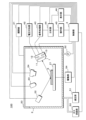
- FIG. 1 is a block diagram showing an example of the functional configuration of the radiation detection apparatus 100.
- the radiation detection device 100 is, for example, a fluorescent X-ray analysis device.
- the radiation detection apparatus 100 includes a sample stage 21 on which a sample 6 is placed, an irradiation unit 22 that irradiates the sample 6 with radiation such as an electron beam or an X-ray, an illumination unit 23 that illuminates the sample 6, and a It includes an imaging section 24 for imaging and a radiation detector 1.
- the illumination unit 23 has a light source such as an LED (light-emitting diode), and can turn on and off the light source.
- the illumination section 23 illuminates the sample 6 placed on the sample stage 21.
- the photographing section 24 photographs the sample 6 illuminated by the illumination section 23 .
- the photographing unit 24 includes an optical system and an image sensor. Radiation is irradiated from the irradiation unit 22 to the sample 6, characteristic X-rays such as fluorescent X-rays are generated in the sample 6, and the radiation detector 1 detects the characteristic X-rays generated from the sample 6. In the figure, radiation and characteristic X-rays are indicated by arrows. Note that the radiation detection apparatus 100 may be configured to hold the sample 6 by a method other than placing it on the sample stage 21.
- the radiation detection device 100 includes a sample chamber 2.
- the sample chamber 2 is box-shaped and has a cover 20 that can be opened and closed. By closing the lid part 20, the sample chamber 2 is sealed.
- An opening/closing section 41 that drives the lid section 20 to open and close is connected to the lid section 20 .
- Inside the sample chamber 2, a sample stage 21, an irradiation section 22, at least a light source of an illumination section 23, an imaging section 24, and a radiation detector 1 are arranged inside the sample chamber 2.
- the irradiation unit 22 may be configured to irradiate the sample 6 placed inside the sample chamber 2 with radiation from outside the sample chamber 2 .
- the illumination unit 23 may be configured to illuminate the sample 6 placed inside the sample chamber 2 from outside the sample chamber 2 .
- the photographing unit 24 may be configured to photograph the sample 6 placed inside the sample chamber 2 from outside the sample chamber 2 .
- the radiation detector 1 includes a radiation detection element 11, a preamplifier 12, and a temperature sensor 13. A part of the preamplifier 12 may be included inside the radiation detector 1 and another part may be arranged outside the radiation detector 1. Temperature sensor 13 measures the temperature inside radiation detector 1 . For example, the temperature sensor 13 is configured using a thermistor or a thermocouple.
- the radiation detector 1 is connected to a voltage application section 42 that applies a voltage necessary for radiation detection to the radiation detection element 11, and a signal processing section 43. Further, the voltage application section 42 applies a voltage necessary for the preamplifier 12 to operate to the preamplifier 12.
- An analysis section 44 is connected to the signal processing section 43 . The analysis section 44 is configured using a computer.
- the radiation detection device 100 includes a control section 3.
- the control section 3 is connected to an irradiation section 22, an illumination section 23, an imaging section 24, a radiation detector 1, an opening/closing section 41, a voltage application section 42, a signal processing section 43, and an analysis section 44.
- the control section 3 controls the operations of the irradiation section 22, the illumination section 23, the imaging section 24, the radiation detector 1, the opening/closing section 41, the voltage application section 42, the signal processing section 43, and the analysis section 44.
- An operation section 45 and a display section 46 are connected to the control section 3 and analysis section 44 .
- the operation unit 45 accepts input of information such as text by accepting operations from the user.
- the operation unit 45 is, for example, a touch panel, a keyboard, or a pointing device.
- the display unit 46 displays images.
- the display unit 46 is, for example, a liquid crystal display or an EL display (Electroluminescent Display).
- a drive unit 54 that drives the sample stage 21 is connected to the sample stage 21 .
- the drive unit 54 is configured using, for example, a stepping motor.
- the sample stage 21 is moved by the drive unit 54 driving the sample stage 21 .
- the sample stage 21 moves in the horizontal direction.
- the sample 6 placed on the sample stage 21 moves.
- the radiation detection device 100 may be configured without the drive unit 54.
- a pressure reducing part 51 that reduces the pressure inside the sample chamber 2 and a gas supply part 53 that supplies gas to the inside of the sample chamber 2 are connected to the sample chamber 2 .
- the radiation detection device 100 also includes a gas pressure sensor 52 that measures the pressure of gas inside the sample chamber 2 (gas pressure).
- the pressure reducing section 51 reduces the pressure inside the sample chamber 2 with the lid section 20 closed.
- the decompression unit 51 can return the gas pressure inside the sample chamber 2 to the same gas pressure as the outside of the sample chamber 2 by introducing air from outside the sample chamber 2 into the inside of the sample chamber 2.
- the pressure reducing section 51 is configured using, for example, a vacuum pump and a leak valve.
- the gas supply unit 53 supplies inert gas or dry air to the inside of the sample chamber 2 which has been reduced in pressure.
- the inside of the sample chamber 2 is filled with inert gas or dry air.
- Inert gas or dry air corresponds to a specific gas.
- the inert gas is helium.
- the gas supply unit 53 is configured using, for example, a gas tank storing inert gas or dry air and a solenoid valve.
- the pressure reducing section 51, the gas supply section 53, and the gas pressure sensor 52 are connected to the control section 3.
- the control unit 3 controls the operation of the pressure reduction unit 51 and the gas supply unit 53.
- the pressure reduction section 51 and the gas supply section 53 correspond to an atmosphere adjustment section.
- the decompression unit 51 and the gas supply unit 53 adjust the atmosphere inside the sample chamber 2 by filling the inside of the sample chamber 2 with inert gas or dry air.
- the radiation detection device 100 may be configured without using the gas supply section 53. In this form, the radiation detection device 100 does not need to include the gas supply section 53.
- the pressure reduction section 51 corresponds to an atmosphere adjustment section, and adjusts the atmosphere by reducing the pressure inside the sample chamber 2.
- the radiation detection apparatus 100 may be configured without using the decompression section 51. In this form, the radiation detection apparatus 100 does not need to include the pressure reduction section 51.
- the gas supply section 53 supplies inert gas or dry air to push out and discharge the air inside the sample chamber 2, and fills the inside of the sample chamber 2 with the inert gas or dry air. do. In this way, the gas supply section 53 of this form adjusts the atmosphere.
- FIG. 2 is a schematic cross-sectional view showing the configuration of the radiation detector 1.
- the radiation detector 1 is an SDD (Silicon Drift Detector).
- the radiation detector 1 includes a housing 17 having a cylindrical shape with a truncated cone connected to one end.
- the housing 17 is constructed by covering a plate-shaped bottom plate with a cap-shaped cover.
- An opening 171 is formed at the tip of the housing 17.
- the opening 171 is not provided with a window having a window material, and the opening 171 is not closed.
- a radiation detection element 11, a collimator 14, a circuit board 15, a temperature adjustment section 16, and a cold finger 18 are arranged inside the housing 17, a radiation detection element 11, a collimator 14, a circuit board 15, a temperature adjustment section 16, and a cold finger 18 are arranged.
- the housing 17 accommodates the radiation detection element 11 , the collimator 14 , the circuit board 15 , and the temperature adjustment section 16 .
- the temperature adjustment section 16 cools and heats the radiation detection element 11.
- the temperature adjustment section 16 is configured using, for example, a Peltier element.
- the radiation detection element 11 is mounted on the surface of the circuit board 15 and is placed at a position facing the opening 171.
- the collimator 14 has a cylindrical shape with both ends open, and is made of a material that shields radiation.
- the collimator 14 is arranged between the radiation detection element 11 and the opening 171. One end of the collimator 14 faces the opening 171, and the other end faces the surface of the radiation detection element 11. Radiation mainly passes through the opening 171 and enters the inside of the housing 17, and the collimator 14 blocks part of the radiation.
- the radiation detection element 11 detects radiation that is incident without being shielded by the collimator 14 .
- a circuit is formed on the circuit board 15, and a preamplifier 12 and a temperature sensor 13 are mounted thereon. In FIG. 2, the preamplifier 12 and temperature sensor 13 are omitted.
- the temperature sensor 13 may measure the temperature of the radiation detection element 11.
- the back surface of the circuit board 15 is in thermal contact with one end of the temperature adjustment section 16, either directly or via an intervening material.
- the other end of the temperature adjustment section 16 is in thermal contact with the cold finger 18.
- the cold finger 18 has a flat plate-shaped portion that is in thermal contact with the temperature adjustment section 16 and a portion that penetrates the bottom plate portion of the housing 17.
- the heat of the radiation detection element 11 is absorbed by the temperature adjustment section 16 through the circuit board 15, transmitted from the temperature adjustment section 16 to the cold finger 18, and is transferred through the cold finger 18. Heat is radiated to the outside of the radiation detector 1.
- the radiation detector 1 includes a plurality of lead pins 19 passing through the bottom plate portion of the housing 17.
- the lead pins 19 are connected to the circuit board 15 by a method such as wire bonding.
- Application of a voltage to the radiation detection element 11 by the voltage application section 42 and output of a signal from the preamplifier 12 are performed through the lead pin 19.
- the temperature sensor 13 is connected to the control unit 3 via a lead pin 19. Note that the radiation detector 1 may further include other components.
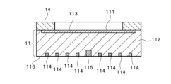
- FIG. 3 is a schematic cross-sectional view showing the radiation detection element 11 and the collimator 14.
- the radiation detection element 11 is a silicon drift type radiation detection element.
- the radiation detection element 11 has a flat plate shape as a whole.
- the radiation detection element 11 includes a plate-shaped semiconductor section 112 made of Si (silicon).
- the component of the semiconductor portion 112 is n-type Si.
- the radiation detection element 11 has an entrance surface 111 located on the entrance side where radiation to be detected is incident, and an electrode surface 116 located on the back side of the entrance surface 111. A part of the entrance surface 111 is covered with a collimator 14.
- the radiation detection element 11 is arranged such that the electrode surface 116 faces the circuit board 15 and the entrance surface 111 faces the opening 171.
- An electrode layer 113 is provided in a portion of the semiconductor portion 112 on the entrance surface 111 side.
- the electrode layer 113 is doped with a dopant that makes Si a different type of semiconductor than the components of the semiconductor portion 112 .
- the component of the electrode layer 113 is p-type Si in which Si is doped with a specific dopant such as boron, for example, p+Si.
- the electrode layer 113 is formed in most of the area along the entrance surface 111, including a portion corresponding to the center of the entrance surface 111 in plan view. For example, the shape of the electrode layer 113 is circular in plan view.
- An electrode layer 113 is formed in all areas of the incident surface 111 that correspond to the portions not covered by the collimator 14 . At the periphery of the region along the incident surface 111, there is a portion where the electrode layer 113 is not formed.
- a signal output electrode 115 which is an electrode that outputs a signal during radiation detection, is provided in a portion of the semiconductor portion 112 on the electrode surface 116 side.
- the component of the signal output electrode 115 is the same type of Si as the semiconductor portion 112.
- the component of the signal output electrode 115 is n+Si doped with a specific dopant such as phosphorus.
- a plurality of curved electrodes 114 that have multiple annular shapes in a plan view are provided in a portion of the semiconductor portion 112 on the electrode surface 116 side.
- the component of the curved electrode 114 is a different type of semiconductor than the semiconductor portion 112, and is p-type Si in which Si is doped with a specific dopant such as boron.
- the component of curved electrode 114 is p+Si.
- the plurality of curved electrodes 114 are approximately concentric, and the signal output electrode 115 is located approximately at the center of the plurality of curved electrodes 114. That is, the plurality of curved electrodes 114 surround the signal output electrode 115, and the distances between the signal output electrode 115 and each curved electrode 114 are different.
- the shape of the curved electrode 114 may be a ring other than a circular ring, and the multiple curved electrodes 114 may not be concentric.
- the shape of the curved electrode 114 may be a shape in which a part of the ring is missing.
- the signal output electrode 115 may be placed at a position other than the center of the multiple curved electrodes 114.
- the radiation detection element 11 may have a plurality of sets of signal output electrodes 115, plural curved electrodes 114, and electrode layers 113.
- the innermost curved electrode 114 and the outermost curved electrode 114 are connected to the voltage application section 42.
- a voltage is applied to the plurality of curved electrodes 114 from the voltage application unit 42 such that the innermost curved electrode 114 has the highest potential and the outermost curved electrode 114 has the lowest potential.
- the radiation detection element 11 is configured such that a predetermined electrical resistance is generated between adjacent curved electrodes 114 that are different in distance from the signal output electrode 115. For example, by adjusting the components of the portion located between adjacent curved electrodes 114, an electrical resistance channel to which two curved electrodes 114 are connected is formed. That is, the plurality of curved electrodes 114 are connected in a chain through electrical resistance.
- each curved electrode 114 has a potential that monotonically increases from the outer curved electrode 114 to the inner curved electrode 114. That is, the potential of the curved electrode 114 increases sequentially from the curved electrode 114 farther from the signal output electrode 115 to the curved electrode 114 closer to the signal output electrode 115.
- the plurality of curved electrodes 114 may include a pair of adjacent curved electrodes 114 having the same potential.
- an electric field (potential gradient) is generated in the semiconductor portion 112, in which the potential is higher as it approaches the signal output electrode 115 and becomes lower as it is farther from the signal output electrode 115.
- the electrode layer 113 is connected to the voltage application section 42 .
- a voltage is applied to the electrode layer 113 from the voltage application unit 42 so that the potential of the electrode layer 113 is between the innermost curved electrode 114 and the outermost curved electrode 114 . In this way, an electric field is generated inside the semiconductor section 112, the potential of which increases as it approaches the signal output electrode 115.
- Radiation is irradiated from the irradiation unit 22 to the sample 6, and characteristic X-rays such as fluorescent X-rays are generated in the sample 6 and enter the radiation detector 1.
- Radiation consisting of characteristic X-rays mainly passes through the opening 171 and enters the inside of the radiation detector 1. A part of the radiation that has entered the inside of the radiation detector 1 is blocked by the collimator 14. Radiation that is not blocked by the collimator 14 enters the radiation detection element 11. The radiation that has entered the radiation detection element 11 enters the semiconductor section 112.
- the radiation incident on the semiconductor section 112 is absorbed within the semiconductor section 112, and an amount of charge corresponding to the energy of the absorbed radiation is generated within the semiconductor section 112.
- the charges generated are electrons and holes.
- the generated charges are moved by the electric field inside the semiconductor section 112, and one type of charge flows into the signal output electrode 115 in a concentrated manner.
- electrons generated by the incidence of radiation move and flow into the signal output electrode 115.
- the charge flowing into the signal output electrode 115 is output as a current signal.
- the signal output electrode 115 is connected to the preamplifier 12.
- the signal output from the signal output electrode 115 is input to the preamplifier 12.
- Preamplifier 12 converts the current signal into a voltage signal.
- the preamplifier 12 outputs a signal whose intensity corresponds to the energy of the radiation.
- Preamplifier 12 is connected to signal processing section 43 .
- the radiation detector 1 outputs a signal with an intensity corresponding to the energy of the radiation to the signal processing section 43.
- the radiation detector 1 may include a control board that controls voltage application from the voltage application section 42 to the preamplifier 12. This control board performs a process of stopping voltage application from the voltage application unit 42 to the preamplifier 12 when the intensity of the signal output from the preamplifier 12 exceeds a predetermined threshold. The control board stops the operation of the preamplifier 12 by stopping the voltage application. When the illumination light enters the radiation detection element 11 and the intensity of the current signal output from the radiation detection element 11 via the preamplifier 12 increases significantly, a malfunction such as a failure may occur. The control board prevents malfunctions such as failure of the preamplifier 12 by stopping the operation of the preamplifier 12 when the output current signal is too large. The control board may be placed outside the radiation detector 1.
- the signal processing unit 43 receives the signal output by the radiation detector 1 and detects the signal value corresponding to the energy of the radiation detected by the radiation detector 1 by detecting the intensity of the signal.
- the signal processing unit 43 counts signals by signal value and outputs data indicating the relationship between the signal value and the count number to the analysis unit 44.
- the analysis unit 44 receives data indicating the relationship between the signal value and the count number output by the signal processing unit 43.
- the analysis section 44 generates a spectrum of the radiation incident on the radiation detector 1 based on the data from the signal processing section 43 . Since the signal value corresponds to the energy of the radiation and the count number corresponds to the number of times the radiation was detected, the spectrum of the radiation can be obtained from the relationship between the signal value and the count number. A spectrum shows the relationship between energy and intensity of radiation.
- the process of counting the signals output by the radiation detector 1 by signal value may be performed by the analysis unit 44 instead of the signal processing unit 43.
- the generation of the radiation spectrum may be performed by the signal processing unit 43.
- the analysis unit 44 stores spectrum data representing the spectrum of radiation.
- the signal processing section 43 and the analysis section 44 correspond to a spectrum generation section.
- the display unit 46 displays the spectrum of radiation. The user can check the spectrum of the characteristic X-rays generated from the sample 6.
- the analysis unit 44 may further perform information processing based on the radiation spectrum. For example, the analysis unit 44 performs qualitative or quantitative analysis of elements contained in the sample 6 based on the spectrum of characteristic X-rays from the sample 6.
- FIG. 4 is a block diagram showing an example of the internal configuration of the control unit 3.
- the control unit 3 is configured using a computer such as a personal computer.
- the control section 3 includes a calculation section 31, a memory 32, a reading section 33, a storage section 34, and an interface section 35.
- the calculation unit 31 is configured using, for example, a CPU (Central Processing Unit), a GPU (Graphics Processing Unit), or a multi-core CPU.
- the calculation unit 31 may be configured using a quantum computer.
- the memory 32 stores temporary data generated along with calculations.
- the memory 32 is, for example, a RAM (Random Access Memory).
- the reading unit 33 reads information from the recording medium 30 such as an optical disc or a portable memory.
- the storage unit 34 is nonvolatile, and is, for example, a hard disk or a nonvolatile semiconductor memory.
- the calculation unit 31 causes the reading unit 33 to read the computer program 341 recorded on the recording medium 30, and causes the storage unit 34 to store the read computer program 341.
- the calculation unit 31 executes processing necessary for the control unit 3 according to the computer program 341.
- the computer program 341 may be downloaded from outside the control unit 3.
- the computer program 341 may be stored in the storage unit 34 in advance. In these cases, the control section 3 does not need to include the reading section 33.
- the control unit 3 may be composed of a plurality of computers. Alternatively, the control section 3 and the analysis section 44 may be configured by the same computer.
- An operation section 45 and a display section 46 are connected to the control section 3. Other parts of the radiation detection device 100 are connected to the interface section 35.
- the user inputs various instructions to the control section 3, such as an instruction to start measurement, by operating the operation section 45.
- the control unit 3 receives instructions input using the operation unit 45.
- the display unit 46 displays images.
- the control unit 3 outputs information necessary for radiation detection by displaying an image containing the information on the display unit 46.
- the control section 3 receives information necessary for control by receiving signals from each section of the radiation detection apparatus 100 through the interface section 35.
- the control section 3 controls the operation of each section of the radiation detection apparatus 100 by transmitting control signals to each section through the interface section 35 .
- the opening 171 is not covered with a window material, and radiation passing through the opening 171 is detected. Since the radiation to be detected does not need to pass through the window material, the radiation detection device 100 has high sensitivity for detecting low-energy radiation.
- the control unit 3 executes an information processing method for controlling the radiation detection apparatus 100 so as to suppress the occurrence of defects.
- step will be abbreviated as S.
- the control unit 3 executes the following processing.
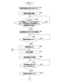
- the control unit 3 receives an instruction to adjust the atmosphere (S1).
- the calculation unit 31 displays a reception image for accepting an atmosphere adjustment instruction on the display unit 46, and when the user operates the operation unit 45, the operation unit 31 receives the atmosphere adjustment instruction.
- an image including a button for instructing atmosphere adjustment is displayed, and the user operates the operation unit 45 to specify a button on the image, thereby inputting an atmosphere adjustment instruction.
- a button for instructing atmosphere adjustment a button indicating the content of atmosphere adjustment, such as “depressurization,” “vacuum,” or “gas replacement,” may be displayed.
- the radiation detection apparatus 100 may include hardware for receiving instructions for adjusting the atmosphere, such as a push button.
- the control unit 3 starts adjusting the atmosphere inside the sample chamber 2 (S2).
- the calculation section 31 transmits a control signal to the pressure reduction section 51 through the interface section 35 in S2, thereby controlling the pressure reduction section 51 to start atmosphere adjustment.
- the control unit 3 adjusts the atmosphere by reducing the pressure inside the sample chamber 2 until the gas pressure inside the sample chamber 2 reaches a predetermined target value.
- the calculation section 31 transmits a control signal to the pressure reduction section 51 and the gas supply section 53 through the interface section 35, so as to start the atmosphere adjustment. and controls the gas supply section 53.
- the control section 3 causes the pressure reducing section 51 to reduce the pressure inside the sample chamber 2 until the gas pressure inside the sample chamber 2 reaches a predetermined target pressure, and then causes the gas supply section 53 to reduce the pressure inside the sample chamber 2.
- Inert gas or dry air is supplied to the inside of 2.
- Inert gas or dry air may be supplied from the gas supply section 53 without reducing the pressure inside the sample chamber 2. By supplying the inert gas or dry air, the inside of the sample chamber 2 is filled with the inert gas or dry air.
- the gas pressure sensor 52 measures the gas pressure inside the sample chamber 2, and the control unit 3 acquires the gas pressure measured by the gas pressure sensor 52.
- the gas pressure sensor 52 outputs a signal indicating the measured gas pressure, and the control unit 3 acquires the gas pressure by receiving the signal from the gas pressure sensor 52 at the interface unit 35.
- the control unit 3 determines whether the gas pressure measured by the gas pressure sensor 52 is below a predetermined pressure threshold, or after starting the supply of inert gas or dry air to the inside of the sample chamber 2. It is determined whether a predetermined target time has elapsed (S3). In the embodiment that does not use the gas supply unit 53, in S3, the calculation unit 31 determines whether the gas pressure is equal to or lower than the pressure threshold value.
- the pressure threshold value is a value lower than atmospheric pressure and higher than the target pressure.
- the pressure threshold value is stored in advance in the storage unit 34 or included in the computer program 341.
- the pressure threshold is, for example, 200 Pa. The fact that the gas pressure is below the pressure threshold means that the inside of the sample chamber 2 has already been depressurized.
- the calculation section 31 measures the time that has passed since the inert gas or dry air started being supplied into the sample chamber 2 .
- the calculation unit 31 determines whether the elapsed time after starting the supply of inert gas or dry air has reached a predetermined target time.
- the value of the target time is stored in advance in the storage unit 34 or included in the computer program 341. The fact that the target time has elapsed since the supply of inert gas or dry air was started means that a certain amount of inert gas or dry air has been filled inside the sample chamber 2 .
- the control unit 3 repeats the process of S3.
- the calculation section 31 repeats the process of S3 when the gas pressure exceeds the pressure threshold.
- the calculation section 31 repeats the process of S3 when the elapsed time after starting the supply of inert gas or dry air is less than the target time.
- the radiation detection apparatus 100 determines whether the gas pressure measured by the gas pressure sensor 52 is less than the pressure threshold value or the elapsed time after starting the supply of inert gas or dry air.
- a form may be adopted in which it is determined whether or not the time is exceeded.
- the control unit 3 starts cooling the radiation detection element 11 (S4).
- the calculation unit 31 causes the temperature adjustment unit 16 to start cooling the radiation detection element 11 when the gas pressure is below the pressure threshold.
- the calculation section 31 causes the temperature adjustment section 16 to start cooling the radiation detection element 11 when a target time has elapsed after starting the supply of inert gas or dry air.
- the calculation unit 31 applies a voltage for cooling the radiation detection element 11 to the Peltier element included in the temperature adjustment unit 16 by transmitting a control signal to the radiation detector 1 through the interface unit 35.
- the temperature adjustment section 16 is controlled so as to.
- the pressure inside the sample chamber 2 has already been reduced when cooling of the radiation detection element 11 is started. Since the gas such as water vapor existing inside the sample chamber 2 is diluted by the reduced pressure, it is difficult for the cooled radiation detection element 11 to adsorb gas or moisture.
- the inside of the sample chamber 2 is filled with inert gas or dry air. Since the water vapor existing inside the sample chamber 2 is diluted, water is difficult to adsorb to the cooled radiation detection element 11. Even if an inert gas or dry air is adsorbed to the cooled radiation detection element 11, the inert gas and dry air are unlikely to cause a problem in the radiation detection element 11. Therefore, the occurrence of malfunctions in the radiation detector 1 due to adsorption of gas or moisture to the cooled radiation detection element 11 is suppressed.
- the control unit 3 determines whether the adjustment of the atmosphere inside the sample chamber 2 has been completed (S5).
- the calculation section 31 acquires the gas pressure measured by the gas pressure sensor 52 in S5, and determines that the atmosphere adjustment is completed when the gas pressure has decreased to the target value. . Furthermore, when the gas pressure exceeds the target value, the calculation unit 31 determines that the atmosphere adjustment is not yet completed.
- the calculation unit 31 performs the following operations in S5 when the elapsed time from the start of supplying the inert gas or dry air to the inside of the sample chamber 2 reaches a predetermined reference time. It is determined that the atmosphere adjustment has been completed.
- the calculation unit 31 determines that the atmosphere adjustment has not been completed yet.
- the reference time is a time longer than the target time.
- the pressure of the inert gas or dry air inside the sample chamber 2 be at least one atmosphere. By setting the pressure to one atmosphere or more, air from outside the sample chamber 2 is prevented from entering.
- the reference time is predetermined so that the pressure of the supplied inert gas or dry air becomes one atmosphere or more within the sample chamber 2. If the atmosphere adjustment is not completed (S5: NO), the control unit 3 repeats the process of S5. Note that the control unit 3 may omit the process of S5.
- the control unit 3 turns on the lighting unit 23 (S6).
- the calculation unit 31 transmits a control signal to the illumination unit 23 through the interface unit 35, thereby controlling the illumination unit 23 to supply the current necessary for lighting to the light source included in the illumination unit 23.
- the control unit 3 may display on the display unit 46 that the atmosphere adjustment has been completed.
- the radiation detection apparatus 100 may include hardware for notifying that the atmosphere adjustment has been completed, such as a lamp that turns on when the atmosphere adjustment is completed.
- the sample 6 is illuminated by lighting the illumination unit 23.
- the voltage necessary for detecting radiation is not applied to the radiation detection element 11. Since no voltage is applied and the radiation detection element 11 is not operating, even if illumination light enters the radiation detection element 11, the current signal from the radiation detection element 11 will not increase and no adverse effects will occur. .
- the control unit 3 then photographs the sample 6 (S7).
- the calculation section 31 transmits a control signal to the photographing section 24 through the interface section 35, thereby causing the photographing section 24 to photograph the sample 6.
- the photographing section 24 photographs the illuminated sample 6 and transmits photographic data representing the photographed image to the control section 3 .
- the control unit 3 receives the photographed data through the interface unit 35, and the calculation unit 31 causes the display unit 46 to display the photographed image. The user can observe the sample 6 by viewing the displayed observation image.
- the control unit 3 next prepares for radiation detection (S8).
- the control unit 3 controls the drive unit 54 to move the sample 6 to a position where it is irradiated with radiation. For example, a plurality of samples 6 are placed on the sample stage 21, and one of the samples 6 is placed at a position to be irradiated with radiation. For example, by moving the sample 6, the portion of the sample 6 that is irradiated with radiation is changed. Further, the control unit 3 controls the irradiation unit 22 to adjust the focus of the radiation irradiated by the irradiation unit 22.
- control unit 3 controls the movement of the sample 6 and the focus of the radiation according to the control instruction. Make adjustments.
- the control unit 3 may perform other controls to prepare for detection of radiation in S8.
- the processes in S6 to S8 may be performed in parallel with the atmosphere adjustment process.
- the process in S6 may be performed in parallel with the depressurization inside the sample chamber 2
- the processes in S7 and S8 may be performed after the process in S3 or S5 is completed.
- the processes of S6 to S8 may be executed in parallel with the supply of inert gas or dry air to the inside of the sample chamber 2.
- the control unit 3 determines whether the radiation detection element 11 has been sufficiently cooled (S9).
- the calculation unit 31 acquires the temperature measured by the temperature sensor 13, and makes a determination based on the acquired temperature.
- the temperature sensor 13 outputs a signal indicating the measured temperature, and the control unit 3 acquires the temperature by receiving the signal from the temperature sensor 13 at the interface unit 35.
- the calculation unit 31 determines that the radiation detection element 11 is sufficiently cooled when the acquired temperature is below the reference temperature, and determines that the radiation detection element 11 is sufficiently cooled when the acquired temperature exceeds the predetermined reference temperature. It is determined that the element 11 has not been sufficiently cooled yet.
- the reference temperature is stored in advance in the storage unit 34 or included in the computer program 341.
- the calculation unit 31 may make the determination based on whether the acquired temperature is lower than the reference temperature.
- the control unit 3 repeats the process of S9. In a state where the radiation detection element 11 has not yet been sufficiently cooled, the control unit 3 prohibits the start of radiation detection.
- the control unit 3 may notify that the radiation detection element 11 is being cooled or that radiation detection cannot be started. For example, the control unit 3 displays on the display unit 46 an image including the character string “Cooling in progress”.
- the radiation detection apparatus 100 may include dedicated hardware for notifying that the radiation detection element 11 is being cooled or that radiation detection cannot be started.
- the control unit 3 receives a start instruction to start detecting radiation (S10). At this time, the control unit 3 ends leaving the fact that the radiation detection element 11 is being cooled or that radiation detection cannot be started.
- the control unit 3 receives a start instruction.
- the process in S10 corresponds to the start instruction receiving section.
- the radiation detection apparatus 100 may include hardware for receiving a start instruction such as a push button.
- the control unit 3 turns off the illumination unit 23 (S11).
- the calculation unit 31 transmits a control signal to the illumination unit 23 through the interface unit 35, thereby controlling the illumination unit 23 to stop the current supplied to the light source.
- the control unit 3 causes the voltage application unit 42 to start applying voltage to the radiation detection element 11 (S12).
- the calculation unit 31 controls the voltage application unit 42 to apply a voltage to the radiation detection element 11 by transmitting a control signal to the voltage application unit 42 through the interface unit 35.
- the voltage application unit 42 applies a voltage between the electrode layer 113, the innermost curved electrode 114, and the outermost curved electrode 114.
- the radiation detection element 11 By applying a voltage to the radiation detection element 11, the radiation detection element 11 enters a state in which it can detect radiation. Since the voltage application is started after the illumination section 23 is turned off, the illumination light from the illumination section 23 does not enter the radiation detection element 11 which is now in a state capable of detecting radiation. The current signal from the radiation detection element 11 does not increase due to the illumination light, and no adverse effects are caused by the illumination light.
- the control unit 3 next performs radiation detection (S13).
- the control unit 3 controls the irradiation unit 22 to irradiate radiation by transmitting a control signal to the irradiation unit 22 through the interface unit 35.
- the irradiation unit 22 irradiates the sample 6 with radiation, and the sample 6 generates characteristic X-rays. Radiation consisting of characteristic X-rays enters a radiation detection element 11 in the radiation detector 1, and the radiation detection element 11 outputs a current signal according to the radiation.
- the preamplifier 12 converts the current signal into a voltage signal
- the signal processing section 43 counts the signals according to the signal value corresponding to the energy of the radiation
- the analysis section 44 generates the spectrum of the radiation.
- the characteristic X-rays generated from the sample 6 are detected, and a spectrum of the characteristic X-rays is generated.
- radiation detection is automatically performed while preventing illumination light from entering the radiation detection element 11 just by the user inputting a start instruction.
- the control unit 3 stops applying voltage to the radiation detection element 11 (S14).
- the calculation unit 31 transmits a control signal to the voltage application unit 42 through the interface unit 35, thereby controlling the voltage application unit 42 to stop applying the voltage.
- the voltage application unit 42 stops applying voltage. By stopping the voltage application, the radiation detection element 11 is in a state where it cannot detect radiation.
- the control unit 3 turns on the illumination unit 23 (S15).
- the calculation section 31 waits for a predetermined standby time. The value of the waiting time is stored in advance in the storage unit 34 or included in the computer program 341.
- the calculation section 31 transmits a control signal to the illumination section 23 through the interface section 35, thereby controlling the illumination section 23 to supply the current necessary for lighting to the light source.
- the sample 6 is illuminated by lighting the illumination section 23 .
- the illumination unit 23 Since the illumination unit 23 is turned on after the voltage application to the radiation detection element 11 is stopped, even if illumination light is incident on the radiation detection element 11, the radiation detection element 11 does not perform an operation for detecting radiation. Therefore, the current signal from the radiation detection element 11 does not increase due to the illumination light, and no adverse effects occur.
- the voltage application unit 42 includes a capacitor in order to remove noise contained in the voltage applied to the radiation detection element 11 and stabilize the voltage.
- the capacitor may be arranged between the voltage application section 42 and the radiation detection element 11.
- the voltage application from the voltage application unit 42 to the radiation detection element 11 is stopped, it takes some time for the capacitor to discharge, and the voltage of the capacitor does not change immediately, so the voltage applied to the radiation detection element 11 also stops immediately. There is no change. Therefore, if the illumination unit 23 is turned on immediately after stopping the voltage application from the voltage application unit 42 to the radiation detection element 11, the illumination light will enter the radiation detection element 11 in the operating state, causing the illumination light to As a result, the current signal from the radiation detection element 11 may increase.
- the control unit 3 waits for the illumination unit 23 to turn on for a predetermined standby time after the voltage application from the voltage application unit 42 to the radiation detection element 11 is stopped.
- the standby time is the time during which the capacitor discharges and the voltage applied to the radiation detection element changes to a voltage at which the radiation detector does not operate.
- the waiting time is 2 to 3 seconds.
- the radiation detection element 11 does not perform any radiation detection operation.
- the control section 3 turns on the illumination section 23. Even if the illumination light is incident on the radiation detection element 11, the radiation detection element 11 is not performing any radiation detection operation, so the current signal from the radiation detection element 11 will not increase due to the illumination light. There are no ill effects caused by the illumination light.
- the photographing section 24 can photograph the sample 6, and the display section 46 can display the photographed image.
- the user can observe the sample 6 after radiation detection by visually checking the captured image. In this way, after radiation detection is performed, the sample 6 can be observed while preventing illumination light from entering the radiation detection element 11 in operation.
- the control unit 3 determines whether to end radiation detection (S16).
- S16 for example, when the user operates the operation unit 45 to receive an instruction to end the detection, the calculation unit 31 determines to end the radiation detection. For example, the calculation unit 31 determines to end radiation detection when radiation detection has been performed a predetermined number of times. For example, the calculation unit 31 determines to end radiation detection when a predetermined time has elapsed since the start of radiation detection. If the radiation detection is not completed (S16: NO), the calculation unit 31 returns to S7 and repeats the process for detecting radiation.
- the control unit 3 When ending radiation detection (S16: YES), the control unit 3 receives an introduction instruction to introduce air from outside the sample chamber 2 into the sample chamber 2 (S17).
- S17 when the user operates the operation unit 45, the control unit 3 receives an introduction instruction.
- the process in S17 corresponds to the installation instruction receiving section.
- the radiation detection apparatus 100 may include hardware for receiving an introduction instruction such as a push button.
- the control unit 3 outputs a standby instruction to wait for the opening of the sample chamber 2 (S18).
- the calculation unit 31 outputs the standby instruction by displaying an image including the standby instruction on the display unit 46.
- the calculation unit 31 displays on the display unit 46 an image indicating in text that the opening of the sample chamber 2 is to be waited for.
- the radiation detection apparatus 100 may be equipped with hardware for outputting a standby instruction, such as a dedicated display for displaying an image indicating in text that the sample chamber 2 is waiting for opening.
- the inside of the sample chamber 2 is in a reduced pressure state, and it is difficult to open the sample chamber 2. Furthermore, the radiation detection element 11 is in a cooled state, and when the sample chamber 2 is opened, air from outside the sample chamber 2 enters the radiation detector 1, causing gas or moisture to enter the radiation detection element 11. Adsorb. By outputting the standby instruction, the user is prevented from forcibly opening the sample chamber 2.
- the process of S18 corresponds to the output section.
- the control unit 3 causes the temperature adjustment unit 16 to heat the radiation detection element 11 (S19).
- the calculation unit 31 applies a voltage for heating the radiation detection element 11 to the Peltier element included in the temperature adjustment unit 16 by transmitting a control signal to the radiation detector 1 through the interface unit 35. Then, the temperature adjustment section 16 is controlled. By heating the radiation detection element 11, the temperature of the radiation detection element 11 can be quickly raised, and the time required to introduce outside air into the sample chamber 2 can be shortened.
- the temperature sensor 13 measures the temperature inside the radiation detector 1, and the control unit 3 acquires the temperature measured by the temperature sensor 13 (S20).
- the temperature sensor 13 outputs a signal indicating the measured temperature, and the control unit 3 acquires the temperature by receiving the signal from the temperature sensor 13 at the interface unit 35.
- the control unit 3 determines whether the obtained temperature exceeds a predetermined temperature threshold (S21).
- the control unit 3 compares the temperature measured by the temperature sensor 13 with a temperature threshold value to make a determination.
- the temperature threshold is a temperature above 0°C.
- the temperature threshold value is stored in advance in the storage unit 34 or included in the computer program 341.
- the temperature threshold is, for example, 20°C.
- the fact that the temperature measured by the temperature sensor 13 exceeds the temperature threshold means that the temperature of the radiation detection element 11 has become sufficiently high that gas adsorption or moisture adsorption to the radiation detection element 11 becomes difficult to occur. do.
- the radiation detection device 100 may be configured to determine whether the temperature is equal to or higher than a temperature threshold in S21.
- the control unit 3 If the acquired temperature is below the temperature threshold (S21: NO), the control unit 3 returns the process to S20. If the acquired temperature exceeds the temperature threshold (S21: YES), the control unit 3 introduces external air into the sample chamber 2 (S22). In the case where the gas supply unit 53 is not used, the calculation unit 31 transmits a control signal to the pressure reduction unit 51 through the interface unit 35 in S22 to introduce external air into the sample chamber 2. Controls the pressure reducing section 51. The decompression unit 51 stops decompression, introduces outside air into the sample chamber 2, and returns the gas pressure inside the sample chamber 2 to the same gas pressure as the outside. For example, the pressure reducing unit 51 introduces external air into the sample chamber 2 by stopping the vacuum pump and opening the leak valve.
- the calculation section 31 introduces external air into the sample chamber 2 by transmitting a control signal to the pressure reduction section 51 and the gas supply section 53 through the interface section 35 in S22.
- the pressure reducing section 51 and the gas supply section 53 are controlled so as to do so.
- the gas supply section 53 stops supplying inert gas or dry air, and the pressure reduction section 51 introduces external air into the sample chamber 2 to bring the gas pressure inside the sample chamber 2 to the same level as that outside.
- the decompression unit 51 allows external air to enter the sample chamber 2 by opening the leak valve while the gas supply unit 53 stops supplying inert gas or dry air and the vacuum pump stops. Introduce.
- the control unit 3 After introducing external air into the sample chamber 2, the control unit 3 ends outputting the standby instruction (S23).
- the calculation unit 31 causes the display unit 46 to finish displaying the image including the standby instruction.
- the control section 3 then opens the lid section 20 (S24).
- the calculation section 31 controls the opening/closing section 41 to open the lid section 20 by transmitting a control signal to the opening/closing section 41 through the interface section 35.
- the opening/closing section 41 opens the lid section 20
- the sample chamber 2 is placed in an open state.
- a process may be performed that allows the user to open the lid 20 manually. With the sample chamber 2 open, work such as taking out or replacing the sample 6 is performed.
- the control unit 3 ends the process.
- the control unit 3 controls the temperature so that the temperature measured by the temperature sensor 13 is equal to or higher than the temperature threshold while the lid unit 20 is open or while external air is introduced into the sample chamber 2. Controls the adjustment section 16. For example, the control unit 3 causes the temperature adjustment unit 16 to heat the radiation detection element 11 when the temperature measured by the temperature sensor 13 becomes below the temperature threshold, and causes the temperature adjustment unit 16 to heat the radiation detection element 11 when the temperature exceeds the temperature threshold. 16 to stop heating.
- the radiation detection element 11 is prevented from being cooled by external air, and gas or moisture is prevented from adsorbing to the radiation detection element 11.
- the radiation detection apparatus 100 measures the temperature inside the radiation detector 1 and, based on the temperature inside the radiation detector 1, transmits external data to the inside of the sample chamber 2. Control the timing of air introduction. Specifically, the radiation detection apparatus 100 does not introduce external air into the sample chamber 2 when the temperature inside the radiation detector 1 is low, and when the temperature inside the radiation detector 1 is high. Then, outside air is introduced into the sample chamber 2.
- the housing 17 of the radiation detector 1 is provided with an opening 171 that is not covered with a window material, and radiation passing through the opening 171 is detected. Since the radiation to be detected does not need to pass through the window material, the radiation detection device 100 can detect radiation that cannot pass through the window material due to its low energy. Therefore, the radiation detection device 100 has improved sensitivity for detecting low-energy radiation.
- gas passes through the opening 171 and enters the inside of the radiation detector 1 . If air enters the inside of the radiation detector 1 while the radiation detection element 11 is being cooled for radiation detection, gas or moisture will be adsorbed to the radiation detection element 11 .
- the sample chamber 2 is in a reduced pressure state or filled with inert gas or dry air, so that the occurrence of a problem in which gas or moisture is adsorbed to the radiation detection element 11 is suppressed.
- gas or moisture may be adsorbed to the radiation detection element 11, causing a problem.
- the radiation detection apparatus 100 stands by without introducing external air into the sample chamber 2 when the temperature inside the radiation detector 1 is low. After the temperature rises, external air is introduced into the sample chamber 2 and the sample chamber 2 is opened.
- the temperature inside the radiation detector 1 is high, the temperature of the radiation detection element 11 is also high, and adsorption of gas or moisture to the radiation detection element 11 is difficult to occur. Therefore, it is unlikely that a malfunction such as a failure will occur in the radiation detector 1 due to adsorption of gas or moisture to the radiation detection element 11. Therefore, defects in the radiation detector 1 are suppressed, and the radiation detection apparatus 100 can stably perform radiation detection.
- the radiation detection apparatus 100 controls the timing of turning on the illumination unit 23 for illuminating the sample 6 and applying voltage to the radiation detection element 11 necessary for radiation detection. Specifically, the radiation detection device 100 turns on the illumination unit 23 after stopping the voltage application to the radiation detection element 11, and starts applying the voltage to the radiation detection element 11 after turning off the illumination unit 23. .
- Illumination light from the illumination section 23 can pass through the opening 171 and enter the radiation detection element 11 .
- the radiation detection element 11 since voltage application to the radiation detection element 11 is started after the illumination unit 23 is turned off, illumination light does not enter the radiation detection element 11 that is in a state capable of detecting radiation. . Furthermore, since the illumination section 23 is turned on after the voltage application to the radiation detection element 11 is stopped, even if the illumination light is incident on the radiation detection element 11, the radiation detection element 11 is not operating and the current signal is No output. Therefore, the current signal from the radiation detection element 11 does not increase due to the illumination light from the illumination unit 23 entering the radiation detection element 11, and no problems occur due to the increase in the current signal. Therefore, malfunctions of the radiation detection device 100 are suppressed. The radiation detection device 100 can stably detect radiation.
- the radiation detection device 100 may control the voltage application from the voltage application unit 42 to the preamplifier 12 in the same way as the voltage application to the radiation detection element 11. That is, the control section 3 causes the voltage application section 42 to start applying voltage to the preamplifier 12 at the same timing as the start of voltage application to the radiation detection element 11 . Further, the control section 3 causes the voltage application section 42 to stop applying voltage to the preamplifier 12 at the same timing as when the voltage application to the radiation detection element 11 is stopped. This prevents malfunctions in the preamplifier 12 from occurring due to illumination light. Note that the voltage application from the voltage application unit 42 to the preamplifier 12 may be performed at all times while the radiation detection apparatus 100 is operating.
- the radiation detection device 100 may have a configuration in which the temperature adjustment section 16 includes a heater.
- the temperature adjustment unit 16 heats the radiation detection element 11 with a heater. By using a heater, the temperature of the radiation detection element 11 can be raised more quickly.
- the temperature adjustment section 16 may have a mechanism for adjusting the temperature other than the Peltier element or the heater.
- the radiation detection device 100 may have a configuration in which the temperature adjustment section 16 only performs cooling and does not perform heating. In this form, heating in S19 is not performed, cooling is ended, and the temperature of the radiation detection element 11 rises naturally.
- the semiconductor configuring the radiation detection element 11 is made of Si, but the radiation detection element 11 may be made of a semiconductor other than Si.
- the semiconductor portion 112 is made of an n-type semiconductor, and the electrode layer 113 and the curved electrode 114 are made of a p-type semiconductor.
- the electrode layer 113 and the curved electrode 114 may be made of an n-type semiconductor.
- the radiation detection element 11 is a silicon drift type radiation detection element, but the radiation detection element 11 may be a semiconductor element other than a silicon drift type radiation detection element. Therefore, the radiation detector 1 may be a radiation detector other than an SDD.
- the radiation detector 1 includes the collimator 14, but the radiation detector 1 may not include the collimator 14.
- the radiation detector 1 may have a configuration in which the opening 171 is not provided, the radiation detector 1 is provided with a window having a window material, and the radiation transmitted through the window is detected.
- the radiation detection element 11 is housed in the housing 17, but the radiation detector 1 may not include the housing 17.
- the radiation detection device 100 includes the irradiation unit 22, but the radiation detection device 100 may not include the irradiation unit 22.
- a mode is shown in which characteristic X-rays from the sample 6 are detected as radiation, but the radiation detection device 100 may also be configured to detect radiation other than X-rays.
- the radiation detection device 100 may use a radiation detection element 11 other than a semiconductor element.
- the radiation detection device 100 may use a photomultiplier tube as the radiation detection element 11.
- Radiation detection device 1 Radiation detector 11 Radiation detection element 13 Temperature sensor 16 Temperature adjustment section 17 Housing 171 Opening section 2 Sample chamber 20 Lid section 22 Irradiation section 23 Illumination section 24 Imaging section 3 Control section 341 Computer program 46 Display section 51 Decompression Department (atmosphere adjustment department) 52 Gas pressure sensor 53 Gas supply section (atmosphere adjustment section) 6 Sample
Landscapes
- Physics & Mathematics (AREA)
- General Physics & Mathematics (AREA)
- Health & Medical Sciences (AREA)
- Life Sciences & Earth Sciences (AREA)
- Spectroscopy & Molecular Physics (AREA)
- Molecular Biology (AREA)
- High Energy & Nuclear Physics (AREA)
- General Health & Medical Sciences (AREA)
- Immunology (AREA)
- Pathology (AREA)
- Biochemistry (AREA)
- Analytical Chemistry (AREA)
- Chemical & Material Sciences (AREA)
- Analysing Materials By The Use Of Radiation (AREA)
Priority Applications (2)
| Application Number | Priority Date | Filing Date | Title |
|---|---|---|---|
| DE112023002485.5T DE112023002485T5 (de) | 2022-05-31 | 2023-05-25 | Strahlungsdetektionsvorrichtung, informationsverarbeitungsverfahren und dazugehöriges computerprogramm |
| JP2024524787A JPWO2023234154A1 (https=) | 2022-05-31 | 2023-05-25 |
Applications Claiming Priority (2)
| Application Number | Priority Date | Filing Date | Title |
|---|---|---|---|
| JP2022-088955 | 2022-05-31 | ||
| JP2022088955 | 2022-05-31 |
Publications (1)
| Publication Number | Publication Date |
|---|---|
| WO2023234154A1 true WO2023234154A1 (ja) | 2023-12-07 |
Family
ID=89024849
Family Applications (1)
| Application Number | Title | Priority Date | Filing Date |
|---|---|---|---|
| PCT/JP2023/019420 Ceased WO2023234154A1 (ja) | 2022-05-31 | 2023-05-25 | 放射線検出装置、情報処理方法及びコンピュータプログラム |
Country Status (3)
| Country | Link |
|---|---|
| JP (1) | JPWO2023234154A1 (https=) |
| DE (1) | DE112023002485T5 (https=) |
| WO (1) | WO2023234154A1 (https=) |
Citations (4)
| Publication number | Priority date | Publication date | Assignee | Title |
|---|---|---|---|---|
| JP2000171419A (ja) * | 1998-12-04 | 2000-06-23 | Horiba Ltd | X線分析装置 |
| JP2014190791A (ja) * | 2013-03-27 | 2014-10-06 | Hitachi High-Tech Science Corp | 蛍光x線分析装置 |
| WO2019117276A1 (ja) * | 2017-12-15 | 2019-06-20 | 株式会社堀場製作所 | 放射線検出器及び放射線検出装置 |
| JP2019133787A (ja) * | 2018-01-30 | 2019-08-08 | 日本電子株式会社 | 荷電粒子線装置 |
-
2023
- 2023-05-25 WO PCT/JP2023/019420 patent/WO2023234154A1/ja not_active Ceased
- 2023-05-25 DE DE112023002485.5T patent/DE112023002485T5/de active Pending
- 2023-05-25 JP JP2024524787A patent/JPWO2023234154A1/ja active Pending
Patent Citations (4)
| Publication number | Priority date | Publication date | Assignee | Title |
|---|---|---|---|---|
| JP2000171419A (ja) * | 1998-12-04 | 2000-06-23 | Horiba Ltd | X線分析装置 |
| JP2014190791A (ja) * | 2013-03-27 | 2014-10-06 | Hitachi High-Tech Science Corp | 蛍光x線分析装置 |
| WO2019117276A1 (ja) * | 2017-12-15 | 2019-06-20 | 株式会社堀場製作所 | 放射線検出器及び放射線検出装置 |
| JP2019133787A (ja) * | 2018-01-30 | 2019-08-08 | 日本電子株式会社 | 荷電粒子線装置 |
Also Published As
| Publication number | Publication date |
|---|---|
| DE112023002485T5 (de) | 2025-05-22 |
| JPWO2023234154A1 (https=) | 2023-12-07 |
Similar Documents
| Publication | Publication Date | Title |
|---|---|---|
| Bøtter-Jensen et al. | Developments in radiation, stimulation and observation facilities in luminescence measurements | |
| US20120051514A1 (en) | Methods and systems for producing visible light and x-ray image data | |
| JP5456988B2 (ja) | マンモグラフィ装置及びそれを用いた撮影システム | |
| RU2472180C2 (ru) | Уменьшение эффектов захвата в сцинтилляторе за счет применения вторичного излучения | |
| US9892893B2 (en) | Cooled photomultiplier tube based light detector with reduced condensation, and related apparatuses and methods | |
| JP6096418B2 (ja) | X線検出装置 | |
| WO2023234153A1 (ja) | 放射線検出装置、制御方法及びコンピュータプログラム | |
| CN107957430B (zh) | X射线分析装置 | |
| CN103229043A (zh) | 量子产率测定装置 | |
| US20040109530A1 (en) | Radiation image radiographic apparatus | |
| WO2023234154A1 (ja) | 放射線検出装置、情報処理方法及びコンピュータプログラム | |
| CN118073215A (zh) | 一种原位退火多功能测试系统 | |
| JP5446182B2 (ja) | 透過型x線回折装置および透過型x線回折方法 | |
| JP2014057901A (ja) | マンモグラフィ装置及びそれを用いた撮影システム | |
| US6359962B1 (en) | Flourescent X-ray analyzer | |
| JP2004261306A (ja) | 乳房画像撮影装置 | |
| JP2009002795A (ja) | 蛍光x線分析装置 | |
| JP2006329944A (ja) | 蛍光x線分析装置 | |
| US20130223593A1 (en) | X-ray sensor, method for testing the x-ray sensor, and x-ray diagnostic device equipped with the x-ray sensor | |
| US20250224351A1 (en) | Radiation detection device and radiation detector | |
| JP2009068955A (ja) | 蛍光x線分析装置及び蛍光x線分析方法 | |
| CN119213539A (zh) | 检查装置和检查方法 | |
| JP3222572B2 (ja) | X線分析装置 | |
| KR101602733B1 (ko) | 웨이퍼 검사장치 및 웨이퍼 검사방법 | |
| JP4455746B2 (ja) | ランプハウス及び光放射装置 |
Legal Events
| Date | Code | Title | Description |
|---|---|---|---|
| 121 | Ep: the epo has been informed by wipo that ep was designated in this application |
Ref document number: 23815912 Country of ref document: EP Kind code of ref document: A1 |
|
| WWE | Wipo information: entry into national phase |
Ref document number: 2024524787 Country of ref document: JP |
|
| WWE | Wipo information: entry into national phase |
Ref document number: 112023002485 Country of ref document: DE |
|
| WWP | Wipo information: published in national office |
Ref document number: 112023002485 Country of ref document: DE |
|
| 122 | Ep: pct application non-entry in european phase |
Ref document number: 23815912 Country of ref document: EP Kind code of ref document: A1 |