WO2023228743A1 - 光ファイバ - Google Patents
光ファイバ Download PDFInfo
- Publication number
- WO2023228743A1 WO2023228743A1 PCT/JP2023/017565 JP2023017565W WO2023228743A1 WO 2023228743 A1 WO2023228743 A1 WO 2023228743A1 JP 2023017565 W JP2023017565 W JP 2023017565W WO 2023228743 A1 WO2023228743 A1 WO 2023228743A1
- Authority
- WO
- WIPO (PCT)
- Prior art keywords
- optical fiber
- refractive index
- core
- index difference
- relative refractive
- Prior art date
Links
- 239000013307 optical fiber Substances 0.000 title claims abstract description 57
- VYPSYNLAJGMNEJ-UHFFFAOYSA-N Silicium dioxide Chemical compound O=[Si]=O VYPSYNLAJGMNEJ-UHFFFAOYSA-N 0.000 claims abstract description 27
- 238000005253 cladding Methods 0.000 claims abstract description 18
- 239000011521 glass Substances 0.000 claims description 14
- 239000000377 silicon dioxide Substances 0.000 claims description 9
- 230000005540 biological transmission Effects 0.000 description 34
- 229910052736 halogen Inorganic materials 0.000 description 16
- 150000002367 halogens Chemical class 0.000 description 16
- 238000009826 distribution Methods 0.000 description 9
- 238000010521 absorption reaction Methods 0.000 description 6
- 230000007423 decrease Effects 0.000 description 6
- 239000000460 chlorine Substances 0.000 description 4
- 230000000694 effects Effects 0.000 description 4
- 238000013459 approach Methods 0.000 description 2
- 239000002585 base Substances 0.000 description 2
- 229910052801 chlorine Inorganic materials 0.000 description 2
- 239000006185 dispersion Substances 0.000 description 2
- 239000000835 fiber Substances 0.000 description 2
- 229910052731 fluorine Inorganic materials 0.000 description 2
- 238000010438 heat treatment Methods 0.000 description 2
- 239000012535 impurity Substances 0.000 description 2
- 239000000463 material Substances 0.000 description 2
- 238000000034 method Methods 0.000 description 2
- 239000011734 sodium Substances 0.000 description 2
- ZAMOUSCENKQFHK-UHFFFAOYSA-N Chlorine atom Chemical compound [Cl] ZAMOUSCENKQFHK-UHFFFAOYSA-N 0.000 description 1
- PXGOKWXKJXAPGV-UHFFFAOYSA-N Fluorine Chemical compound FF PXGOKWXKJXAPGV-UHFFFAOYSA-N 0.000 description 1
- DGAQECJNVWCQMB-PUAWFVPOSA-M Ilexoside XXIX Chemical compound C[C@@H]1CC[C@@]2(CC[C@@]3(C(=CC[C@H]4[C@]3(CC[C@@H]5[C@@]4(CC[C@@H](C5(C)C)OS(=O)(=O)[O-])C)C)[C@@H]2[C@]1(C)O)C)C(=O)O[C@H]6[C@@H]([C@H]([C@@H]([C@H](O6)CO)O)O)O.[Na+] DGAQECJNVWCQMB-PUAWFVPOSA-M 0.000 description 1
- WHXSMMKQMYFTQS-UHFFFAOYSA-N Lithium Chemical compound [Li] WHXSMMKQMYFTQS-UHFFFAOYSA-N 0.000 description 1
- ZLMJMSJWJFRBEC-UHFFFAOYSA-N Potassium Chemical compound [K] ZLMJMSJWJFRBEC-UHFFFAOYSA-N 0.000 description 1
- 229910052783 alkali metal Inorganic materials 0.000 description 1
- 238000000149 argon plasma sintering Methods 0.000 description 1
- 238000005452 bending Methods 0.000 description 1
- 230000007547 defect Effects 0.000 description 1
- 230000018044 dehydration Effects 0.000 description 1
- 238000006297 dehydration reaction Methods 0.000 description 1
- 230000000779 depleting effect Effects 0.000 description 1
- 238000003795 desorption Methods 0.000 description 1
- 230000006866 deterioration Effects 0.000 description 1
- 239000011737 fluorine Substances 0.000 description 1
- 229910052744 lithium Inorganic materials 0.000 description 1
- 238000004519 manufacturing process Methods 0.000 description 1
- 230000004048 modification Effects 0.000 description 1
- 238000012986 modification Methods 0.000 description 1
- 230000003287 optical effect Effects 0.000 description 1
- 230000002093 peripheral effect Effects 0.000 description 1
- 229910052700 potassium Inorganic materials 0.000 description 1
- 239000011591 potassium Substances 0.000 description 1
- 229910052701 rubidium Inorganic materials 0.000 description 1
- IGLNJRXAVVLDKE-UHFFFAOYSA-N rubidium atom Chemical compound [Rb] IGLNJRXAVVLDKE-UHFFFAOYSA-N 0.000 description 1
- 235000012239 silicon dioxide Nutrition 0.000 description 1
- 238000005245 sintering Methods 0.000 description 1
- 229910052708 sodium Inorganic materials 0.000 description 1
- 238000005728 strengthening Methods 0.000 description 1
Images


Classifications
-
- G—PHYSICS
- G02—OPTICS
- G02B—OPTICAL ELEMENTS, SYSTEMS OR APPARATUS
- G02B6/00—Light guides; Structural details of arrangements comprising light guides and other optical elements, e.g. couplings
- G02B6/02—Optical fibres with cladding with or without a coating
- G02B6/036—Optical fibres with cladding with or without a coating core or cladding comprising multiple layers
Definitions
- the present disclosure relates to optical fibers.
- This application claims priority based on Japanese Application No. 2022-086237 filed on May 26, 2022, and incorporates all the contents described in the said Japanese application.
- the transmission loss value at wavelengths in the near-infrared region is made up of the sum of multiple scattering/absorption factors such as Rayleigh scattering, infrared absorption, OH absorption, and structural asymmetric scattering.
- Rayleigh scattering, infrared absorption, and OH absorption are atomic-scale scattering and absorption effects of glass.
- Structural asymmetric scattering is an effect caused by variations in the refractive index distribution on a scale slightly larger than the atomic scale affecting light scattering.
- One of the methods for producing an optical fiber with low transmission loss is to reduce Rayleigh scattering by reducing the concentration of added halogen elements. It is known that Rayleigh scattering is caused by localized unevenness in the concentration distribution on an atomic scale and tends to increase in proportion to the concentration. Patent Documents 1 to 3 describe optical fibers in which the concentration of added halogen elements is reduced. Non-Patent Document 1 describes that Rayleigh scattering due to density unevenness tends to increase in proportion to the density.
- An optical fiber includes a core made of silica-based glass and a cladding made of silica-based glass that surrounds the core, and has a radial distance r from the central axis of the core and a radius of the core. If a, the maximum value ⁇ 1 of the relative refractive index difference when 0 ⁇ r/a ⁇ 0.3 and the minimum value ⁇ 2 of the relative refractive index difference when 0 ⁇ r/a ⁇ 0.9 are ⁇ 1 ⁇ 2 ⁇ 0. Satisfies .02.
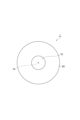
- FIG. 1 is a sectional view showing an optical fiber according to an embodiment.
- FIG. 2 is a graph showing the refractive index distribution of the optical fiber according to the embodiment.
- FIG. 3 is a graph showing the results of organizing the relationship between refractive index distribution and transmission loss.
- FIG. 4 is a graph showing the relationship between ( ⁇ 3- ⁇ 2)/( ⁇ 1- ⁇ 2) and the root mean square of the relative refractive index difference of the core.
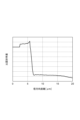
- FIG. 5 is a graph showing the refractive index distribution of the optical fiber according to Experimental Example 3.
- the halogen element added to the optical fiber base material not only contributes to adjusting the increase/decrease in the refractive index but also has the effect of removing impurities present inside the glass at the time of the base material. Therefore, if an attempt is made to suppress the amount of the halogen element added to zero, the transmission loss will rather worsen.
- the refractive index is highest at the center of the core and tends to decrease toward the outside in the radial direction due to desorption of the halogen element at the center of the core.
- variations in the refractive index within the core increase, resulting in the influence of structural asymmetric scattering, which worsens transmission loss.
- An object of the present disclosure is to provide an optical fiber that can reduce transmission loss.
- An optical fiber according to one aspect of the present disclosure includes a core made of silica-based glass and a cladding made of silica-based glass that surrounds the core, and the radial distance from the central axis of the core is r, and the core is made of silica-based glass.
- the radius of is a
- the maximum value ⁇ 1 of the relative refractive index difference when 0 ⁇ r/a ⁇ 0.3 and the minimum value ⁇ 2 of the relative refractive index difference when 0 ⁇ r/a ⁇ 0.9 are ⁇ 1 ⁇ ⁇ 2 ⁇ 0.02 is satisfied.
- This optical fiber can reduce transmission loss.
- the maximum value ⁇ 1, the minimum value ⁇ 2, and the maximum value ⁇ 3 of the relative refractive index difference at 0.8 ⁇ r/a ⁇ 1 are 0.5 ⁇ ( ⁇ 3 ⁇ 2)/( ⁇ 1 ⁇ 2) ⁇ 1.5 may be satisfied. In this case, transmission loss can be further reduced.
- the minimum value ⁇ 4 of the relative refractive index difference of the cladding may be ⁇ 0.6 ⁇ 4 ⁇ 0.2. In this case, transmission loss can be further reduced.
- the maximum value ⁇ 1 and the minimum value ⁇ 2 may satisfy ⁇ 1 ⁇ 2 ⁇ 0.04. In this case, transmission loss can be further reduced.
- the maximum value ⁇ 1 and the minimum value ⁇ 2 may satisfy ⁇ 1 ⁇ 2 ⁇ 0.06. In this case, transmission loss can be further reduced.
- FIG. 1 is a cross-sectional view showing an optical fiber according to an embodiment.
- the optical fiber 1 includes a core 10 extending along the central axis 1a and a cladding 20 surrounding the core 10.
- the core 10 and the cladding 20 are made of silica-based glass whose main component is silica glass, in which the mass ratio of silica glass is 90% or more.
- the core 10 contains, for example, halogen elements such as fluorine (F) and chlorine (Cl), and alkali metal elements such as lithium (Li), sodium (Na), potassium (K), and rubidium (Rb).
- the cladding 20 may contain, for example, halogen elements such as F and Cl.
- the refractive index of the core 10 is higher than the refractive index of the cladding 20.
- the effective cross-sectional area Aeff of the optical fiber 1 at a wavelength of 1550 nm is 80 ⁇ m 2 or more and 160 ⁇ m 2 or less.
- the transmission loss of the optical fiber 1 at a wavelength of 1550 nm is 0.150 dB/km or less.
- the radius a of the core 10 is, for example, 4 ⁇ m or more and 7 ⁇ m or less.
- FIG. 2 is a graph showing the refractive index distribution of the optical fiber according to the embodiment.
- the vertical axis shows the relative refractive index difference ⁇ [%] based on the refractive index of pure silica (SiO 2 ), and the horizontal axis shows the radial distance r [ ⁇ m] from the central axis 1a of the core 10.
- the position where the value d ⁇ (r)/dr obtained by differentiating the relative refractive index difference ⁇ (r) with respect to the radial distance r has the minimum value (steepest downward slope) is defined as the interface (boundary) between the core 10 and the cladding 20. be done.
- the radial distance r between the interface between the core 10 and the cladding 20 corresponds to the radius a of the core 10.
- the maximum value (local maximum value) of the relative refractive index difference is ⁇ 1 [%], and the relative refractive index difference is ⁇ 1.
- the radial distance be r1.
- the minimum radial distance is defined as r1
- the local maximum value is defined as the maximum value ⁇ 1.
- ⁇ 1 satisfies -0.1 ⁇ 1 ⁇ 0.1. 0 ⁇ r1/a ⁇ 0.1 may be satisfied.
- the minimum value (minimum value) of the relative refractive index difference is ⁇ 2 [%], and the relative refractive index difference is ⁇ 2.
- the radial distance be r2. If a plurality of minimum values exist, the minimum radial distance is defined as r2, and the minimum value is defined as the minimum value ⁇ 2. ⁇ 2 satisfies -0.2 ⁇ 2 ⁇ 0. However, ⁇ 1 ⁇ 2. 0 ⁇ r2/a ⁇ 0.5, 0 ⁇ r2/a ⁇ 0.4, and 0 ⁇ r2/a ⁇ 0.35.
- the maximum value (local maximum value) of the relative refractive index difference is ⁇ 3 [%], and the relative refractive index difference is ⁇ 3.
- the radial distance be r3.
- the maximum radial distance is defined as r3, and the local maximum value is defined as the maximum value ⁇ 3.
- ⁇ 3 satisfies -0.1 ⁇ 3 ⁇ 0.1.
- the minimum value (minimum value) of the relative refractive index difference is ⁇ 4 [%]
- the radial distance at which the relative refractive index difference is ⁇ 4 is r4. If a plurality of minimum values exist, the minimum radial distance is defined as r4, and the minimum value is defined as the minimum value ⁇ 4. ⁇ 4 may be ⁇ 0.6 ⁇ 4 ⁇ 0.2.
- the maximum value ⁇ 1 and the minimum value ⁇ 2 satisfy ⁇ 1 ⁇ 2 ⁇ 0.02. Further, the maximum value ⁇ 1, the minimum value ⁇ 2, and the maximum value ⁇ 3 satisfy 0.5 ⁇ ( ⁇ 3 ⁇ 2)/( ⁇ 1 ⁇ 2) ⁇ 1.5.
- ( ⁇ 3- ⁇ 2)/( ⁇ 1- ⁇ 2) is an index indicating the variation in the relative refractive index difference ⁇ within the core 10. The closer the maximum value ⁇ 1 at the center of the core 10 and the maximum value ⁇ 3 at the outer periphery are to each other, the closer ( ⁇ 3 ⁇ 2)/( ⁇ 1 ⁇ 2) approaches 1.
- the optical fiber 1 according to this embodiment is realized by the following means.
- the maximum value ⁇ 1 was achieved by locally depleting the halogen concentration, especially the F concentration, in the center of the core 10. Local depletion of the F concentration can be achieved, for example, by locally heating the glass portion corresponding to the center of the core 10 in the optical fiber preform after impurities have been removed in a dehydration process. This heating temperature may be 1000°C or higher, or 1400°C or higher.
- the Cl concentration and F concentration at the position of the radial distance r1 may each be 1000 wtppm or less, or 500 wtppm or less.
- the amount of halogen added is adjusted during sintering of the glass body that will become the core so that the halogen concentration at the outer periphery of the core is reduced.
- the F concentration in the cladding portion is 10,000 wtppm or more
- the halogen concentration in the outer peripheral portion of the core portion is too low, the difference in glass viscosity at the interface between the core portion and the cladding portion will become large. As a result, defects that lead to increased transmission loss are likely to occur at the interface. Therefore, at the position of the radial distance r3 corresponding to the interface position between the core 10 and the cladding 20, the halogen concentration may be 100 wtppm or more, or 500 wtppm or more.
- FIG. 3 is a graph showing the results of organizing the relationship between refractive index distribution and transmission loss.
- the transmission loss is ( ⁇ 3- ⁇ 2)/( ⁇ 1- ⁇ 2). The relationship between is plotted. Note that the value of ⁇ 1 ⁇ 2 for each optical fiber includes an error of ⁇ 0.005%.
- ⁇ 1- ⁇ 2 ⁇ 0.02 may be satisfied, and ⁇ 1- ⁇ 2 ⁇ 0.04. It can be confirmed that ⁇ 1 ⁇ 2 ⁇ 0.06 may be satisfied.
- ⁇ 1 ⁇ 2 ⁇ 0.02 a transmission loss of 0.150 dB/km or less can be achieved.
- ⁇ 1 ⁇ 2 ⁇ 0.04 a transmission loss of 0.1495 dB/km or less can be achieved.
- ⁇ 1 ⁇ 2 ⁇ 0.06 a transmission loss of 0.149 dB/km or less can be achieved.
- ⁇ 1- ⁇ 2 corresponds to the amount of decrease in the halogen concentration at the center of the core 10, and as the halogen concentration decreases, Rayleigh scattering due to concentration unevenness decreases, resulting in a reduction in transmission loss. Suggests.
- FIG. 4 is a graph showing the relationship between ( ⁇ 3 ⁇ 2)/( ⁇ 1 ⁇ 2) and the root mean square (RMS) of the relative refractive index difference of the core.
- the RMS of the relative refractive index difference of the core is the mean square variation ( ⁇ (r) - ⁇ e) of the relative refractive index difference ⁇ (r) with respect to the effective relative refractive index difference ⁇ e in the range of 0 ⁇ r ⁇ r3. It is the square root of the average value in the range r ⁇ r3.
- the mean square variation ( ⁇ (r) ⁇ e) 2 also decreases. It can be confirmed that this reduces structural asymmetric scattering and, as a result, reduces transmission loss.
- the optical fiber of Experimental Example 1 corresponds to the optical fiber 1 according to the embodiment, and has a refractive index profile in which the relative refractive index difference increases at the radial distances r1 and r3.
- the optical fiber according to Experimental Example 2 has a refractive index profile in which the relative refractive index difference is high at the radial distance r1 and the relative refractive index difference is low at the radial distance r3. As shown in FIG.
- the optical fiber according to Experimental Example 3 has a typical ring core-shaped refractive index profile in which the relative refractive index difference is high at the radial distance r3 and the relative refractive index difference is low at the radial distance r1. have. It can be said that the optical fiber according to Experimental Example 1 also has a ring core-shaped refractive index profile.
- the optical fiber according to Experimental Example 4 has a refractive index profile in which the relative refractive index difference is low at both the radial distances r1 and r3.
- Table 1 shows, for each optical fiber, ⁇ 1- ⁇ 2 [%], ⁇ 3- ⁇ 2 [%], transmission loss [dB/km] at a wavelength of 1550 nm, effective cross-sectional area Aeff [ ⁇ m 2 ] at a wavelength of 1550 nm, and Chromatic dispersion [ps/nm/km] and fiber cutoff wavelength ⁇ c [nm] are shown.
- the optical fiber of Experimental Example 1 has the lowest transmission loss. This is considered to be because the halogen concentration of the core was reduced by having a protruding refractive index profile at the center of the core due to a drop in halogen concentration. Furthermore, it can be confirmed that the optical fiber of Experimental Example 1 has almost the same characteristics as the optical fiber of Experimental Example 3 in effective cross-sectional area Aeff, wavelength dispersion, and fiber cutoff wavelength ⁇ c.
- Optical fiber 1a Central axis 10
- Core 20 ... Clad
Landscapes
- Physics & Mathematics (AREA)
- General Physics & Mathematics (AREA)
- Optics & Photonics (AREA)
- Glass Compositions (AREA)
Abstract
光ファイバは、シリカ系ガラスからなるコア(10)と、コア(10)を取り囲み、シリカ系ガラスからなるクラッド(20)と、を備え、コア(10)の中心軸からの径方向距離をr、コア(10)の半径をaとすると、0≦r/a≦0.3における比屈折率差の最大値Δ1、及び、0≦r/a≦0.9における比屈折率差の最小値Δ2は、Δ1-Δ2≧0.02を満たす。
Description
本開示は、光ファイバに関する。本出願は、2022年5月26日出願の日本出願第2022-086237号に基づく優先権を主張し、前記日本出願に記載された全ての記載内容を援用するものである。
近赤外領域の波長における伝送損失値は、レイリ散乱、赤外吸収、OH吸収、構造不整散乱等の複数の散乱・吸収要因の足し合わせで成り立っている。レイリ散乱、赤外吸収、及びOH吸収は、ガラスの原子スケールでの散乱・吸収効果である。構造不整散乱は、原子スケールよりやや大きいスケールでの屈折率分布のばらつきが光の散乱に影響することにより生じる効果である。
伝送損失の低い光ファイバを作製する手段の一つとして、添加ハロゲン元素の濃度を減少させることによりレイリ散乱を低減するという手法がある。レイリ散乱は、原子スケールで局在する濃度分布のむらに起因し、濃度に比例して増加する傾向にあることが知られている。特許文献1から3には、添加ハロゲン元素の濃度が低減された光ファイバが記載されている。非特許文献1には、濃度むらによるレイリ散乱は濃度に比例して増加する傾向にあることが記載されている。
H. Kakiuchida et al. "Rayleigh Scattering in Fluorine-Doped Silica Glass" Journal of Japan Applied Physics Vol. 42 (2003), pp. 6516-6517, Part 1, No. 10, October 2003
本開示の一態様に係る光ファイバは、シリカ系ガラスからなるコアと、コアを取り囲み、シリカ系ガラスからなるクラッドと、を備え、コアの中心軸からの径方向距離をr、コアの半径をaとすると、0≦r/a≦0.3における比屈折率差の最大値Δ1、及び、0≦r/a≦0.9における比屈折率差の最小値Δ2は、Δ1-Δ2≧0.02を満たす。
[本開示が解決しようとする課題]
光ファイバ母材に添加されたハロゲン元素は、屈折率の増減の調整に寄与するのみならず、母材時点でのガラス内部にある不純物を除去する効果を有している。よって、ハロゲン元素の添加量をゼロに抑えようとするとむしろ伝送損失が悪化する。
光ファイバ母材に添加されたハロゲン元素は、屈折率の増減の調整に寄与するのみならず、母材時点でのガラス内部にある不純物を除去する効果を有している。よって、ハロゲン元素の添加量をゼロに抑えようとするとむしろ伝送損失が悪化する。
特許文献1から3に記載の光ファイバでは、コア中心部のハロゲン元素が脱離することにより、屈折率がコア中心部で最も高く、径方向に外側に向かって減少傾向を示している。このため、コア内で屈折率のばらつきが大きくなる結果、構造不整散乱の影響を受け、伝送損失が悪化する。
本開示は、伝送損失を低減可能な光ファイバを提供することを目的とする。
[本開示の効果]
本開示によれば、伝送損失を低減可能な光ファイバを提供することができる。
本開示によれば、伝送損失を低減可能な光ファイバを提供することができる。
[本開示の実施態様の説明]
最初に本開示の実施態様を列記して説明する。(1)本開示の一態様に係る光ファイバは、シリカ系ガラスからなるコアと、コアを取り囲み、シリカ系ガラスからなるクラッドと、を備え、コアの中心軸からの径方向距離をr、コアの半径をaとすると、0≦r/a≦0.3における比屈折率差の最大値Δ1、及び、0≦r/a≦0.9における比屈折率差の最小値Δ2は、Δ1-Δ2≧0.02を満たす。この光ファイバでは、伝送損失を低減可能である。
最初に本開示の実施態様を列記して説明する。(1)本開示の一態様に係る光ファイバは、シリカ系ガラスからなるコアと、コアを取り囲み、シリカ系ガラスからなるクラッドと、を備え、コアの中心軸からの径方向距離をr、コアの半径をaとすると、0≦r/a≦0.3における比屈折率差の最大値Δ1、及び、0≦r/a≦0.9における比屈折率差の最小値Δ2は、Δ1-Δ2≧0.02を満たす。この光ファイバでは、伝送損失を低減可能である。
(2)上記(1)において、最大値Δ1、最小値Δ2、及び、0.8≦r/a≦1における比屈折率差の最大値Δ3は、0.5≦(Δ3-Δ2)/(Δ1-Δ2)≦1.5を満たしてもよい。この場合、伝送損失を更に低減可能である。
(3)上記(1)または(2)において、比屈折率差が最大値Δ1となる径方向距離をr1とすると、0≦r1/a≦0.1であってもよい。この場合、伝送損失を低減可能である。
(4)上記(1)から(3)のいずれかにおいて、比屈折率差が最小値Δ2となる径方向距離をr2とすると、0≦r2/a≦0.5であってもよい。この場合、伝送損失を更に低減可能である。
(5)上記(1)から(3)のいずれかにおいて、比屈折率差が最小値Δ2となる径方向距離をr2とすると、0≦r2/a≦0.4であってもよい。この場合、伝送損失を更に低減可能である。
(6)上記(1)から(3)のいずれかにおいて、比屈折率差が最小値Δ2となる径方向距離をr2とすると、0≦r2/a≦0.35であってもよい。この場合、伝送損失を更に低減可能である。
(7)上記(1)から(6)のいずれかにおいて、クラッドの比屈折率差の最小値Δ4は、-0.6≦Δ4≦-0.2であってもよい。この場合、伝送損失を更に低減可能である。
(8)上記(1)から(7)のいずれかにおいて、最大値Δ1、及び、最小値Δ2は、Δ1-Δ2≧0.04を満たしてもよい。この場合、伝送損失を更に低減可能である。
(9)上記(1)から(7)のいずれかにおいて、最大値Δ1、及び、最小値Δ2は、Δ1-Δ2≧0.06を満たしてもよい。この場合、伝送損失を更に低減可能である。
[本開示の実施形態の詳細]
本開示の光ファイバの具体例を、以下に図面を参照しつつ説明する。なお、本発明はこれらの例示に限定されるものではなく、特許請求の範囲によって示され、特許請求の範囲と均等の意味及び範囲内でのすべての変更が含まれることが意図される。図面の説明において同一の要素には同一の符号を付し、重複する説明を省略する。
本開示の光ファイバの具体例を、以下に図面を参照しつつ説明する。なお、本発明はこれらの例示に限定されるものではなく、特許請求の範囲によって示され、特許請求の範囲と均等の意味及び範囲内でのすべての変更が含まれることが意図される。図面の説明において同一の要素には同一の符号を付し、重複する説明を省略する。
図1は、実施形態に係る光ファイバを示す断面図である。図1に示されるように、光ファイバ1は、中心軸1aに沿って延びるコア10と、コア10を取り囲むクラッド20と、を備える。コア10及びクラッド20は、シリカガラスが質量比で90%以上である、シリカガラスを主成分とするシリカ系ガラスからなる。コア10は、例えば、フッ素(F)、塩素(Cl)等のハロゲン元素、及び、リチウム(Li)、ナトリウム(Na)、カリウム(K)、ルビジウム(Rb)等のアルカリ金属元素を含んでいる。クラッド20は、例えば、F、Cl等のハロゲン元素を含んでいてもよい。
コア10の屈折率は、クラッド20の屈折率よりも高い。光ファイバ1の波長1550nmにおける実効断面積Aeffは、80μm2以上160μm2以下である。光ファイバ1の波長1550nmにおける伝送損失は、0.150dB/km以下である。コア10の半径aは、例えば、4μm以上7μm以下である。
図2は、実施形態に係る光ファイバの屈折率分布を示すグラフである。縦軸は、純シリカ(SiO2)の屈折率を基準とした比屈折率差Δ[%]を示し、横軸は、コア10の中心軸1aからの径方向距離r[μm]を示す。比屈折率差Δ(r)を径方向距離rで微分した値dΔ(r)/drが最小値(最急の下り勾配)となる位置は、コア10及びクラッド20の界面(境界)として定義される。コア10及びクラッド20の界面の径方向距離rは、コア10の半径aに相当する。
径方向距離rが半径aに対して0≦r/a≦0.3を満たす径方向範囲において、比屈折率差の最大値(極大値)をΔ1[%]、比屈折率差がΔ1となる径方向距離をr1とする。複数の極大値が存在する場合は、最小の径方向距離をr1と定義し、その極大値を最大値Δ1とする。Δ1は、-0.1≦Δ1≦0.1を満たす。0≦r1/a≦0.1であってもよい。
径方向距離rが半径aに対して0≦r/a≦0.9を満たす径方向範囲において、比屈折率差の最小値(極小値)をΔ2[%]、比屈折率差がΔ2となる径方向距離をr2とする。複数の極小値が存在する場合は、最小の径方向距離をr2と定義し、その極小値を最小値Δ2とする。Δ2は、-0.2≦Δ2≦0を満たす。ただし、Δ1≧Δ2である。0≦r2/a≦0.5であってもよく、0≦r2/a≦0.4であってもよく、0≦r2/a≦0.35であってもよい。
径方向距離rが半径aに対して0.8≦r/a≦1を満たす径方向範囲において、比屈折率差の最大値(極大値)をΔ3[%]、比屈折率差がΔ3となる径方向距離をr3とする。複数の極大値が存在する場合は、最大の径方向距離をr3と定義し、その極大値を最大値Δ3とする。Δ3は、-0.1≦Δ3≦0.1を満たす。ただし、Δ3≧Δ2である。
r≧aを満たす径方向範囲、すなわち、クラッド20において、比屈折率差の最小値(極小値)をΔ4[%]、比屈折率差がΔ4となる径方向距離をr4とする。複数の極小値が存在する場合は、最小の径方向距離をr4と定義し、その極小値を最小値Δ4とする。Δ4は、-0.6≦Δ4≦-0.2であってもよい。
光ファイバ1では、最大値Δ1及び最小値Δ2は、Δ1-Δ2≧0.02を満たす。また、最大値Δ1、最小値Δ2、及び、最大値Δ3は、0.5≦(Δ3-Δ2)/(Δ1-Δ2)≦1.5を満たす。ここで、(Δ3-Δ2)/(Δ1-Δ2)は、コア10内の比屈折率差Δのばらつきを示す指標である。コア10の中心部の最大値Δ1と外周部の最大値Δ3とが互いに近い値であるほど、(Δ3-Δ2)/(Δ1-Δ2)は1に近づく。
図2に示されるような屈折率分布を得るには、コア10の中心部の最大値Δ1と、コア10及びクラッド20の界面近傍の最大値Δ3と、を高くする必要がある。本実施形態に係る光ファイバ1では、次のような手段で実現した。
最大値Δ1は、コア10の中心部のハロゲン濃度、特にF濃度を局所的に欠乏させることによって実現した。F濃度の局所的な欠乏は、例えば、脱水工程で不純物を取り除いた後の光ファイバ母材において、コア10の中心部に相当するガラス部を局所的に加熱することで実現可能である。この加熱温度は、1000℃以上であってもよく、1400℃以上であってもよい。径方向距離r1の位置でのCl濃度、及び、F濃度はそれぞれ1000wtppm以下であってもよく、500wtppm以下であってもよい。
光ファイバ母材の製造では、コア部の外周部におけるハロゲン濃度が低減されるように、コア部となるガラス体焼結時にハロゲン元素の添加量が調節される。しかしながら、クラッド部におけるF濃度は10000wtppm以上であるため、コア部の外周部におけるハロゲン濃度が低すぎると、コア部及びクラッド部の界面でのガラス粘性差が大きくなってしまう。その結果、界面で伝送損失増加につながる欠陥が発生し易い。したがって、コア10及びクラッド20の界面位置に相当する径方向距離r3の位置では、ハロゲン濃度は100wtppm以上であってもよく、500wtppm以上であってもよい。
図3は、屈折率分布と伝送損失との関係について整理した結果を示すグラフである。図3では、Δ1-Δ2が0%、0.02%、0.04%、及び、0.06%である各光ファイバに対して、(Δ3-Δ2)/(Δ1-Δ2)と伝送損失との関係がプロットされている。なお、各光ファイバのΔ1-Δ2の値は、±0.005%の誤差を含んでいる。
図3によれば、(Δ3-Δ2)/(Δ1-Δ2)によらず伝送損失を低減させるためには、Δ1-Δ2≧0.02であってもよく、Δ1-Δ2≧0.04であってもよく、Δ1-Δ2≧0.06であってもよいことが確認できる。Δ1-Δ2≧0.02の場合、0.150dB/km以下の伝送損失を実現することができる。Δ1-Δ2≧0.04の場合、0.1495dB/km以下の伝送損失を実現することができる。Δ1-Δ2≧0.06の場合、0.149dB/km以下の伝送損失を実現することができる。この結果は、Δ1-Δ2がコア10の中心部のハロゲン濃度の減少量に対応し、ハロゲン濃度の減少に伴って、濃度むらによるレイリ散乱が減少し、その結果、伝送損失が低減したことを示唆している。
また、図3によれば、伝送損失を低減させるためには、0.5≦(Δ3-Δ2)/(Δ1-Δ2)≦1.5であってもよいことが確認できる。この範囲では、例えば、Δ1-Δ2=が0.06±0.005%の光ファイバに対して、0.1465dB/km以下の伝送損失を実現することができる。
図4は、(Δ3-Δ2)/(Δ1-Δ2)とコアの比屈折率差の二乗平均平方根(RMS)との関係を示すグラフである。コアの比屈折率差のRMSとは、0≦r≦r3の範囲における実効比屈折率差Δeに対する比屈折率差Δ(r)の平均二乗ばらつき(Δ(r)-Δe)2を0≦r≦r3の範囲で平均した値の平方根である。(Δ3-Δ2)/(Δ1-Δ2)が1に近いほど、平均二乗ばらつき(Δ(r)-Δe)2も低減する。これにより、構造不整散乱が減少し、その結果、伝送損失が低減することが確認できる。
以上のことから、低損失な光ファイバ1を実現するためには、Δ1-Δ2≧0.02、かつ、0.5≦(Δ3-Δ2)/(Δ1-Δ2)≦1.5であってもよく、Δ1-Δ2≧0.04、かつ、0.5≦(Δ3-Δ2)/(Δ1-Δ2)≦1.5であってもよく、Δ1-Δ2≧0.06、かつ、0.5≦(Δ3-Δ2)/(Δ1-Δ2)≦1.5であってもよい。Δ1-Δ2≧0.02、かつ、0.5≦(Δ3-Δ2)/(Δ1-Δ2)≦1.5の場合、0.1485dB/km以下の伝送損失を実現することができる。Δ1-Δ2≧0.04、かつ、0.5≦(Δ3-Δ2)/(Δ1-Δ2)≦1.5の場合、0.1475dB/km以下の伝送損失を実現することができる。Δ1-Δ2≧0.06、かつ、0.5≦(Δ3-Δ2)/(Δ1-Δ2)≦1.5の場合、0.1465dB/km以下の伝送損失を実現することができる。
実験例1から4の光ファイバを用い、屈折率分布の違いによる光学特性を調べた。実験例1の光ファイバは、実施形態に係る光ファイバ1に対応し、径方向距離r1,r3で比屈折率差が高くなる屈折率プロファイルを有している。実験例2に係る光ファイバは、径方向距離r1で比屈折率差が高く、径方向距離r3で比屈折率差が低い屈折率プロファイルを有している。実験例3に係る光ファイバは、図5に示されるように、径方向距離r3で比屈折率差が高く、径方向距離r1で比屈折率差が低い典型的なリングコア形状の屈折率プロファイルを有している。実験例1に係る光ファイバもリングコア形状の屈折率プロファイルを有していると言える。実験例4に係る光ファイバは、径方向距離r1,r3で比屈折率差がともに低い屈折率プロファイルを有している。
表1には、各光ファイバについて、Δ1-Δ2[%]、Δ3-Δ2[%]、波長1550nmにおける伝送損失[dB/km]、波長1550nmにおける実効断面積Aeff[μm2]、波長1550nmにおける波長分散[ps/nm/km]、及び、ファイバカットオフ波長λc[nm]を示す。
表1の結果によれば、実験例1の光ファイバにおいて、伝送損失が最も低くなることが確認できる。これは、コアの中心部にハロゲン濃度抜けに起因する突起状の屈折率プロファイルを有することにより、コアのハロゲン濃度が低減されたためと考えられる。また、実験例1の光ファイバは、実効断面積Aeff、波長分散、及び、ファイバカットオフ波長λcにおいて、実験例3の光ファイバとほとんど同等の特性を有していることが確認できる。これは、コアの外周部で比屈折率差が高くなるリングコア形状の屈折率プロファイルを有することにより、モードフィールド径に対する実効断面積Aeffを大きくすることが可能なため、光の閉じ込めを強くすることが可能なことに起因している。以上により、本実施形態の光ファイバ1によれば、耐曲げ損失性を保ちつつ、伝送損失の悪化が抑制されることが確認できる。
以上、実施形態について説明してきたが、本開示は必ずしも上述した実施形態及び変形例に限定されるものではなく、その要旨を逸脱しない範囲で様々な変更が可能である。
1…光ファイバ
1a…中心軸
10…コア
20…クラッド
1a…中心軸
10…コア
20…クラッド
Claims (15)
- シリカ系ガラスからなるコアと、
前記コアを取り囲み、シリカ系ガラスからなるクラッドと、を備え、
前記コアの中心軸からの径方向距離をr、前記コアの半径をaとすると、0≦r/a≦0.3における比屈折率差の最大値Δ1、及び、0≦r/a≦0.9における比屈折率差の最小値Δ2は、Δ1-Δ2≧0.02を満たす、
光ファイバ。 - 前記最大値Δ1、前記最小値Δ2、及び、0.8≦r/a≦1における比屈折率差の最大値Δ3は、0.5≦(Δ3-Δ2)/(Δ1-Δ2)≦1.5を満たす、
請求項1に記載の光ファイバ。 - 比屈折率差が前記最大値Δ1となる前記径方向距離をr1とすると、0≦r1/a≦0.1である、
請求項1または請求項2に記載の光ファイバ。 - 比屈折率差が前記最小値Δ2となる前記径方向距離をr2とすると、0≦r2/a≦0.5である、
請求項1から請求項3のいずれか一項に記載の光ファイバ。 - 比屈折率差が前記最小値Δ2となる前記径方向距離をr2とすると、0≦r2/a≦0.4である、
請求項1から請求項3のいずれか一項に記載の光ファイバ。 - 比屈折率差が前記最小値Δ2となる前記径方向距離をr2とすると、0≦r2/a≦0.35である、
請求項1から請求項3のいずれか一項に記載の光ファイバ。 - 前記クラッドの比屈折率差の最小値Δ4は、-0.6≦Δ4≦-0.2である、
請求項1から請求項6のいずれか一項に記載の光ファイバ。 - 前記最大値Δ1、及び、前記最小値Δ2は、Δ1-Δ2≧0.04を満たす、
請求項1から請求項7のいずれか一項に記載の光ファイバ。 - 前記最大値Δ1、及び、前記最小値Δ2は、Δ1-Δ2≧0.06を満たす、
請求項1から請求項7のいずれか一項に記載の光ファイバ。 - 前記最大値Δ1は、-0.1≦Δ1≦0.1を満たす、
請求項1から請求項9のいずれか一項に記載の光ファイバ。 - 前記最小値Δ2は、-0.2≦Δ2≦0を満たす、
請求項1から請求項10のいずれか一項に記載の光ファイバ。 - 前記最大値Δ3は、-0.1≦Δ3≦0.1を満たす、
請求項2に記載の光ファイバ。 - 前記最小値Δ4は、-0.6≦Δ4≦-0.2を満たす、
請求項7に記載の光ファイバ。 - 前記コアは、シリカガラスが質量比で90%以上であるシリカ系ガラスからなる、
請求項1から請求項13のいずれか一項に記載の光ファイバ。 - 前記クラッドは、シリカガラスが質量比で90%以上であるシリカ系ガラスからなる、
請求項1から請求項14のいずれか一項に記載の光ファイバ。
Applications Claiming Priority (2)
| Application Number | Priority Date | Filing Date | Title |
|---|---|---|---|
| JP2022086237 | 2022-05-26 | ||
| JP2022-086237 | 2022-05-26 |
Publications (1)
| Publication Number | Publication Date |
|---|---|
| WO2023228743A1 true WO2023228743A1 (ja) | 2023-11-30 |
Family
ID=88919106
Family Applications (1)
| Application Number | Title | Priority Date | Filing Date |
|---|---|---|---|
| PCT/JP2023/017565 WO2023228743A1 (ja) | 2022-05-26 | 2023-05-10 | 光ファイバ |
Country Status (1)
| Country | Link |
|---|---|
| WO (1) | WO2023228743A1 (ja) |
Citations (10)
| Publication number | Priority date | Publication date | Assignee | Title |
|---|---|---|---|---|
| JPH09304640A (ja) * | 1996-02-12 | 1997-11-28 | Corning Inc | 大きい実効面積を有する単一モード光導波路 |
| JP2003522337A (ja) * | 1998-07-31 | 2003-07-22 | コーニング・インコーポレーテッド | 長距離通信用シングルモード光導波路 |
| US20050013571A1 (en) * | 2003-07-18 | 2005-01-20 | Wood William A. | Large effective area, low kappa, dispersion compensating optical fiber and telecommunication span including same |
| WO2006049279A1 (ja) * | 2004-11-05 | 2006-05-11 | Fujikura Ltd. | 光ファイバ及び伝送システム並びに波長多重伝送システム |
| JP2009510528A (ja) * | 2005-10-03 | 2009-03-12 | コーニング インコーポレイテッド | 大有効面積高閾値光ファイバ |
| JP2010520499A (ja) * | 2007-02-28 | 2010-06-10 | コーニング インコーポレイテッド | 第三高調波に基づく光ファイバー光源 |
| JP2012516473A (ja) * | 2009-01-30 | 2012-07-19 | コーニング インコーポレイテッド | Ge不含有コアを有する大実効断面積ファイバ |
| JP2013178497A (ja) * | 2012-01-30 | 2013-09-09 | Sumitomo Electric Ind Ltd | 光ファイバ、及びレーザ加工装置 |
| JP2016519333A (ja) * | 2013-03-28 | 2016-06-30 | コーニング インコーポレイテッド | 低い曲げ損失を有する大きな有効面積のファイバ |
| JP2021043262A (ja) * | 2019-09-06 | 2021-03-18 | 株式会社フジクラ | 光ファイバ、レーザ生成装置、レーザ加工装置、及び光ファイバの製造方法 |
-
2023
- 2023-05-10 WO PCT/JP2023/017565 patent/WO2023228743A1/ja unknown
Patent Citations (10)
| Publication number | Priority date | Publication date | Assignee | Title |
|---|---|---|---|---|
| JPH09304640A (ja) * | 1996-02-12 | 1997-11-28 | Corning Inc | 大きい実効面積を有する単一モード光導波路 |
| JP2003522337A (ja) * | 1998-07-31 | 2003-07-22 | コーニング・インコーポレーテッド | 長距離通信用シングルモード光導波路 |
| US20050013571A1 (en) * | 2003-07-18 | 2005-01-20 | Wood William A. | Large effective area, low kappa, dispersion compensating optical fiber and telecommunication span including same |
| WO2006049279A1 (ja) * | 2004-11-05 | 2006-05-11 | Fujikura Ltd. | 光ファイバ及び伝送システム並びに波長多重伝送システム |
| JP2009510528A (ja) * | 2005-10-03 | 2009-03-12 | コーニング インコーポレイテッド | 大有効面積高閾値光ファイバ |
| JP2010520499A (ja) * | 2007-02-28 | 2010-06-10 | コーニング インコーポレイテッド | 第三高調波に基づく光ファイバー光源 |
| JP2012516473A (ja) * | 2009-01-30 | 2012-07-19 | コーニング インコーポレイテッド | Ge不含有コアを有する大実効断面積ファイバ |
| JP2013178497A (ja) * | 2012-01-30 | 2013-09-09 | Sumitomo Electric Ind Ltd | 光ファイバ、及びレーザ加工装置 |
| JP2016519333A (ja) * | 2013-03-28 | 2016-06-30 | コーニング インコーポレイテッド | 低い曲げ損失を有する大きな有効面積のファイバ |
| JP2021043262A (ja) * | 2019-09-06 | 2021-03-18 | 株式会社フジクラ | 光ファイバ、レーザ生成装置、レーザ加工装置、及び光ファイバの製造方法 |
Similar Documents
| Publication | Publication Date | Title |
|---|---|---|
| JP7190236B2 (ja) | フッ素および塩素が共ドープされたコア領域を有する低損失光ファイバ | |
| US10571628B2 (en) | Low loss optical fiber with core codoped with two or more halogens | |
| JP6298893B2 (ja) | 損失低下を示す、台形コアを有するシングルモードファイバ | |
| WO2017020456A1 (zh) | 一种超低衰耗弯曲不敏感单模光纤 | |
| KR102034362B1 (ko) | 도핑 최적화된 최저 감쇠 단일모드 광섬유 | |
| JP6527973B2 (ja) | 光ファイバ | |
| WO2016152507A1 (ja) | マルチコア光ファイバ | |
| JP7388353B2 (ja) | 光ファイバ | |
| US11714229B2 (en) | Optical fiber and method of manufacturing optical fiber | |
| WO2021082979A1 (zh) | 一种低色散单模光纤 | |
| WO2023228743A1 (ja) | 光ファイバ | |
| US11714228B2 (en) | Optical fiber and method of manufacturing optical fiber | |
| JP7455079B2 (ja) | 光ファイバ | |
| WO2021187475A1 (ja) | 光ファイバ | |
| WO2020121915A1 (ja) | 光ファイバおよび光ファイバの製造方法 | |
| CN113552666A (zh) | 光纤 | |
| WO2024048118A1 (ja) | 光ファイバ | |
| JP2004126141A (ja) | 光ファイバとその製造方法 | |
| WO2021193260A1 (ja) | 光ファイバ | |
| WO2022181614A1 (ja) | 光ファイバ | |
| WO2022131161A1 (ja) | 光ファイバ、光ファイバの設計方法および光ファイバの製造方法 | |
| WO2023112968A1 (ja) | 光ファイバ | |
| WO2022075118A1 (ja) | 光ファイバ | |
| WO2023042769A1 (ja) | 光ファイバ | |
| JP2016148749A (ja) | 分散シフト光ファイバ |
Legal Events
| Date | Code | Title | Description |
|---|---|---|---|
| 121 | Ep: the epo has been informed by wipo that ep was designated in this application |
Ref document number: 23811618 Country of ref document: EP Kind code of ref document: A1 |