WO2023228743A1 - 光ファイバ - Google Patents
光ファイバ Download PDFInfo
- Publication number
- WO2023228743A1 WO2023228743A1 PCT/JP2023/017565 JP2023017565W WO2023228743A1 WO 2023228743 A1 WO2023228743 A1 WO 2023228743A1 JP 2023017565 W JP2023017565 W JP 2023017565W WO 2023228743 A1 WO2023228743 A1 WO 2023228743A1
- Authority
- WO
- WIPO (PCT)
- Prior art keywords
- optical fiber
- refractive index
- core
- index difference
- relative refractive
- Prior art date
- Legal status (The legal status is an assumption and is not a legal conclusion. Google has not performed a legal analysis and makes no representation as to the accuracy of the status listed.)
- Ceased
Links
Images


Classifications
-
- G—PHYSICS
- G02—OPTICS
- G02B—OPTICAL ELEMENTS, SYSTEMS OR APPARATUS
- G02B6/00—Light guides; Structural details of arrangements comprising light guides and other optical elements, e.g. couplings
- G02B6/02—Optical fibres with cladding with or without a coating
- G02B6/036—Optical fibres with cladding with or without a coating core or cladding comprising multiple layers
- G02B6/03616—Optical fibres characterised both by the number of different refractive index layers around the central core segment, i.e. around the innermost high index core layer, and their relative refractive index difference
- G02B6/03638—Optical fibres characterised both by the number of different refractive index layers around the central core segment, i.e. around the innermost high index core layer, and their relative refractive index difference having 3 layers only
- G02B6/03644—Optical fibres characterised both by the number of different refractive index layers around the central core segment, i.e. around the innermost high index core layer, and their relative refractive index difference having 3 layers only arranged - + -
-
- G—PHYSICS
- G02—OPTICS
- G02B—OPTICAL ELEMENTS, SYSTEMS OR APPARATUS
- G02B6/00—Light guides; Structural details of arrangements comprising light guides and other optical elements, e.g. couplings
- G02B6/02—Optical fibres with cladding with or without a coating
- G02B6/028—Optical fibres with cladding with or without a coating with core or cladding having graded refractive index
- G02B6/0286—Combination of graded index in the central core segment and a graded index layer external to the central core segment
-
- C—CHEMISTRY; METALLURGY
- C03—GLASS; MINERAL OR SLAG WOOL
- C03C—CHEMICAL COMPOSITION OF GLASSES, GLAZES OR VITREOUS ENAMELS; SURFACE TREATMENT OF GLASS; SURFACE TREATMENT OF FIBRES OR FILAMENTS MADE FROM GLASS, MINERALS OR SLAGS; JOINING GLASS TO GLASS OR OTHER MATERIALS
- C03C13/00—Fibre or filament compositions
- C03C13/04—Fibre optics, e.g. core and clad fibre compositions
- C03C13/045—Silica-containing oxide glass compositions
-
- C—CHEMISTRY; METALLURGY
- C03—GLASS; MINERAL OR SLAG WOOL
- C03C—CHEMICAL COMPOSITION OF GLASSES, GLAZES OR VITREOUS ENAMELS; SURFACE TREATMENT OF GLASS; SURFACE TREATMENT OF FIBRES OR FILAMENTS MADE FROM GLASS, MINERALS OR SLAGS; JOINING GLASS TO GLASS OR OTHER MATERIALS
- C03C3/00—Glass compositions
- C03C3/04—Glass compositions containing silica
- C03C3/06—Glass compositions containing silica with more than 90% silica by weight, e.g. quartz
-
- C—CHEMISTRY; METALLURGY
- C03—GLASS; MINERAL OR SLAG WOOL
- C03C—CHEMICAL COMPOSITION OF GLASSES, GLAZES OR VITREOUS ENAMELS; SURFACE TREATMENT OF GLASS; SURFACE TREATMENT OF FIBRES OR FILAMENTS MADE FROM GLASS, MINERALS OR SLAGS; JOINING GLASS TO GLASS OR OTHER MATERIALS
- C03C2201/00—Glass compositions
- C03C2201/02—Pure silica glass, e.g. pure fused quartz
-
- C—CHEMISTRY; METALLURGY
- C03—GLASS; MINERAL OR SLAG WOOL
- C03C—CHEMICAL COMPOSITION OF GLASSES, GLAZES OR VITREOUS ENAMELS; SURFACE TREATMENT OF GLASS; SURFACE TREATMENT OF FIBRES OR FILAMENTS MADE FROM GLASS, MINERALS OR SLAGS; JOINING GLASS TO GLASS OR OTHER MATERIALS
- C03C2213/00—Glass fibres or filaments
-
- G—PHYSICS
- G02—OPTICS
- G02B—OPTICAL ELEMENTS, SYSTEMS OR APPARATUS
- G02B6/00—Light guides; Structural details of arrangements comprising light guides and other optical elements, e.g. couplings
- G02B6/02—Optical fibres with cladding with or without a coating
- G02B6/02004—Optical fibres with cladding with or without a coating characterised by the core effective area or mode field radius
- G02B6/02009—Large effective area or mode field radius, e.g. to reduce nonlinear effects in single mode fibres
- G02B6/02014—Effective area greater than 60 square microns in the C band, i.e. 1530-1565 nm
- G02B6/02019—Effective area greater than 90 square microns in the C band, i.e. 1530-1565 nm
Definitions
- the present disclosure relates to optical fibers.
- This application claims priority based on Japanese Application No. 2022-086237 filed on May 26, 2022, and incorporates all the contents described in the said Japanese application.
- the transmission loss value at wavelengths in the near-infrared region is made up of the sum of multiple scattering/absorption factors such as Rayleigh scattering, infrared absorption, OH absorption, and structural asymmetric scattering.
- Rayleigh scattering, infrared absorption, and OH absorption are atomic-scale scattering and absorption effects of glass.
- Structural asymmetric scattering is an effect caused by variations in the refractive index distribution on a scale slightly larger than the atomic scale affecting light scattering.
- One of the methods for producing an optical fiber with low transmission loss is to reduce Rayleigh scattering by reducing the concentration of added halogen elements. It is known that Rayleigh scattering is caused by localized unevenness in the concentration distribution on an atomic scale and tends to increase in proportion to the concentration. Patent Documents 1 to 3 describe optical fibers in which the concentration of added halogen elements is reduced. Non-Patent Document 1 describes that Rayleigh scattering due to density unevenness tends to increase in proportion to the density.
- An optical fiber includes a core made of silica-based glass and a cladding made of silica-based glass that surrounds the core, and has a radial distance r from the central axis of the core and a radius of the core. If a, the maximum value ⁇ 1 of the relative refractive index difference when 0 ⁇ r/a ⁇ 0.3 and the minimum value ⁇ 2 of the relative refractive index difference when 0 ⁇ r/a ⁇ 0.9 are ⁇ 1 ⁇ 2 ⁇ 0. Satisfies .02.
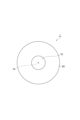
- FIG. 1 is a sectional view showing an optical fiber according to an embodiment.
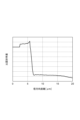
- FIG. 2 is a graph showing the refractive index distribution of the optical fiber according to the embodiment.
- FIG. 3 is a graph showing the results of organizing the relationship between refractive index distribution and transmission loss.
- FIG. 4 is a graph showing the relationship between ( ⁇ 3- ⁇ 2)/( ⁇ 1- ⁇ 2) and the root mean square of the relative refractive index difference of the core.
- FIG. 5 is a graph showing the refractive index distribution of the optical fiber according to Experimental Example 3.
- the halogen element added to the optical fiber base material not only contributes to adjusting the increase/decrease in the refractive index but also has the effect of removing impurities present inside the glass at the time of the base material. Therefore, if an attempt is made to suppress the amount of the halogen element added to zero, the transmission loss will rather worsen.
- the refractive index is highest at the center of the core and tends to decrease toward the outside in the radial direction due to desorption of the halogen element at the center of the core.
- variations in the refractive index within the core increase, resulting in the influence of structural asymmetric scattering, which worsens transmission loss.
- An object of the present disclosure is to provide an optical fiber that can reduce transmission loss.
- An optical fiber according to one aspect of the present disclosure includes a core made of silica-based glass and a cladding made of silica-based glass that surrounds the core, and the radial distance from the central axis of the core is r, and the core is made of silica-based glass.
- the radius of is a
- the maximum value ⁇ 1 of the relative refractive index difference when 0 ⁇ r/a ⁇ 0.3 and the minimum value ⁇ 2 of the relative refractive index difference when 0 ⁇ r/a ⁇ 0.9 are ⁇ 1 ⁇ ⁇ 2 ⁇ 0.02 is satisfied.
- This optical fiber can reduce transmission loss.
- the maximum value ⁇ 1, the minimum value ⁇ 2, and the maximum value ⁇ 3 of the relative refractive index difference at 0.8 ⁇ r/a ⁇ 1 are 0.5 ⁇ ( ⁇ 3 ⁇ 2)/( ⁇ 1 ⁇ 2) ⁇ 1.5 may be satisfied. In this case, transmission loss can be further reduced.
- the minimum value ⁇ 4 of the relative refractive index difference of the cladding may be ⁇ 0.6 ⁇ 4 ⁇ 0.2. In this case, transmission loss can be further reduced.
- the maximum value ⁇ 1 and the minimum value ⁇ 2 may satisfy ⁇ 1 ⁇ 2 ⁇ 0.04. In this case, transmission loss can be further reduced.
- the maximum value ⁇ 1 and the minimum value ⁇ 2 may satisfy ⁇ 1 ⁇ 2 ⁇ 0.06. In this case, transmission loss can be further reduced.
- FIG. 1 is a cross-sectional view showing an optical fiber according to an embodiment.
- the optical fiber 1 includes a core 10 extending along the central axis 1a and a cladding 20 surrounding the core 10.
- the core 10 and the cladding 20 are made of silica-based glass whose main component is silica glass, in which the mass ratio of silica glass is 90% or more.
- the core 10 contains, for example, halogen elements such as fluorine (F) and chlorine (Cl), and alkali metal elements such as lithium (Li), sodium (Na), potassium (K), and rubidium (Rb).
- the cladding 20 may contain, for example, halogen elements such as F and Cl.
- the refractive index of the core 10 is higher than the refractive index of the cladding 20.
- the effective cross-sectional area Aeff of the optical fiber 1 at a wavelength of 1550 nm is 80 ⁇ m 2 or more and 160 ⁇ m 2 or less.
- the transmission loss of the optical fiber 1 at a wavelength of 1550 nm is 0.150 dB/km or less.
- the radius a of the core 10 is, for example, 4 ⁇ m or more and 7 ⁇ m or less.
- FIG. 2 is a graph showing the refractive index distribution of the optical fiber according to the embodiment.
- the vertical axis shows the relative refractive index difference ⁇ [%] based on the refractive index of pure silica (SiO 2 ), and the horizontal axis shows the radial distance r [ ⁇ m] from the central axis 1a of the core 10.
- the position where the value d ⁇ (r)/dr obtained by differentiating the relative refractive index difference ⁇ (r) with respect to the radial distance r has the minimum value (steepest downward slope) is defined as the interface (boundary) between the core 10 and the cladding 20. be done.
- the radial distance r between the interface between the core 10 and the cladding 20 corresponds to the radius a of the core 10.
- the maximum value (local maximum value) of the relative refractive index difference is ⁇ 1 [%], and the relative refractive index difference is ⁇ 1.
- the radial distance be r1.
- the minimum radial distance is defined as r1
- the local maximum value is defined as the maximum value ⁇ 1.
- ⁇ 1 satisfies -0.1 ⁇ 1 ⁇ 0.1. 0 ⁇ r1/a ⁇ 0.1 may be satisfied.
- the minimum value (minimum value) of the relative refractive index difference is ⁇ 2 [%], and the relative refractive index difference is ⁇ 2.
- the radial distance be r2. If a plurality of minimum values exist, the minimum radial distance is defined as r2, and the minimum value is defined as the minimum value ⁇ 2. ⁇ 2 satisfies -0.2 ⁇ 2 ⁇ 0. However, ⁇ 1 ⁇ 2. 0 ⁇ r2/a ⁇ 0.5, 0 ⁇ r2/a ⁇ 0.4, and 0 ⁇ r2/a ⁇ 0.35.
- the maximum value (local maximum value) of the relative refractive index difference is ⁇ 3 [%], and the relative refractive index difference is ⁇ 3.
- the radial distance be r3.
- the maximum radial distance is defined as r3, and the local maximum value is defined as the maximum value ⁇ 3.
- ⁇ 3 satisfies -0.1 ⁇ 3 ⁇ 0.1.
- the minimum value (minimum value) of the relative refractive index difference is ⁇ 4 [%]
- the radial distance at which the relative refractive index difference is ⁇ 4 is r4. If a plurality of minimum values exist, the minimum radial distance is defined as r4, and the minimum value is defined as the minimum value ⁇ 4. ⁇ 4 may be ⁇ 0.6 ⁇ 4 ⁇ 0.2.
- the maximum value ⁇ 1 and the minimum value ⁇ 2 satisfy ⁇ 1 ⁇ 2 ⁇ 0.02. Further, the maximum value ⁇ 1, the minimum value ⁇ 2, and the maximum value ⁇ 3 satisfy 0.5 ⁇ ( ⁇ 3 ⁇ 2)/( ⁇ 1 ⁇ 2) ⁇ 1.5.
- ( ⁇ 3- ⁇ 2)/( ⁇ 1- ⁇ 2) is an index indicating the variation in the relative refractive index difference ⁇ within the core 10. The closer the maximum value ⁇ 1 at the center of the core 10 and the maximum value ⁇ 3 at the outer periphery are to each other, the closer ( ⁇ 3 ⁇ 2)/( ⁇ 1 ⁇ 2) approaches 1.
- the optical fiber 1 according to this embodiment is realized by the following means.
- the maximum value ⁇ 1 was achieved by locally depleting the halogen concentration, especially the F concentration, in the center of the core 10. Local depletion of the F concentration can be achieved, for example, by locally heating the glass portion corresponding to the center of the core 10 in the optical fiber preform after impurities have been removed in a dehydration process. This heating temperature may be 1000°C or higher, or 1400°C or higher.
- the Cl concentration and F concentration at the position of the radial distance r1 may each be 1000 wtppm or less, or 500 wtppm or less.
- the amount of halogen added is adjusted during sintering of the glass body that will become the core so that the halogen concentration at the outer periphery of the core is reduced.
- the F concentration in the cladding portion is 10,000 wtppm or more
- the halogen concentration in the outer peripheral portion of the core portion is too low, the difference in glass viscosity at the interface between the core portion and the cladding portion will become large. As a result, defects that lead to increased transmission loss are likely to occur at the interface. Therefore, at the position of the radial distance r3 corresponding to the interface position between the core 10 and the cladding 20, the halogen concentration may be 100 wtppm or more, or 500 wtppm or more.
- FIG. 3 is a graph showing the results of organizing the relationship between refractive index distribution and transmission loss.
- the transmission loss is ( ⁇ 3- ⁇ 2)/( ⁇ 1- ⁇ 2). The relationship between is plotted. Note that the value of ⁇ 1 ⁇ 2 for each optical fiber includes an error of ⁇ 0.005%.
- ⁇ 1- ⁇ 2 ⁇ 0.02 may be satisfied, and ⁇ 1- ⁇ 2 ⁇ 0.04. It can be confirmed that ⁇ 1 ⁇ 2 ⁇ 0.06 may be satisfied.
- ⁇ 1 ⁇ 2 ⁇ 0.02 a transmission loss of 0.150 dB/km or less can be achieved.
- ⁇ 1 ⁇ 2 ⁇ 0.04 a transmission loss of 0.1495 dB/km or less can be achieved.
- ⁇ 1 ⁇ 2 ⁇ 0.06 a transmission loss of 0.149 dB/km or less can be achieved.
- ⁇ 1- ⁇ 2 corresponds to the amount of decrease in the halogen concentration at the center of the core 10, and as the halogen concentration decreases, Rayleigh scattering due to concentration unevenness decreases, resulting in a reduction in transmission loss. Suggests.
- FIG. 4 is a graph showing the relationship between ( ⁇ 3 ⁇ 2)/( ⁇ 1 ⁇ 2) and the root mean square (RMS) of the relative refractive index difference of the core.
- the RMS of the relative refractive index difference of the core is the mean square variation ( ⁇ (r) - ⁇ e) of the relative refractive index difference ⁇ (r) with respect to the effective relative refractive index difference ⁇ e in the range of 0 ⁇ r ⁇ r3. It is the square root of the average value in the range r ⁇ r3.
- the mean square variation ( ⁇ (r) ⁇ e) 2 also decreases. It can be confirmed that this reduces structural asymmetric scattering and, as a result, reduces transmission loss.
- the optical fiber of Experimental Example 1 corresponds to the optical fiber 1 according to the embodiment, and has a refractive index profile in which the relative refractive index difference increases at the radial distances r1 and r3.
- the optical fiber according to Experimental Example 2 has a refractive index profile in which the relative refractive index difference is high at the radial distance r1 and the relative refractive index difference is low at the radial distance r3. As shown in FIG.
- the optical fiber according to Experimental Example 3 has a typical ring core-shaped refractive index profile in which the relative refractive index difference is high at the radial distance r3 and the relative refractive index difference is low at the radial distance r1. have. It can be said that the optical fiber according to Experimental Example 1 also has a ring core-shaped refractive index profile.
- the optical fiber according to Experimental Example 4 has a refractive index profile in which the relative refractive index difference is low at both the radial distances r1 and r3.
- Table 1 shows, for each optical fiber, ⁇ 1- ⁇ 2 [%], ⁇ 3- ⁇ 2 [%], transmission loss [dB/km] at a wavelength of 1550 nm, effective cross-sectional area Aeff [ ⁇ m 2 ] at a wavelength of 1550 nm, and Chromatic dispersion [ps/nm/km] and fiber cutoff wavelength ⁇ c [nm] are shown.
- the optical fiber of Experimental Example 1 has the lowest transmission loss. This is considered to be because the halogen concentration of the core was reduced by having a protruding refractive index profile at the center of the core due to a drop in halogen concentration. Furthermore, it can be confirmed that the optical fiber of Experimental Example 1 has almost the same characteristics as the optical fiber of Experimental Example 3 in effective cross-sectional area Aeff, wavelength dispersion, and fiber cutoff wavelength ⁇ c.
- Optical fiber 1a Central axis 10
- Core 20 ... Clad
Landscapes
- Physics & Mathematics (AREA)
- Chemical & Material Sciences (AREA)
- Optics & Photonics (AREA)
- Life Sciences & Earth Sciences (AREA)
- Engineering & Computer Science (AREA)
- Chemical Kinetics & Catalysis (AREA)
- General Chemical & Material Sciences (AREA)
- Geochemistry & Mineralogy (AREA)
- Materials Engineering (AREA)
- Organic Chemistry (AREA)
- General Physics & Mathematics (AREA)
- Glass Compositions (AREA)
Priority Applications (4)
| Application Number | Priority Date | Filing Date | Title |
|---|---|---|---|
| US18/867,075 US20250327969A1 (en) | 2022-05-26 | 2023-05-10 | Optical fiber |
| CN202380040638.5A CN119213340A (zh) | 2022-05-26 | 2023-05-10 | 光纤 |
| EP23811618.0A EP4535051A4 (en) | 2022-05-26 | 2023-05-10 | FIBER OPTICS |
| JP2024523026A JPWO2023228743A1 (https=) | 2022-05-26 | 2023-05-10 |
Applications Claiming Priority (2)
| Application Number | Priority Date | Filing Date | Title |
|---|---|---|---|
| JP2022-086237 | 2022-05-26 | ||
| JP2022086237 | 2022-05-26 |
Publications (1)
| Publication Number | Publication Date |
|---|---|
| WO2023228743A1 true WO2023228743A1 (ja) | 2023-11-30 |
Family
ID=88919106
Family Applications (1)
| Application Number | Title | Priority Date | Filing Date |
|---|---|---|---|
| PCT/JP2023/017565 Ceased WO2023228743A1 (ja) | 2022-05-26 | 2023-05-10 | 光ファイバ |
Country Status (5)
| Country | Link |
|---|---|
| US (1) | US20250327969A1 (https=) |
| EP (1) | EP4535051A4 (https=) |
| JP (1) | JPWO2023228743A1 (https=) |
| CN (1) | CN119213340A (https=) |
| WO (1) | WO2023228743A1 (https=) |
Citations (12)
| Publication number | Priority date | Publication date | Assignee | Title |
|---|---|---|---|---|
| JPH09304640A (ja) * | 1996-02-12 | 1997-11-28 | Corning Inc | 大きい実効面積を有する単一モード光導波路 |
| JP2003522337A (ja) * | 1998-07-31 | 2003-07-22 | コーニング・インコーポレーテッド | 長距離通信用シングルモード光導波路 |
| US20050013571A1 (en) * | 2003-07-18 | 2005-01-20 | Wood William A. | Large effective area, low kappa, dispersion compensating optical fiber and telecommunication span including same |
| WO2006049279A1 (ja) * | 2004-11-05 | 2006-05-11 | Fujikura Ltd. | 光ファイバ及び伝送システム並びに波長多重伝送システム |
| JP2009510528A (ja) * | 2005-10-03 | 2009-03-12 | コーニング インコーポレイテッド | 大有効面積高閾値光ファイバ |
| US7689085B1 (en) | 2009-01-30 | 2010-03-30 | Corning Incorporated | Large effective area fiber with GE-free core |
| JP2010520499A (ja) * | 2007-02-28 | 2010-06-10 | コーニング インコーポレイテッド | 第三高調波に基づく光ファイバー光源 |
| JP2013178497A (ja) * | 2012-01-30 | 2013-09-09 | Sumitomo Electric Ind Ltd | 光ファイバ、及びレーザ加工装置 |
| US20140294355A1 (en) | 2013-03-28 | 2014-10-02 | Corning Incorporated | Large effective area fiber with low bending losses |
| US20170017032A1 (en) | 2015-05-29 | 2017-01-19 | Corning Incorporated | Optical fiber with macrobend loss mitigating layer |
| JP2021043262A (ja) * | 2019-09-06 | 2021-03-18 | 株式会社フジクラ | 光ファイバ、レーザ生成装置、レーザ加工装置、及び光ファイバの製造方法 |
| JP2022086237A (ja) | 2020-11-30 | 2022-06-09 | セイコーエプソン株式会社 | 虚像表示装置 |
-
2023
- 2023-05-10 US US18/867,075 patent/US20250327969A1/en active Pending
- 2023-05-10 WO PCT/JP2023/017565 patent/WO2023228743A1/ja not_active Ceased
- 2023-05-10 JP JP2024523026A patent/JPWO2023228743A1/ja active Pending
- 2023-05-10 EP EP23811618.0A patent/EP4535051A4/en active Pending
- 2023-05-10 CN CN202380040638.5A patent/CN119213340A/zh active Pending
Patent Citations (14)
| Publication number | Priority date | Publication date | Assignee | Title |
|---|---|---|---|---|
| JPH09304640A (ja) * | 1996-02-12 | 1997-11-28 | Corning Inc | 大きい実効面積を有する単一モード光導波路 |
| JP2003522337A (ja) * | 1998-07-31 | 2003-07-22 | コーニング・インコーポレーテッド | 長距離通信用シングルモード光導波路 |
| US20050013571A1 (en) * | 2003-07-18 | 2005-01-20 | Wood William A. | Large effective area, low kappa, dispersion compensating optical fiber and telecommunication span including same |
| WO2006049279A1 (ja) * | 2004-11-05 | 2006-05-11 | Fujikura Ltd. | 光ファイバ及び伝送システム並びに波長多重伝送システム |
| JP2009510528A (ja) * | 2005-10-03 | 2009-03-12 | コーニング インコーポレイテッド | 大有効面積高閾値光ファイバ |
| JP2010520499A (ja) * | 2007-02-28 | 2010-06-10 | コーニング インコーポレイテッド | 第三高調波に基づく光ファイバー光源 |
| US7689085B1 (en) | 2009-01-30 | 2010-03-30 | Corning Incorporated | Large effective area fiber with GE-free core |
| JP2012516473A (ja) * | 2009-01-30 | 2012-07-19 | コーニング インコーポレイテッド | Ge不含有コアを有する大実効断面積ファイバ |
| JP2013178497A (ja) * | 2012-01-30 | 2013-09-09 | Sumitomo Electric Ind Ltd | 光ファイバ、及びレーザ加工装置 |
| US20140294355A1 (en) | 2013-03-28 | 2014-10-02 | Corning Incorporated | Large effective area fiber with low bending losses |
| JP2016519333A (ja) * | 2013-03-28 | 2016-06-30 | コーニング インコーポレイテッド | 低い曲げ損失を有する大きな有効面積のファイバ |
| US20170017032A1 (en) | 2015-05-29 | 2017-01-19 | Corning Incorporated | Optical fiber with macrobend loss mitigating layer |
| JP2021043262A (ja) * | 2019-09-06 | 2021-03-18 | 株式会社フジクラ | 光ファイバ、レーザ生成装置、レーザ加工装置、及び光ファイバの製造方法 |
| JP2022086237A (ja) | 2020-11-30 | 2022-06-09 | セイコーエプソン株式会社 | 虚像表示装置 |
Non-Patent Citations (2)
| Title |
|---|
| H. KAKIUCHIDA ET AL.: "Rayleigh Scattering in Fluorine-Doped Silica Glass", JOURNAL OF JAPAN APPLIED PHYSICS, vol. 42, no. 10, October 2003 (2003-10-01), pages 6516 - 6517 |
| See also references of EP4535051A4 |
Also Published As
| Publication number | Publication date |
|---|---|
| US20250327969A1 (en) | 2025-10-23 |
| EP4535051A4 (en) | 2025-08-27 |
| CN119213340A (zh) | 2024-12-27 |
| JPWO2023228743A1 (https=) | 2023-11-30 |
| EP4535051A1 (en) | 2025-04-09 |
Similar Documents
| Publication | Publication Date | Title |
|---|---|---|
| JP7190236B2 (ja) | フッ素および塩素が共ドープされたコア領域を有する低損失光ファイバ | |
| US10571628B2 (en) | Low loss optical fiber with core codoped with two or more halogens | |
| JP6527973B2 (ja) | 光ファイバ | |
| KR102034362B1 (ko) | 도핑 최적화된 최저 감쇠 단일모드 광섬유 | |
| US11714229B2 (en) | Optical fiber and method of manufacturing optical fiber | |
| WO2017020456A1 (zh) | 一种超低衰耗弯曲不敏感单模光纤 | |
| JPWO2016152507A1 (ja) | マルチコア光ファイバ | |
| JP7388353B2 (ja) | 光ファイバ | |
| CN107111055A (zh) | 光纤 | |
| WO2021082979A1 (zh) | 一种低色散单模光纤 | |
| WO2025123624A1 (zh) | 低损耗单模光纤 | |
| WO2024119527A1 (zh) | 一种弯曲不敏感高带宽多模光纤 | |
| JPWO2023157505A5 (https=) | ||
| JP7455079B2 (ja) | 光ファイバ | |
| WO2023228743A1 (ja) | 光ファイバ | |
| WO2020121915A1 (ja) | 光ファイバおよび光ファイバの製造方法 | |
| JP7813714B2 (ja) | 光ファイバ | |
| US11714228B2 (en) | Optical fiber and method of manufacturing optical fiber | |
| CN113552666B (zh) | 光纤 | |
| CN106604899B (zh) | 光纤预制棒、光纤和光纤的制造方法 | |
| JP7608438B2 (ja) | 光ファイバ | |
| WO2024048118A1 (ja) | 光ファイバ | |
| CN115576051A (zh) | 单模光纤及其应用 | |
| WO2022181614A1 (ja) | 光ファイバ | |
| JPWO2023228743A5 (https=) |
Legal Events
| Date | Code | Title | Description |
|---|---|---|---|
| 121 | Ep: the epo has been informed by wipo that ep was designated in this application |
Ref document number: 23811618 Country of ref document: EP Kind code of ref document: A1 |
|
| WWE | Wipo information: entry into national phase |
Ref document number: 2024523026 Country of ref document: JP |
|
| WWE | Wipo information: entry into national phase |
Ref document number: 202380040638.5 Country of ref document: CN |
|
| WWE | Wipo information: entry into national phase |
Ref document number: 18867075 Country of ref document: US |
|
| WWP | Wipo information: published in national office |
Ref document number: 202380040638.5 Country of ref document: CN |
|
| NENP | Non-entry into the national phase |
Ref country code: DE |
|
| WWE | Wipo information: entry into national phase |
Ref document number: 2023811618 Country of ref document: EP |
|
| ENP | Entry into the national phase |
Ref document number: 2023811618 Country of ref document: EP Effective date: 20250102 |
|
| WWP | Wipo information: published in national office |
Ref document number: 2023811618 Country of ref document: EP |
|
| WWP | Wipo information: published in national office |
Ref document number: 18867075 Country of ref document: US |