WO2023224123A1 - 重ね合わせホットスタンプ成形体の製造方法 - Google Patents
重ね合わせホットスタンプ成形体の製造方法 Download PDFInfo
- Publication number
- WO2023224123A1 WO2023224123A1 PCT/JP2023/018803 JP2023018803W WO2023224123A1 WO 2023224123 A1 WO2023224123 A1 WO 2023224123A1 JP 2023018803 W JP2023018803 W JP 2023018803W WO 2023224123 A1 WO2023224123 A1 WO 2023224123A1
- Authority
- WO
- WIPO (PCT)
- Prior art keywords
- steel plate
- plated steel
- formula
- heating
- based plated
- Prior art date
- Legal status (The legal status is an assumption and is not a legal conclusion. Google has not performed a legal analysis and makes no representation as to the accuracy of the status listed.)
- Ceased
Links
Images


Classifications
-
- B—PERFORMING OPERATIONS; TRANSPORTING
- B32—LAYERED PRODUCTS
- B32B—LAYERED PRODUCTS, i.e. PRODUCTS BUILT-UP OF STRATA OF FLAT OR NON-FLAT, e.g. CELLULAR OR HONEYCOMB, FORM
- B32B15/00—Layered products comprising a layer of metal
- B32B15/01—Layered products comprising a layer of metal all layers being exclusively metallic
- B32B15/012—Layered products comprising a layer of metal all layers being exclusively metallic one layer being formed of an iron alloy or steel, another layer being formed of aluminium or an aluminium alloy
-
- B—PERFORMING OPERATIONS; TRANSPORTING
- B21—MECHANICAL METAL-WORKING WITHOUT ESSENTIALLY REMOVING MATERIAL; PUNCHING METAL
- B21D—WORKING OR PROCESSING OF SHEET METAL OR METAL TUBES, RODS OR PROFILES WITHOUT ESSENTIALLY REMOVING MATERIAL; PUNCHING METAL
- B21D22/00—Shaping without cutting, by stamping, spinning, or deep-drawing
- B21D22/02—Stamping using rigid devices or tools
- B21D22/022—Stamping using rigid devices or tools by heating the blank or stamping associated with heat treatment
-
- B—PERFORMING OPERATIONS; TRANSPORTING
- B21—MECHANICAL METAL-WORKING WITHOUT ESSENTIALLY REMOVING MATERIAL; PUNCHING METAL
- B21D—WORKING OR PROCESSING OF SHEET METAL OR METAL TUBES, RODS OR PROFILES WITHOUT ESSENTIALLY REMOVING MATERIAL; PUNCHING METAL
- B21D24/00—Special deep-drawing arrangements in, or in connection with, presses
-
- C—CHEMISTRY; METALLURGY
- C09—DYES; PAINTS; POLISHES; NATURAL RESINS; ADHESIVES; COMPOSITIONS NOT OTHERWISE PROVIDED FOR; APPLICATIONS OF MATERIALS NOT OTHERWISE PROVIDED FOR
- C09D—COATING COMPOSITIONS, e.g. PAINTS, VARNISHES OR LACQUERS; FILLING PASTES; CHEMICAL PAINT OR INK REMOVERS; INKS; CORRECTING FLUIDS; WOODSTAINS; PASTES OR SOLIDS FOR COLOURING OR PRINTING; USE OF MATERIALS THEREFOR
- C09D7/00—Features of coating compositions, not provided for in group C09D5/00; Processes for incorporating ingredients in coating compositions
- C09D7/40—Additives
- C09D7/60—Additives non-macromolecular
- C09D7/61—Additives non-macromolecular inorganic
-
- C—CHEMISTRY; METALLURGY
- C21—METALLURGY OF IRON
- C21D—MODIFYING THE PHYSICAL STRUCTURE OF FERROUS METALS; GENERAL DEVICES FOR HEAT TREATMENT OF FERROUS OR NON-FERROUS METALS OR ALLOYS; MAKING METAL MALLEABLE, e.g. BY DECARBURISATION OR TEMPERING
- C21D1/00—General methods or devices for heat treatment, e.g. annealing, hardening, quenching or tempering
- C21D1/18—Hardening; Quenching with or without subsequent tempering
-
- C—CHEMISTRY; METALLURGY
- C21—METALLURGY OF IRON
- C21D—MODIFYING THE PHYSICAL STRUCTURE OF FERROUS METALS; GENERAL DEVICES FOR HEAT TREATMENT OF FERROUS OR NON-FERROUS METALS OR ALLOYS; MAKING METAL MALLEABLE, e.g. BY DECARBURISATION OR TEMPERING
- C21D1/00—General methods or devices for heat treatment, e.g. annealing, hardening, quenching or tempering
- C21D1/68—Temporary coatings or embedding materials applied before or during heat treatment
- C21D1/70—Temporary coatings or embedding materials applied before or during heat treatment while heating or quenching
-
- C—CHEMISTRY; METALLURGY
- C21—METALLURGY OF IRON
- C21D—MODIFYING THE PHYSICAL STRUCTURE OF FERROUS METALS; GENERAL DEVICES FOR HEAT TREATMENT OF FERROUS OR NON-FERROUS METALS OR ALLOYS; MAKING METAL MALLEABLE, e.g. BY DECARBURISATION OR TEMPERING
- C21D8/00—Modifying the physical properties of ferrous metals or ferrous alloys by deformation combined with, or followed by, heat treatment
-
- C—CHEMISTRY; METALLURGY
- C21—METALLURGY OF IRON
- C21D—MODIFYING THE PHYSICAL STRUCTURE OF FERROUS METALS; GENERAL DEVICES FOR HEAT TREATMENT OF FERROUS OR NON-FERROUS METALS OR ALLOYS; MAKING METAL MALLEABLE, e.g. BY DECARBURISATION OR TEMPERING
- C21D9/00—Heat treatment, e.g. annealing, hardening, quenching or tempering, adapted for particular articles; Furnaces therefor
- C21D9/0068—Heat treatment, e.g. annealing, hardening, quenching or tempering, adapted for particular articles; Furnaces therefor for particular articles not mentioned below
-
- C—CHEMISTRY; METALLURGY
- C21—METALLURGY OF IRON
- C21D—MODIFYING THE PHYSICAL STRUCTURE OF FERROUS METALS; GENERAL DEVICES FOR HEAT TREATMENT OF FERROUS OR NON-FERROUS METALS OR ALLOYS; MAKING METAL MALLEABLE, e.g. BY DECARBURISATION OR TEMPERING
- C21D9/00—Heat treatment, e.g. annealing, hardening, quenching or tempering, adapted for particular articles; Furnaces therefor
- C21D9/46—Heat treatment, e.g. annealing, hardening, quenching or tempering, adapted for particular articles; Furnaces therefor for sheet metals
- C21D9/48—Heat treatment, e.g. annealing, hardening, quenching or tempering, adapted for particular articles; Furnaces therefor for sheet metals deep-drawing sheets
-
- C—CHEMISTRY; METALLURGY
- C22—METALLURGY; FERROUS OR NON-FERROUS ALLOYS; TREATMENT OF ALLOYS OR NON-FERROUS METALS
- C22C—ALLOYS
- C22C21/00—Alloys based on aluminium
- C22C21/02—Alloys based on aluminium with silicon as the next major constituent
-
- C—CHEMISTRY; METALLURGY
- C22—METALLURGY; FERROUS OR NON-FERROUS ALLOYS; TREATMENT OF ALLOYS OR NON-FERROUS METALS
- C22C—ALLOYS
- C22C38/00—Ferrous alloys, e.g. steel alloys
- C22C38/60—Ferrous alloys, e.g. steel alloys containing lead, selenium, tellurium, or antimony, or more than 0.04% by weight of sulfur
-
- C—CHEMISTRY; METALLURGY
- C23—COATING METALLIC MATERIAL; COATING MATERIAL WITH METALLIC MATERIAL; CHEMICAL SURFACE TREATMENT; DIFFUSION TREATMENT OF METALLIC MATERIAL; COATING BY VACUUM EVAPORATION, BY SPUTTERING, BY ION IMPLANTATION OR BY CHEMICAL VAPOUR DEPOSITION, IN GENERAL; INHIBITING CORROSION OF METALLIC MATERIAL OR INCRUSTATION IN GENERAL
- C23C—COATING METALLIC MATERIAL; COATING MATERIAL WITH METALLIC MATERIAL; SURFACE TREATMENT OF METALLIC MATERIAL BY DIFFUSION INTO THE SURFACE, BY CHEMICAL CONVERSION OR SUBSTITUTION; COATING BY VACUUM EVAPORATION, BY SPUTTERING, BY ION IMPLANTATION OR BY CHEMICAL VAPOUR DEPOSITION, IN GENERAL
- C23C2/00—Hot-dipping or immersion processes for applying the coating material in the molten state without affecting the shape; Apparatus therefor
- C23C2/04—Hot-dipping or immersion processes for applying the coating material in the molten state without affecting the shape; Apparatus therefor characterised by the coating material
- C23C2/12—Aluminium or alloys based thereon
-
- C—CHEMISTRY; METALLURGY
- C23—COATING METALLIC MATERIAL; COATING MATERIAL WITH METALLIC MATERIAL; CHEMICAL SURFACE TREATMENT; DIFFUSION TREATMENT OF METALLIC MATERIAL; COATING BY VACUUM EVAPORATION, BY SPUTTERING, BY ION IMPLANTATION OR BY CHEMICAL VAPOUR DEPOSITION, IN GENERAL; INHIBITING CORROSION OF METALLIC MATERIAL OR INCRUSTATION IN GENERAL
- C23C—COATING METALLIC MATERIAL; COATING MATERIAL WITH METALLIC MATERIAL; SURFACE TREATMENT OF METALLIC MATERIAL BY DIFFUSION INTO THE SURFACE, BY CHEMICAL CONVERSION OR SUBSTITUTION; COATING BY VACUUM EVAPORATION, BY SPUTTERING, BY ION IMPLANTATION OR BY CHEMICAL VAPOUR DEPOSITION, IN GENERAL
- C23C2/00—Hot-dipping or immersion processes for applying the coating material in the molten state without affecting the shape; Apparatus therefor
- C23C2/26—After-treatment
-
- C—CHEMISTRY; METALLURGY
- C23—COATING METALLIC MATERIAL; COATING MATERIAL WITH METALLIC MATERIAL; CHEMICAL SURFACE TREATMENT; DIFFUSION TREATMENT OF METALLIC MATERIAL; COATING BY VACUUM EVAPORATION, BY SPUTTERING, BY ION IMPLANTATION OR BY CHEMICAL VAPOUR DEPOSITION, IN GENERAL; INHIBITING CORROSION OF METALLIC MATERIAL OR INCRUSTATION IN GENERAL
- C23C—COATING METALLIC MATERIAL; COATING MATERIAL WITH METALLIC MATERIAL; SURFACE TREATMENT OF METALLIC MATERIAL BY DIFFUSION INTO THE SURFACE, BY CHEMICAL CONVERSION OR SUBSTITUTION; COATING BY VACUUM EVAPORATION, BY SPUTTERING, BY ION IMPLANTATION OR BY CHEMICAL VAPOUR DEPOSITION, IN GENERAL
- C23C2/00—Hot-dipping or immersion processes for applying the coating material in the molten state without affecting the shape; Apparatus therefor
- C23C2/34—Hot-dipping or immersion processes for applying the coating material in the molten state without affecting the shape; Apparatus therefor characterised by the shape of the material to be treated
- C23C2/36—Elongated material
- C23C2/40—Plates; Strips
-
- B—PERFORMING OPERATIONS; TRANSPORTING
- B21—MECHANICAL METAL-WORKING WITHOUT ESSENTIALLY REMOVING MATERIAL; PUNCHING METAL
- B21D—WORKING OR PROCESSING OF SHEET METAL OR METAL TUBES, RODS OR PROFILES WITHOUT ESSENTIALLY REMOVING MATERIAL; PUNCHING METAL
- B21D35/00—Combined processes according to or processes combined with methods covered by groups B21D1/00 - B21D31/00
- B21D35/002—Processes combined with methods covered by groups B21D1/00 - B21D31/00
- B21D35/005—Processes combined with methods covered by groups B21D1/00 - B21D31/00 characterized by the material of the blank or the workpiece
- B21D35/007—Layered blanks
-
- C—CHEMISTRY; METALLURGY
- C08—ORGANIC MACROMOLECULAR COMPOUNDS; THEIR PREPARATION OR CHEMICAL WORKING-UP; COMPOSITIONS BASED THEREON
- C08K—Use of inorganic or non-macromolecular organic substances as compounding ingredients
- C08K3/00—Use of inorganic substances as compounding ingredients
- C08K3/02—Elements
- C08K3/04—Carbon
-
- C—CHEMISTRY; METALLURGY
- C21—METALLURGY OF IRON
- C21D—MODIFYING THE PHYSICAL STRUCTURE OF FERROUS METALS; GENERAL DEVICES FOR HEAT TREATMENT OF FERROUS OR NON-FERROUS METALS OR ALLOYS; MAKING METAL MALLEABLE, e.g. BY DECARBURISATION OR TEMPERING
- C21D1/00—General methods or devices for heat treatment, e.g. annealing, hardening, quenching or tempering
- C21D1/62—Quenching devices
- C21D1/673—Quenching devices for die quenching
-
- C—CHEMISTRY; METALLURGY
- C21—METALLURGY OF IRON
- C21D—MODIFYING THE PHYSICAL STRUCTURE OF FERROUS METALS; GENERAL DEVICES FOR HEAT TREATMENT OF FERROUS OR NON-FERROUS METALS OR ALLOYS; MAKING METAL MALLEABLE, e.g. BY DECARBURISATION OR TEMPERING
- C21D2221/00—Treating localised areas of an article
-
- C—CHEMISTRY; METALLURGY
- C21—METALLURGY OF IRON
- C21D—MODIFYING THE PHYSICAL STRUCTURE OF FERROUS METALS; GENERAL DEVICES FOR HEAT TREATMENT OF FERROUS OR NON-FERROUS METALS OR ALLOYS; MAKING METAL MALLEABLE, e.g. BY DECARBURISATION OR TEMPERING
- C21D2251/00—Treating composite or clad material
- C21D2251/04—Welded or brazed overlays
Definitions
- the present invention relates to a method for manufacturing a laminated hot-stamped molded body.
- TRIP Transformation Induced Plasticity
- hot stamping also called hot press, hot press, die quench, press quench, etc.
- This hot stamping ensures formability by hot pressing the steel plate immediately after heating it to Ac3 point or higher (for example, 800°C or higher) and turning it into austenite.
- This is a method for manufacturing parts that obtains a desired high-strength material after pressing by rapidly cooling the material to a temperature below (for example, below 400°C) to turn the material into martensite and hardening it. According to this method, it is possible to obtain automobile parts that have excellent shape fixability after molding.
- the various press-formed bodies used for the parts that make up automobile bodies have various performances and characteristics from various viewpoints such as static strength, dynamic strength, collision safety, and even weight reduction. Improvement is required.
- automobile parts such as A-pillar reinforcement, B-pillar reinforcement, bumper reinforcement, tunnel reinforcement, side sill reinforcement, roof reinforcement, or floor cross member
- only specific parts of each automobile part can be It is required to have better collision resistance than general parts except for parts.
- a problem peculiar to the use of non-plated steel sheets as the material for the overlapping blank is that although the unoverlapped portion (hereinafter also referred to as the "single section") can be shot blasted, the overlapping Oxidized scale formed between steel plates in a portion (hereinafter also referred to as an "overlapping portion") is difficult to remove by shot blasting, and there is a problem in that corrosion resistance is particularly likely to deteriorate.
- Plated steel sheets used for hot pressing generally include Zn-based plated steel sheets and Al-based plated steel sheets.
- Zn-based plating and Al-based plating due to the alloying reaction in which Fe diffuses into the plating, after hot stamp heating, Zn-based plating becomes Zn-Fe-based plating, and Al-based plating becomes Al-Fe-based plating. Become.
- Zn-based plated steel sheet that is, plated steel sheet containing 50% by mass or more of Zn (Zn plating, or Zn-Fe alloy, Zn-Ni alloy, Zn-Fe-Al Zn-based alloy plating such as alloy) suppresses the formation of oxide scale and eliminates the problem of requiring shot blasting.
- Zn-based plated steel sheets are used as the overlapping blank material and the overlapping portion is bent during hot stamping, cracks may occur in the base steel, causing problems in collision resistance. This is because when zinc, which has a relatively low melting point, remains, Zn becomes a liquid metal and invades the base steel from the plating surface, resulting in a problem called liquid metal embrittlement.
- bending is a means of ensuring collision resistance properties from the aspect of shape, and bending the overlapping portion is an extremely important method of utilizing the overlapping molded body.
- Patent Document 2 and Patent Document 3 as a countermeasure against liquid metal embrittlement that is taken when using a Zn-based plated steel sheet as a hot stamp, generally a Zn-Fe alloying reaction is promoted during hot stamp heating.
- Countermeasures include increasing the melting point of the plating using hot stamping, and lowering the forming temperature during hot stamp bending and waiting for the zinc to solidify.
- a particular problem when using zinc-based plated steel sheets as the material for the stacked blank is that the thickness of the stacked part is thicker than that of the other sheets, so the temperature rise rate is slow, and the Zn-Fe alloy is heated during hot stamping. There is a problem in that it is difficult to advance the chemical reaction.
- Al-based plated steel sheet as shown in Patent Document 4 i.e., a plated steel plate containing 50% by mass or more of Al (Al plating or Al-based alloy plating such as Al-Si alloy or Al-Fe-Si alloy)
- Al Al plating or Al-based alloy plating such as Al-Si alloy or Al-Fe-Si alloy
- Al-based plated steel sheets are suitable for use as a material for overlapping blanks.
- the Al--Fe alloying reaction of the plating of the Al-based plated steel sheet which progresses by heating with hot stamping, is important for the spot weldability of the plating.
- the heating time of hot stamping is increased, one part of the steel sheet is heated for an excessive time, so the Al-Fe alloying reaction progresses and an Al-Fe alloy plating layer with a high Fe concentration is formed. It ends up.
- spot weldability deteriorates in a single steel plate portion.
- an Al-based plated steel sheet is suitable for use as a material for hot stamping lamination blanks.
- hot stamping the problem of part productivity and spot weldability of one piece can be solved by an invention that improves both the slow heating rate of the overlapping part and the excessive heating of one piece. It is hoped that it will be resolved.
- heating during hot stamping is performed by controlling the heating time. More specifically, for example, in a preliminary test, the temperature increase rate or temperature increase time of the overlapping portion was confirmed. Then, after taking into account variations in the obtained knowledge regarding the temperature increase rate or temperature increase time, heating during hot stamping is performed by taking into account a relatively long holding time, such as 10 minutes. was. Even in such cases, there is still room for improvement regarding the problem of spot weldability of a single piece as described above.
- the present invention has been made in view of the above problems, and an object of the present invention is to reduce the temperature increase rate of the overlapped portion when Al-based plated steel sheets are used as the material, It is an object of the present invention to provide a method for manufacturing a laminated hot-stamped molded article, which can improve both the problem of one sheet being heated for an excessive period of time.
- the present inventors conducted intensive research and focused on the lightness L * defined in JIS Z 8781-4:2013 of the surface of an Al-based plated steel sheet. It was found that the heating rate of hot stamping a steel plate increases. This is considered to be because the lower the brightness value, the more black the surface of the Al-based plated steel sheet is, which means that it has the property of easily absorbing heat.
- the plate thickness i.e., the total thickness of two steel plates
- the brightness of the one sheet should be increased to make it difficult to absorb heat and increase the temperature during hot stamping. It is important to slow down.
- high brightness can be obtained due to the surface having a silvery white metallic luster.
- the brightness can be lowered by using a carbon-based black film on the upper layer of the Al-based plated steel sheet.
- the carbon-based black film is burnt out by combustion due to oxidation reaction during heating of the hot stamp, it is possible to suppress the deterioration of spot weldability of laminated hot-stamped parts due to the remaining carbon-based black film. I found out.
- a first Al-based plated steel plate having a plate thickness d1 which is overlapped and welded on the first Al-based plated steel plate, and has a smaller area than the first Al-based plated steel plate, and the a second Al-based plated steel plate having a plate thickness of d2 and having a carbon-based black coating on the surface of the Al-based plated steel plate on the side not in contact with the first Al-based plated steel plate; , a heating method of heating in a heating furnace at a temperature T1, wherein the overlapping blank for hot stamping satisfies the following formulas (a) to (c), the heating time is t1 or more, and t2+ ⁇ t2
- the method of heating stacked blanks for hot stamping is as follows.
- T1 is the temperature of the heating furnace
- t1 is the smaller value of the solutions to the quadratic equation in equation (d) below
- t2 is the smaller value among the solutions to the quadratic equation in equation (e) below.
- ⁇ t2 is the following formula (f), the units of d, d1, and d2 are mm, the unit of T1 is °C, and the unit of t1, t2, and ⁇ t2 is minutes.
- ⁇ t2' is the following formula (f'), and its unit is minutes.
- ⁇ t2' 1.498 ⁇ 10 13 ⁇ e (-0.03198 ⁇ T1) ...Formula (f')
- a first Al-based plated steel plate having a plate thickness d1 which is overlapped and welded on the first Al-based plated steel plate, and has a smaller area than the first Al-based plated steel plate, and the a second Al-based plated steel plate having a plate thickness of d2 and having a carbon-based black coating on the surface layer of the Al-based plated steel plate on the side not in contact with the first Al-based plated steel plate; , a heating method of heating in a heating furnace at a temperature T3, wherein the first Al-based plated steel sheet has a carbon-based black coating on the surface of the side not in contact with the second Al-based plated steel sheet, and the A method for heating a stacked blank for hot stamping, wherein the stacked blank for hot stamping satisfie
- T3 is the temperature of the heating furnace
- t3 is the smaller value of the solutions to the quadratic equation of equation (D) below
- t4 is the smaller of the solutions of the quadratic equation of equation (E) below.
- ⁇ t4 is the following formula (F), the units of d, d1, and d2 are mm, the units of T3 are °C, and the units of t3, t4, and ⁇ t4 are minutes.
- FIG. 2 is an explanatory diagram schematically showing an example of a method for manufacturing a laminated hot stamp molded body for obtaining a laminated hot stamp molded body using a hot stamp laminated blank according to an embodiment of the present invention.
- FIG. 2 is an explanatory diagram schematically showing the structure of an Al-based plated steel plate having an Al-based plated layer on the surface of a base steel plate of the overlapping blank for hot stamping according to the same embodiment.
- FIG. 7 is a diagram showing a comparative example in which the plate temperatures of the overlapped portion and the single sheet portion were actually measured when overlap spot welding was performed and hot stamp heating was performed.
- the first steel plate is an Al-based plated steel plate, and the area is larger than that of the first steel plate having a carbon-based black film on the upper layer of the Al-based plated steel plate.
- FIG. 7 is a diagram showing an example of the invention in which the plate temperatures of the overlapped portion and the single sheet portion were actually measured when a small second steel plate was overlapped and spot welded and heated by hot stamping.
- FIG. 7 is a diagram showing the relationship between the heating temperature T1 and the heating times t1, t2+ ⁇ t2, and t2+ ⁇ t2' in the method for manufacturing a laminated hot-stamped molded body according to the same embodiment.
- the laminated hot-stamped molded article according to the embodiment has an Al-Fe alloy plating layer on the surface of the base steel plate, and a diffusion layer included in the Al-Fe alloy plating layer and in contact with the steel plate base material.
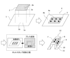
- FIG. 1 is an explanatory diagram schematically showing an example of a method for manufacturing a laminated hot-stamped molded body according to an embodiment of the present invention.
- a hot-stamped laminated blank is used as a material for the laminated hot-stamped molded body.
- the overlapping blank for hot stamping according to this embodiment is a type of tailored blank, and is also called a patchwork blank.
- a hot-stamping laminated blank 4 includes a first Al-based plated steel plate 1 and a first Al-based plated steel plate 1. It is constructed by welding 3 a second Al-based plated steel plate 2 which has a smaller area than the plated steel plate.
- the part where the second Al-based plated steel plates 2 are stacked is called a stacked part 4a, and the part where they are not stacked is called a one-piece part 4b.
- the second Al-based plated steel plate 2 is different from the first one as schematically shown in FIG. It is preferable that the first Al-based plated steel sheet 1 is disposed inside the outer edge of the first Al-based plated steel sheet 1 so that there is no protruding portion from the Al-based plated steel sheet 1 .
- the surface of the first Al-based plated steel sheet 1 has a surface 1a that is in contact with the second Al-based plated steel sheet 2, and a surface 1b that is not in contact with the second Al-based plated steel sheet 2.
- an Al-based plating layer is applied, and similarly, the second Al-based plated steel sheet 2 has a surface 2a in contact with the first Al-based plated steel sheet 1 and a surface 2a in contact with the first Al-based plated steel sheet 1.
- An Al-based plating layer is applied to both sides of the side 2b that is not covered.
- an upper layer of the Al-based plating layer is provided on the side 2b of the second Al-based plated steel sheet that is not in contact with the first Al-based plated steel sheet.
- a carbon-based black film (not shown) is provided on the surface.
- the surface of the first Al-based plated steel sheet 1 has a surface 1a on the side that is in contact with the second Al-based plated steel sheet 2
- An Al-based plating layer is applied to both sides of the surface 1b that is not in contact with the second Al-based plated steel plate 2
- the second Al-based plated steel plate 2 is similarly coated with the first Al-based plated steel plate.
- An Al-based plating layer is applied to both the surface 2a that is in contact with the first Al-based plated steel sheet 1 and the surface 2b that is not in contact with the first Al-based plated steel sheet 1.
- a carbon-based black film (not shown) is provided on the upper layer of the Al-based plating layer. Also, on the side 1b of the first Al-based plated steel sheet that is not in contact with the second Al-based plated steel plate, a carbon-based black film (not shown) is provided on the upper layer of the Al-based plating layer.
- the hot stamping stacked blank 4 is heated in a heating furnace 5 to an Ac point of 3 or more, so that the steel plate is austenitized, and the steel plate is heated immediately after being taken out from the furnace.
- the steel plate undergoes martensitic transformation by being press-formed in the mold 6 and rapidly cooled.
- the stacked hot stamping blank 4 becomes the stacked hot stamped molded body 12 according to the present embodiment, which has excellent collision resistance.
- the existence of a portion that will become the bent portion 8 when the superposed hot stamped molded product 12 is formed is present in at least a part of the overlapped portion 4a, which improves the collision characteristics of the parts of the hot stamped molded product. Preferable from this point of view.
- FIG. 1 shows a molded product using a hat-shaped mold as an example of the superimposed hot stamp molded product 12, and the parts of the hot stamp molded product 12 are named as the top part 7, the bent part of the top part, and section 8, vertical wall section 10, flange section 11, and bent section 9 of the flange section.
- the second Al-based plated steel plate 2 according to the present embodiment is arranged on the outer side of the crown part 7, but the second Al-based plated steel plate 2 is arranged inside the crown part 7.
- the object of the present invention can also be achieved by doing so.
- the stacked blank 4 for hot stamping includes the first Al-based plated steel plate 1 and the first Al-based plated steel plate 1 welded to the first Al-based plated steel plate 1.
- a second Al-based plated steel plate 2 having a smaller area, and Al-based plating is applied to both surfaces of each of the first Al-based plated steel plate 1 and the second Al-based plated steel plate 2.
- the first Al-based plated steel sheet 1 and the second Al-based plated steel sheet 2 according to the present embodiment are Al-based plated steel sheets that have Al-based plating layers on both surfaces of the base steel plate.
- the chemical composition of the base steel plate in each of the first Al-based plated steel plate 1 and the second Al-based plated steel plate 2 is not particularly limited. However, for example, in order to obtain a tensile strength of 1500 MPa or more (Vickers hardness (i.e.
- the chemical composition is , in mass%, C: 0.19 to 0.50%, Si: 0.01 to 1.50%, Mn: 0.4 to 2.0%, Cr: 0.01 to 1.00%, Ti : 0.001 to 0.100%, B: 0.0005 to 0.0100%, P: 0.100% or less, S: 0.100% or less, Al: 0 to 1.000%, N: 0 to 0.0100%, Nb: 0 to 0.100%, Mo, Ni, Cu, Co, W, Sn, V, Sb: 0 to 0.500%, respectively, Mg, Ca, Zr, REM, O: each , 0 to 0.0100%, the balance being Fe and impurities.
- the chemical composition of the base steel plate of the first Al-based plated steel plate 1 and the chemical composition of the base steel plate of the second Al-based plated steel plate 2 are the same. They may be
- the method for producing an Al-based plated steel sheet using the above chemical composition as a base material steel sheet is not particularly limited.
- a material manufactured through a conventional iron-making process and steel-making process hot rolling, pickling, cold rolling, and Sendzimir hot-dip aluminizing.
- the plate thickness d1 (mm) of the first Al-based plated steel plate 1 and the plate thickness d2 (mm) of the second Al-based plated steel plate 2 are selectively set to 0.5 mm or more, respectively. It is preferably 2 mm or less.
- the plate thickness By setting the plate thickness to 0.5 mm or more, it becomes possible to maintain the productivity of the hot rolling and cold rolling processes at a desired level.
- the plate thickness by setting the plate thickness to 3.2 mm or less, it is possible to prevent the phenomenon in which the desired tensile strength cannot be obtained due to a decrease in the cooling rate during hot stamping mold hardening, resulting in insufficient hardenability. becomes possible.
- the plate thickness d1 of the first Al-based plated steel plate 1 and the plate thickness d2 of the second Al-based plated steel plate 2 can be measured using, for example, a micrometer compliant with JIS B7502:2016.
- the plate thicknesses d1 and d2 mentioned above include the thickness of the Al-based plating layer provided on both sides in addition to the plate thickness of the base steel plate.
- An increase in the total plate thickness slows down the rate of temperature rise in the overlapping portion, reducing productivity during hot stamp heating. Therefore, the total plate thickness d is set to 4.8 mm or less. That is, d satisfies the following formula (c). 2.5 ⁇ d ⁇ 4.8... Formula (c)
- the total plate thickness d is preferably 4.6 mm or less, more preferably 4.4 mm or less, 4.2 mm or less, or 4.0 mm or less.
- the total plate thickness d is set to 2.5 mm or more.
- the total plate thickness d is preferably 2.8 mm or more, more preferably 3.2 mm or more.
- the amount of the Al-based plating layer applied to both surfaces of the first Al-based plated steel sheet 1 is W1a (g/m 2 ) on the surface 1a in contact with the second Al-based plated steel sheet 2; On the surface 1b on the side not in contact with the second Al-based plated steel plate 2, W1b (g/m 2 ). Further, the amount of adhesion of the Al-based plating layer applied to both surfaces of the second Al-based plated steel sheet 2 is W2b (g/m 2 ) on the surface 2b on the side not in contact with the first Al-based plated steel sheet 1. be.
- the values of W1a, W1b, and W2b are each independently within the range of 20 g/m 2 or more and 120 g/m 2 or less per side.
- the average adhesion amount of the Al-based plating layer on the non-overlaid portion (single-sheet portion 4b) of the overlapping blank 4 for hot stamping is defined as W1 (g/m 2 ) per side.
- W1a the adhesion amount of the Al-based plating layer on one side of the surface in contact with the second Al-based plated steel sheet 2
- W1b the adhesion amount of the Al-based plating layer on one side of the surface not in contact with the system-plated steel sheet 2
- W1 0.5 ⁇ (W1a+W1b).
- the average amount of Al-based plating layer deposited on the overlapping portion 4a of the overlapping blank 4 for hot stamping is defined as W2 (g/m 2 ) per side.
- the adhesion amount of the Al-based plating layer on one side of the surface 1b of the first Al-based plated steel sheet 1 that is not in contact with the second Al-based plated steel sheet 2 is W1b (g/m 2 )
- W2b 0.5 ⁇ (W1b+W2b).
- the surface 1a on the side that is in contact with the second Al-based plated steel sheet 2 the surface 1b on the side that is not in contact with the second Al-based plated steel sheet 2, and the second Al-based plated steel sheet 1.
- the surface 2b on the side not in contact with the first Al-based plated steel plate 1 is a surface exposed to a heat source when the manufactured stacked blanks are heated in the hot stamp. This is an important surface in controlling the rate of temperature increase.
- the amount of plating deposited on the Al-based plating layer according to this embodiment is not particularly limited.
- the properties required for hot stamped products are (a) suppression of Fe scale generation during hot stamping, and (b) prevention of plating caused by sliding off of the plating (also called powdering) during hot stamping.
- Preferable characteristics include suppressing chips and scratches.
- Powdering occurs due to compressive stress applied to the plating on the inner surface of a bent part that occurs during molding, and shear stress applied to the plating due to sliding from the mold during molding. If the adhesion amounts W1 and W2 of the Al-based plating layer on each steel plate are less than 20 g/m 2 , the thickness of the plating becomes thin, causing a problem in which Fe scale is insufficiently suppressed. Therefore, it is preferable that the adhesion amounts W1 and W2 of the Al-based plating layer on each steel plate are independently 20 g/m 2 or more.
- the adhesion amounts W1 and W2 of the Al-based plating layer on each steel plate are each independently more preferably 30 g/m 2 or more, and still more preferably, in order of preference, 35 g/m 2 or more, 40 g/m 2 or more, It is 45 g/m 2 or more, and 50 g/m 2 or more.
- the coating amounts W1 and W2 of the plating per side of each steel plate are each independently 120 g/m 2 or less.
- the amount of coating W1 and W2 per one side of each steel plate is independently more preferably 110 g/m 2 or less, and still more preferably 100 g/m 2 or less, 95 g/m 2 or less, and 90 g. / m2 or less. Note that, in the second Al-based plated steel sheet, the amount of the Al-based plating layer deposited on the surface of the second Al-based plated steel sheet in contact with the first Al-based plated steel sheet is not particularly specified.
- between the coating amounts W1 and W2 of the plating per side of each steel plate is 40 g/m 2 or less.
- is more preferably 35 g/m 2 or less, 30 g/m 2 or less, 25 g/m 2 or less, or 20 g/m 2 or less.
- the thickness ( ⁇ m) of the Al-based plating layer on each steel plate can be roughly estimated from the coating weight (g/m 2 ), and although it depends on the chemical composition of the Al-based plating layer, it can be roughly calculated by the following formula ( 1).
- FIG. 2 schematically shows the layer structure on one side of the Al-based plated steel sheet 13 in which the Al-based plated layer according to the present embodiment is provided on the surface of the base steel sheet.
- Al-based plating layer according to the present embodiment is manufactured by a hot-dip plating method, an aluminum-iron-based (Al-Fe-based) alloy layer ( ) is formed.
- the hot-dip plating method which is a common method for applying Al-based plating to a base steel plate
- the amount of adhesion is adjusted by immersing the base steel plate in a hot-dip aluminum plating bath and wiping with gas such as nitrogen or air. It is possible to produce an Al-based plated steel sheet.
- an aluminum-iron alloy layer is inevitably formed at the interface between the Al-based plating layer 14 and the base steel plate 15 in FIG. 2 due to the elution of Fe during hot-dip plating.
- the Al-based plating layer 14 in FIG. 2 also includes an aluminum-iron alloy layer.
- the chemical composition of the hot-dip aluminum plating bath for forming the Al-based plating layer (that is, the chemical composition is substantially the same as the Al-based plating layer 14 except for Fe) is not particularly limited.
- the content of Al in the hot-dip aluminizing bath is preferably 80% by mass or more in terms of excellent heat resistance required during hot stamp heating.
- the Si content of the hot-dip aluminizing bath is preferably 2% by mass or more. By setting the Si content to 2% by mass or more, it is possible to prevent the aluminum-iron alloy layer from becoming too thick and reducing formability.
- the Si content of the hot-dip aluminizing bath to 15% by mass or less, it is possible to prevent the alloying reaction during hot stamp heating from slowing down and reducing hot stamp productivity. .
- the hot-dip aluminizing bath contains 2% by mass or more and 15% by mass or less of Si
- a eutectic structure of Al and Si is formed in the Al-based plating layer 14 formed using such a plating bath based on the phase diagram. be done.
- Fe may inevitably be contained as a component eluted from the base steel sheet in an amount of 1% by mass or more and 5% by mass or less.
- Other unavoidable impurities include Cr, Mn, Zn, V, Ti, Sn, Ni, Cu, W, Bi, Mg, Ca, etc. caused by eluted components from hot-dip plating equipment and impurities in ingots from hot-dip aluminizing baths. These elements may be contained in an amount of less than 1% by mass.
- the chemical composition (average chemical composition) of the Al-based plating layer 14 according to the present embodiment is, in mass %, Al: 80 to 97%, Si: 2 to 15%, Fe: 1 to 15%, Cr: 0. % or more and less than 1%, Mo: 0% or more and less than 1%, Zn: 0% or more and less than 1%, V: 0% or more and less than 1%, Ti: 0% or more and less than 1%, Sn: 0% or more and less than 1%.
- the plating layer may contain less than 1% of the content, with the remainder being impurities.
- the hot-dip aluminizing bath inevitably contains Fe in an amount of 1% by mass or more and 5% by mass or less, whereas an aluminum-iron alloy layer is formed in the Al-based plating layer. , the proportion of Fe increases. Therefore, the chemical composition of the Al-based plating layer 14 may be Fe: 1 to 15%.
- the metal structures of the aluminum-iron alloy layer include ⁇ phase (FeAl 3 ), ⁇ phase (Fe 2 Al 5 ), ⁇ phase (FeAl 2 ), Fe 3 Al, and FeAl 2 which are binary alloys of Al and Fe. , Al solid solution BCC phase ( ⁇ 2, ⁇ ), and the combination of these plating phases constitutes an aluminum-iron alloy layer.
- the metal structures of the aluminum-iron alloy layer containing Si include ⁇ 1 phase (Al 2 Fe 3 Si 3 ), ⁇ 2 phase (Al 3 FeSi), ⁇ 3 phase (Al 2 FeSi), and ⁇ 4 phase (Al 3 FeSi 2 ), ⁇ 5 phase (Al 8 Fe 2 Si), ⁇ 6 phase (Al 9 Fe 2 Si 2 ), ⁇ 7 phase (Al 3 Fe 2 Si 3 ), ⁇ 8 phase (Al 2 Fe 3 Si 4 ), ⁇ 10 phase ( (Al 4 Fe 1.7 Si), ⁇ 11 phase (Al 5 Fe 2 Si) (however, each phase may not have a stoichiometric composition), and the metal of the aluminum-iron alloy layer.
- the structure is often mainly composed of ⁇ 5 phase or ⁇ phase.
- the amount of the Al-based plating layer deposited on one side should be determined according to JIS G 3314:2019 JB. It is measured using method 3 (sodium hydroxide-hexamethylenetetramine/hydrochloric acid peel weight method).
- the surface 1a on the side that is in contact with the second Al-based plated steel plate 2 is expressed as L * 1a
- the side that is not in contact with the second Al-based plated steel plate 2 is expressed as L*1a
- the surface 1b of is expressed as L * 1b
- the lightness L * of the surface of the second Al-based plated steel plate 2 is expressed as L * 2b on the surface 2b on the side not in contact with the first Al-based plated steel plate 1.
- L * 1 0.5 ⁇ (L * 1a+L * 1b)
- the overlapping blank 4 for hot stamping satisfies either condition (A) or (B) below depending on how the carbon-based black film is provided.
- L * b is 40 or more and 60 or less.
- L * 1 is (L * b+20) or more and 80 or less.
- the second Al-based plated steel sheet has a carbon-based black film on the upper layer of the Al-based plating layer on the side not in contact with the first Al-based plated steel sheet, and in the first Al-based plated steel sheet,
- L * b is 20 or more and less than 40
- L * 1 is (L * b+20). 60 or less.
- L * 1 means the average brightness of the surface of the Al-based plating layer in the non-overlapping portion (single-sheet portion 4b) of the overlapping blank 4 for hot stamping.
- Al-based plated steel sheets it is possible to obtain high brightness due to the silver-white metallic luster on the surface, and the thickness of the Al-based plated layer (the amount of adhesion of the Al-based plated layer) ), it is possible to suppress the blackening of the plating surface caused by the alloying of the plating reaching the surface, and it is possible to maintain high brightness even during hot stamping heating. I found it. Furthermore, by using a carbon-based black film on the upper layer of the Al-based plated steel sheet, the brightness can be lowered. In this way, by appropriately controlling the Al-based plating layer and the carbon-based black film used in the Al-based plated steel sheet, it is possible to adjust the brightness to a desired value.
- L * b is 40 or more and 60 or less, and L * 1 is (L * b+20) or more and 80 or less. That is, L * b satisfies formula (a), and L * 1 satisfies formula (b).
- L * b satisfies formula (a)
- L * 1 satisfies formula (b).
- L * b is set to 60 or less.
- L * b is preferably 58 or less, more preferably 56 or less, still more preferably 54 or less.
- L * b is set to 40 or more.
- L * b is preferably 42 or more, more preferably 44 or more, still more preferably 46 or more.
- L * 1 is set to be (L * b+20) or more.
- L * 1 is preferably (L * b+22) or more, more preferably (L * b+24) or more.
- L * 1 is set to 80 or less.
- L * 1 is preferably 78 or less, more preferably 76 or less.
- L * b is 20 or more and 40 or less, and L * 1 is (L * b+20) or more and 60 or less. That is, L * b satisfies formula (A), and L * 1 satisfies formula (B). 20 ⁇ L * b ⁇ 40...Formula (A) (L * b+20) ⁇ L * 1 ⁇ 60...Formula (B)
- L * b exceeds 40, the temperature increase rate is not sufficiently improved. Therefore, L * b is set to 40 or less. When L * b is 40 or less, the heating rate of the hot stamp in the overlapping portion is further improved. Furthermore, unlike the above-mentioned case (A), the second Al-based plated steel sheet has a carbon-based black film on the upper layer of the Al-based plating layer on the side not in contact with the first Al-based plated steel sheet, and Since the first Al-based plated steel sheet has a carbon-based black film on the upper layer of the Al-based plating layer on the side not in contact with the second Al-based plated steel sheet, it is possible to suppress the formation of an excessive thickness of the film. As a result, the generation of dust can be suppressed during the spot welding 3 when manufacturing the stacked blanks 4 shown in FIG. 1, as described above. L * b is preferably 38 or less, more preferably 36 or less, still more preferably 34 or less.
- L * b is set to 20 or more.
- L * b is preferably 22 or more, more preferably 24 or more.
- L * 1 is set to be (L * b+20) or more.
- L * 1 is preferably (L * b+22) or more, more preferably (L * b+24) or more.
- L * 1 is set to 80 or less.
- L * 1 is preferably 78 or less, more preferably 76 or less.
- FIG. 3 shows the layer structure on one side of an Al-based plated steel plate 16 in which an Al-based plated layer 14 is provided on the surface of a base steel plate 15 according to the present embodiment, and a carbon-based black film 17 is further provided on the upper layer. , is shown schematically.
- a carbon-based black film 17 is provided on the upper layer of the Al-based plating layer located on the surface 2b on the side not in contact with the first Al-based plated steel sheet 1.
- An Al-based plated steel sheet has a surface with a silvery white metallic luster, resulting in high brightness.
- the carbon-based black film 17 is burnt off by oxidation reaction during heating during hot stamping, and is emitted as CO 2 or the like. As a result, it is possible to suppress deterioration in spot weldability of overlapping hot-stamped parts due to the remaining carbon-based black film 17.
- a method for lowering the brightness without using a carbon-based black film includes a method of alloying the plating to the surface by heating at about 700 to 800°C.
- carbides precipitate in the base steel sheet, the collision properties after hot stamping deteriorate, and it is not preferable to use it as a material for hot stamping laminated blanks.
- Other methods for lowering the brightness without using a carbon-based black film include electroplating Zn, Zn-Ni, or Zn-Fe on the top layer of the Al-based plating layer, or using an Al-based plated steel sheet. A method of pickling treatment is mentioned.
- oxides on the surface of the Al-based plating layer increase after heating with the hot stamp, which leads to dust generation during spot welding, so care must be taken.
- the first Al-based plated steel sheet 1 it is preferable to provide a carbon-based black film on the upper layer of the Al-based plating layer located on the surface 1b of the side not in contact with the second Al-based plated steel sheet 2.
- a carbon-based black film on the upper layer of the Al-based plating layer located on the surface 1b of the side not in contact with the second Al-based plated steel sheet 2.
- the second Al-based plated steel plate 2 the surface located on the surface 2a on the side that is in contact with the first Al-based plated steel plate 1, and in the first Al-based plated steel plate 1, the second Al-based plated steel plate It is preferable that no carbon-based black film be provided on any of the surfaces located on the surface 1a in contact with 2. Since entry of oxygen necessary for combustion of the film is inhibited on the side in contact with the steel plate, an unburned carbon-based black film remains, which becomes a factor that reduces the spot weldability of the hot stamped body.
- the surface of the Al-based plated steel sheet is heated to about 500 to 600°C to oxidize it to whiten it.
- An example of this is letting people know.
- the thickness of such a carbon-based black film is preferably 0.3 ⁇ m or more and 10 ⁇ m or less. By setting the thickness of the carbon-based black film to 0.3 ⁇ m or more, it is possible to suppress an increase in brightness and increase the rate of temperature rise in the overlapped portion.
- the thickness of the carbon-based black film is more preferably 0.4 ⁇ m or more, and even more preferably 0.5 ⁇ m or more, 0.6 ⁇ m or more, and 0.7 ⁇ m or more in order of preference.
- the thickness of the carbon-based black film is more preferably 8 ⁇ m or less, and even more preferably 6 ⁇ m or less, 5 ⁇ m or less, and 4 ⁇ m or less, in order of preference.
- the thickness of the carbon-based black film can be determined by observing the cross section of the plating with an optical microscope (for example, area: 100 ⁇ m x 100 ⁇ m) (no etching), and measuring the thickness of the film above the aluminum plating layer as shown in Figure 3. It can be obtained as the average value of the thickness of the film measured in each of the three fields of view. At this time, the film is analyzed in cross section using an electron probe microanalyzer (EPMA), and if the carbon content is 30% by mass or more, it is determined that it is a carbon-based black film. A black film is determined from the fact that the lightness L * value from the surface is 60 or less.
- EPMA electron probe microanalyzer
- the carbon-based black film may optionally contain a resin as a binder to improve adhesion to the Al-based plating layer.
- the type of resin is not particularly limited, and examples thereof include polyethylene resin, polyolefin resin, polyacrylic resin, polymethacrylic acid resin, polyepoxy resin, polyurethane resin, and polycarbonate resin.
- At least one of Zn, Ti, Cu, and V in the carbon-based black film At least one of Zn, Ti, Cu, or V is selectively applied to the carbon-based black film located further above the Al-based plating layer applied to the surface of the second Al-based plated steel sheet 2. It is preferable to contain the types in a total amount of 0.1 g/m 2 or more and 3.0 g/m 2 or less.
- the amount of deposited here refers to the amount of Zn, Ti, Cu, or V deposited per unit area.
- Zn, Ti, Cu, and V are elements constituting an oxide that not only improves emissivity but also has good infrared absorption.
- the carbon-based black film 17 described above is burned away during hot stamp heating, whereas Zn, Ti, Cu, or V remains even during hot stamp heating. Therefore, the carbon-based black film containing such elements can further contribute to improving the temperature increase rate at high temperatures.
- Zn, Ti, Cu, and V may be contained in either a metal state or an oxide state. This is because both become oxides during the temperature rise and contribute to improving the emissivity.
- the total adhesion amount of such elements in the carbon-based black film is preferably 0.1 g/m 2 or more.
- the total adhesion amount of such elements in the carbon-based black film is more preferably 0.2 g/m 2 or more, still more preferably 0.3 g/m 2 or more, even more preferably 0.5 g/m 2 That's all.
- the total adhesion amount of such elements in the carbon-based black film is more preferably 2.5 g/m 2 or less, still more preferably 2.0 g/m 2 or less.
- the adhesion amount (content) of Zn, Ti, Cu, and V can be determined by elemental analysis from the surface using, for example, a fluorescent X-ray analyzer (ZSX Primus, manufactured by RIGAKU). It can be determined by quantifying the amount of V attached.
- the method for treating the carbon-based black film 17 described above is not particularly limited, but examples include water-dispersed carbon black (for example, RCF#52 manufactured by Mitsubishi Chemical Corporation), zinc oxide (for example, Nano Tek) or titanium oxide (for example, Nano Tek manufactured by CI Kasei Co., Ltd.), copper oxide (for example, Nano Tek manufactured by CI Kasei Co., Ltd.), vanadium oxide (manufactured by Hongwu International Group Ltd.) are dispersed in water. It can be manufactured by preparing a water-based coating liquid, performing the above-mentioned molten aluminum plating treatment, coating with a roll coater, and performing a dry baking treatment. Alternatively, it can be manufactured by vacuum-depositing Zn, Ti, Cu, or V metal onto an aluminized steel plate.
- water-dispersed carbon black for example, RCF#52 manufactured by Mitsubishi Chemical Corporation
- zinc oxide for example, Nano Tek
- titanium oxide for example, Nano Tek manufactured by CI Kasei Co.,
- the carbon-based black film 17 and at least one of Zn, Ti, Cu, or V may be included in the coating layer 17'.
- the arrangement order of the carbon-based black film 17 and the film layer 17' having at least one of Zn, Ti, Cu, or V is not particularly limited, and the carbon-based black film 17 may be located above the coating layer 17' containing at least one of Zn, Ti, Cu, or V, or a coating containing at least one of Zn, Ti, Cu, or V.
- Layer 17' may be located on top of carbon-based black coating 17.
- the carbon-based black film 17 even if the film layer 17' containing at least one of Zn, Ti, Cu, or V is located below the carbon-based black film 17, the carbon-based black film 17 according to this embodiment If the film thickness is , fluorescent X-rays easily pass through the carbon-based black film 17. Therefore, even if the film layer 17' containing at least one of Zn, Ti, Cu, or V is located below the carbon-based black film 17, Zn, Ti, and , Cu, and V can be measured.
- the carbon-based black film 17 and the film layer 17' containing at least one of Zn, Ti, Cu, or V may be provided on both sides of the base steel plate; In this case, it is more preferable to provide only the surface exposed to the heat source during heating of the hot stamp.
- the types of welding include spot welding, seam welding, brazing welding, laser welding, Welding, plasma welding, arc welding, etc. can be selected.
- spot welding is used, which can contact the inside of the overlapped part at multiple points and directly join the steel plates by applying pressure. preferable.
- the laminated hot-stamped molded body 12 of this embodiment is manufactured by providing a bent portion that is subjected to a bending process.
- Particularly important matters in this embodiment include precisely controlling the heating time and heating temperature.
- the temperature rising time of the thick stacked part is slower than the temperature rising time of the single sheet part.
- heating productivity is slow due to the purpose of heating the blank to a temperature higher than the austenitizing temperature and the purpose of equalizing the plate temperature of the blank.
- a long heating time is ensured in accordance with the temperature rising time of the overlapped portion, the single sheet portion whose temperature rises quickly will undergo an excessive heating time.
- the alloying reaction of the aluminum plating progresses excessively, resulting in a problem that the spot weldability of the laminated hot-stamped body deteriorates.
- the second Al-based plated steel plate 2 with a smaller area of the stacked blank of FIG. By providing a carbon-based black film on the surface of the non-overlapping side 2b, the brightness can be reduced and the temperature increase rate can be improved. At this time, the excessive heating time of the single sheet part whose temperature rises quickly is also shortened, the alloying reaction of the aluminum plating is also suppressed, and the spot weldability of the laminated hot stamped body is improved.
- t1 minutes or more is calculated using the following formulas (d) to (f). , (t2+ ⁇ t2) (minutes) or less
- the heated blanks are molded with a mold, and at the same time, the mold (if necessary, the cooling rate of the molded blanks is adjusted).
- the molded blank is cooled (quenched) by removing heat from the mold (cooling water passing through the mold). As a result, a laminated hot-stamped molded body 12 having excellent collision resistance is obtained.
- the times t1 and t2 are determined as the solutions of quadratic equations regarding the times t1 and t2, as shown in the following equations (d) and (e), but t1 is determined by the 2 of the following equation (d). t2 is the smaller value among the solutions of the following equation, and t2 is the smaller value among the solutions of the quadratic equation of the following equation (e).
- T1 A1 ⁇ t1 2 +B1 ⁇ t1+C1 ...
- A1 -0.3645d 5 +6.343d 4 -43.822d 3 +151.71d 2 -268.89d+205.68 ...
- B1 +2.9347d 5 -47.313d 4 +298.84d 3 -936.35d 2 +1518.1d-1197.6 ...
- C1 1381.57...
- T1 A2 ⁇ t2 2 +B2 ⁇ t2+C2 ...
- A2 -0.4367d1 5 +7.3789d1 4 -49.107d1 3 +161.95d1 2 -269.2d1+188.97 ...
- B2 +1.8594d1 5 -31.034d1 4 +204.62d1 3 -675.11d1 2 +1159.2d1-964.59 ...
- t1 which is determined as the smaller value of the solutions of the quadratic equation of the above equation (d), is more specifically calculated from the following equation (d').
- t1 [-B1- ⁇ B1 2 -(4 ⁇ A1 ⁇ (C1-T1)) ⁇ 0.5 ]/2 ⁇ A1 ...Formula (d')
- t2 which is determined as the smaller value among the solutions of the quadratic equation of the above equation (e), is more specifically calculated from the following equation (e').
- t2 [-B2- ⁇ B2 2 -(4 ⁇ A2 ⁇ (C2-T1)) ⁇ 0.5 ]/2 ⁇ A2 ...Formula (e')
- the present inventors investigated the heating process in hot stamping using radiant heat while changing the thickness of the steel plates constituting the laminated blanks and taking into account actual operating conditions.
- Numerical calculation simulations were performed based on the heat transfer equation for heating and a diffusion model regarding the plating alloying reaction. From these simulation results, we were able to obtain knowledge regarding the temperature increase time and the formation time of the diffusion layer, and based on the obtained knowledge, we formulated the conditions that the heating temperature and heating time should satisfy.
- the results of the formulation are the above relational expressions.
- the heating time t is less than the above-mentioned t1 (minutes), the heating is not sufficient and the martensitic transformation of the overlapping portion after hot pressing is not sufficient, resulting in a decrease in material hardness. The crashworthiness of the part is reduced. Furthermore, if the heating time t exceeds the aforementioned (t2+ ⁇ t2) (minutes), the heating of one sheet will take an excessively long time, and as a result, the alloying reaction of the aluminum plating will proceed excessively, causing the spot Weldability deteriorates.
- the heating time it is preferable to set the heating time to (t2+ ⁇ t2) or less, and at the same time, use the following formula (f') to set the heating time to (t2+ ⁇ t2') or less.
- the alloying reaction of aluminum plating is further suppressed, and spot weldability is further improved.
- ⁇ t2' ⁇ t2 as shown in FIG. 7, if the heating time is (t2+ ⁇ t2') or less, the heating time will always be (t2+ ⁇ t2) or less. Therefore, if the heating time is set to be less than or equal to (t2+ ⁇ t2'), calculations related to formula (f), etc. may be omitted.
- the laminated hot stamp molded product has excellent hot stamp productivity and spot weldability. can be obtained.
- the upper limit of the heating time t By setting the upper limit of the heating time t to (t2 + ⁇ t2), it is possible to avoid unnecessary prolongation of the heating time, which was conventionally determined while ensuring a safety margin based on the results of preliminary tests, etc., and to reduce the heating time. It becomes possible to logically determine the upper limit of t, and as a result, it becomes possible to further improve productivity.
- the upper limit of the heating time t to (t2+ ⁇ t2), it becomes possible to suppress an increase in the thickness of the diffusion layer in the manufactured hot stamp molded body, which contributes to improving spot weldability. That will happen.
- a carbon-based black film is provided on the surface of the non-overlapping side 2b of the second Al-based plated steel sheet 2 having a small area of the overlapping blank in FIG.
- the temperature increase rate during heating in hot stamping can be further improved.
- the thickness of the carbon-based black film on the above-mentioned surface 2b and the film thickness of the carbon-based black film on the surface 1b may be the same or different. At this time, the excessive heating time of the single sheet part whose temperature rises quickly is also shortened, the alloying reaction of the aluminum plating is also suppressed, and the spot weldability of the laminated hot stamped body is improved.
- t is calculated by the following formulas (D) to (F).
- D ambient temperature
- F t is calculated by the following formulas (D) to (F).
- the heated blanks are molded using a mold, and at the same time, the molded blanks are In order to increase the cooling rate of the mold, the mold is cooled by cooling water passing through the mold.) The molded blank is cooled (quenched) by removing heat from the mold. As a result, a laminated hot-stamped molded body 12 having excellent collision resistance is obtained.
- times t3 and t4 are determined as solutions of quadratic equations regarding times t3 and t4, as shown in equations (11) and (15) below, but t3 is determined by 2 of equation (D) below. It is the smaller value among the solutions of the following equation, and t4 is the smaller value among the solutions of the quadratic equation of the following equation (E).
- t3 which is determined as the smaller value of the solutions of the quadratic equation of the above equation (D), is more specifically calculated from the following equation (D').
- t3 [-B3- ⁇ B3 2 -(4 ⁇ A3 ⁇ (C3-T3)) ⁇ 0.5 ]/2 ⁇ A3 ...Formula (D')
- t4 which is determined as the smaller value of the solutions of the quadratic equation of the above equation (E), is more specifically calculated from the following equation (E').
- t4 [-B4- ⁇ B4 2 -(4 ⁇ A4 ⁇ (C4-T3)) ⁇ 0.5 ]/2 ⁇ A4 ...Formula (E')
- the present inventors changed the thickness of the steel plates constituting the laminated blanks, and while taking into account the actual operating conditions of the heating process in hot stamping, the inventors Numerical calculation simulations were conducted based on the heat transfer equation for heating up at 100° C. and the diffusion model for the plating alloying reaction. From these simulation results, we were able to obtain knowledge regarding the temperature increase time and the formation time of the diffusion layer, and based on the obtained knowledge, we formulated the conditions that the heating temperature and heating time should satisfy. The results of the formulation are the above relational expressions.
- the heating time t is less than the above-mentioned t3 (minutes), the heating is not sufficient and the martensitic transformation of the overlapping portion after hot pressing is not sufficient, resulting in a decrease in material hardness. The crashworthiness of the part is reduced.
- the heating time t exceeds the above-mentioned (t4+ ⁇ t4) (minutes), the heating of one sheet will take an excessively long time, and as a result, the alloying reaction of the aluminum plating will proceed excessively, causing the spot Weldability deteriorates.
- the heating time it is preferable to set the heating time to (t4+ ⁇ t4) or less, and at the same time, use the following formula (F') to set the heating time to (t4+ ⁇ t4') or less. This further suppresses the alloying reaction of aluminum plating and further improves spot weldability. Note that since ⁇ t4' ⁇ t4, as shown in FIG. 7, if the heating time is (t4+ ⁇ t4') or less, the heating time will always be (t4+ ⁇ t4) or less. Therefore, if the heating time is set to be less than or equal to (t4+ ⁇ t4'), calculations related to equation (F) may be omitted.
- the above heating temperature means the maximum temperature reached by the steel plates in the overlapped portion.
- the heating method include heating using an electric furnace, gas furnace, far-infrared furnace, near-infrared furnace, etc., electrical heating, high-frequency heating, induction heating, and the like.
- an electric furnace, a gas furnace, or a far-infrared furnace is preferable because the stacked blanks tend to have a large area, and large blanks can be heated at a uniform temperature.
- the heating temperature is in a temperature range from Ac3 point (for example, 800° C. or 840° C.) to 1000° C. at which the base steel sheet becomes austenitized.
- the heating temperature is more preferably 860°C or higher, and even more preferably 880°C, in order to improve hardenability by dissolving carbides in the steel sheet and to shorten heating time (improve productivity).
- the temperature is 890°C or higher, or 900°C or higher.
- the heating temperature is more preferably 950° C. or lower, and even more preferably 930° C. or lower, since the heating rate of the overlapping portion and the single sheet portion can be made uniform.
- the above-mentioned heating time means the time from the time when the stacked blank is inserted into the heating furnace to the time when it is extracted from the heating furnace.
- the time from when the stacked blanks are heated until the mold of the press descends for molding and the stacked blanks and the mold come into contact is preferably 3 seconds or more and 20 seconds or less.
- the blank heated to the austenitizing temperature undergoes martensitic transformation by cooling with a mold or a coolant such as water, resulting in a laminated hot-stamped molded product with high strength and excellent collision resistance. is obtained. Therefore, since it is preferable to cool the stacked blanks immediately after heating them, the time taken may be 0 seconds. However, in reality, it often takes 3 seconds or more to convey the blank. Furthermore, if the time taken exceeds 20 seconds, the blank is cooled and transformation from austenite to ferrite begins, and there is a possibility that a martensitic structure will not be obtained in the blank after press forming.
- cooling is performed using a mold or a coolant such as water, and the cooling rate is preferably 30°C/second or more, more preferably 50°C/second or more. .
- the cooling rate (°C/sec) may be calculated as follows. In other words, the time k (seconds) from when the stacked blanks and the die mentioned above come into contact until the die starts to rise after the die is held at the bottom dead center is determined, and A radiation thermometer measures the blank temperature C1 before the two come into contact with each other, and a radiation thermometer measures the blank temperature C2 after the mold is held at the bottom dead center and the mold rises.
- the average cooling rate (C1-C2)/k (°C/sec) may be calculated using the obtained results.
- the laminated hot-stamped molded body 12 according to the present embodiment manufactured as described above includes a first Al--Fe alloy plated steel sheet having a thickness of T1 (mm), and a first Al--Fe alloy plated steel sheet having a thickness of T1 (mm). At least one second Al-Fe alloy plated steel plate is superimposed and welded on the alloy plated steel plate, has a smaller area than the first Al-Fe alloy plated steel plate, and has a plate thickness of T2 (mm). Fe-based alloy plated steel plate.
- the hot stamping molded body 12 is produced after the hot stamping stacked blank 4, in which the first Al-based plated steel plate 1 and the second Al-based plated steel plate 2 are stacked and welded, is heated. , and is manufactured by further applying bending processing and the like.
- the first Al--Fe alloy plated steel sheet and the second Al--Fe alloy plated steel sheet that constitute the hot-stamped compact 12 do not necessarily have a flat shape.
- the first Al--Fe alloy plated steel sheet has a bent portion 8 at the top
- the second Al--Fe alloy plated steel sheet has a bent portion 8 at the top. 8 and a bent portion 9 of the flange portion.
- steel plate the shape is not necessarily flat.
- the former is conveniently replaced with an alloy plated steel plate (for example, an Al-Fe alloy plated steel plate). ), and the latter (without the addition of "alloy”) is called a plated steel sheet (for example, an Al-based plated steel sheet).
- the first Al-Fe alloy plated steel plate in the superimposed hot-stamped compact 12 has Al-Fe alloy plating layers on both sides of the first steel plate, with an average plating thickness of K1 ( ⁇ m) on both sides.
- This is an Al-Fe alloy plated steel sheet.
- the second Al--Fe alloy plated steel sheet in the laminated hot-stamped molded body 12 is an Al-- This is a plated steel sheet having an Fe-based alloy plating layer. Note that, in the second Al--Fe alloy plated steel sheet, the plating thickness of the Al--Fe alloy plating layer on the surface in contact with the first Al--Fe alloy plated steel sheet is not particularly specified.
- the average plating thicknesses K1 and K2 of the Al-Fe alloy plating layer in the first Al-Fe alloy plating steel sheet of the laminated hot-stamped body 12 are each independently 25 ⁇ m or more, It is more preferably 30 ⁇ m or more, and even more preferably 35 ⁇ m or more.
- the average plating thicknesses K1 and K2 of the Al-Fe alloy plating layer in the first Al-Fe alloy plated steel sheet are each independently preferably 60 ⁇ m or less, more preferably 55 ⁇ m or less, More preferably, it is 50 ⁇ m or less.
- the plating thicknesses of the Al-Fe alloy plating layers of the first Al-Fe alloy plated steel sheet and the second Al-Fe alloy plated steel sheet are within the above ranges, so that overlapping hot stamping is possible. It becomes possible to maintain the spot weldability of the body 12 in a good state.
- the above plating thickness was determined by observing a cross section of the plating with an optical microscope (area: 100 ⁇ m x 100 ⁇ m) after nital etching and measuring the plating thickness in 3 fields of view. It can be obtained as a value.
- the plating thickness of the first steel plate there is a position 4b of the single sheet part and a position of the overlapping part 4a which is in contact with the second Al-Fe alloy plated steel sheet, but the temperature increase rate is fast and the thickness is different from that of the hot stamping.
- the plating thickness of the first Al--Fe based alloy plated steel sheet is measured from one part because the heating time is the longest and the spot weldability is likely to deteriorate.
- the Al--Fe alloy plating layer is a layer formed as a result of Fe being diffused to the surface of the Al-based plating layer by heating during hot stamping (in other words, an alloy plating layer containing at least Al and Fe).
- the Al-Fe alloy plating layer is a compound layer of Al and Fe, ⁇ phase (FeAl 3 ), ⁇ phase (Fe 2 Al 5 ), ⁇ phase (FeAl 2 ), Fe 3 Al, FeAl, Al solid solution Fe.
- the Al-Fe alloy plating layer consists of ⁇ 1 phase (Al 2 Fe 3 Si 3 ), ⁇ 2 phase (Al 3 FeSi), ⁇ 3 phase (Al 2 FeSi), and ⁇ 4 phase ( ( Al3FeSi2 ) , ⁇ 5 phase ( Al8Fe2Si ) , ⁇ 6 phase ( Al9Fe2Si2 ), ⁇ 7 phase ( Al3Fe2Si3 ), ⁇ 8 phase ( Al2Fe3Si4 ) , ⁇ 10 phase (Al 4 Fe 1.7 Si) and ⁇ 11 phase (Al 5 Fe 2 Si) (however, each phase may not have a stoichiometric composition), and the Al-Fe alloy plating layer , is often composed mainly of one or more of the ⁇ 1 phase (Al 2 Fe 3 Si 3 ), the ⁇ phase (Fe 2 Al 5 ), FeAl, and solid-dissolved
- the diffusion layer 20 may be a layer in which Al: 30% by mass or less and Fe: 70% by mass or more in the EPMA analysis results.
- the layer 19 is a layer mainly containing the ⁇ phase, ⁇ 1 phase, and FeAl phase, and includes the diffusion layer 20.
- the thickness of the Al--Fe alloy plating layer is measured as the thickness of layer 19
- the thickness of the diffusion layer is measured as the thickness of layer 20.
- FIG. 10 shows an example of a cross-section observed with an optical microscope after nital etching.
- the thickness of the diffusion layer included in the Al-Fe alloy plating layer of the first Al-Fe alloy plated steel sheet, which is not overlapped with the second Al-Fe alloy plated steel sheet, is D1 ( ⁇ m).
- the thickness of the diffusion layer included in the Al--Fe alloy plating layer of the second Al--Fe alloy plated steel sheet is expressed as D2 ( ⁇ m).
- the upper limit of the heating time during heating of the hot stamp is set to a short time of (t2+ ⁇ t2) (or t4+ ⁇ t4), so that the thickness D1 of the diffusion layer ( ⁇ m) and D2 ( ⁇ m) can be independently reduced to 3 ⁇ m or more and 10 ⁇ m or less.
- the thickness of the diffusion layer is 3 ⁇ m or more, it means that the plating is sufficiently alloyed, and it is possible to prevent unalloyed Al from remaining on the surface and prevent deterioration of spot weldability. It becomes possible.
- the thickness of the diffusion layer is more preferably 4 ⁇ m or more, still more preferably 5 ⁇ m or more.
- the thickness of the diffusion layer is more preferably 9 ⁇ m or less, still more preferably 8 ⁇ m or less.
- the spot weldability of the Al-Fe based plating layer is suppressed by the Al-Fe binary alloy (FeAl 3 , Fe 2 Al 5 , FeAl 2 ).
- the Al--Fe binary alloy becomes thicker.
- the plating cross section was subjected to nital etching treatment in a field of view of 100 ⁇ m x 100 ⁇ m, and the plating thicknesses were determined using an optical microscope. Observe its cross section. As shown in FIG. 10, the plating thickness and the thickness of the diffusion layer are measured using an optical microscope. More specifically, the plating cross section is observed at at least three locations using the method described above, and the thickness of the Al--Fe based alloy plating layer 19 and the thickness of the diffusion layer 20 at each observed location is determined.
- the average value of the obtained thicknesses may be calculated, and the obtained average value may be used as the thickness of the Al--Fe alloy plating layer 19 and the diffusion layer 20.
- the diffusion layer cannot be identified by observation using an optical microscope, analysis using an electron probe microanalyzer (EPMA) is performed to determine the thickness of the layer containing at least 30% by mass of Al and 70% by mass or more of Fe. Measurements are made at three locations, and the average value is taken as the thickness of the diffusion layer 20.
- EPMA electron probe microanalyzer
- the thicknesses D1 and D2 of the diffusion layer are almost solely influenced by the heating conditions of hot stamping. and is not affected by the initial plating thickness. Furthermore, even if the coating weight of the second Al-based alloy plated steel sheet is increased, the thickness D2 of the diffusion layer of the second Al-Fe alloy-plated steel sheet, which has a slow heating rate, is different from that of the first Al-Fe alloy plated steel sheet. The thickness cannot be set to approximately the same value as the thickness D1 of the diffusion layer of the alloy-plated steel sheet.
- the plating thicknesses K1 and K2 of the Al--Fe alloy plating layer are affected not only by the plating adhesion before hot stamping, but also by the hot stamping heating conditions (heating temperature, holding time).
- the plating thicknesses K1 and K2 of the Al-Fe alloy plating layer are affected not only by these effects, but also by the sheet thickness and lightness, which affect the heating time at high temperatures, so only the initial plating thickness is affected. Not that I will.
- the laminated hot-stamped molded body 12 of this embodiment is used as an automobile part, it is generally subjected to welding, phosphoric acid chemical conversion treatment, electrodeposition coating, etc. before use. Therefore, for example, a zinc phosphate film and a phosphoric acid film by phosphoric acid chemical conversion treatment, and an organic film of 5 ⁇ m or more and 50 ⁇ m or less by electrodeposition coating on the surface thereof may be formed on the surface of the hot stamp molded body 12. be. After electrodeposition coating, additional coatings such as intermediate coating and top coating may be applied to improve the appearance quality and corrosion resistance.
- Example 1 A first Al-based plated steel plate 1 and a second Al-based plated steel plate 2 shown in Table 1 were fabricated by the method described below, and spot welded 3 as shown in Figure 1 to fabricate a stacked blank 4 for hot stamping. did.
- the first Al-based plated steel sheet 1 is a cold-rolled steel sheet (chemical composition: mass %, C: 0.23%, Si: 0.30%, Mn: 1.
- aluminization treatment was performed on both sides in a Sendzimir hot-dip aluminization treatment line. After plating, the amount of plating deposited on each side was adjusted to 80 g/m 2 by a gas wiping method, and then cooled to produce a first Al-based plated steel sheet 1.
- the plating bath composition at this time was 89% by mass Al, 9% by mass Si, and 2% by mass Fe.
- the surface 1a of the first Al-based plated steel plate in contact with the second Al-based plated steel plate was pickled (5% hydrochloric acid) to lower the brightness.
- the lightness can be improved by pickling (5% hydrochloric acid) both the surface 1a of the first Al-based plated steel sheet that is in contact with the second Al-based plated steel sheet and the surface 1b that is not in contact with the second Al-based plated steel sheet. I processed it to lower it.
- treatment was performed to melt the Al-based plating layer on the surface and increase the brightness by heating at 550°C.
- the second Al-based plated steel sheet 2 was also produced in the same manner as the first Al-based plated steel sheet 1, and a carbon-based black film was applied to the Al-based plated surface with a film thickness of 0.5 to 8.0 ⁇ m.
- the heating rate of the overlapping part was investigated by hot-stamping the blank at the heating temperature shown in Table 1.
- a superimposed hot stamp molded body 12 was obtained.
- Two pieces of the flange portion 11 in the non-overlapping portion (single piece) were cut out, and spot weldability was investigated by assembling the same type of plates.
- Table 1 Each level in Table 1 is compared with examples of the present invention (hereinafter simply referred to as "invention examples”) A2 to A4, A7, A8, A11, A16, A17, A19, A20, A23 to A25, and A27. Examples are shown as A1, A5, A6, A9, A10, A12-A15, A18, A21, A22, A26, A28-A30.
- the plate thicknesses t1 and t2 of the steel plate were measured using a micrometer based on JIS B7502:2016, as described above.
- the thickness of the carbon-based black film was measured from cross-sectional observation as described above.
- the thicknesses D1 and D2 of the diffusion layer of the obtained stacked hot-stamped molded body were measured by cross-sectional observation using an optical microscope as described above (each was measured at three locations and the average value was determined). .
- the second Al-plated steel plate in the laminated part which has the slowest heating rate due to its thickness and the slowest cooling rate by the mold, so the hardness may be lower.
- the hardness of the sample was measured from the cross section using a micro Vickers hardness meter under a load of 9.8107N. The evaluation criteria are as follows, and a rating of G was determined to be good, and a rating of NG (No Good) was determined to be poor.
- the evaluation criteria is the range between the welding current value at which the weld nugget during spot welding can obtain a diameter of 4 ⁇ t (t is the plate thickness) and the welding current value at which dust (splash) is generated (referred to as the appropriate current range). ), a rating of G (Good) was determined to be good, a rating of VG (Very Good) was determined to be even better, and a rating of NG (No Good) was determined to be poor.
- VG Appropriate current range 1.5kA or more
- G Appropriate current range 1.0kA or more but less than 1.5kA
- NG Appropriate current range less than 1.0kA
- Welding power source DC inverter, electrode pressure: 3.9kN
- Electrode shape DR, tip diameter 6 ⁇ (R40) (material: chrome copper)
- Initial pressurization time 60 cycles, welding time 22 cycles, holding time 10 cycles
- Welding current value 4kA to 15kA, welding at 0.2kA pitch
- Table 1 summarizes the evaluation results of the temperature increase rate of the overlapped portion of the blanks and the spot weldability after hot stamping (HS).
- Invention examples A2 to A4, A7, A8, A11, A16, A17, A19, A20, A23 to A25, and A27 have plate thicknesses within the range of the present invention, have a carbon-based black coating, and have a heating temperature of Since the relationship between and heating time satisfied formulas (a) to (f), the hardness and spot weldability of the overlapping portion after hot stamping were good.
- the heating time satisfies formulas (d), (e), and preferred formula (f')
- a more favorable evaluation result of spot weldability of VG can be obtained. .
- Comparative examples A1, A5, A6, A9, A10, and A12 had poor hardness or spot weldability at the overlapping part because the relationship between heating temperature and time did not satisfy formulas (a) to (f). Ta. Comparative examples A13, A14, and A30 did not have a carbon-based black film, so the temperature increase rate was slow and the hardness of the overlapping portion was poor.
- A15 which is a comparative example, since the value of L * 1 did not exceed (L * b+20), overheating of one sheet portion was not suppressed and the spot weldability was poor.
- A18 which is a comparative example, had a value of L * 1 exceeding 80, and therefore had poor spot weldability.
- A21 which is a comparative example
- the value of lightness L * b exceeded 60, so the hardness of the overlapped portion was poor.
- A22 which is a comparative example, the total thickness of the first Al-based plated steel plate and the second Al-based plated steel plate was less than 2.5 mm, so the heating time was excessive and the spot weldability of one part was poor. there were.
- Comparative examples A26, A28, and A29 have a total thickness of more than 4.8 mm of the first Al-based plated steel sheet and the second Al-based plated steel sheet, so the temperature increase rate at the overlapping part is slow and the overlapping The hardness of the mating part was poor.
- Example 2 A first Al-based plated steel plate and a second Al-based plated steel plate were produced under the same manufacturing conditions as level A16 of Example 1, and a carbon-based plate was applied on the Al-based plated steel plate of the second Al-based plated steel plate.
- the lightness L * 2b value was 10
- the L * b value was 39.
- tape peeling (tape: CT405AP-24 manufactured by Nichiban Co., Ltd.), peeling of the film was observed and was not practical. In a similar test, no peeling was observed in A16 and A19.
- Example 3 A first Al-based plated steel sheet and a second Al-based plated steel sheet were manufactured under the same manufacturing conditions as level A3 of Example 1, and the second Al-based plated steel sheet was coated on the Al-based plating layer. , a carbon-based black film was formed. At this time, levels A31, A32, and A33 were created in which the coating weight of the second Al-based plated steel sheet was 55 g/m 2 , 45 g/m 2 , and 30 g/m 2 per side.
- the obtained levels A3, A31, A32, and A33 were heated under the conditions of level A3 in Example 1 to obtain quenched overlapping hot-stamped molded bodies.
- a second Al-Fe alloy plated steel plate is cut out from the obtained superimposed hot-stamped molded body, and spot welded under the same conditions as those described in Example 1 to obtain a second Al-Fe alloy plated steel plate. The spot weldability of the steel was evaluated.
- the scores for levels A3 and A31 were VG, and the scores for levels A32 and A33 were G.
- which is the value obtained by subtracting the coating weight W2 of the second Al-based plated steel sheet from the coating weight W1 of the first Al-based plated steel plate
- is 25 g/m 2
- levels A32 and A33 were values obtained by subtracting the coating weight of the second Al-based plated steel sheet from the coating weight of the first Al-based plated steel sheet
- the hardness of the overlapping portion of standards A31, A32, and A33 and the spot weldability of a portion of the first Al--Fe alloy plated steel plate were rated G and VG, respectively, as in level A3.
- Example 4 Under the same manufacturing conditions as in Example 1 shown in Table 2, a carbon-based black film was applied to the non-overlapping Al-based plated surfaces of each of the first Al-based plated steel sheet and the second Al-based plated steel sheet. It was coated at a thickness of 0.5 to 8.0 ⁇ m.
- the heating rate of the overlapping part was investigated by hot-stamping the blank at the heating temperature shown in Table 1. By rapidly cooling the mold, a superimposed hot-stamped molded product 12 was obtained. Two pieces of the flange portion 11 in the non-overlapping portion (single piece) were cut out, and spot weldability was investigated by assembling the same type of plates.
- Each level in Table 2 indicates the examples of the present invention as B1 to B7.
- a stacked blank heating step of heating the stacked blanks in a heating furnace a heated blank transport step of transporting the heated stacked blanks from the heating furnace and transporting them to a press device; a hot stamping step of pressing the heated stacked blanks with a mold provided in the press device to obtain a stacked hot stamped molded body;
- a method for producing a superimposed hot-stamped molded body comprising:
- the stacked blank includes a first steel plate having a plate thickness of d1 (mm), and at least one plate having a smaller area than the first steel plate, which is stacked and welded on the first steel plate.
- the first steel plate and the second steel plate are Al-based plated steel plates each having an Al-based plating layer on both sides of the steel plate,
- the second steel plate has a carbon-based black film as an upper layer of at least a portion of the Al-based plating layer on the side not in contact with the first steel plate,
- the surface on the side in contact with the second steel plate is L * 1a
- the surface on the side not in contact with the second steel plate is L * 1b
- the average value L * b of L * 1b and L * 2b is 40 or more and 60 or less
- the average value L * 1 of L * 1a and L * 1b is (L * b+20) or more and 80 or less
- ⁇ t2 1.498 ⁇ 10 13 ⁇ e (-0.03198 ⁇ T1) ...Formula (10) [c] a stacked blank heating step of heating the stacked blanks in a heating furnace; a heated blank transport step of transporting the heated stacked blanks from the heating furnace and transporting them to a press device; a hot stamping step of pressing the heated stacked blanks with a mold provided in the press device to obtain a stacked hot stamped molded body; A method for producing a superimposed hot-stamped molded body, comprising: The stacked blank includes a first steel plate having a plate thickness of d1 (mm), and at least one plate having a smaller area than the first steel plate, which is stacked and welded on the first steel plate.
- the first steel plate and the second steel plate are Al-based plated steel plates each having an Al-based plating layer on both sides of the steel plate,
- the first steel plate has a carbon-based black film as an upper layer of at least a portion of the Al plating layer on the side not in contact with the second steel plate,
- the second steel plate has a carbon-based black film as an upper layer of at least a portion of the Al-based plating layer on the side not in contact with the first steel plate,
- the surface on the side in contact with the second steel plate is L * 1a
- the surface on the side not in contact with the second steel plate is L * 1b
- the lightness L * specified in JIS Z 8781-4 on the surface of the second steel plate is L * 2b on the surface not in contact with the first steel plate
- the average value L * b of L * 1b and L * 2b is 20 or more and
Landscapes
- Chemical & Material Sciences (AREA)
- Engineering & Computer Science (AREA)
- Mechanical Engineering (AREA)
- Organic Chemistry (AREA)
- Materials Engineering (AREA)
- Metallurgy (AREA)
- Thermal Sciences (AREA)
- Physics & Mathematics (AREA)
- Crystallography & Structural Chemistry (AREA)
- Chemical Kinetics & Catalysis (AREA)
- Inorganic Chemistry (AREA)
- Life Sciences & Earth Sciences (AREA)
- Wood Science & Technology (AREA)
- Shaping Metal By Deep-Drawing, Or The Like (AREA)
- Heat Treatment Of Articles (AREA)
- Coating With Molten Metal (AREA)
- Heat Treatment Of Sheet Steel (AREA)
Priority Applications (6)
| Application Number | Priority Date | Filing Date | Title |
|---|---|---|---|
| EP23807724.2A EP4484029A4 (en) | 2022-05-19 | 2023-05-19 | METHOD FOR PRODUCING A MOLDED BODY BY LAMINATED HOT STAMPING |
| JP2023546358A JP7425392B1 (ja) | 2022-05-19 | 2023-05-19 | 重ね合わせホットスタンプ成形体の製造方法 |
| CA3246821A CA3246821A1 (en) | 2022-05-19 | 2023-05-19 | Method of manufacturing overlapped hot stamped component |
| KR1020247037677A KR20250006113A (ko) | 2022-05-19 | 2023-05-19 | 중첩 핫 스탬프 성형체의 제조 방법 |
| CN202380039445.8A CN119173345A (zh) | 2022-05-19 | 2023-05-19 | 重叠热冲压成型体的制造方法 |
| MX2024012451A MX2024012451A (es) | 2022-05-19 | 2024-10-07 | Metodo de fabricacion de componente estampado en caliente superpuesto |
Applications Claiming Priority (2)
| Application Number | Priority Date | Filing Date | Title |
|---|---|---|---|
| JP2022082169 | 2022-05-19 | ||
| JP2022-082169 | 2022-05-19 |
Publications (1)
| Publication Number | Publication Date |
|---|---|
| WO2023224123A1 true WO2023224123A1 (ja) | 2023-11-23 |
Family
ID=88835267
Family Applications (1)
| Application Number | Title | Priority Date | Filing Date |
|---|---|---|---|
| PCT/JP2023/018803 Ceased WO2023224123A1 (ja) | 2022-05-19 | 2023-05-19 | 重ね合わせホットスタンプ成形体の製造方法 |
Country Status (7)
| Country | Link |
|---|---|
| EP (1) | EP4484029A4 (https=) |
| JP (1) | JP7425392B1 (https=) |
| KR (1) | KR20250006113A (https=) |
| CN (1) | CN119173345A (https=) |
| CA (1) | CA3246821A1 (https=) |
| MX (1) | MX2024012451A (https=) |
| WO (1) | WO2023224123A1 (https=) |
Cited By (1)
| Publication number | Priority date | Publication date | Assignee | Title |
|---|---|---|---|---|
| WO2026028851A1 (ja) * | 2024-08-02 | 2026-02-05 | Jfeスチール株式会社 | 抵抗スポット溶接継手の製造方法及びめっき層の融点予測方法 |
Families Citing this family (1)
| Publication number | Priority date | Publication date | Assignee | Title |
|---|---|---|---|---|
| CA3246815A1 (en) * | 2022-05-19 | 2025-07-08 | Nippon Steel Corporation | Layered blank for hot stamping and layered hot stamping body |
Citations (13)
| Publication number | Priority date | Publication date | Assignee | Title |
|---|---|---|---|---|
| WO2002103073A2 (en) | 2001-06-15 | 2002-12-27 | Nippon Steel Corporation | High-strength alloyed aluminum-system plated steel sheet and high-strength automotive part excellent in heat resistance and after-painting corrosion resistance |
| WO2010005121A1 (ja) | 2008-07-11 | 2010-01-14 | 新日本製鐵株式会社 | 急速加熱ホットプレス用アルミめっき鋼板、その製造方法、及びこれを用いた急速加熱ホットプレス方法 |
| WO2011016518A1 (ja) | 2009-08-06 | 2011-02-10 | 新日本製鐵株式会社 | 輻射伝熱加熱用金属板及びその製造方法、並びに異強度部分を持つ金属加工品及びその製造方法 |
| JP2011088484A (ja) | 2009-10-20 | 2011-05-06 | Toyota Motor Corp | 車両用骨格部材及びその製造方法 |
| JP2011149084A (ja) | 2010-01-25 | 2011-08-04 | Nippon Steel Corp | 昇温特性に優れた熱間プレス用Alめっき鋼板及びその製造方法 |
| JP2016124029A (ja) | 2015-01-08 | 2016-07-11 | 新日鐵住金株式会社 | ホットスタンプ用重ね合わせブランクと、重ね合わせホットスタンプ成形体の製造方法、および重ね合わせホットスタンプ成形体 |
| EP3126459A1 (fr) | 2014-03-31 | 2017-02-08 | ArcelorMittal | Procédé de fabrication à haute productivité de pièces d'acier revêtues et durcies à la presse |
| JP6178301B2 (ja) | 2014-12-12 | 2017-08-09 | Jfeスチール株式会社 | 熱間プレス成形品の製造方法 |
| JP2017189930A (ja) * | 2016-04-14 | 2017-10-19 | 新日鐵住金株式会社 | 黒色塗装亜鉛系めっき鋼板及びその製造方法 |
| EP3265241A1 (en) | 2015-03-06 | 2018-01-10 | Magna Marque International Inc. | Tailored material properties using infrared radiation and infrared absorbent coatings |
| DE102017110864B3 (de) | 2017-05-18 | 2018-10-18 | Voestalpine Metal Forming Gmbh | Verfahren und Vorrichtung zum Erzeugen gehärteter Stahlblechbauteile mit unterschiedlichen Blechdicken |
| WO2019194308A1 (ja) | 2018-04-06 | 2019-10-10 | 日本製鉄株式会社 | ホットスタンプ用重ね合わせブランク、重ね合わせホットスタンプ成形体の製造方法、及び、重ね合わせホットスタンプ成形体 |
| WO2021172379A1 (ja) | 2020-02-26 | 2021-09-02 | 日本製鉄株式会社 | 重ね合わせホットスタンプ成形体の製造方法及び重ね合わせホットスタンプ成形体 |
Family Cites Families (5)
| Publication number | Priority date | Publication date | Assignee | Title |
|---|---|---|---|---|
| JPS6178301U (https=) | 1984-10-25 | 1986-05-26 | ||
| KR102010048B1 (ko) * | 2017-06-01 | 2019-10-21 | 주식회사 포스코 | 도장 밀착성과 도장 후 내식성이 우수한 열간 프레스 성형 부재용 강판 및 그 제조방법 |
| DE102019126378A1 (de) * | 2019-09-30 | 2021-04-01 | Salzgitter Flachstahl Gmbh | Verfahren zur Herstellung eines pressgehärteten Stahlblechbauteils mit einem aluminiumbasierten Überzug sowie eine Ausgangsplatine und ein pressgehärtetes Stahlblechbauteil hieraus |
| WO2021125577A1 (ko) * | 2019-12-20 | 2021-06-24 | 현대제철 주식회사 | 핫 스탬핑 부품, 및 이의 제조 방법 |
| JP7477753B2 (ja) * | 2020-03-30 | 2024-05-02 | 日本製鉄株式会社 | 重ね合わせブランク、および、それを用いたホットスタンプ成形体の製造方法 |
-
2023
- 2023-05-19 KR KR1020247037677A patent/KR20250006113A/ko active Pending
- 2023-05-19 CN CN202380039445.8A patent/CN119173345A/zh active Pending
- 2023-05-19 WO PCT/JP2023/018803 patent/WO2023224123A1/ja not_active Ceased
- 2023-05-19 JP JP2023546358A patent/JP7425392B1/ja active Active
- 2023-05-19 EP EP23807724.2A patent/EP4484029A4/en active Pending
- 2023-05-19 CA CA3246821A patent/CA3246821A1/en active Pending
-
2024
- 2024-10-07 MX MX2024012451A patent/MX2024012451A/es unknown
Patent Citations (13)
| Publication number | Priority date | Publication date | Assignee | Title |
|---|---|---|---|---|
| WO2002103073A2 (en) | 2001-06-15 | 2002-12-27 | Nippon Steel Corporation | High-strength alloyed aluminum-system plated steel sheet and high-strength automotive part excellent in heat resistance and after-painting corrosion resistance |
| WO2010005121A1 (ja) | 2008-07-11 | 2010-01-14 | 新日本製鐵株式会社 | 急速加熱ホットプレス用アルミめっき鋼板、その製造方法、及びこれを用いた急速加熱ホットプレス方法 |
| WO2011016518A1 (ja) | 2009-08-06 | 2011-02-10 | 新日本製鐵株式会社 | 輻射伝熱加熱用金属板及びその製造方法、並びに異強度部分を持つ金属加工品及びその製造方法 |
| JP2011088484A (ja) | 2009-10-20 | 2011-05-06 | Toyota Motor Corp | 車両用骨格部材及びその製造方法 |
| JP2011149084A (ja) | 2010-01-25 | 2011-08-04 | Nippon Steel Corp | 昇温特性に優れた熱間プレス用Alめっき鋼板及びその製造方法 |
| EP3126459A1 (fr) | 2014-03-31 | 2017-02-08 | ArcelorMittal | Procédé de fabrication à haute productivité de pièces d'acier revêtues et durcies à la presse |
| JP6178301B2 (ja) | 2014-12-12 | 2017-08-09 | Jfeスチール株式会社 | 熱間プレス成形品の製造方法 |
| JP2016124029A (ja) | 2015-01-08 | 2016-07-11 | 新日鐵住金株式会社 | ホットスタンプ用重ね合わせブランクと、重ね合わせホットスタンプ成形体の製造方法、および重ね合わせホットスタンプ成形体 |
| EP3265241A1 (en) | 2015-03-06 | 2018-01-10 | Magna Marque International Inc. | Tailored material properties using infrared radiation and infrared absorbent coatings |
| JP2017189930A (ja) * | 2016-04-14 | 2017-10-19 | 新日鐵住金株式会社 | 黒色塗装亜鉛系めっき鋼板及びその製造方法 |
| DE102017110864B3 (de) | 2017-05-18 | 2018-10-18 | Voestalpine Metal Forming Gmbh | Verfahren und Vorrichtung zum Erzeugen gehärteter Stahlblechbauteile mit unterschiedlichen Blechdicken |
| WO2019194308A1 (ja) | 2018-04-06 | 2019-10-10 | 日本製鉄株式会社 | ホットスタンプ用重ね合わせブランク、重ね合わせホットスタンプ成形体の製造方法、及び、重ね合わせホットスタンプ成形体 |
| WO2021172379A1 (ja) | 2020-02-26 | 2021-09-02 | 日本製鉄株式会社 | 重ね合わせホットスタンプ成形体の製造方法及び重ね合わせホットスタンプ成形体 |
Non-Patent Citations (1)
| Title |
|---|
| See also references of EP4484029A4 |
Cited By (2)
| Publication number | Priority date | Publication date | Assignee | Title |
|---|---|---|---|---|
| WO2026028851A1 (ja) * | 2024-08-02 | 2026-02-05 | Jfeスチール株式会社 | 抵抗スポット溶接継手の製造方法及びめっき層の融点予測方法 |
| JP7827230B1 (ja) * | 2024-08-02 | 2026-03-10 | Jfeスチール株式会社 | 抵抗スポット溶接継手の製造方法及びめっき層の融点予測方法 |
Also Published As
| Publication number | Publication date |
|---|---|
| EP4484029A1 (en) | 2025-01-01 |
| JPWO2023224123A1 (https=) | 2023-11-23 |
| KR20250006113A (ko) | 2025-01-10 |
| CN119173345A (zh) | 2024-12-20 |
| MX2024012451A (es) | 2024-11-08 |
| JP7425392B1 (ja) | 2024-01-31 |
| EP4484029A4 (en) | 2025-07-02 |
| CA3246821A1 (en) | 2025-02-03 |
Similar Documents
| Publication | Publication Date | Title |
|---|---|---|
| KR102354183B1 (ko) | 핫 스탬프용 중첩 블랭크, 중첩 핫 스탬프 성형체의 제조 방법, 및 중첩 핫 스탬프 성형체 | |
| JP6525124B1 (ja) | アルミ系めっき鋼板、アルミ系めっき鋼板の製造方法及び自動車用部品の製造方法 | |
| US11530474B2 (en) | Fe—Al-based plated hot-stamped member and manufacturing method of Fe—Al-based plated hot-stamped member | |
| JP7477753B2 (ja) | 重ね合わせブランク、および、それを用いたホットスタンプ成形体の製造方法 | |
| JP7425392B1 (ja) | 重ね合わせホットスタンプ成形体の製造方法 | |
| JP7226644B2 (ja) | 重ね合わせホットスタンプ成形体の製造方法及び重ね合わせホットスタンプ成形体 | |
| JP7425391B1 (ja) | ホットスタンプ用重ね合わせブランク、及び、重ね合わせホットスタンプ成形体 | |
| US20240229213A9 (en) | Method for Manufacturing a Sheet Metal Component from a Flat Steel Product Provided With a Corrosion Protection Coating | |
| JP7307307B2 (ja) | 突合せ溶接用アルミニウムめっき鋼板、突合せ溶接部材及び熱間プレス成形品 | |
| US12043902B2 (en) | Steel component comprising an anti-corrosion layer containing manganese | |
| US20230407449A1 (en) | Hot-pressed member, steel sheet for hot pressing, and method for manufacturing hot-pressed member | |
| WO2024089931A1 (ja) | 熱間プレス部材および熱間プレス用鋼板 | |
| WO2023074115A1 (ja) | 熱間プレス部材 |
Legal Events
| Date | Code | Title | Description |
|---|---|---|---|
| ENP | Entry into the national phase |
Ref document number: 2023546358 Country of ref document: JP Kind code of ref document: A |
|
| 121 | Ep: the epo has been informed by wipo that ep was designated in this application |
Ref document number: 23807724 Country of ref document: EP Kind code of ref document: A1 |
|
| WWE | Wipo information: entry into national phase |
Ref document number: 2023807724 Country of ref document: EP |
|
| ENP | Entry into the national phase |
Ref document number: 2023807724 Country of ref document: EP Effective date: 20240926 |
|
| WWE | Wipo information: entry into national phase |
Ref document number: MX/A/2024/012451 Country of ref document: MX |
|
| WWE | Wipo information: entry into national phase |
Ref document number: 18857159 Country of ref document: US |
|
| WWE | Wipo information: entry into national phase |
Ref document number: 2401007335 Country of ref document: TH |
|
| ENP | Entry into the national phase |
Ref document number: 20247037677 Country of ref document: KR Kind code of ref document: A |
|
| WWE | Wipo information: entry into national phase |
Ref document number: 1020247037677 Country of ref document: KR |
|
| WWE | Wipo information: entry into national phase |
Ref document number: 202417096407 Country of ref document: IN |
|
| NENP | Non-entry into the national phase |
Ref country code: DE |