WO2023224123A1 - 重ね合わせホットスタンプ成形体の製造方法 - Google Patents
重ね合わせホットスタンプ成形体の製造方法 Download PDFInfo
- Publication number
- WO2023224123A1 WO2023224123A1 PCT/JP2023/018803 JP2023018803W WO2023224123A1 WO 2023224123 A1 WO2023224123 A1 WO 2023224123A1 JP 2023018803 W JP2023018803 W JP 2023018803W WO 2023224123 A1 WO2023224123 A1 WO 2023224123A1
- Authority
- WO
- WIPO (PCT)
- Prior art keywords
- steel plate
- plated steel
- formula
- heating
- based plated
- Prior art date
Links
- 238000004519 manufacturing process Methods 0.000 title description 32
- 229910000831 Steel Inorganic materials 0.000 claims abstract description 406
- 239000010959 steel Substances 0.000 claims abstract description 406
- 238000010438 heat treatment Methods 0.000 claims abstract description 205
- 229910052799 carbon Inorganic materials 0.000 claims abstract description 89
- OKTJSMMVPCPJKN-UHFFFAOYSA-N Carbon Chemical compound [C] OKTJSMMVPCPJKN-UHFFFAOYSA-N 0.000 claims abstract description 86
- 238000000034 method Methods 0.000 claims abstract description 54
- 238000000576 coating method Methods 0.000 claims abstract description 28
- 239000011248 coating agent Substances 0.000 claims abstract description 27
- 239000010410 layer Substances 0.000 claims description 175
- 238000007747 plating Methods 0.000 claims description 174
- 239000002344 surface layer Substances 0.000 claims description 2
- 239000000463 material Substances 0.000 abstract description 22
- XEEYBQQBJWHFJM-UHFFFAOYSA-N iron Substances [Fe] XEEYBQQBJWHFJM-UHFFFAOYSA-N 0.000 description 51
- 229910045601 alloy Inorganic materials 0.000 description 46
- 239000000956 alloy Substances 0.000 description 46
- 239000011701 zinc Substances 0.000 description 39
- 229910018084 Al-Fe Inorganic materials 0.000 description 38
- 229910018192 Al—Fe Inorganic materials 0.000 description 38
- 238000009792 diffusion process Methods 0.000 description 35
- 229910000640 Fe alloy Inorganic materials 0.000 description 29
- 238000003466 welding Methods 0.000 description 25
- 229910052725 zinc Inorganic materials 0.000 description 23
- 229910052802 copper Inorganic materials 0.000 description 21
- 239000010949 copper Substances 0.000 description 21
- 229910052719 titanium Inorganic materials 0.000 description 21
- 239000010936 titanium Substances 0.000 description 21
- 229910052782 aluminium Inorganic materials 0.000 description 18
- 238000006243 chemical reaction Methods 0.000 description 18
- 239000000203 mixture Substances 0.000 description 18
- 238000005275 alloying Methods 0.000 description 17
- 239000000047 product Substances 0.000 description 17
- 239000000126 substance Substances 0.000 description 16
- 239000000243 solution Substances 0.000 description 14
- 238000001816 cooling Methods 0.000 description 13
- 229910015372 FeAl Inorganic materials 0.000 description 11
- XAGFODPZIPBFFR-UHFFFAOYSA-N aluminium Chemical compound [Al] XAGFODPZIPBFFR-UHFFFAOYSA-N 0.000 description 11
- 230000000052 comparative effect Effects 0.000 description 11
- CYUOWZRAOZFACA-UHFFFAOYSA-N aluminum iron Chemical compound [Al].[Fe] CYUOWZRAOZFACA-UHFFFAOYSA-N 0.000 description 10
- 230000003287 optical effect Effects 0.000 description 10
- 238000012360 testing method Methods 0.000 description 10
- 238000010586 diagram Methods 0.000 description 9
- 238000000465 moulding Methods 0.000 description 8
- 229910052720 vanadium Inorganic materials 0.000 description 8
- 238000005269 aluminizing Methods 0.000 description 7
- 230000000694 effects Effects 0.000 description 7
- 239000002932 luster Substances 0.000 description 7
- 229910000734 martensite Inorganic materials 0.000 description 7
- 230000002787 reinforcement Effects 0.000 description 7
- 230000009466 transformation Effects 0.000 description 7
- VEXZGXHMUGYJMC-UHFFFAOYSA-N Hydrochloric acid Chemical compound Cl VEXZGXHMUGYJMC-UHFFFAOYSA-N 0.000 description 6
- NBIIXXVUZAFLBC-UHFFFAOYSA-N Phosphoric acid Chemical compound OP(O)(O)=O NBIIXXVUZAFLBC-UHFFFAOYSA-N 0.000 description 6
- 238000005452 bending Methods 0.000 description 6
- 230000007423 decrease Effects 0.000 description 6
- 238000005530 etching Methods 0.000 description 6
- 238000011156 evaluation Methods 0.000 description 6
- 229910001338 liquidmetal Inorganic materials 0.000 description 6
- 229910052751 metal Inorganic materials 0.000 description 6
- 239000002184 metal Substances 0.000 description 6
- 230000015572 biosynthetic process Effects 0.000 description 5
- 238000005422 blasting Methods 0.000 description 5
- 239000000428 dust Substances 0.000 description 5
- 239000012535 impurity Substances 0.000 description 5
- 229910005347 FeSi Inorganic materials 0.000 description 4
- XLOMVQKBTHCTTD-UHFFFAOYSA-N Zinc monoxide Chemical compound [Zn]=O XLOMVQKBTHCTTD-UHFFFAOYSA-N 0.000 description 4
- 238000004364 calculation method Methods 0.000 description 4
- 229910052804 chromium Inorganic materials 0.000 description 4
- 230000007797 corrosion Effects 0.000 description 4
- 238000005260 corrosion Methods 0.000 description 4
- 239000007789 gas Substances 0.000 description 4
- 230000014509 gene expression Effects 0.000 description 4
- 238000007731 hot pressing Methods 0.000 description 4
- 229910052742 iron Inorganic materials 0.000 description 4
- 238000005259 measurement Methods 0.000 description 4
- 238000007254 oxidation reaction Methods 0.000 description 4
- 238000003825 pressing Methods 0.000 description 4
- 229920005989 resin Polymers 0.000 description 4
- 239000011347 resin Substances 0.000 description 4
- 239000000523 sample Substances 0.000 description 4
- 238000004088 simulation Methods 0.000 description 4
- XLYOFNOQVPJJNP-UHFFFAOYSA-N water Substances O XLYOFNOQVPJJNP-UHFFFAOYSA-N 0.000 description 4
- 229910000680 Aluminized steel Inorganic materials 0.000 description 3
- HCHKCACWOHOZIP-UHFFFAOYSA-N Zinc Chemical compound [Zn] HCHKCACWOHOZIP-UHFFFAOYSA-N 0.000 description 3
- 229910000147 aluminium phosphate Inorganic materials 0.000 description 3
- 229910001566 austenite Inorganic materials 0.000 description 3
- 229910002056 binary alloy Inorganic materials 0.000 description 3
- 229910052791 calcium Inorganic materials 0.000 description 3
- 238000002485 combustion reaction Methods 0.000 description 3
- 230000006866 deterioration Effects 0.000 description 3
- 238000004070 electrodeposition Methods 0.000 description 3
- 238000000227 grinding Methods 0.000 description 3
- 230000006872 improvement Effects 0.000 description 3
- 229910052748 manganese Inorganic materials 0.000 description 3
- 230000008018 melting Effects 0.000 description 3
- 238000002844 melting Methods 0.000 description 3
- 229910052757 nitrogen Inorganic materials 0.000 description 3
- 238000005554 pickling Methods 0.000 description 3
- 230000008569 process Effects 0.000 description 3
- 230000000630 rising effect Effects 0.000 description 3
- 239000006104 solid solution Substances 0.000 description 3
- 229910052718 tin Inorganic materials 0.000 description 3
- 229910052721 tungsten Inorganic materials 0.000 description 3
- NAWXUBYGYWOOIX-SFHVURJKSA-N (2s)-2-[[4-[2-(2,4-diaminoquinazolin-6-yl)ethyl]benzoyl]amino]-4-methylidenepentanedioic acid Chemical compound C1=CC2=NC(N)=NC(N)=C2C=C1CCC1=CC=C(C(=O)N[C@@H](CC(=C)C(O)=O)C(O)=O)C=C1 NAWXUBYGYWOOIX-SFHVURJKSA-N 0.000 description 2
- IJGRMHOSHXDMSA-UHFFFAOYSA-N Atomic nitrogen Chemical compound N#N IJGRMHOSHXDMSA-UHFFFAOYSA-N 0.000 description 2
- 229910000794 TRIP steel Inorganic materials 0.000 description 2
- 229910007567 Zn-Ni Inorganic materials 0.000 description 2
- 229910007614 Zn—Ni Inorganic materials 0.000 description 2
- 238000010521 absorption reaction Methods 0.000 description 2
- 238000004458 analytical method Methods 0.000 description 2
- 239000011230 binding agent Substances 0.000 description 2
- 239000011247 coating layer Substances 0.000 description 2
- 238000005097 cold rolling Methods 0.000 description 2
- 239000002826 coolant Substances 0.000 description 2
- 239000000498 cooling water Substances 0.000 description 2
- 238000000151 deposition Methods 0.000 description 2
- 238000009472 formulation Methods 0.000 description 2
- 238000005098 hot rolling Methods 0.000 description 2
- 150000001247 metal acetylides Chemical class 0.000 description 2
- 229910052750 molybdenum Inorganic materials 0.000 description 2
- 229910052759 nickel Inorganic materials 0.000 description 2
- -1 or V Substances 0.000 description 2
- 230000003647 oxidation Effects 0.000 description 2
- 229910052698 phosphorus Inorganic materials 0.000 description 2
- 238000010791 quenching Methods 0.000 description 2
- 230000005855 radiation Effects 0.000 description 2
- 229910052717 sulfur Inorganic materials 0.000 description 2
- 238000012546 transfer Methods 0.000 description 2
- 239000013585 weight reducing agent Substances 0.000 description 2
- 239000011787 zinc oxide Substances 0.000 description 2
- 239000004925 Acrylic resin Substances 0.000 description 1
- 229910021364 Al-Si alloy Inorganic materials 0.000 description 1
- 229910018191 Al—Fe—Si Inorganic materials 0.000 description 1
- 229910000967 As alloy Inorganic materials 0.000 description 1
- VYZAMTAEIAYCRO-UHFFFAOYSA-N Chromium Chemical compound [Cr] VYZAMTAEIAYCRO-UHFFFAOYSA-N 0.000 description 1
- RYGMFSIKBFXOCR-UHFFFAOYSA-N Copper Chemical compound [Cu] RYGMFSIKBFXOCR-UHFFFAOYSA-N 0.000 description 1
- QPLDLSVMHZLSFG-UHFFFAOYSA-N Copper oxide Chemical compound [Cu]=O QPLDLSVMHZLSFG-UHFFFAOYSA-N 0.000 description 1
- 239000005751 Copper oxide Substances 0.000 description 1
- 229910005329 FeSi 2 Inorganic materials 0.000 description 1
- 101000993059 Homo sapiens Hereditary hemochromatosis protein Proteins 0.000 description 1
- 206010021143 Hypoxia Diseases 0.000 description 1
- DGAQECJNVWCQMB-PUAWFVPOSA-M Ilexoside XXIX Chemical compound C[C@@H]1CC[C@@]2(CC[C@@]3(C(=CC[C@H]4[C@]3(CC[C@@H]5[C@@]4(CC[C@@H](C5(C)C)OS(=O)(=O)[O-])C)C)[C@@H]2[C@]1(C)O)C)C(=O)O[C@H]6[C@@H]([C@H]([C@@H]([C@H](O6)CO)O)O)O.[Na+] DGAQECJNVWCQMB-PUAWFVPOSA-M 0.000 description 1
- 229920002845 Poly(methacrylic acid) Polymers 0.000 description 1
- GWEVSGVZZGPLCZ-UHFFFAOYSA-N Titan oxide Chemical compound O=[Ti]=O GWEVSGVZZGPLCZ-UHFFFAOYSA-N 0.000 description 1
- 229910000797 Ultra-high-strength steel Inorganic materials 0.000 description 1
- XHCLAFWTIXFWPH-UHFFFAOYSA-N [O-2].[O-2].[O-2].[O-2].[O-2].[V+5].[V+5] Chemical compound [O-2].[O-2].[O-2].[O-2].[O-2].[V+5].[V+5] XHCLAFWTIXFWPH-UHFFFAOYSA-N 0.000 description 1
- 229910052787 antimony Inorganic materials 0.000 description 1
- QVGXLLKOCUKJST-UHFFFAOYSA-N atomic oxygen Chemical compound [O] QVGXLLKOCUKJST-UHFFFAOYSA-N 0.000 description 1
- 229910052797 bismuth Inorganic materials 0.000 description 1
- 238000005219 brazing Methods 0.000 description 1
- 239000006229 carbon black Substances 0.000 description 1
- 239000010960 cold rolled steel Substances 0.000 description 1
- 150000001875 compounds Chemical class 0.000 description 1
- 229910000431 copper oxide Inorganic materials 0.000 description 1
- 238000005520 cutting process Methods 0.000 description 1
- 230000008021 deposition Effects 0.000 description 1
- 238000009713 electroplating Methods 0.000 description 1
- 238000000921 elemental analysis Methods 0.000 description 1
- 238000010828 elution Methods 0.000 description 1
- 238000005516 engineering process Methods 0.000 description 1
- 230000005496 eutectics Effects 0.000 description 1
- 230000008020 evaporation Effects 0.000 description 1
- 238000001704 evaporation Methods 0.000 description 1
- 230000002349 favourable effect Effects 0.000 description 1
- 239000004312 hexamethylene tetramine Substances 0.000 description 1
- 230000006698 induction Effects 0.000 description 1
- 238000003475 lamination Methods 0.000 description 1
- RYZCLUQMCYZBJQ-UHFFFAOYSA-H lead(2+);dicarbonate;dihydroxide Chemical compound [OH-].[OH-].[Pb+2].[Pb+2].[Pb+2].[O-]C([O-])=O.[O-]C([O-])=O RYZCLUQMCYZBJQ-UHFFFAOYSA-H 0.000 description 1
- 239000007788 liquid Substances 0.000 description 1
- 230000013011 mating Effects 0.000 description 1
- 238000012986 modification Methods 0.000 description 1
- 230000004048 modification Effects 0.000 description 1
- PXHVJJICTQNCMI-UHFFFAOYSA-N nickel Substances [Ni] PXHVJJICTQNCMI-UHFFFAOYSA-N 0.000 description 1
- 229910052758 niobium Inorganic materials 0.000 description 1
- 230000008520 organization Effects 0.000 description 1
- 238000013021 overheating Methods 0.000 description 1
- 229910052760 oxygen Inorganic materials 0.000 description 1
- 239000001301 oxygen Substances 0.000 description 1
- 238000010587 phase diagram Methods 0.000 description 1
- 229920005668 polycarbonate resin Polymers 0.000 description 1
- 239000004431 polycarbonate resin Substances 0.000 description 1
- 229920013716 polyethylene resin Polymers 0.000 description 1
- 229920005672 polyolefin resin Polymers 0.000 description 1
- 229920005749 polyurethane resin Polymers 0.000 description 1
- 239000002244 precipitate Substances 0.000 description 1
- 230000002265 prevention Effects 0.000 description 1
- 238000012545 processing Methods 0.000 description 1
- 238000011160 research Methods 0.000 description 1
- 230000000717 retained effect Effects 0.000 description 1
- 229920006395 saturated elastomer Polymers 0.000 description 1
- 238000009738 saturating Methods 0.000 description 1
- 229910052708 sodium Inorganic materials 0.000 description 1
- 239000011734 sodium Substances 0.000 description 1
- 230000003068 static effect Effects 0.000 description 1
- 238000009628 steelmaking Methods 0.000 description 1
- 230000001629 suppression Effects 0.000 description 1
- 239000011135 tin Substances 0.000 description 1
- OGIDPMRJRNCKJF-UHFFFAOYSA-N titanium oxide Inorganic materials [Ti]=O OGIDPMRJRNCKJF-UHFFFAOYSA-N 0.000 description 1
- 229910001935 vanadium oxide Inorganic materials 0.000 description 1
- 238000005493 welding type Methods 0.000 description 1
- LRXTYHSAJDENHV-UHFFFAOYSA-H zinc phosphate Chemical compound [Zn+2].[Zn+2].[Zn+2].[O-]P([O-])([O-])=O.[O-]P([O-])([O-])=O LRXTYHSAJDENHV-UHFFFAOYSA-H 0.000 description 1
- 229910000165 zinc phosphate Inorganic materials 0.000 description 1
- 229910052726 zirconium Inorganic materials 0.000 description 1
- 229910000859 α-Fe Inorganic materials 0.000 description 1
Images


Classifications
-
- B—PERFORMING OPERATIONS; TRANSPORTING
- B21—MECHANICAL METAL-WORKING WITHOUT ESSENTIALLY REMOVING MATERIAL; PUNCHING METAL
- B21D—WORKING OR PROCESSING OF SHEET METAL OR METAL TUBES, RODS OR PROFILES WITHOUT ESSENTIALLY REMOVING MATERIAL; PUNCHING METAL
- B21D22/00—Shaping without cutting, by stamping, spinning, or deep-drawing
- B21D22/20—Deep-drawing
-
- B—PERFORMING OPERATIONS; TRANSPORTING
- B21—MECHANICAL METAL-WORKING WITHOUT ESSENTIALLY REMOVING MATERIAL; PUNCHING METAL
- B21D—WORKING OR PROCESSING OF SHEET METAL OR METAL TUBES, RODS OR PROFILES WITHOUT ESSENTIALLY REMOVING MATERIAL; PUNCHING METAL
- B21D24/00—Special deep-drawing arrangements in, or in connection with, presses
Definitions
- the present invention relates to a method for manufacturing a laminated hot-stamped molded body.
- TRIP Transformation Induced Plasticity
- hot stamping also called hot press, hot press, die quench, press quench, etc.
- This hot stamping ensures formability by hot pressing the steel plate immediately after heating it to Ac3 point or higher (for example, 800°C or higher) and turning it into austenite.
- This is a method for manufacturing parts that obtains a desired high-strength material after pressing by rapidly cooling the material to a temperature below (for example, below 400°C) to turn the material into martensite and hardening it. According to this method, it is possible to obtain automobile parts that have excellent shape fixability after molding.
- the various press-formed bodies used for the parts that make up automobile bodies have various performances and characteristics from various viewpoints such as static strength, dynamic strength, collision safety, and even weight reduction. Improvement is required.
- automobile parts such as A-pillar reinforcement, B-pillar reinforcement, bumper reinforcement, tunnel reinforcement, side sill reinforcement, roof reinforcement, or floor cross member
- only specific parts of each automobile part can be It is required to have better collision resistance than general parts except for parts.
- a problem peculiar to the use of non-plated steel sheets as the material for the overlapping blank is that although the unoverlapped portion (hereinafter also referred to as the "single section") can be shot blasted, the overlapping Oxidized scale formed between steel plates in a portion (hereinafter also referred to as an "overlapping portion") is difficult to remove by shot blasting, and there is a problem in that corrosion resistance is particularly likely to deteriorate.
- Plated steel sheets used for hot pressing generally include Zn-based plated steel sheets and Al-based plated steel sheets.
- Zn-based plating and Al-based plating due to the alloying reaction in which Fe diffuses into the plating, after hot stamp heating, Zn-based plating becomes Zn-Fe-based plating, and Al-based plating becomes Al-Fe-based plating. Become.
- Zn-based plated steel sheet that is, plated steel sheet containing 50% by mass or more of Zn (Zn plating, or Zn-Fe alloy, Zn-Ni alloy, Zn-Fe-Al Zn-based alloy plating such as alloy) suppresses the formation of oxide scale and eliminates the problem of requiring shot blasting.
- Zn-based plated steel sheets are used as the overlapping blank material and the overlapping portion is bent during hot stamping, cracks may occur in the base steel, causing problems in collision resistance. This is because when zinc, which has a relatively low melting point, remains, Zn becomes a liquid metal and invades the base steel from the plating surface, resulting in a problem called liquid metal embrittlement.
- bending is a means of ensuring collision resistance properties from the aspect of shape, and bending the overlapping portion is an extremely important method of utilizing the overlapping molded body.
- Patent Document 2 and Patent Document 3 as a countermeasure against liquid metal embrittlement that is taken when using a Zn-based plated steel sheet as a hot stamp, generally a Zn-Fe alloying reaction is promoted during hot stamp heating.
- Countermeasures include increasing the melting point of the plating using hot stamping, and lowering the forming temperature during hot stamp bending and waiting for the zinc to solidify.
- a particular problem when using zinc-based plated steel sheets as the material for the stacked blank is that the thickness of the stacked part is thicker than that of the other sheets, so the temperature rise rate is slow, and the Zn-Fe alloy is heated during hot stamping. There is a problem in that it is difficult to advance the chemical reaction.
- Al-based plated steel sheet as shown in Patent Document 4 i.e., a plated steel plate containing 50% by mass or more of Al (Al plating or Al-based alloy plating such as Al-Si alloy or Al-Fe-Si alloy)
- Al Al plating or Al-based alloy plating such as Al-Si alloy or Al-Fe-Si alloy
- Al-based plated steel sheets are suitable for use as a material for overlapping blanks.
- the Al--Fe alloying reaction of the plating of the Al-based plated steel sheet which progresses by heating with hot stamping, is important for the spot weldability of the plating.
- the heating time of hot stamping is increased, one part of the steel sheet is heated for an excessive time, so the Al-Fe alloying reaction progresses and an Al-Fe alloy plating layer with a high Fe concentration is formed. It ends up.
- spot weldability deteriorates in a single steel plate portion.
- an Al-based plated steel sheet is suitable for use as a material for hot stamping lamination blanks.
- hot stamping the problem of part productivity and spot weldability of one piece can be solved by an invention that improves both the slow heating rate of the overlapping part and the excessive heating of one piece. It is hoped that it will be resolved.
- heating during hot stamping is performed by controlling the heating time. More specifically, for example, in a preliminary test, the temperature increase rate or temperature increase time of the overlapping portion was confirmed. Then, after taking into account variations in the obtained knowledge regarding the temperature increase rate or temperature increase time, heating during hot stamping is performed by taking into account a relatively long holding time, such as 10 minutes. was. Even in such cases, there is still room for improvement regarding the problem of spot weldability of a single piece as described above.
- the present invention has been made in view of the above problems, and an object of the present invention is to reduce the temperature increase rate of the overlapped portion when Al-based plated steel sheets are used as the material, It is an object of the present invention to provide a method for manufacturing a laminated hot-stamped molded article, which can improve both the problem of one sheet being heated for an excessive period of time.
- the present inventors conducted intensive research and focused on the lightness L * defined in JIS Z 8781-4:2013 of the surface of an Al-based plated steel sheet. It was found that the heating rate of hot stamping a steel plate increases. This is considered to be because the lower the brightness value, the more black the surface of the Al-based plated steel sheet is, which means that it has the property of easily absorbing heat.
- the plate thickness i.e., the total thickness of two steel plates
- the brightness of the one sheet should be increased to make it difficult to absorb heat and increase the temperature during hot stamping. It is important to slow down.
- high brightness can be obtained due to the surface having a silvery white metallic luster.
- the brightness can be lowered by using a carbon-based black film on the upper layer of the Al-based plated steel sheet.
- the carbon-based black film is burnt out by combustion due to oxidation reaction during heating of the hot stamp, it is possible to suppress the deterioration of spot weldability of laminated hot-stamped parts due to the remaining carbon-based black film. I found out.
- a first Al-based plated steel plate having a plate thickness d1 which is overlapped and welded on the first Al-based plated steel plate, and has a smaller area than the first Al-based plated steel plate, and the a second Al-based plated steel plate having a plate thickness of d2 and having a carbon-based black coating on the surface of the Al-based plated steel plate on the side not in contact with the first Al-based plated steel plate; , a heating method of heating in a heating furnace at a temperature T1, wherein the overlapping blank for hot stamping satisfies the following formulas (a) to (c), the heating time is t1 or more, and t2+ ⁇ t2
- the method of heating stacked blanks for hot stamping is as follows.
- T1 is the temperature of the heating furnace
- t1 is the smaller value of the solutions to the quadratic equation in equation (d) below
- t2 is the smaller value among the solutions to the quadratic equation in equation (e) below.
- ⁇ t2 is the following formula (f), the units of d, d1, and d2 are mm, the unit of T1 is °C, and the unit of t1, t2, and ⁇ t2 is minutes.
- ⁇ t2' is the following formula (f'), and its unit is minutes.
- ⁇ t2' 1.498 ⁇ 10 13 ⁇ e (-0.03198 ⁇ T1) ...Formula (f')
- a first Al-based plated steel plate having a plate thickness d1 which is overlapped and welded on the first Al-based plated steel plate, and has a smaller area than the first Al-based plated steel plate, and the a second Al-based plated steel plate having a plate thickness of d2 and having a carbon-based black coating on the surface layer of the Al-based plated steel plate on the side not in contact with the first Al-based plated steel plate; , a heating method of heating in a heating furnace at a temperature T3, wherein the first Al-based plated steel sheet has a carbon-based black coating on the surface of the side not in contact with the second Al-based plated steel sheet, and the A method for heating a stacked blank for hot stamping, wherein the stacked blank for hot stamping satisfie
- T3 is the temperature of the heating furnace
- t3 is the smaller value of the solutions to the quadratic equation of equation (D) below
- t4 is the smaller of the solutions of the quadratic equation of equation (E) below.
- ⁇ t4 is the following formula (F), the units of d, d1, and d2 are mm, the units of T3 are °C, and the units of t3, t4, and ⁇ t4 are minutes.
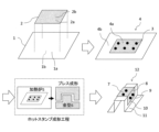
- FIG. 2 is an explanatory diagram schematically showing an example of a method for manufacturing a laminated hot stamp molded body for obtaining a laminated hot stamp molded body using a hot stamp laminated blank according to an embodiment of the present invention.
- FIG. 2 is an explanatory diagram schematically showing the structure of an Al-based plated steel plate having an Al-based plated layer on the surface of a base steel plate of the overlapping blank for hot stamping according to the same embodiment.
- FIG. 7 is a diagram showing a comparative example in which the plate temperatures of the overlapped portion and the single sheet portion were actually measured when overlap spot welding was performed and hot stamp heating was performed.
- the first steel plate is an Al-based plated steel plate, and the area is larger than that of the first steel plate having a carbon-based black film on the upper layer of the Al-based plated steel plate.
- FIG. 7 is a diagram showing an example of the invention in which the plate temperatures of the overlapped portion and the single sheet portion were actually measured when a small second steel plate was overlapped and spot welded and heated by hot stamping.
- FIG. 7 is a diagram showing the relationship between the heating temperature T1 and the heating times t1, t2+ ⁇ t2, and t2+ ⁇ t2' in the method for manufacturing a laminated hot-stamped molded body according to the same embodiment.
- the laminated hot-stamped molded article according to the embodiment has an Al-Fe alloy plating layer on the surface of the base steel plate, and a diffusion layer included in the Al-Fe alloy plating layer and in contact with the steel plate base material.
- FIG. 1 is an explanatory diagram schematically showing an example of a method for manufacturing a laminated hot-stamped molded body according to an embodiment of the present invention.
- a hot-stamped laminated blank is used as a material for the laminated hot-stamped molded body.
- the overlapping blank for hot stamping according to this embodiment is a type of tailored blank, and is also called a patchwork blank.
- a hot-stamping laminated blank 4 includes a first Al-based plated steel plate 1 and a first Al-based plated steel plate 1. It is constructed by welding 3 a second Al-based plated steel plate 2 which has a smaller area than the plated steel plate.
- the part where the second Al-based plated steel plates 2 are stacked is called a stacked part 4a, and the part where they are not stacked is called a one-piece part 4b.
- the second Al-based plated steel plate 2 is different from the first one as schematically shown in FIG. It is preferable that the first Al-based plated steel sheet 1 is disposed inside the outer edge of the first Al-based plated steel sheet 1 so that there is no protruding portion from the Al-based plated steel sheet 1 .
- the surface of the first Al-based plated steel sheet 1 has a surface 1a that is in contact with the second Al-based plated steel sheet 2, and a surface 1b that is not in contact with the second Al-based plated steel sheet 2.
- an Al-based plating layer is applied, and similarly, the second Al-based plated steel sheet 2 has a surface 2a in contact with the first Al-based plated steel sheet 1 and a surface 2a in contact with the first Al-based plated steel sheet 1.
- An Al-based plating layer is applied to both sides of the side 2b that is not covered.
- an upper layer of the Al-based plating layer is provided on the side 2b of the second Al-based plated steel sheet that is not in contact with the first Al-based plated steel sheet.
- a carbon-based black film (not shown) is provided on the surface.
- the surface of the first Al-based plated steel sheet 1 has a surface 1a on the side that is in contact with the second Al-based plated steel sheet 2
- An Al-based plating layer is applied to both sides of the surface 1b that is not in contact with the second Al-based plated steel plate 2
- the second Al-based plated steel plate 2 is similarly coated with the first Al-based plated steel plate.
- An Al-based plating layer is applied to both the surface 2a that is in contact with the first Al-based plated steel sheet 1 and the surface 2b that is not in contact with the first Al-based plated steel sheet 1.
- a carbon-based black film (not shown) is provided on the upper layer of the Al-based plating layer. Also, on the side 1b of the first Al-based plated steel sheet that is not in contact with the second Al-based plated steel plate, a carbon-based black film (not shown) is provided on the upper layer of the Al-based plating layer.
- the hot stamping stacked blank 4 is heated in a heating furnace 5 to an Ac point of 3 or more, so that the steel plate is austenitized, and the steel plate is heated immediately after being taken out from the furnace.
- the steel plate undergoes martensitic transformation by being press-formed in the mold 6 and rapidly cooled.
- the stacked hot stamping blank 4 becomes the stacked hot stamped molded body 12 according to the present embodiment, which has excellent collision resistance.
- the existence of a portion that will become the bent portion 8 when the superposed hot stamped molded product 12 is formed is present in at least a part of the overlapped portion 4a, which improves the collision characteristics of the parts of the hot stamped molded product. Preferable from this point of view.
- FIG. 1 shows a molded product using a hat-shaped mold as an example of the superimposed hot stamp molded product 12, and the parts of the hot stamp molded product 12 are named as the top part 7, the bent part of the top part, and section 8, vertical wall section 10, flange section 11, and bent section 9 of the flange section.
- the second Al-based plated steel plate 2 according to the present embodiment is arranged on the outer side of the crown part 7, but the second Al-based plated steel plate 2 is arranged inside the crown part 7.
- the object of the present invention can also be achieved by doing so.
- the stacked blank 4 for hot stamping includes the first Al-based plated steel plate 1 and the first Al-based plated steel plate 1 welded to the first Al-based plated steel plate 1.
- a second Al-based plated steel plate 2 having a smaller area, and Al-based plating is applied to both surfaces of each of the first Al-based plated steel plate 1 and the second Al-based plated steel plate 2.
- the first Al-based plated steel sheet 1 and the second Al-based plated steel sheet 2 according to the present embodiment are Al-based plated steel sheets that have Al-based plating layers on both surfaces of the base steel plate.
- the chemical composition of the base steel plate in each of the first Al-based plated steel plate 1 and the second Al-based plated steel plate 2 is not particularly limited. However, for example, in order to obtain a tensile strength of 1500 MPa or more (Vickers hardness (i.e.
- the chemical composition is , in mass%, C: 0.19 to 0.50%, Si: 0.01 to 1.50%, Mn: 0.4 to 2.0%, Cr: 0.01 to 1.00%, Ti : 0.001 to 0.100%, B: 0.0005 to 0.0100%, P: 0.100% or less, S: 0.100% or less, Al: 0 to 1.000%, N: 0 to 0.0100%, Nb: 0 to 0.100%, Mo, Ni, Cu, Co, W, Sn, V, Sb: 0 to 0.500%, respectively, Mg, Ca, Zr, REM, O: each , 0 to 0.0100%, the balance being Fe and impurities.
- the chemical composition of the base steel plate of the first Al-based plated steel plate 1 and the chemical composition of the base steel plate of the second Al-based plated steel plate 2 are the same. They may be
- the method for producing an Al-based plated steel sheet using the above chemical composition as a base material steel sheet is not particularly limited.
- a material manufactured through a conventional iron-making process and steel-making process hot rolling, pickling, cold rolling, and Sendzimir hot-dip aluminizing.
- the plate thickness d1 (mm) of the first Al-based plated steel plate 1 and the plate thickness d2 (mm) of the second Al-based plated steel plate 2 are selectively set to 0.5 mm or more, respectively. It is preferably 2 mm or less.
- the plate thickness By setting the plate thickness to 0.5 mm or more, it becomes possible to maintain the productivity of the hot rolling and cold rolling processes at a desired level.
- the plate thickness by setting the plate thickness to 3.2 mm or less, it is possible to prevent the phenomenon in which the desired tensile strength cannot be obtained due to a decrease in the cooling rate during hot stamping mold hardening, resulting in insufficient hardenability. becomes possible.
- the plate thickness d1 of the first Al-based plated steel plate 1 and the plate thickness d2 of the second Al-based plated steel plate 2 can be measured using, for example, a micrometer compliant with JIS B7502:2016.
- the plate thicknesses d1 and d2 mentioned above include the thickness of the Al-based plating layer provided on both sides in addition to the plate thickness of the base steel plate.
- An increase in the total plate thickness slows down the rate of temperature rise in the overlapping portion, reducing productivity during hot stamp heating. Therefore, the total plate thickness d is set to 4.8 mm or less. That is, d satisfies the following formula (c). 2.5 ⁇ d ⁇ 4.8... Formula (c)
- the total plate thickness d is preferably 4.6 mm or less, more preferably 4.4 mm or less, 4.2 mm or less, or 4.0 mm or less.
- the total plate thickness d is set to 2.5 mm or more.
- the total plate thickness d is preferably 2.8 mm or more, more preferably 3.2 mm or more.
- the amount of the Al-based plating layer applied to both surfaces of the first Al-based plated steel sheet 1 is W1a (g/m 2 ) on the surface 1a in contact with the second Al-based plated steel sheet 2; On the surface 1b on the side not in contact with the second Al-based plated steel plate 2, W1b (g/m 2 ). Further, the amount of adhesion of the Al-based plating layer applied to both surfaces of the second Al-based plated steel sheet 2 is W2b (g/m 2 ) on the surface 2b on the side not in contact with the first Al-based plated steel sheet 1. be.
- the values of W1a, W1b, and W2b are each independently within the range of 20 g/m 2 or more and 120 g/m 2 or less per side.
- the average adhesion amount of the Al-based plating layer on the non-overlaid portion (single-sheet portion 4b) of the overlapping blank 4 for hot stamping is defined as W1 (g/m 2 ) per side.
- W1a the adhesion amount of the Al-based plating layer on one side of the surface in contact with the second Al-based plated steel sheet 2
- W1b the adhesion amount of the Al-based plating layer on one side of the surface not in contact with the system-plated steel sheet 2
- W1 0.5 ⁇ (W1a+W1b).
- the average amount of Al-based plating layer deposited on the overlapping portion 4a of the overlapping blank 4 for hot stamping is defined as W2 (g/m 2 ) per side.
- the adhesion amount of the Al-based plating layer on one side of the surface 1b of the first Al-based plated steel sheet 1 that is not in contact with the second Al-based plated steel sheet 2 is W1b (g/m 2 )
- W2b 0.5 ⁇ (W1b+W2b).
- the surface 1a on the side that is in contact with the second Al-based plated steel sheet 2 the surface 1b on the side that is not in contact with the second Al-based plated steel sheet 2, and the second Al-based plated steel sheet 1.
- the surface 2b on the side not in contact with the first Al-based plated steel plate 1 is a surface exposed to a heat source when the manufactured stacked blanks are heated in the hot stamp. This is an important surface in controlling the rate of temperature increase.
- the amount of plating deposited on the Al-based plating layer according to this embodiment is not particularly limited.
- the properties required for hot stamped products are (a) suppression of Fe scale generation during hot stamping, and (b) prevention of plating caused by sliding off of the plating (also called powdering) during hot stamping.
- Preferable characteristics include suppressing chips and scratches.
- Powdering occurs due to compressive stress applied to the plating on the inner surface of a bent part that occurs during molding, and shear stress applied to the plating due to sliding from the mold during molding. If the adhesion amounts W1 and W2 of the Al-based plating layer on each steel plate are less than 20 g/m 2 , the thickness of the plating becomes thin, causing a problem in which Fe scale is insufficiently suppressed. Therefore, it is preferable that the adhesion amounts W1 and W2 of the Al-based plating layer on each steel plate are independently 20 g/m 2 or more.
- the adhesion amounts W1 and W2 of the Al-based plating layer on each steel plate are each independently more preferably 30 g/m 2 or more, and still more preferably, in order of preference, 35 g/m 2 or more, 40 g/m 2 or more, It is 45 g/m 2 or more, and 50 g/m 2 or more.
- the coating amounts W1 and W2 of the plating per side of each steel plate are each independently 120 g/m 2 or less.
- the amount of coating W1 and W2 per one side of each steel plate is independently more preferably 110 g/m 2 or less, and still more preferably 100 g/m 2 or less, 95 g/m 2 or less, and 90 g. / m2 or less. Note that, in the second Al-based plated steel sheet, the amount of the Al-based plating layer deposited on the surface of the second Al-based plated steel sheet in contact with the first Al-based plated steel sheet is not particularly specified.
- between the coating amounts W1 and W2 of the plating per side of each steel plate is 40 g/m 2 or less.
- is more preferably 35 g/m 2 or less, 30 g/m 2 or less, 25 g/m 2 or less, or 20 g/m 2 or less.
- the thickness ( ⁇ m) of the Al-based plating layer on each steel plate can be roughly estimated from the coating weight (g/m 2 ), and although it depends on the chemical composition of the Al-based plating layer, it can be roughly calculated by the following formula ( 1).
- FIG. 2 schematically shows the layer structure on one side of the Al-based plated steel sheet 13 in which the Al-based plated layer according to the present embodiment is provided on the surface of the base steel sheet.
- Al-based plating layer according to the present embodiment is manufactured by a hot-dip plating method, an aluminum-iron-based (Al-Fe-based) alloy layer ( ) is formed.
- the hot-dip plating method which is a common method for applying Al-based plating to a base steel plate
- the amount of adhesion is adjusted by immersing the base steel plate in a hot-dip aluminum plating bath and wiping with gas such as nitrogen or air. It is possible to produce an Al-based plated steel sheet.
- an aluminum-iron alloy layer is inevitably formed at the interface between the Al-based plating layer 14 and the base steel plate 15 in FIG. 2 due to the elution of Fe during hot-dip plating.
- the Al-based plating layer 14 in FIG. 2 also includes an aluminum-iron alloy layer.
- the chemical composition of the hot-dip aluminum plating bath for forming the Al-based plating layer (that is, the chemical composition is substantially the same as the Al-based plating layer 14 except for Fe) is not particularly limited.
- the content of Al in the hot-dip aluminizing bath is preferably 80% by mass or more in terms of excellent heat resistance required during hot stamp heating.
- the Si content of the hot-dip aluminizing bath is preferably 2% by mass or more. By setting the Si content to 2% by mass or more, it is possible to prevent the aluminum-iron alloy layer from becoming too thick and reducing formability.
- the Si content of the hot-dip aluminizing bath to 15% by mass or less, it is possible to prevent the alloying reaction during hot stamp heating from slowing down and reducing hot stamp productivity. .
- the hot-dip aluminizing bath contains 2% by mass or more and 15% by mass or less of Si
- a eutectic structure of Al and Si is formed in the Al-based plating layer 14 formed using such a plating bath based on the phase diagram. be done.
- Fe may inevitably be contained as a component eluted from the base steel sheet in an amount of 1% by mass or more and 5% by mass or less.
- Other unavoidable impurities include Cr, Mn, Zn, V, Ti, Sn, Ni, Cu, W, Bi, Mg, Ca, etc. caused by eluted components from hot-dip plating equipment and impurities in ingots from hot-dip aluminizing baths. These elements may be contained in an amount of less than 1% by mass.
- the chemical composition (average chemical composition) of the Al-based plating layer 14 according to the present embodiment is, in mass %, Al: 80 to 97%, Si: 2 to 15%, Fe: 1 to 15%, Cr: 0. % or more and less than 1%, Mo: 0% or more and less than 1%, Zn: 0% or more and less than 1%, V: 0% or more and less than 1%, Ti: 0% or more and less than 1%, Sn: 0% or more and less than 1%.
- the plating layer may contain less than 1% of the content, with the remainder being impurities.
- the hot-dip aluminizing bath inevitably contains Fe in an amount of 1% by mass or more and 5% by mass or less, whereas an aluminum-iron alloy layer is formed in the Al-based plating layer. , the proportion of Fe increases. Therefore, the chemical composition of the Al-based plating layer 14 may be Fe: 1 to 15%.
- the metal structures of the aluminum-iron alloy layer include ⁇ phase (FeAl 3 ), ⁇ phase (Fe 2 Al 5 ), ⁇ phase (FeAl 2 ), Fe 3 Al, and FeAl 2 which are binary alloys of Al and Fe. , Al solid solution BCC phase ( ⁇ 2, ⁇ ), and the combination of these plating phases constitutes an aluminum-iron alloy layer.
- the metal structures of the aluminum-iron alloy layer containing Si include ⁇ 1 phase (Al 2 Fe 3 Si 3 ), ⁇ 2 phase (Al 3 FeSi), ⁇ 3 phase (Al 2 FeSi), and ⁇ 4 phase (Al 3 FeSi 2 ), ⁇ 5 phase (Al 8 Fe 2 Si), ⁇ 6 phase (Al 9 Fe 2 Si 2 ), ⁇ 7 phase (Al 3 Fe 2 Si 3 ), ⁇ 8 phase (Al 2 Fe 3 Si 4 ), ⁇ 10 phase ( (Al 4 Fe 1.7 Si), ⁇ 11 phase (Al 5 Fe 2 Si) (however, each phase may not have a stoichiometric composition), and the metal of the aluminum-iron alloy layer.
- the structure is often mainly composed of ⁇ 5 phase or ⁇ phase.
- the amount of the Al-based plating layer deposited on one side should be determined according to JIS G 3314:2019 JB. It is measured using method 3 (sodium hydroxide-hexamethylenetetramine/hydrochloric acid peel weight method).
- the surface 1a on the side that is in contact with the second Al-based plated steel plate 2 is expressed as L * 1a
- the side that is not in contact with the second Al-based plated steel plate 2 is expressed as L*1a
- the surface 1b of is expressed as L * 1b
- the lightness L * of the surface of the second Al-based plated steel plate 2 is expressed as L * 2b on the surface 2b on the side not in contact with the first Al-based plated steel plate 1.
- L * 1 0.5 ⁇ (L * 1a+L * 1b)
- the overlapping blank 4 for hot stamping satisfies either condition (A) or (B) below depending on how the carbon-based black film is provided.
- L * b is 40 or more and 60 or less.
- L * 1 is (L * b+20) or more and 80 or less.
- the second Al-based plated steel sheet has a carbon-based black film on the upper layer of the Al-based plating layer on the side not in contact with the first Al-based plated steel sheet, and in the first Al-based plated steel sheet,
- L * b is 20 or more and less than 40
- L * 1 is (L * b+20). 60 or less.
- L * 1 means the average brightness of the surface of the Al-based plating layer in the non-overlapping portion (single-sheet portion 4b) of the overlapping blank 4 for hot stamping.
- Al-based plated steel sheets it is possible to obtain high brightness due to the silver-white metallic luster on the surface, and the thickness of the Al-based plated layer (the amount of adhesion of the Al-based plated layer) ), it is possible to suppress the blackening of the plating surface caused by the alloying of the plating reaching the surface, and it is possible to maintain high brightness even during hot stamping heating. I found it. Furthermore, by using a carbon-based black film on the upper layer of the Al-based plated steel sheet, the brightness can be lowered. In this way, by appropriately controlling the Al-based plating layer and the carbon-based black film used in the Al-based plated steel sheet, it is possible to adjust the brightness to a desired value.
- L * b is 40 or more and 60 or less, and L * 1 is (L * b+20) or more and 80 or less. That is, L * b satisfies formula (a), and L * 1 satisfies formula (b).
- L * b satisfies formula (a)
- L * 1 satisfies formula (b).
- L * b is set to 60 or less.
- L * b is preferably 58 or less, more preferably 56 or less, still more preferably 54 or less.
- L * b is set to 40 or more.
- L * b is preferably 42 or more, more preferably 44 or more, still more preferably 46 or more.
- L * 1 is set to be (L * b+20) or more.
- L * 1 is preferably (L * b+22) or more, more preferably (L * b+24) or more.
- L * 1 is set to 80 or less.
- L * 1 is preferably 78 or less, more preferably 76 or less.
- L * b is 20 or more and 40 or less, and L * 1 is (L * b+20) or more and 60 or less. That is, L * b satisfies formula (A), and L * 1 satisfies formula (B). 20 ⁇ L * b ⁇ 40...Formula (A) (L * b+20) ⁇ L * 1 ⁇ 60...Formula (B)
- L * b exceeds 40, the temperature increase rate is not sufficiently improved. Therefore, L * b is set to 40 or less. When L * b is 40 or less, the heating rate of the hot stamp in the overlapping portion is further improved. Furthermore, unlike the above-mentioned case (A), the second Al-based plated steel sheet has a carbon-based black film on the upper layer of the Al-based plating layer on the side not in contact with the first Al-based plated steel sheet, and Since the first Al-based plated steel sheet has a carbon-based black film on the upper layer of the Al-based plating layer on the side not in contact with the second Al-based plated steel sheet, it is possible to suppress the formation of an excessive thickness of the film. As a result, the generation of dust can be suppressed during the spot welding 3 when manufacturing the stacked blanks 4 shown in FIG. 1, as described above. L * b is preferably 38 or less, more preferably 36 or less, still more preferably 34 or less.
- L * b is set to 20 or more.
- L * b is preferably 22 or more, more preferably 24 or more.
- L * 1 is set to be (L * b+20) or more.
- L * 1 is preferably (L * b+22) or more, more preferably (L * b+24) or more.
- L * 1 is set to 80 or less.
- L * 1 is preferably 78 or less, more preferably 76 or less.
- FIG. 3 shows the layer structure on one side of an Al-based plated steel plate 16 in which an Al-based plated layer 14 is provided on the surface of a base steel plate 15 according to the present embodiment, and a carbon-based black film 17 is further provided on the upper layer. , is shown schematically.
- a carbon-based black film 17 is provided on the upper layer of the Al-based plating layer located on the surface 2b on the side not in contact with the first Al-based plated steel sheet 1.
- An Al-based plated steel sheet has a surface with a silvery white metallic luster, resulting in high brightness.
- the carbon-based black film 17 is burnt off by oxidation reaction during heating during hot stamping, and is emitted as CO 2 or the like. As a result, it is possible to suppress deterioration in spot weldability of overlapping hot-stamped parts due to the remaining carbon-based black film 17.
- a method for lowering the brightness without using a carbon-based black film includes a method of alloying the plating to the surface by heating at about 700 to 800°C.
- carbides precipitate in the base steel sheet, the collision properties after hot stamping deteriorate, and it is not preferable to use it as a material for hot stamping laminated blanks.
- Other methods for lowering the brightness without using a carbon-based black film include electroplating Zn, Zn-Ni, or Zn-Fe on the top layer of the Al-based plating layer, or using an Al-based plated steel sheet. A method of pickling treatment is mentioned.
- oxides on the surface of the Al-based plating layer increase after heating with the hot stamp, which leads to dust generation during spot welding, so care must be taken.
- the first Al-based plated steel sheet 1 it is preferable to provide a carbon-based black film on the upper layer of the Al-based plating layer located on the surface 1b of the side not in contact with the second Al-based plated steel sheet 2.
- a carbon-based black film on the upper layer of the Al-based plating layer located on the surface 1b of the side not in contact with the second Al-based plated steel sheet 2.
- the second Al-based plated steel plate 2 the surface located on the surface 2a on the side that is in contact with the first Al-based plated steel plate 1, and in the first Al-based plated steel plate 1, the second Al-based plated steel plate It is preferable that no carbon-based black film be provided on any of the surfaces located on the surface 1a in contact with 2. Since entry of oxygen necessary for combustion of the film is inhibited on the side in contact with the steel plate, an unburned carbon-based black film remains, which becomes a factor that reduces the spot weldability of the hot stamped body.
- the surface of the Al-based plated steel sheet is heated to about 500 to 600°C to oxidize it to whiten it.
- An example of this is letting people know.
- the thickness of such a carbon-based black film is preferably 0.3 ⁇ m or more and 10 ⁇ m or less. By setting the thickness of the carbon-based black film to 0.3 ⁇ m or more, it is possible to suppress an increase in brightness and increase the rate of temperature rise in the overlapped portion.
- the thickness of the carbon-based black film is more preferably 0.4 ⁇ m or more, and even more preferably 0.5 ⁇ m or more, 0.6 ⁇ m or more, and 0.7 ⁇ m or more in order of preference.
- the thickness of the carbon-based black film is more preferably 8 ⁇ m or less, and even more preferably 6 ⁇ m or less, 5 ⁇ m or less, and 4 ⁇ m or less, in order of preference.
- the thickness of the carbon-based black film can be determined by observing the cross section of the plating with an optical microscope (for example, area: 100 ⁇ m x 100 ⁇ m) (no etching), and measuring the thickness of the film above the aluminum plating layer as shown in Figure 3. It can be obtained as the average value of the thickness of the film measured in each of the three fields of view. At this time, the film is analyzed in cross section using an electron probe microanalyzer (EPMA), and if the carbon content is 30% by mass or more, it is determined that it is a carbon-based black film. A black film is determined from the fact that the lightness L * value from the surface is 60 or less.
- EPMA electron probe microanalyzer
- the carbon-based black film may optionally contain a resin as a binder to improve adhesion to the Al-based plating layer.
- the type of resin is not particularly limited, and examples thereof include polyethylene resin, polyolefin resin, polyacrylic resin, polymethacrylic acid resin, polyepoxy resin, polyurethane resin, and polycarbonate resin.
- At least one of Zn, Ti, Cu, and V in the carbon-based black film At least one of Zn, Ti, Cu, or V is selectively applied to the carbon-based black film located further above the Al-based plating layer applied to the surface of the second Al-based plated steel sheet 2. It is preferable to contain the types in a total amount of 0.1 g/m 2 or more and 3.0 g/m 2 or less.
- the amount of deposited here refers to the amount of Zn, Ti, Cu, or V deposited per unit area.
- Zn, Ti, Cu, and V are elements constituting an oxide that not only improves emissivity but also has good infrared absorption.
- the carbon-based black film 17 described above is burned away during hot stamp heating, whereas Zn, Ti, Cu, or V remains even during hot stamp heating. Therefore, the carbon-based black film containing such elements can further contribute to improving the temperature increase rate at high temperatures.
- Zn, Ti, Cu, and V may be contained in either a metal state or an oxide state. This is because both become oxides during the temperature rise and contribute to improving the emissivity.
- the total adhesion amount of such elements in the carbon-based black film is preferably 0.1 g/m 2 or more.
- the total adhesion amount of such elements in the carbon-based black film is more preferably 0.2 g/m 2 or more, still more preferably 0.3 g/m 2 or more, even more preferably 0.5 g/m 2 That's all.
- the total adhesion amount of such elements in the carbon-based black film is more preferably 2.5 g/m 2 or less, still more preferably 2.0 g/m 2 or less.
- the adhesion amount (content) of Zn, Ti, Cu, and V can be determined by elemental analysis from the surface using, for example, a fluorescent X-ray analyzer (ZSX Primus, manufactured by RIGAKU). It can be determined by quantifying the amount of V attached.
- the method for treating the carbon-based black film 17 described above is not particularly limited, but examples include water-dispersed carbon black (for example, RCF#52 manufactured by Mitsubishi Chemical Corporation), zinc oxide (for example, Nano Tek) or titanium oxide (for example, Nano Tek manufactured by CI Kasei Co., Ltd.), copper oxide (for example, Nano Tek manufactured by CI Kasei Co., Ltd.), vanadium oxide (manufactured by Hongwu International Group Ltd.) are dispersed in water. It can be manufactured by preparing a water-based coating liquid, performing the above-mentioned molten aluminum plating treatment, coating with a roll coater, and performing a dry baking treatment. Alternatively, it can be manufactured by vacuum-depositing Zn, Ti, Cu, or V metal onto an aluminized steel plate.
- water-dispersed carbon black for example, RCF#52 manufactured by Mitsubishi Chemical Corporation
- zinc oxide for example, Nano Tek
- titanium oxide for example, Nano Tek manufactured by CI Kasei Co.,
- the carbon-based black film 17 and at least one of Zn, Ti, Cu, or V may be included in the coating layer 17'.
- the arrangement order of the carbon-based black film 17 and the film layer 17' having at least one of Zn, Ti, Cu, or V is not particularly limited, and the carbon-based black film 17 may be located above the coating layer 17' containing at least one of Zn, Ti, Cu, or V, or a coating containing at least one of Zn, Ti, Cu, or V.
- Layer 17' may be located on top of carbon-based black coating 17.
- the carbon-based black film 17 even if the film layer 17' containing at least one of Zn, Ti, Cu, or V is located below the carbon-based black film 17, the carbon-based black film 17 according to this embodiment If the film thickness is , fluorescent X-rays easily pass through the carbon-based black film 17. Therefore, even if the film layer 17' containing at least one of Zn, Ti, Cu, or V is located below the carbon-based black film 17, Zn, Ti, and , Cu, and V can be measured.
- the carbon-based black film 17 and the film layer 17' containing at least one of Zn, Ti, Cu, or V may be provided on both sides of the base steel plate; In this case, it is more preferable to provide only the surface exposed to the heat source during heating of the hot stamp.
- the types of welding include spot welding, seam welding, brazing welding, laser welding, Welding, plasma welding, arc welding, etc. can be selected.
- spot welding is used, which can contact the inside of the overlapped part at multiple points and directly join the steel plates by applying pressure. preferable.
- the laminated hot-stamped molded body 12 of this embodiment is manufactured by providing a bent portion that is subjected to a bending process.
- Particularly important matters in this embodiment include precisely controlling the heating time and heating temperature.
- the temperature rising time of the thick stacked part is slower than the temperature rising time of the single sheet part.
- heating productivity is slow due to the purpose of heating the blank to a temperature higher than the austenitizing temperature and the purpose of equalizing the plate temperature of the blank.
- a long heating time is ensured in accordance with the temperature rising time of the overlapped portion, the single sheet portion whose temperature rises quickly will undergo an excessive heating time.
- the alloying reaction of the aluminum plating progresses excessively, resulting in a problem that the spot weldability of the laminated hot-stamped body deteriorates.
- the second Al-based plated steel plate 2 with a smaller area of the stacked blank of FIG. By providing a carbon-based black film on the surface of the non-overlapping side 2b, the brightness can be reduced and the temperature increase rate can be improved. At this time, the excessive heating time of the single sheet part whose temperature rises quickly is also shortened, the alloying reaction of the aluminum plating is also suppressed, and the spot weldability of the laminated hot stamped body is improved.
- t1 minutes or more is calculated using the following formulas (d) to (f). , (t2+ ⁇ t2) (minutes) or less
- the heated blanks are molded with a mold, and at the same time, the mold (if necessary, the cooling rate of the molded blanks is adjusted).
- the molded blank is cooled (quenched) by removing heat from the mold (cooling water passing through the mold). As a result, a laminated hot-stamped molded body 12 having excellent collision resistance is obtained.
- the times t1 and t2 are determined as the solutions of quadratic equations regarding the times t1 and t2, as shown in the following equations (d) and (e), but t1 is determined by the 2 of the following equation (d). t2 is the smaller value among the solutions of the following equation, and t2 is the smaller value among the solutions of the quadratic equation of the following equation (e).
- T1 A1 ⁇ t1 2 +B1 ⁇ t1+C1 ...
- A1 -0.3645d 5 +6.343d 4 -43.822d 3 +151.71d 2 -268.89d+205.68 ...
- B1 +2.9347d 5 -47.313d 4 +298.84d 3 -936.35d 2 +1518.1d-1197.6 ...
- C1 1381.57...
- T1 A2 ⁇ t2 2 +B2 ⁇ t2+C2 ...
- A2 -0.4367d1 5 +7.3789d1 4 -49.107d1 3 +161.95d1 2 -269.2d1+188.97 ...
- B2 +1.8594d1 5 -31.034d1 4 +204.62d1 3 -675.11d1 2 +1159.2d1-964.59 ...
- t1 which is determined as the smaller value of the solutions of the quadratic equation of the above equation (d), is more specifically calculated from the following equation (d').
- t1 [-B1- ⁇ B1 2 -(4 ⁇ A1 ⁇ (C1-T1)) ⁇ 0.5 ]/2 ⁇ A1 ...Formula (d')
- t2 which is determined as the smaller value among the solutions of the quadratic equation of the above equation (e), is more specifically calculated from the following equation (e').
- t2 [-B2- ⁇ B2 2 -(4 ⁇ A2 ⁇ (C2-T1)) ⁇ 0.5 ]/2 ⁇ A2 ...Formula (e')
- the present inventors investigated the heating process in hot stamping using radiant heat while changing the thickness of the steel plates constituting the laminated blanks and taking into account actual operating conditions.
- Numerical calculation simulations were performed based on the heat transfer equation for heating and a diffusion model regarding the plating alloying reaction. From these simulation results, we were able to obtain knowledge regarding the temperature increase time and the formation time of the diffusion layer, and based on the obtained knowledge, we formulated the conditions that the heating temperature and heating time should satisfy.
- the results of the formulation are the above relational expressions.
- the heating time t is less than the above-mentioned t1 (minutes), the heating is not sufficient and the martensitic transformation of the overlapping portion after hot pressing is not sufficient, resulting in a decrease in material hardness. The crashworthiness of the part is reduced. Furthermore, if the heating time t exceeds the aforementioned (t2+ ⁇ t2) (minutes), the heating of one sheet will take an excessively long time, and as a result, the alloying reaction of the aluminum plating will proceed excessively, causing the spot Weldability deteriorates.
- the heating time it is preferable to set the heating time to (t2+ ⁇ t2) or less, and at the same time, use the following formula (f') to set the heating time to (t2+ ⁇ t2') or less.
- the alloying reaction of aluminum plating is further suppressed, and spot weldability is further improved.
- ⁇ t2' ⁇ t2 as shown in FIG. 7, if the heating time is (t2+ ⁇ t2') or less, the heating time will always be (t2+ ⁇ t2) or less. Therefore, if the heating time is set to be less than or equal to (t2+ ⁇ t2'), calculations related to formula (f), etc. may be omitted.
- the laminated hot stamp molded product has excellent hot stamp productivity and spot weldability. can be obtained.
- the upper limit of the heating time t By setting the upper limit of the heating time t to (t2 + ⁇ t2), it is possible to avoid unnecessary prolongation of the heating time, which was conventionally determined while ensuring a safety margin based on the results of preliminary tests, etc., and to reduce the heating time. It becomes possible to logically determine the upper limit of t, and as a result, it becomes possible to further improve productivity.
- the upper limit of the heating time t to (t2+ ⁇ t2), it becomes possible to suppress an increase in the thickness of the diffusion layer in the manufactured hot stamp molded body, which contributes to improving spot weldability. That will happen.
- a carbon-based black film is provided on the surface of the non-overlapping side 2b of the second Al-based plated steel sheet 2 having a small area of the overlapping blank in FIG.
- the temperature increase rate during heating in hot stamping can be further improved.
- the thickness of the carbon-based black film on the above-mentioned surface 2b and the film thickness of the carbon-based black film on the surface 1b may be the same or different. At this time, the excessive heating time of the single sheet part whose temperature rises quickly is also shortened, the alloying reaction of the aluminum plating is also suppressed, and the spot weldability of the laminated hot stamped body is improved.
- t is calculated by the following formulas (D) to (F).
- D ambient temperature
- F t is calculated by the following formulas (D) to (F).
- the heated blanks are molded using a mold, and at the same time, the molded blanks are In order to increase the cooling rate of the mold, the mold is cooled by cooling water passing through the mold.) The molded blank is cooled (quenched) by removing heat from the mold. As a result, a laminated hot-stamped molded body 12 having excellent collision resistance is obtained.
- times t3 and t4 are determined as solutions of quadratic equations regarding times t3 and t4, as shown in equations (11) and (15) below, but t3 is determined by 2 of equation (D) below. It is the smaller value among the solutions of the following equation, and t4 is the smaller value among the solutions of the quadratic equation of the following equation (E).
- t3 which is determined as the smaller value of the solutions of the quadratic equation of the above equation (D), is more specifically calculated from the following equation (D').
- t3 [-B3- ⁇ B3 2 -(4 ⁇ A3 ⁇ (C3-T3)) ⁇ 0.5 ]/2 ⁇ A3 ...Formula (D')
- t4 which is determined as the smaller value of the solutions of the quadratic equation of the above equation (E), is more specifically calculated from the following equation (E').
- t4 [-B4- ⁇ B4 2 -(4 ⁇ A4 ⁇ (C4-T3)) ⁇ 0.5 ]/2 ⁇ A4 ...Formula (E')
- the present inventors changed the thickness of the steel plates constituting the laminated blanks, and while taking into account the actual operating conditions of the heating process in hot stamping, the inventors Numerical calculation simulations were conducted based on the heat transfer equation for heating up at 100° C. and the diffusion model for the plating alloying reaction. From these simulation results, we were able to obtain knowledge regarding the temperature increase time and the formation time of the diffusion layer, and based on the obtained knowledge, we formulated the conditions that the heating temperature and heating time should satisfy. The results of the formulation are the above relational expressions.
- the heating time t is less than the above-mentioned t3 (minutes), the heating is not sufficient and the martensitic transformation of the overlapping portion after hot pressing is not sufficient, resulting in a decrease in material hardness. The crashworthiness of the part is reduced.
- the heating time t exceeds the above-mentioned (t4+ ⁇ t4) (minutes), the heating of one sheet will take an excessively long time, and as a result, the alloying reaction of the aluminum plating will proceed excessively, causing the spot Weldability deteriorates.
- the heating time it is preferable to set the heating time to (t4+ ⁇ t4) or less, and at the same time, use the following formula (F') to set the heating time to (t4+ ⁇ t4') or less. This further suppresses the alloying reaction of aluminum plating and further improves spot weldability. Note that since ⁇ t4' ⁇ t4, as shown in FIG. 7, if the heating time is (t4+ ⁇ t4') or less, the heating time will always be (t4+ ⁇ t4) or less. Therefore, if the heating time is set to be less than or equal to (t4+ ⁇ t4'), calculations related to equation (F) may be omitted.
- the above heating temperature means the maximum temperature reached by the steel plates in the overlapped portion.
- the heating method include heating using an electric furnace, gas furnace, far-infrared furnace, near-infrared furnace, etc., electrical heating, high-frequency heating, induction heating, and the like.
- an electric furnace, a gas furnace, or a far-infrared furnace is preferable because the stacked blanks tend to have a large area, and large blanks can be heated at a uniform temperature.
- the heating temperature is in a temperature range from Ac3 point (for example, 800° C. or 840° C.) to 1000° C. at which the base steel sheet becomes austenitized.
- the heating temperature is more preferably 860°C or higher, and even more preferably 880°C, in order to improve hardenability by dissolving carbides in the steel sheet and to shorten heating time (improve productivity).
- the temperature is 890°C or higher, or 900°C or higher.
- the heating temperature is more preferably 950° C. or lower, and even more preferably 930° C. or lower, since the heating rate of the overlapping portion and the single sheet portion can be made uniform.
- the above-mentioned heating time means the time from the time when the stacked blank is inserted into the heating furnace to the time when it is extracted from the heating furnace.
- the time from when the stacked blanks are heated until the mold of the press descends for molding and the stacked blanks and the mold come into contact is preferably 3 seconds or more and 20 seconds or less.
- the blank heated to the austenitizing temperature undergoes martensitic transformation by cooling with a mold or a coolant such as water, resulting in a laminated hot-stamped molded product with high strength and excellent collision resistance. is obtained. Therefore, since it is preferable to cool the stacked blanks immediately after heating them, the time taken may be 0 seconds. However, in reality, it often takes 3 seconds or more to convey the blank. Furthermore, if the time taken exceeds 20 seconds, the blank is cooled and transformation from austenite to ferrite begins, and there is a possibility that a martensitic structure will not be obtained in the blank after press forming.
- cooling is performed using a mold or a coolant such as water, and the cooling rate is preferably 30°C/second or more, more preferably 50°C/second or more. .
- the cooling rate (°C/sec) may be calculated as follows. In other words, the time k (seconds) from when the stacked blanks and the die mentioned above come into contact until the die starts to rise after the die is held at the bottom dead center is determined, and A radiation thermometer measures the blank temperature C1 before the two come into contact with each other, and a radiation thermometer measures the blank temperature C2 after the mold is held at the bottom dead center and the mold rises.
- the average cooling rate (C1-C2)/k (°C/sec) may be calculated using the obtained results.
- the laminated hot-stamped molded body 12 according to the present embodiment manufactured as described above includes a first Al--Fe alloy plated steel sheet having a thickness of T1 (mm), and a first Al--Fe alloy plated steel sheet having a thickness of T1 (mm). At least one second Al-Fe alloy plated steel plate is superimposed and welded on the alloy plated steel plate, has a smaller area than the first Al-Fe alloy plated steel plate, and has a plate thickness of T2 (mm). Fe-based alloy plated steel plate.
- the hot stamping molded body 12 is produced after the hot stamping stacked blank 4, in which the first Al-based plated steel plate 1 and the second Al-based plated steel plate 2 are stacked and welded, is heated. , and is manufactured by further applying bending processing and the like.
- the first Al--Fe alloy plated steel sheet and the second Al--Fe alloy plated steel sheet that constitute the hot-stamped compact 12 do not necessarily have a flat shape.
- the first Al--Fe alloy plated steel sheet has a bent portion 8 at the top
- the second Al--Fe alloy plated steel sheet has a bent portion 8 at the top. 8 and a bent portion 9 of the flange portion.
- steel plate the shape is not necessarily flat.
- the former is conveniently replaced with an alloy plated steel plate (for example, an Al-Fe alloy plated steel plate). ), and the latter (without the addition of "alloy”) is called a plated steel sheet (for example, an Al-based plated steel sheet).
- the first Al-Fe alloy plated steel plate in the superimposed hot-stamped compact 12 has Al-Fe alloy plating layers on both sides of the first steel plate, with an average plating thickness of K1 ( ⁇ m) on both sides.
- This is an Al-Fe alloy plated steel sheet.
- the second Al--Fe alloy plated steel sheet in the laminated hot-stamped molded body 12 is an Al-- This is a plated steel sheet having an Fe-based alloy plating layer. Note that, in the second Al--Fe alloy plated steel sheet, the plating thickness of the Al--Fe alloy plating layer on the surface in contact with the first Al--Fe alloy plated steel sheet is not particularly specified.
- the average plating thicknesses K1 and K2 of the Al-Fe alloy plating layer in the first Al-Fe alloy plating steel sheet of the laminated hot-stamped body 12 are each independently 25 ⁇ m or more, It is more preferably 30 ⁇ m or more, and even more preferably 35 ⁇ m or more.
- the average plating thicknesses K1 and K2 of the Al-Fe alloy plating layer in the first Al-Fe alloy plated steel sheet are each independently preferably 60 ⁇ m or less, more preferably 55 ⁇ m or less, More preferably, it is 50 ⁇ m or less.
- the plating thicknesses of the Al-Fe alloy plating layers of the first Al-Fe alloy plated steel sheet and the second Al-Fe alloy plated steel sheet are within the above ranges, so that overlapping hot stamping is possible. It becomes possible to maintain the spot weldability of the body 12 in a good state.
- the above plating thickness was determined by observing a cross section of the plating with an optical microscope (area: 100 ⁇ m x 100 ⁇ m) after nital etching and measuring the plating thickness in 3 fields of view. It can be obtained as a value.
- the plating thickness of the first steel plate there is a position 4b of the single sheet part and a position of the overlapping part 4a which is in contact with the second Al-Fe alloy plated steel sheet, but the temperature increase rate is fast and the thickness is different from that of the hot stamping.
- the plating thickness of the first Al--Fe based alloy plated steel sheet is measured from one part because the heating time is the longest and the spot weldability is likely to deteriorate.
- the Al--Fe alloy plating layer is a layer formed as a result of Fe being diffused to the surface of the Al-based plating layer by heating during hot stamping (in other words, an alloy plating layer containing at least Al and Fe).
- the Al-Fe alloy plating layer is a compound layer of Al and Fe, ⁇ phase (FeAl 3 ), ⁇ phase (Fe 2 Al 5 ), ⁇ phase (FeAl 2 ), Fe 3 Al, FeAl, Al solid solution Fe.
- the Al-Fe alloy plating layer consists of ⁇ 1 phase (Al 2 Fe 3 Si 3 ), ⁇ 2 phase (Al 3 FeSi), ⁇ 3 phase (Al 2 FeSi), and ⁇ 4 phase ( ( Al3FeSi2 ) , ⁇ 5 phase ( Al8Fe2Si ) , ⁇ 6 phase ( Al9Fe2Si2 ), ⁇ 7 phase ( Al3Fe2Si3 ), ⁇ 8 phase ( Al2Fe3Si4 ) , ⁇ 10 phase (Al 4 Fe 1.7 Si) and ⁇ 11 phase (Al 5 Fe 2 Si) (however, each phase may not have a stoichiometric composition), and the Al-Fe alloy plating layer , is often composed mainly of one or more of the ⁇ 1 phase (Al 2 Fe 3 Si 3 ), the ⁇ phase (Fe 2 Al 5 ), FeAl, and solid-dissolved
- the diffusion layer 20 may be a layer in which Al: 30% by mass or less and Fe: 70% by mass or more in the EPMA analysis results.
- the layer 19 is a layer mainly containing the ⁇ phase, ⁇ 1 phase, and FeAl phase, and includes the diffusion layer 20.
- the thickness of the Al--Fe alloy plating layer is measured as the thickness of layer 19
- the thickness of the diffusion layer is measured as the thickness of layer 20.
- FIG. 10 shows an example of a cross-section observed with an optical microscope after nital etching.
- the thickness of the diffusion layer included in the Al-Fe alloy plating layer of the first Al-Fe alloy plated steel sheet, which is not overlapped with the second Al-Fe alloy plated steel sheet, is D1 ( ⁇ m).
- the thickness of the diffusion layer included in the Al--Fe alloy plating layer of the second Al--Fe alloy plated steel sheet is expressed as D2 ( ⁇ m).
- the upper limit of the heating time during heating of the hot stamp is set to a short time of (t2+ ⁇ t2) (or t4+ ⁇ t4), so that the thickness D1 of the diffusion layer ( ⁇ m) and D2 ( ⁇ m) can be independently reduced to 3 ⁇ m or more and 10 ⁇ m or less.
- the thickness of the diffusion layer is 3 ⁇ m or more, it means that the plating is sufficiently alloyed, and it is possible to prevent unalloyed Al from remaining on the surface and prevent deterioration of spot weldability. It becomes possible.
- the thickness of the diffusion layer is more preferably 4 ⁇ m or more, still more preferably 5 ⁇ m or more.
- the thickness of the diffusion layer is more preferably 9 ⁇ m or less, still more preferably 8 ⁇ m or less.
- the spot weldability of the Al-Fe based plating layer is suppressed by the Al-Fe binary alloy (FeAl 3 , Fe 2 Al 5 , FeAl 2 ).
- the Al--Fe binary alloy becomes thicker.
- the plating cross section was subjected to nital etching treatment in a field of view of 100 ⁇ m x 100 ⁇ m, and the plating thicknesses were determined using an optical microscope. Observe its cross section. As shown in FIG. 10, the plating thickness and the thickness of the diffusion layer are measured using an optical microscope. More specifically, the plating cross section is observed at at least three locations using the method described above, and the thickness of the Al--Fe based alloy plating layer 19 and the thickness of the diffusion layer 20 at each observed location is determined.
- the average value of the obtained thicknesses may be calculated, and the obtained average value may be used as the thickness of the Al--Fe alloy plating layer 19 and the diffusion layer 20.
- the diffusion layer cannot be identified by observation using an optical microscope, analysis using an electron probe microanalyzer (EPMA) is performed to determine the thickness of the layer containing at least 30% by mass of Al and 70% by mass or more of Fe. Measurements are made at three locations, and the average value is taken as the thickness of the diffusion layer 20.
- EPMA electron probe microanalyzer
- the thicknesses D1 and D2 of the diffusion layer are almost solely influenced by the heating conditions of hot stamping. and is not affected by the initial plating thickness. Furthermore, even if the coating weight of the second Al-based alloy plated steel sheet is increased, the thickness D2 of the diffusion layer of the second Al-Fe alloy-plated steel sheet, which has a slow heating rate, is different from that of the first Al-Fe alloy plated steel sheet. The thickness cannot be set to approximately the same value as the thickness D1 of the diffusion layer of the alloy-plated steel sheet.
- the plating thicknesses K1 and K2 of the Al--Fe alloy plating layer are affected not only by the plating adhesion before hot stamping, but also by the hot stamping heating conditions (heating temperature, holding time).
- the plating thicknesses K1 and K2 of the Al-Fe alloy plating layer are affected not only by these effects, but also by the sheet thickness and lightness, which affect the heating time at high temperatures, so only the initial plating thickness is affected. Not that I will.
- the laminated hot-stamped molded body 12 of this embodiment is used as an automobile part, it is generally subjected to welding, phosphoric acid chemical conversion treatment, electrodeposition coating, etc. before use. Therefore, for example, a zinc phosphate film and a phosphoric acid film by phosphoric acid chemical conversion treatment, and an organic film of 5 ⁇ m or more and 50 ⁇ m or less by electrodeposition coating on the surface thereof may be formed on the surface of the hot stamp molded body 12. be. After electrodeposition coating, additional coatings such as intermediate coating and top coating may be applied to improve the appearance quality and corrosion resistance.
- Example 1 A first Al-based plated steel plate 1 and a second Al-based plated steel plate 2 shown in Table 1 were fabricated by the method described below, and spot welded 3 as shown in Figure 1 to fabricate a stacked blank 4 for hot stamping. did.
- the first Al-based plated steel sheet 1 is a cold-rolled steel sheet (chemical composition: mass %, C: 0.23%, Si: 0.30%, Mn: 1.
- aluminization treatment was performed on both sides in a Sendzimir hot-dip aluminization treatment line. After plating, the amount of plating deposited on each side was adjusted to 80 g/m 2 by a gas wiping method, and then cooled to produce a first Al-based plated steel sheet 1.
- the plating bath composition at this time was 89% by mass Al, 9% by mass Si, and 2% by mass Fe.
- the surface 1a of the first Al-based plated steel plate in contact with the second Al-based plated steel plate was pickled (5% hydrochloric acid) to lower the brightness.
- the lightness can be improved by pickling (5% hydrochloric acid) both the surface 1a of the first Al-based plated steel sheet that is in contact with the second Al-based plated steel sheet and the surface 1b that is not in contact with the second Al-based plated steel sheet. I processed it to lower it.
- treatment was performed to melt the Al-based plating layer on the surface and increase the brightness by heating at 550°C.
- the second Al-based plated steel sheet 2 was also produced in the same manner as the first Al-based plated steel sheet 1, and a carbon-based black film was applied to the Al-based plated surface with a film thickness of 0.5 to 8.0 ⁇ m.
- the heating rate of the overlapping part was investigated by hot-stamping the blank at the heating temperature shown in Table 1.
- a superimposed hot stamp molded body 12 was obtained.
- Two pieces of the flange portion 11 in the non-overlapping portion (single piece) were cut out, and spot weldability was investigated by assembling the same type of plates.
- Table 1 Each level in Table 1 is compared with examples of the present invention (hereinafter simply referred to as "invention examples”) A2 to A4, A7, A8, A11, A16, A17, A19, A20, A23 to A25, and A27. Examples are shown as A1, A5, A6, A9, A10, A12-A15, A18, A21, A22, A26, A28-A30.
- the plate thicknesses t1 and t2 of the steel plate were measured using a micrometer based on JIS B7502:2016, as described above.
- the thickness of the carbon-based black film was measured from cross-sectional observation as described above.
- the thicknesses D1 and D2 of the diffusion layer of the obtained stacked hot-stamped molded body were measured by cross-sectional observation using an optical microscope as described above (each was measured at three locations and the average value was determined). .
- the second Al-plated steel plate in the laminated part which has the slowest heating rate due to its thickness and the slowest cooling rate by the mold, so the hardness may be lower.
- the hardness of the sample was measured from the cross section using a micro Vickers hardness meter under a load of 9.8107N. The evaluation criteria are as follows, and a rating of G was determined to be good, and a rating of NG (No Good) was determined to be poor.
- the evaluation criteria is the range between the welding current value at which the weld nugget during spot welding can obtain a diameter of 4 ⁇ t (t is the plate thickness) and the welding current value at which dust (splash) is generated (referred to as the appropriate current range). ), a rating of G (Good) was determined to be good, a rating of VG (Very Good) was determined to be even better, and a rating of NG (No Good) was determined to be poor.
- VG Appropriate current range 1.5kA or more
- G Appropriate current range 1.0kA or more but less than 1.5kA
- NG Appropriate current range less than 1.0kA
- Welding power source DC inverter, electrode pressure: 3.9kN
- Electrode shape DR, tip diameter 6 ⁇ (R40) (material: chrome copper)
- Initial pressurization time 60 cycles, welding time 22 cycles, holding time 10 cycles
- Welding current value 4kA to 15kA, welding at 0.2kA pitch
- Table 1 summarizes the evaluation results of the temperature increase rate of the overlapped portion of the blanks and the spot weldability after hot stamping (HS).
- Invention examples A2 to A4, A7, A8, A11, A16, A17, A19, A20, A23 to A25, and A27 have plate thicknesses within the range of the present invention, have a carbon-based black coating, and have a heating temperature of Since the relationship between and heating time satisfied formulas (a) to (f), the hardness and spot weldability of the overlapping portion after hot stamping were good.
- the heating time satisfies formulas (d), (e), and preferred formula (f')
- a more favorable evaluation result of spot weldability of VG can be obtained. .
- Comparative examples A1, A5, A6, A9, A10, and A12 had poor hardness or spot weldability at the overlapping part because the relationship between heating temperature and time did not satisfy formulas (a) to (f). Ta. Comparative examples A13, A14, and A30 did not have a carbon-based black film, so the temperature increase rate was slow and the hardness of the overlapping portion was poor.
- A15 which is a comparative example, since the value of L * 1 did not exceed (L * b+20), overheating of one sheet portion was not suppressed and the spot weldability was poor.
- A18 which is a comparative example, had a value of L * 1 exceeding 80, and therefore had poor spot weldability.
- A21 which is a comparative example
- the value of lightness L * b exceeded 60, so the hardness of the overlapped portion was poor.
- A22 which is a comparative example, the total thickness of the first Al-based plated steel plate and the second Al-based plated steel plate was less than 2.5 mm, so the heating time was excessive and the spot weldability of one part was poor. there were.
- Comparative examples A26, A28, and A29 have a total thickness of more than 4.8 mm of the first Al-based plated steel sheet and the second Al-based plated steel sheet, so the temperature increase rate at the overlapping part is slow and the overlapping The hardness of the mating part was poor.
- Example 2 A first Al-based plated steel plate and a second Al-based plated steel plate were produced under the same manufacturing conditions as level A16 of Example 1, and a carbon-based plate was applied on the Al-based plated steel plate of the second Al-based plated steel plate.
- the lightness L * 2b value was 10
- the L * b value was 39.
- tape peeling (tape: CT405AP-24 manufactured by Nichiban Co., Ltd.), peeling of the film was observed and was not practical. In a similar test, no peeling was observed in A16 and A19.
- Example 3 A first Al-based plated steel sheet and a second Al-based plated steel sheet were manufactured under the same manufacturing conditions as level A3 of Example 1, and the second Al-based plated steel sheet was coated on the Al-based plating layer. , a carbon-based black film was formed. At this time, levels A31, A32, and A33 were created in which the coating weight of the second Al-based plated steel sheet was 55 g/m 2 , 45 g/m 2 , and 30 g/m 2 per side.
- the obtained levels A3, A31, A32, and A33 were heated under the conditions of level A3 in Example 1 to obtain quenched overlapping hot-stamped molded bodies.
- a second Al-Fe alloy plated steel plate is cut out from the obtained superimposed hot-stamped molded body, and spot welded under the same conditions as those described in Example 1 to obtain a second Al-Fe alloy plated steel plate. The spot weldability of the steel was evaluated.
- the scores for levels A3 and A31 were VG, and the scores for levels A32 and A33 were G.
- which is the value obtained by subtracting the coating weight W2 of the second Al-based plated steel sheet from the coating weight W1 of the first Al-based plated steel plate
- is 25 g/m 2
- levels A32 and A33 were values obtained by subtracting the coating weight of the second Al-based plated steel sheet from the coating weight of the first Al-based plated steel sheet
- the hardness of the overlapping portion of standards A31, A32, and A33 and the spot weldability of a portion of the first Al--Fe alloy plated steel plate were rated G and VG, respectively, as in level A3.
- Example 4 Under the same manufacturing conditions as in Example 1 shown in Table 2, a carbon-based black film was applied to the non-overlapping Al-based plated surfaces of each of the first Al-based plated steel sheet and the second Al-based plated steel sheet. It was coated at a thickness of 0.5 to 8.0 ⁇ m.
- the heating rate of the overlapping part was investigated by hot-stamping the blank at the heating temperature shown in Table 1. By rapidly cooling the mold, a superimposed hot-stamped molded product 12 was obtained. Two pieces of the flange portion 11 in the non-overlapping portion (single piece) were cut out, and spot weldability was investigated by assembling the same type of plates.
- Each level in Table 2 indicates the examples of the present invention as B1 to B7.
- a stacked blank heating step of heating the stacked blanks in a heating furnace a heated blank transport step of transporting the heated stacked blanks from the heating furnace and transporting them to a press device; a hot stamping step of pressing the heated stacked blanks with a mold provided in the press device to obtain a stacked hot stamped molded body;
- a method for producing a superimposed hot-stamped molded body comprising:
- the stacked blank includes a first steel plate having a plate thickness of d1 (mm), and at least one plate having a smaller area than the first steel plate, which is stacked and welded on the first steel plate.
- the first steel plate and the second steel plate are Al-based plated steel plates each having an Al-based plating layer on both sides of the steel plate,
- the second steel plate has a carbon-based black film as an upper layer of at least a portion of the Al-based plating layer on the side not in contact with the first steel plate,
- the surface on the side in contact with the second steel plate is L * 1a
- the surface on the side not in contact with the second steel plate is L * 1b
- the average value L * b of L * 1b and L * 2b is 40 or more and 60 or less
- the average value L * 1 of L * 1a and L * 1b is (L * b+20) or more and 80 or less
- ⁇ t2 1.498 ⁇ 10 13 ⁇ e (-0.03198 ⁇ T1) ...Formula (10) [c] a stacked blank heating step of heating the stacked blanks in a heating furnace; a heated blank transport step of transporting the heated stacked blanks from the heating furnace and transporting them to a press device; a hot stamping step of pressing the heated stacked blanks with a mold provided in the press device to obtain a stacked hot stamped molded body; A method for producing a superimposed hot-stamped molded body, comprising: The stacked blank includes a first steel plate having a plate thickness of d1 (mm), and at least one plate having a smaller area than the first steel plate, which is stacked and welded on the first steel plate.
- the first steel plate and the second steel plate are Al-based plated steel plates each having an Al-based plating layer on both sides of the steel plate,
- the first steel plate has a carbon-based black film as an upper layer of at least a portion of the Al plating layer on the side not in contact with the second steel plate,
- the second steel plate has a carbon-based black film as an upper layer of at least a portion of the Al-based plating layer on the side not in contact with the first steel plate,
- the surface on the side in contact with the second steel plate is L * 1a
- the surface on the side not in contact with the second steel plate is L * 1b
- the lightness L * specified in JIS Z 8781-4 on the surface of the second steel plate is L * 2b on the surface not in contact with the first steel plate
- the average value L * b of L * 1b and L * 2b is 20 or more and
Landscapes
- Engineering & Computer Science (AREA)
- Mechanical Engineering (AREA)
- Shaping Metal By Deep-Drawing, Or The Like (AREA)
Abstract
【課題】Al系めっき鋼板を素材として用いた場合に、重ね合わせ部の昇温速度が遅いことと、一枚部が過剰な時間加熱されることの両者を改善すること。 【解決手段】本発明は、板厚d1の第一のAl系めっき鋼板と、前記第一のAl系めっき鋼板上に重ね合わされて溶接された、前記第一のAl系めっき鋼板よりも面積の小さく、かつ、前記第一のAl系めっき鋼板と接しない側の前記Al系めっき鋼板の表面に炭素系黒色被膜を有する、板厚d2の第二のAl系めっき鋼板と、を備えたホットスタンプ用重ね合わせブランクを、温度T1の加熱炉にて加熱する加熱方法であり、前記ホットスタンプ用重ね合わせブランクが、式(a)~式(c)を満足し、加熱時間をt1以上、かつ、t2+△t2以下とする。
Description
本発明は、重ね合わせホットスタンプ成形体の製造方法に関する。
近年、自動車用鋼板の用途において、高強度と高成形性とを両立する鋼板が望まれている。高強度と高成形性とを両立する鋼板に対応するものの1つとして、残留オーステナイトのマルテンサイト変態を利用したTRIP(Transformation Induced Plasticity)鋼がある。このTRIP鋼により、成形性の優れた1000MPa級程度の強度を有する高強度鋼板を製造することは可能である。しかしながら、TRIP鋼の技術を用い、更に高強度(例えば1500MPa以上)を有する超高強度鋼で成形性を確保することは困難であり、更には、成形後の形状凍結性が悪く成形品の寸法精度が劣るという問題がある。
上記のような、室温付近で成形する工法(いわゆる冷間プレス工法)に対し、最近注目を浴びている工法が、ホットスタンプ(ホットプレス、熱間プレス、ダイクエンチ、プレスクエンチ等とも呼称される。)である。このホットスタンプは、鋼板をAc3点以上(例えば800℃以上)まで加熱してオーステナイト化した直後に熱間でプレスすることによって成形性を確保させ、下死点保持の間に金型でMs点以下(例えば400℃以下)まで急冷することで材料をマルテンサイト化させ焼き入れることで、プレス後に所望の高強度の材質を得る部品の製造方法である。本工法によれば、成形後の形状凍結性にも優れた自動車用部品を得ることができる。
一方で、自動車の車体を構成する部品に用いられる各種のプレス成形体には、静的強度、動的強度、衝突安全性、更には軽量化等の様々な観点から、多様な性能や特性の向上が要求されている。例えば、Aピラーレインフォース、Bピラーレインフォース、バンパーレインフォース、トンネルリンフォース、サイドシルレインフォース、ルーフレインフォース又はフロアークロスメンバー等の自動車部品には、それぞれの自動車部品における特定部位だけが、この特定部位を除く一般部位よりも耐衝突特性を有することが要求される。
そこで、自動車部品における補強が必要な特定部位に相当する部分だけに複数枚の鋼板を重ね合わせて溶接した後、得られた鋼板をホットスタンプ成形して、重ね合わせホットスタンプ成形体を製造する工法が、2007年頃より実際に採用されている(特許文献1および特許文献2を参照。)。この工法によれば、プレス金型数を削減しながら重ね合わせホットスタンプ成形体の特定部位だけを部分的に強化することができ、かつ、不必要に部品厚を増加することが無いために部品軽量化にも寄与できる。なお、このように重ね合わせて溶接することで作製したブランクを、重ね合わせブランクと呼ぶ(パッチワークブランクとも呼ばれる。)。
重ね合わされる鋼板が非めっき鋼板である場合、熱間プレス成形に伴う高温加熱によって、製造される重ね合わせ熱間プレス部材の表面に酸化スケールが生成する。そのため、熱間プレス成形後に、例えばショットブラスト処理によって生成した酸化スケールを除去する必要が生じたり、あるいは、製造された重ね合わせ熱間プレス部材の耐食性が低下し易かったりするといった問題がある。更に、重ね合わせブランクの素材として非めっき鋼板を用いた場合の特有の問題として、重ね合わされていない部分(以下、「一枚部」とも称する。)はショットブラスト処理が可能なものの、重ね合わされた部分(以下、「重ね合わせ部」とも称する。)の鋼板の間に形成された酸化スケールはショットブラスト処理での除去が困難であり、耐食性が特に低下し易いという問題がある。
重ね合わされる鋼板がめっき鋼板であれば、熱間プレス成形後の重ね合わせ熱間プレス部材にショットブラスト処理を行う必要性は解消される。ホットプレス用として用いられるめっき鋼板としては、一般に、Zn系めっき鋼板とAl系めっき鋼板とが挙げられる。Zn系めっき及びAl系めっきのいずれについても、Feがめっき中に拡散する合金化反応によって、ホットスタンプ加熱後に、Zn系めっきはZn-Fe系めっきとなり、Al系めっきはAl-Fe系めっきとなる。
特許文献2及び特許文献3に示すように、Zn系めっき鋼板(即ち、Znを50質量%以上含有するめっき鋼板(Znめっき、又は、Zn-Fe合金、Zn-Ni合金、Zn-Fe-Al合金などのZn系合金めっき))は、酸化スケールの生成を抑制し、ショットブラスト処理が必要となるという問題は解消される。しかしながら、重ね合わせブランク素材としてZn系めっき鋼板を用い、ホットスタンプ成形時に重ね合わせ部に曲げ成形を施す場合、地鉄に亀裂が生じて、耐衝突特性に問題が生じる場合がある。これは、比較的低融点である亜鉛が残存する場合、Znが液体金属となってめっき表面から地鉄に侵入するためであり、いわゆる液体金属脆化と呼ばれる問題によるものである。なお、曲げ成形は、耐衝突特性を形状の面から確保する手段であり、重ね合わせ部に曲げ成形を施すことは、極めて重要な重ね合わせ成形体の利用方法である。
特許文献2及び特許文献3に示すように、Zn系めっき鋼板をホットスタンプとして用いる場合に採られる液体金属脆化の対策として、一般的には、ホットスタンプ加熱時にZn-Fe合金化反応を進めてめっきを高融点化する対策、及び、ホットスタンプの曲げ成形時の成形温度を下げて亜鉛が固体化するのを待つ対策が挙げられる。しかしながら、重ね合わせブランクの素材として亜鉛系めっき鋼板を用いた場合の特有の問題として、重ね合わせ部の板厚が一枚部より厚いために昇温速度が遅く、ホットスタンプ加熱時にZn-Fe合金化反応を進行させることが困難であるという問題がある。更には、ホットスタンプ成形時の成形温度について、重ね合わせ部の板厚が一枚部より厚いため、冷却速度も遅く、重ね合わせ部が冷めるのを待つと一枚部が早く冷めてしまい、マルテンサイト組織を確保できない問題も存在する。また、一枚部では、Znは酸化亜鉛の膜となりZnの蒸発を抑制するが、重ね合わせ部の鋼板の間の雰囲気では酸素の欠乏が起こるためにZnが蒸発し、重ね合わせ部の耐食性の低下、液体金属脆化の問題が更に大きくなる。
特許文献4に示すようなAl系めっき鋼板(即ち、Alを50質量%以上含有するめっき鋼板(Alめっき、又は、Al-Si合金、Al-Fe-Si合金などのAl系合金めっき))では、Znと同様に酸化スケールの生成を抑制するため、ショットブラスト処理が必要となるという問題は解消され、更には、Znに比べ高融点であるAlでは、液体金属脆化の問題を起こさない。そのため、Al系めっき鋼板は、重ね合わせブランクの素材として用いるには好適である。
そこで、本発明者らは、近年、重ね合わせブランク用のAl系めっき鋼板や、Al系めっき鋼板を用いた重ね合わせブランクについて、鋭意検討を行い、様々な提案を行っている(例えば、以下の特許文献5~特許文献8を参照。)。
しかしながら、重ね合わせブランクの素材として、特許文献4に開示されているようなAl系めっき鋼板を用いた場合の特有の問題として、ホットスタンプの加熱の際に重ね合わせ部の昇温速度が遅いこと、及び、重ね合わせ部と重ね合わされていない部分(一枚部)との昇温速度に差があることにより、ホットスタンプの部品生産性が低下する問題、並びに、スポット溶接性の問題が生じる。
すなわち、重ね合わせ部をオーステナイト化温度以上に達するよう加熱時間を長くする必要があり、部品の生産性が低下する問題がある。特に、Al系めっきが無い鋼板の場合(すなわち鋼板表面がFeの場合)、Feが酸化し黒色を帯び、Zn系めっきの場合は、Al系めっきと比較して容易にZn-Feの合金化反応が進行し金属光沢が消失し、黒色を帯びる。これら鋼板に対して、Al系めっき鋼板では、銀白色の金属光沢を持った表面であることに加え、Al系めっきが耐酸化性に優れるため、金属光沢が加熱中も長く維持されることにより、昇温速度が遅くなる。その結果、ホットスタンプの部品生産性が低下する問題が生じ易い。
また、特許文献3に記載されているように、ホットスタンプの加熱で進行するAl系めっき鋼板のめっきのAl-Fe合金化反応は、めっきのスポット溶接性に重要である。ここで、ホットスタンプの加熱時間を長くした場合、鋼板一枚部において、過剰な時間加熱されるため、Al-Fe合金化反応が進み、Fe濃度の高いAl-Fe系合金めっき層が形成されてしまう。その結果、更なる問題として、鋼板一枚部において、スポット溶接性が低下してしまう問題が生じる。
そのため、以上説明したような、地鉄の酸化スケールを抑制し、かつ、液体金属脆化の問題を起こさないために、ホットスタンプ用重ね合わせブランクの素材として用いるには好適であるAl系めっき鋼板に関し、重ね合わせ部の昇温速度が遅いことと、一枚部が過剰な時間加熱されることの両者を改善する発明によって、ホットスタンプの部品生産性と一枚部のスポット溶接性の問題を解決させることが希求される。
このような、ホットスタンプの部品生産性と一枚部のスポット溶接性の問題は、上記特許文献5~特許文献8に記載した技術においても、未だ改良の余地が存在していた。例えば、上記特許文献8等では、加熱時間を管理することで、ホットスタンプ時の加熱を実施していた。より詳細には、例えば予備試験等で、重ね合わせ部の昇温速度又は昇温時間を確認していた。その上で、得られた昇温速度又は昇温時間に関する知見にバラつき等を考慮した上で、例えば10分間等といった、比較的長時間の保持時間を加味して、ホットスタンプ時の加熱を行っていた。かかる場合においても、上記のような一枚部のスポット溶接性の問題については、未だ改良の余地が存在していた。
そこで、本発明は、上記問題に鑑みてなされたものであり、本発明の目的とするところは、Al系めっき鋼板を素材として用いた場合に、重ね合わせ部の昇温速度が遅いことと、一枚部が過剰な時間加熱されることの両者を改善することが可能な、重ね合わせホットスタンプ成形体の製造方法を提供することにある。
本発明者らは、上記課題を解決するために鋭意研究を重ね、Al系めっき鋼板の表面のJIS Z 8781-4:2013に定める明度L*に着目した結果、明度は低いほど、Al系めっき鋼板のホットスタンプの加熱の昇温速度が増加することを見出した。これは、明度は低い値を示すほど、Al系めっき鋼板の表面が黒色化していることを示唆することから、熱を吸収し易い特性が得られているためと考えられる。特に、パッチワークの重ね合わせ部の昇温速度が遅いことを改善するには、重ね合わせ部の明度L*、板厚(すなわち2枚の鋼板の板厚の合計)、加熱温度に応じて、最小の加熱時間が存在することを見出した。
また、一枚部が過剰な時間加熱されることを抑制するには、一枚部では、逆に明度を高くすることで、熱を吸収し難い特性を得て、ホットスタンプの加熱の昇温速度を低下させることが重要である。Al系めっき鋼板を用いることで、銀白色の金属光沢を持った表面に起因して、高い明度を得ることが出来る。特に、一枚部が過剰に加熱されることを抑制するには、一枚部の明度L*、板厚、加熱温度に応じて、最大の加熱時間が存在することを見出した。
また、Al系めっき鋼板の上層に炭素系黒色皮膜を用いることで、明度を下げることが出来ることを見出した。特に、炭素系黒色皮膜は、ホットスタンプの加熱中の酸化反応によって燃焼することで焼失されるため、炭素系黒色皮膜が残存することによる重ね合わせホットスタンプ成形部品のスポット溶接性の低下を抑制できることを見出した。このような炭素系黒色皮膜の燃焼による焼失効果を得るには、ホットスタンプ用重ね合わせブランクの2枚の鋼板が接しない側の面に、炭素系黒色皮膜を用いることが重要である。
上記知見に基づき完成された本発明の要旨とするところは、以下の通りである。
上記知見に基づき完成された本発明の要旨とするところは、以下の通りである。
[1]板厚d1の第一のAl系めっき鋼板と、前記第一のAl系めっき鋼板上に重ね合わされて溶接された、前記第一のAl系めっき鋼板よりも面積の小さく、かつ、前記第一のAl系めっき鋼板と接しない側の前記Al系めっき鋼板の表面に炭素系黒色被膜を有する、板厚d2の第二のAl系めっき鋼板と、を備えたホットスタンプ用重ね合わせブランクを、温度T1の加熱炉にて加熱する加熱方法であって、前記ホットスタンプ用重ね合わせブランクが、下記式(a)~式(c)を満足し、加熱時間をt1以上、かつ、t2+△t2以下とする、ホットスタンプ用重ね合わせブランクの加熱方法。
ここで、T1は加熱炉の温度であり、t1は下記式(d)の2次方程式の解のうち小さい方の値であり、t2は下記式(e)の2次方程式の解のうち小さい方の値であり、△t2は下記式(f)であり、d、d1及びd2の単位はmmとし、T1の単位は℃とし、t1、t2及び△t2の単位は分とする。
40≦L*b≦60 ・・・式(a)
(L*b+20)≦L*1≦80 ・・・式(b)
2.5≦d≦4.8 ・・・式(c)
T1=A1・t12+B1・t1+C1 ・・・式(d)
T1=A2・t22+B2・t2+C2 ・・・式(e)
△t2=2.6960×10¹³×e(-0.03205×T1) ・・・式(f)
ただし、L*b、L*1、L*1a、L*1b、L*2b、A1、B1、C1、A2、B2及びC2は、下記とする。
L*b=0.5×(L*1b+L*2b) ・・・式(a-1)
L*1=0.5×(L*1a+L*1b) ・・・式(b-1)
d=d1+d2 ・・・式(c-1)
L*1a:第一の鋼板の第二の鋼板と接する側の表面の明度L*
L*1b:第一の鋼板の第二の鋼板と接しない側の表面の明度L*
L*2b:第二の鋼板の第一の鋼板と接しない側の表面の明度L*
A1=-0.3645d5+6.343d4-43.822d3
+151.71d2-268.89d+205.68 ・・・式(d-1)
B1=2.9347d5-47.313d4+298.84d3
-936.35d2+1518.1d-1197.6 ・・・式(d-2)
C1=1381.57 ・・・式(d-3)
A2=-0.4367d15+7.3789d14-49.107d13
+161.95d12-269.2d1+188.97 ・・・式(e-1)
B2=1.8594d15-31.034d14+204.62d13
-675.11d12+1159.2d1-964.59 ・・・式(e-2)
C2=1367.39 ・・・式(e-3)
[2]前記加熱時間を、t2+△t2’以下とする、[1]に記載のホットスタンプ用重ね合わせブランクの加熱方法。
ここで、△t2’は下記式(f’)であり、その単位は分である。
△t2’=1.498×10¹³×e(-0.03198×T1) ・・・式(f’)
[3]板厚d1の第一のAl系めっき鋼板と、前記第一のAl系めっき鋼板上に重ね合わされて溶接された、前記第一のAl系めっき鋼板よりも面積の小さく、かつ、前記第一のAl系めっき鋼板と接しない側の前記Al系めっき鋼板の表層に炭素系黒色被膜を有する、板厚d2の第二のAl系めっき鋼板と、を備えたホットスタンプ用重ね合わせブランクを、温度T3の加熱炉にて加熱する加熱方法であって、前記第一のAl系めっき鋼板は、前記第二のAl系めっき鋼板と接しない側の表面に炭素系黒色皮膜を有し、前記ホットスタンプ用重ね合わせブランクが、下記式(A)~式(C)を満足し、加熱時間をt3以上、かつ、t4+△t4以下とする、ホットスタンプ用重ね合わせブランクの加熱方法。
ここで、T3は加熱炉の温度であり、t3は下記式(D)の2次方程式の解のうち小さい方の値であり、t4は下記式(E)の2次方程式の解のうち小さい方の値であり、△t4は下記式(F)であり、d、d1及びd2の単位はmmとし、T3の単位は℃とし、t3、t4及び△t4の単位は分とする。
20≦L*b<40 ・・・式(A)
(L*b+20)≦L*1≦60 ・・・式(B)
2.5≦d≦4.8 ・・・式(C)
T3=A3・t32+B3・t3+C3 ・・・式(D)
T3=A4・t42+B4・t4+C4 ・・・式(E)
△t4=2.6960×10¹³×e(-0.03205×T3) ・・・式(F)
ただし、L*b、L*1、L*1a、L*1b、L*2b、A3、B3、C3、A4、B4及びC4は、下記とする。
L*b=0.5×(L*1b+L*2b) ・・・式(A-1)
L*1=0.5×(L*1a+L*1b) ・・・式(B-1)
d=d1+d2 ・・・式(C-1)
L*1a:第一の鋼板の第二の鋼板と接する側の表面の明度L*
L*1b:第一の鋼板の第二の鋼板と接しない側の表面の明度L*
L*2b:第二の鋼板の第一の鋼板と接しない側の表面の明度L*
A3=-0.5693d5+9.8168d4-67.002d3
+228.11d2-394.85d+291.77 ・・・式(D-1)
B3=3.0472d5-49.829d4+320.43d3
-1026.6d2+1706.7d-1374.3 ・・・式(D-2)
C3=1394.21 ・・・式(D-3)
A4=-0.3645d15+6.343d14-43.822d13
+151.71d12-268.89d1+205.68 ・・・式(E-1)
B4=2.9347d15-47.313d14+298.84d13
-936.35d12+1518.1d1-1197.6 ・・・式(E-2)
C4=1381.57 ・・・式(E-3)
[4]前記加熱時間を、t4+△t4’以下とする、[3]に記載のホットスタンプ用重ね合わせブランクの加熱方法。
ここで、△t4’は下記式(F’)であり、その単位は分である。
△t4’=1.498×10¹³×e(-0.03198×T3) ・・・式(F’)
以上説明したように本発明によれば、Al系めっき鋼板をホットスタンプ用重ね合わせブランクの素材として用いた場合に、重ね合わせ部の昇温速度が遅いことと、一枚部が過剰な時間加熱されることの両者を改善し、ホットスタンプ成形体の部品生産性と一枚部のスポット溶接性の問題を解決させることが可能となる。
以下に添付図面を参照しながら、本発明の好適な実施の形態について詳細に説明する。なお、本明細書及び図面において、実質的に同一の機能構成を有する構成要素については、同一の符号を付することにより重複説明を省略する。
図1は、本発明の実施形態に係る、重ね合わせホットスタンプ成形体の製造方法の一例を模式的に示す説明図である。
本実施形態に係る重ね合わせホットスタンプ成形体の製造方法では、ホットスタンプ用重ね合わせブランクが、重ね合わせホットスタンプ成形体の素材として用いられる。本実施形態に係るホットスタンプ用重ね合わせブランクは、テーラードブランクの一種であり、パッチワークブランクとも呼ばれる。
図1に模式的に示すように、本実施形態に係る重ね合わせホットスタンプ成形体の製造方法では、ホットスタンプ用重ね合わせブランク4が、第一のAl系めっき鋼板1と、第一のAl系めっき鋼板より面積の小さい第二のAl系めっき鋼板2とを、溶接3することで構成される。このとき、ホットスタンプ用重ね合わせブランク4の中で、第二のAl系めっき鋼板2が重ね合わされた部分を、重ね合わせ部4aと呼び、重ね合わされていない部分を、一枚部4bと呼ぶ。なお、本実施形態に係る重ね合わせホットスタンプ成形体の製造方法では、ホットスタンプ用重ね合わせブランク4において、第二のAl系めっき鋼板2は、図1に模式的に示したように、第一のAl系めっき鋼板1からはみ出した部分が存在しないように、第一のAl系めっき鋼板1の外縁部よりも内側に配置されることが好ましい。
また、第一のAl系めっき鋼板1の表面には、第二のAl系めっき鋼板2と接する側の面1aと、第二のAl系めっき鋼板2と接しない側の面1bの両面に対し、Al系めっき層が施されており、第二のAl系めっき鋼板2についても同様に、第一のAl系めっき鋼板1と接する側の面2aと、第一のAl系めっき鋼板1と接しない側の面2bの両面に対し、Al系めっき層が施されている。更に、本実施形態に係る重ね合わせホットスタンプ成形体の製造方法では、第二のAl系めっき鋼板の、第一のAl系めっき鋼板と接しない側の面2bには、Al系めっき層の上層に、炭素系黒色皮膜(図示せず。)が設けられている。
また、本実施形態に係る重ね合わせホットスタンプ成形体のもう一つの製造方法では、第一のAl系めっき鋼板1の表面には、第二のAl系めっき鋼板2と接する側の面1aと、第二のAl系めっき鋼板2と接しない側の面1bの両面に対し、Al系めっき層が施されており、第二のAl系めっき鋼板2についても同様に、第一のAl系めっき鋼板1と接する側の面2aと、第一のAl系めっき鋼板1と接しない側の面2bの両面に対し、Al系めっき層が施されている。また、第二のAl系めっき鋼板の、第一のAl系めっき鋼板と接しない側の面2bには、Al系めっき層の上層に、炭素系黒色皮膜(図示せず。)が設けられており、第一のAl系めっき鋼板の、第二のAl系めっき鋼板と接しない側の面1bにおいても、Al系めっき層の上層に、炭素系黒色皮膜(図示せず。)が設けられている。
ホットスタンプ用重ね合わせブランク4は、本実施形態に係る重ね合わせホットスタンプ成形体の製造方法として、加熱炉5でAc3点以上まで加熱されることで、鋼板はオーステナイト化され、炉から取り出した直後に金型6でプレス成形および急冷されることで、鋼板はマルテンサイト変態する。これにより、ホットスタンプ用重ね合わせブランク4は、耐衝突特性に優れた本実施形態に係る重ね合わせホットスタンプ成形体12となる。このとき、重ね合わせ部4aの少なくとも一部には、重ね合わせホットスタンプ成形体12となった際に曲げ部8となる部分が存在することが、ホットスタンプ成形体の部品の衝突特性の向上の点から好ましい。
図1では、重ね合わせホットスタンプ成形体12の一例として、ハット形状の金型を用いた成形品を図示しており、ホットスタンプ成形体12の部位の呼称を、頭頂部7、頭頂部の曲げ部8、縦壁部10、フランジ部11、フランジ部の曲げ部9とする。
なお、図1では、本実施形態に係る第二のAl系めっき鋼板2は、頭頂部7側の外側に配置されているが、第二のAl系めっき鋼板2が頭頂部7の内側に配置されることでも、本発明の目的は達成される。
(1.ホットスタンプ用重ね合わせブランク)
以下、本実施形態に係るホットスタンプ用重ね合わせブランク4について、詳細に説明する。
以下、本実施形態に係るホットスタンプ用重ね合わせブランク4について、詳細に説明する。
上記のように、本実施形態に係るホットスタンプ用重ね合わせブランク4は、第一のAl系めっき鋼板1と、第一のAl系めっき鋼板1に溶接された、第一のAl系めっき鋼板1より面積の小さい第二のAl系めっき鋼板2と、を有しており、第一のAl系めっき鋼板1及び第二のAl系めっき鋼板2それぞれの両面には、Al系めっきが施されている。すなわち、本実施形態に係る第一のAl系めっき鋼板1及び第二のAl系めっき鋼板2は、母材鋼板の双方の表面上にAl系めっき層を有する、Al系めっき鋼板である。
<Al系めっき鋼板>
本実施形態に係るホットスタンプ用重ね合わせブランク4において、第一のAl系めっき鋼板1及び第二のAl系めっき鋼板2のそれぞれにおける母材鋼板の化学組成は、特に限定されるものではない。ただし、例えば1500MPa以上の引張強さ(試験力を9.8107Nとしたときのビッカース硬さ(すなわち、JIS Z2244-1:2020におけるHV1)で400程度以上)を得ることを目的に、化学組成が、質量%で、C:0.19~0.50%、Si:0.01~1.50%、Mn:0.4~2.0%、Cr:0.01~1.00%、Ti:0.001~0.100%、B:0.0005~0.0100%、P:0.100%以下、S:0.100%以下、Al:0~1.000%、N:0~0.0100%、Nb:0~0.100%、Mo、Ni、Cu、Co、W、Sn、V、Sb:それぞれ、0~0.500%、Mg、Ca、Zr、REM、O:それぞれ、0~0.0100%、残部Fe及び不純物である母材鋼板を用いることが好ましい。また、上記の化学組成の範囲内で、第一のAl系めっき鋼板1の母材鋼板の化学組成と、第二のAl系めっき鋼板2の母材鋼板の化学組成とは、同一であってもよいし、相違していてもよい。
本実施形態に係るホットスタンプ用重ね合わせブランク4において、第一のAl系めっき鋼板1及び第二のAl系めっき鋼板2のそれぞれにおける母材鋼板の化学組成は、特に限定されるものではない。ただし、例えば1500MPa以上の引張強さ(試験力を9.8107Nとしたときのビッカース硬さ(すなわち、JIS Z2244-1:2020におけるHV1)で400程度以上)を得ることを目的に、化学組成が、質量%で、C:0.19~0.50%、Si:0.01~1.50%、Mn:0.4~2.0%、Cr:0.01~1.00%、Ti:0.001~0.100%、B:0.0005~0.0100%、P:0.100%以下、S:0.100%以下、Al:0~1.000%、N:0~0.0100%、Nb:0~0.100%、Mo、Ni、Cu、Co、W、Sn、V、Sb:それぞれ、0~0.500%、Mg、Ca、Zr、REM、O:それぞれ、0~0.0100%、残部Fe及び不純物である母材鋼板を用いることが好ましい。また、上記の化学組成の範囲内で、第一のAl系めっき鋼板1の母材鋼板の化学組成と、第二のAl系めっき鋼板2の母材鋼板の化学組成とは、同一であってもよいし、相違していてもよい。
上記の化学組成を母材鋼板としたAl系めっき鋼板の製造方法は、特に限定されるものではない。例えば、常法の製銑工程、及び、製鋼工程を経て、熱延、酸洗、冷延、ゼンジミア式溶融アルミめっきの工程で製造されたものを利用することができる。
本実施形態において、第一のAl系めっき鋼板1の板厚d1(mm)と、第二のAl系めっき鋼板2の板厚d2(mm)は、選択的に、それぞれ0.5mm以上3.2mm以下であることが好ましい。板厚を0.5mm以上とすることで、熱延、冷延での工程の生産性を所望の状態に保持することが可能となる。また、板厚を3.2mm以下とすることで、ホットスタンプの金型焼き入れ時に冷却速度が低下して焼き入れ性が不足する結果、所望の引張強度が得られなくなる現象を、防止することが可能となる。
なお、第一のAl系めっき鋼板1の板厚d1及び第二のAl系めっき鋼板2の板厚d2は、例えば、JIS B7502:2016に準拠したマイクロメーターを用いて測定することが可能である。また、上記の板厚d1、d2とは、母材鋼板の板厚に加え、両面に設けられたAl系めっき層の厚みも含んだ板厚とする。
[板厚d=(d1+d2):2.5mm以上4.8mm以下]
本実施形態において、第一のAl系めっき鋼板と第二のAl系めっき鋼板が重ね合わされた部分の合計板厚d=(d1+d2)は、2.5mm以上4.8mm以下である。合計板厚の増加は、重ね合わせ部の昇温速度を遅くしてホットスタンプの加熱時の生産性を低下する。そのため、合計板厚dは、4.8mm以下とする。つまり、dは、下記式(c)を満足する。
2.5≦d≦4.8 ・・・ 式(c)
本実施形態において、第一のAl系めっき鋼板と第二のAl系めっき鋼板が重ね合わされた部分の合計板厚d=(d1+d2)は、2.5mm以上4.8mm以下である。合計板厚の増加は、重ね合わせ部の昇温速度を遅くしてホットスタンプの加熱時の生産性を低下する。そのため、合計板厚dは、4.8mm以下とする。つまり、dは、下記式(c)を満足する。
2.5≦d≦4.8 ・・・ 式(c)
合計板厚dは、好ましくは4.6mm以下であり、より好ましくは4.4mm以下、4.2mm以下、又は、4.0mm以下である。一方、合計板厚の減少は、昇温速度の向上効果が飽和することに加え、ホットスタンプ成形体の衝突特性が低下する。そのため、合計板厚dは2.5mm以上とする。合計板厚dは、好ましくは2.8mm以上であり、より好ましくは3.2mm以上である。
<Al系めっき層>
第一のAl系めっき鋼板1の両面に施されるAl系めっき層の付着量は、第二のAl系めっき鋼板2と接する側の表面1aにおいて、W1a(g/m2)であり、第二のAl系めっき鋼板2と接しない側の表面1bにおいて、W1b(g/m2)である。また、第二のAl系めっき鋼板2の両面に施されるAl系めっき層の付着量は、第一のAl系めっき鋼板1と接しない側の表面2bにおいて、W2b(g/m2)である。ここで、上記W1a、W1b、W2bのいずれにおいても、その値は、それぞれ独立に、片面当たり20g/m2以上120g/m2以下の範囲内である。
第一のAl系めっき鋼板1の両面に施されるAl系めっき層の付着量は、第二のAl系めっき鋼板2と接する側の表面1aにおいて、W1a(g/m2)であり、第二のAl系めっき鋼板2と接しない側の表面1bにおいて、W1b(g/m2)である。また、第二のAl系めっき鋼板2の両面に施されるAl系めっき層の付着量は、第一のAl系めっき鋼板1と接しない側の表面2bにおいて、W2b(g/m2)である。ここで、上記W1a、W1b、W2bのいずれにおいても、その値は、それぞれ独立に、片面当たり20g/m2以上120g/m2以下の範囲内である。
ここで、ホットスタンプ用重ね合わせブランク4における、重ね合わされていない部分(一枚部4b)の平均のAl系めっき層の付着量を、片面当たりW1(g/m2)とする。第一のAl系めっき鋼板1において、第二のAl系めっき鋼板2と接している側の表面の片面のAl系めっき層の付着量がW1a(g/m2)であり、第二のAl系めっき鋼板2と接していない側の表面の片面のAl系めっき層の付着量がW1b(g/m2)であった場合、W1=0.5×(W1a+W1b)となる。また、ホットスタンプ用重ね合わせブランク4における、重ね合わせ部4aの平均のAl系めっき層の付着量を、片面当たりW2(g/m2)とする。第一のAl系めっき鋼板1における、第二のAl系めっき鋼板2と接していない側の表面1bの片面のAl系めっき層の付着量がW1b(g/m2)であり、第二のAl系めっき鋼板2における、第一のAl系めっき鋼板1と接していない側の表面の片面のAl系めっき層の付着量がW2b(g/m2)であった場合、W2=0.5×(W1b+W2b)となる。
なお、第一のAl系めっき鋼板1において、第二のAl系めっき鋼板2と接する側の表面1a、第二のAl系めっき鋼板2と接しない側の表面1b、及び、第二のAl系めっき鋼板2において、第一のAl系めっき鋼板1と接しない側の表面2bは、製造された重ね合わせブランクがホットスタンプの加熱の際に、熱源に露出する面であり、ホットスタンプにおける加熱時の昇温速度を制御する上で重要な表面となる。
本実施形態に係るAl系めっき層のめっき付着量については、特に限定されるものではない。ただし、ホットスタンプ成形体に求められる特性としては、(a)ホットスタンプ加熱時のFeスケールの発生を抑制すること、(b)ホットスタンプ成形時のめっきの滑落(パウダリングとも呼ばれる。)によるめっきの欠けや押し疵を抑制すること、が好ましい特性として挙げられる。
パウダリングは、成形時に生じる曲げ部の内側の面でめっきに掛かる圧縮応力や、成形時の金型からの摺動によってめっきに掛かるせん断応力などを原因として発生する。各鋼板におけるAl系めっき層の付着量W1、W2が20g/m2未満である場合には、めっきの厚みが薄くなり、Feスケールの抑制が不十分となる問題が生じる。そのため、各鋼板におけるAl系めっき層の付着量W1、W2は、それぞれ独立に、20g/m2以上とすることが好ましい。各鋼板におけるAl系めっき層の付着量W1、W2は、それぞれ独立に、より好ましくは30g/m2以上であり、更に好ましくは、好ましくなる順に、35g/m2以上、40g/m2以上、45g/m2以上、50g/m2以上である。
一方、各鋼板における片面あたりのめっきの付着量W1、W2が120g/m2を超える場合には、パウダリングの抑制が不十分となる問題が生じる。そのため、本実施形態において、各鋼板における片面あたりのめっきの付着量W1、W2は、それぞれ独立に、120g/m2以下とすることが好ましい。各鋼板における片面あたりのめっきの付着量W1、W2は、それぞれ独立に、より好ましくは110g/m2以下であり、更に好ましくは、好ましくなる順に100g/m2以下、95g/m2以下、90g/m2以下である。なお、第二のAl系めっき鋼板において、第一のAl系めっき鋼板と接する側の表面におけるAl系めっき層の付着量については、特に規定するものではない。
ただし、各鋼板における片面あたりのめっきの付着量W1、W2の差|W1-W2|は、40g/m2以下であることが好ましい。めっきの付着量の差|W1-W2|が40g/m2以下となることで、製造されるホットスタンプ成形体において、スポット溶接性を更に向上させることが可能となる。めっきの付着量の差|W1-W2|は、より好ましくは35g/m2以下、30g/m2以下、25g/m2以下、又は、20g/m2以下である。
なお、各鋼板におけるAl系めっき層の厚み(μm)は、めっき付着量(g/m2)から概算することができ、Al系めっき層の化学組成にもよるが、おおむね、以下の式(1)により求めることができる。
(めっきの厚み)=(めっき付着量)/3 ・・・ 式(1)
図2は、本実施形態に係るAl系めっき層が母材鋼板の表面に設けられたAl系めっき鋼板13の片面側の層構造を、模式的に示したものである。本実施形態に係るAl系めっき層は、溶融めっき法によって製造された場合、Al系めっき層14の母材鋼板15との境界部付近に、アルミ-鉄系(Al-Fe系)合金層(図示せず。)が形成される。
なお、Al系めっきを母材鋼板に処理する方法として一般的な溶融めっき法によれば、溶融アルミめっき浴に母材鋼板を浸漬し、窒素や大気などでガスワイピングすることで付着量が調整されたAl系めっき鋼板を製造することができる。その結果、必然的に、図2のAl系めっき層14と母材鋼板15との界面には、溶融めっき時のFeの溶出によりアルミ-鉄系合金層が形成される。本願明細書では、図2のAl系めっき層14に、アルミ-鉄系合金層も含むものとする。
上記Al系めっき層を形成するための溶融アルミめっき浴の化学組成(つまり、Feを除き、Al系めっき層14の化学組成とほぼ同一である。)は、特に限定されない。ただし、ホットスタンプ加熱時に必要な耐熱性に優れる点で、溶融アルミめっき浴Alの含有量は、80質量%以上であることが好ましい。また、アルミ-鉄合金層の厚みの制御が容易な点で、溶融アルミめっき浴のSiの含有量は、2質量%以上であることが好ましい。Siの含有量を2質量%以上とすることで、アルミ-鉄系合金層が厚くなり過ぎて成形性が低下することを、防止することが可能となる。一方、溶融アルミめっき浴のSiの含有量を15質量%以下とすることで、ホットスタンプ加熱時の合金化反応が遅くなりホットスタンプの生産性が低下することを、防止することが可能となる。
溶融アルミめっき浴がSiを2質量%以上15質量%以下含有する場合、かかるめっき浴を用いて形成されるAl系めっき層14には、状態図に基づいてAlとSiの共晶組織が形成される。溶融めっき法による場合、不可避的に母材鋼板からの溶出成分としてFeを1質量%以上5質量%以下含むことがある。他の不可避的不純物としては、溶融めっき設備の溶出成分や溶融アルミめっき浴のインゴットの不純物に起因したCr、Mn、Zn、V、Ti、Sn、Ni、Cu、W、Bi、Mg、Caなどの元素が挙げられ、これらの元素を1質量%未満含むことがある。
すなわち、本実施形態に係るAl系めっき層14の化学組成(平均化学組成)は、質量%で、Al:80~97%、Si:2~15%、Fe:1~15%、Cr:0%以上1%未満、Mo:0%以上1%未満、Zn:0%以上1%未満、V:0%以上1%未満、Ti:0%以上1%未満、Sn:0%以上1%未満、Ni:0%以上1%未満、Cu:0%以上1%未満、W:0%以上1%未満、Bi:0%以上1%未満、Mg:0%以上1%未満、Ca:0%以上1%未満を含有し、残部は不純物であるめっき層であってもよい。ここで、前述の通り溶融アルミめっき浴では、不可避的にFeを1質量%以上5質量%以下含むことがあるのに対し、Al系めっき層にはアルミ-鉄系合金層が形成されるため、Feの割合が高まる。そのため、Al系めっき層14の化学組成はFe:1~15%であっても良い。
上記アルミ-鉄系合金層の金属組織としては、AlとFeの2元合金であるθ相(FeAl3)、η相(Fe2Al5)、ζ相(FeAl2)、Fe3Al、FeAl、Al固溶系のBCC相(α2、α)などが挙げられ、これらのめっき相の組み合わせでアルミ-鉄系合金層が構成される。Siを含有する場合のアルミ-鉄系合金層の金属組織としては、τ1相(Al2Fe3Si3)、τ2相(Al3FeSi)、τ3相(Al2FeSi)、τ4相(Al3FeSi2)、τ5相(Al8Fe2Si)、τ6相(Al9Fe2Si2)、τ7相(Al3Fe2Si3)、τ8相(Al2Fe3Si4)、τ10相(Al4Fe1.7Si)、τ11相(Al5Fe2Si)などが挙げられ(ただし、各相は化学量論的な組成にならない場合がある。)、アルミ-鉄系合金層の金属組織は、主としてτ5相、又は、θ相で構成されることが多い。
また、上記Al系めっき層の片面当たりの付着量は、予め一方の面のAl系めっき層をシールで保護した上で、JIS G 3314:2019 JB.3の方法(水酸化ナトリウム-ヘキサメチレンテトラミン・塩酸剥離重量法)を用いて測定する。
<明度>
以下で、図1を参照しながら本願で重要な、明度について説明する。かかる明度は、JIS Z8781-4:2013の3.3に規定された、CIE1976明度指数L*(CIE 1976 lightness)であり、以下、単に「明度」又は「明度L*」という。
以下で、図1を参照しながら本願で重要な、明度について説明する。かかる明度は、JIS Z8781-4:2013の3.3に規定された、CIE1976明度指数L*(CIE 1976 lightness)であり、以下、単に「明度」又は「明度L*」という。
第一のAl系めっき鋼板1の表面の明度L*について、第二のAl系めっき鋼板2と接する側の表面1aにおいてL*1aと表記し、第二のAl系めっき鋼板2と接しない側の表面1bにおいてL*1bと表記するものとする。更に、第二のAl系めっき鋼板2の表面の明度L*について、第一のAl系めっき鋼板1と接しない側の表面2bにおいてL*2bと表記するものとする。その上で、L*1=0.5×(L*1a+L*1b)、L*2=0.5×(L*1b+L*2b)と定義する。この場合に、ホットスタンプ用重ね合わせブランク4は、炭素系黒色皮膜がどのように設けられているかに応じて、以下の(A)又は(B)の何れかの条件を満足する。
(A)第二のAl系めっき鋼板において、第一のAl系めっき鋼板と接しない側のAl系めっき層の上層に炭素系黒色皮膜を有する場合、L*bが、40以上60以下であり、かつ、L*1が、(L*b+20)以上80以下である。
(B)第二のAl系めっき鋼板において、第一のAl系めっき鋼板と接しない側のAl系めっき層の上層に炭素系黒色皮膜を有し、かつ、第一のAl系めっき鋼板において、第二のAl系めっき鋼板と接しない側のAl系めっき層の上層に、炭素系黒色皮膜を有する場合、L*bが、20以上40未満であり、L*1が、(L*b+20)以上60以下である。
(B)第二のAl系めっき鋼板において、第一のAl系めっき鋼板と接しない側のAl系めっき層の上層に炭素系黒色皮膜を有し、かつ、第一のAl系めっき鋼板において、第二のAl系めっき鋼板と接しない側のAl系めっき層の上層に、炭素系黒色皮膜を有する場合、L*bが、20以上40未満であり、L*1が、(L*b+20)以上60以下である。
ここで、L*1とは、ホットスタンプ用重ね合わせブランク4における、重ね合わされていない部分(一枚部4b)の平均のAl系めっき層の表面の明度を意味している。また、L*bとは、ホットスタンプ用重ね合わせブランクにおける、重ね合わせ部4aの平均のAl系めっき層の表面の明度を、意味している。すなわち、L*b=0.5×(L*1b+L*2b)であり、L*1=0.5×(L*1a+L*1b)である。
[L*b、L*1]
明度は、その値が低いほど、アルミめっき鋼板においてホットスタンプ時の加熱の際の昇温速度が増加する。これは、明度は、その値が低いほど、アルミめっき鋼板の表面が黒色化していることを示唆するため、熱を吸収し易い特性が得られているためと考えられる。逆に、一枚部では、重ね合わせ部に比べ板厚が薄いため、昇温が早く、過剰な加熱時間となる。このことから、一枚部では、明度を高くして、熱の吸収を抑制することが重要である。すなわち、板厚の厚い重ね合わせ部では、表面の明度を低くし、一枚部では、逆に表面の明度を高くすることが重要である。
明度は、その値が低いほど、アルミめっき鋼板においてホットスタンプ時の加熱の際の昇温速度が増加する。これは、明度は、その値が低いほど、アルミめっき鋼板の表面が黒色化していることを示唆するため、熱を吸収し易い特性が得られているためと考えられる。逆に、一枚部では、重ね合わせ部に比べ板厚が薄いため、昇温が早く、過剰な加熱時間となる。このことから、一枚部では、明度を高くして、熱の吸収を抑制することが重要である。すなわち、板厚の厚い重ね合わせ部では、表面の明度を低くし、一枚部では、逆に表面の明度を高くすることが重要である。
更に、Al系めっき鋼板を用いることで、銀白色の金属光沢を持った表面に起因して、高い明度を得ることが出来ること、及び、Al系めっき層の厚み(Al系めっき層の付着量と考えることもできる。)を大きくすることで、めっきの合金化が表面まで到達することで生じるめっき表面の黒色化を抑制することができ、ホットスタンプの加熱中でも高い明度を維持できること、をそれぞれ見出した。また、Al系めっき鋼板の上層に炭素系黒色皮膜を用いることで、明度を下げることが出来る。このように、Al系めっき鋼板に用いるAl系めっき層と、炭素系黒色皮膜とを適切に制御することで、明度を所望の値に調整することが可能である。
(A)の場合、L*bは、40以上60以下であり、かつ、L*1は、(L*b+20)以上80以下である。つまり、L*bは式(a)を満足し、L*1は式(b)を満足する。
40≦L*b≦60 ・・・式(a)
(L*b+20)≦L*1≦80 ・・・式(b)
40≦L*b≦60 ・・・式(a)
(L*b+20)≦L*1≦80 ・・・式(b)
L*bが60超である場合、重ね合わせ部におけるホットスタンプ時の加熱の際の昇温速度の改善が十分ではない。そのため、L*bは、60以下とする。L*bは、好ましくは58以下であり、より好ましくは56以下であり、更に好ましくは54以下である。
一方、L*bが40未満である場合、上記のような効果が飽和することに加え、炭素系黒色皮膜を厚く形成するために、図1の重ね合わせブランク4を製造する際のスポット溶接3でチリが発生し易くなり、ブランクを制作できない場合がある。また、炭素系黒色皮膜の膜厚が厚くなると、皮膜が剥離する場合があり、ホットスタンプ設備を汚し工業的に好ましくないことと共に、ホットスタンプの加熱後に所望の昇温速度を得られない可能性がある。そのため、L*bは、40以上とする。L*bは、好ましくは42以上であり、より好ましくは44以上であり、更に好ましくは46以上である。
また、L*1が(L*b+20)未満である場合、重ね合わせ部と比較して、一枚部が過剰な加熱時間となり、スポット溶接性が低下する。そのため、L*1は、(L*b+20)以上とする。L*1は、好ましくは(L*b+22)以上、より好ましくは(L*b+24)以上である。
一方、L*1が80超である場合、加熱時間が短くなり過ぎる結果、母材鋼板のAc3点を超えずに、衝突特性が低下する。そのため、L*1は、80以下とする。L*1は、好ましくは78以下であり、より好ましくは76以下である。
(B)の場合、L*bは、20以上40以下であり、かつ、L*1は、(L*b+20)以上60以下である。つまり、L*bは式(A)を満足し、L*1は式(B)を満足する。
20≦L*b<40 ・・・式(A)
(L*b+20)≦L*1≦60 ・・・式(B)
20≦L*b<40 ・・・式(A)
(L*b+20)≦L*1≦60 ・・・式(B)
L*bが40超である場合、昇温速度の改善が十分ではない。そのため、L*bは、40以下とする。L*bが40以下となることで、重ね合わせ部のホットスタンプの加熱の昇温速度が更に改善する。更には、前述の(A)の場合と異なり、第二のAl系めっき鋼板において、第一のAl系めっき鋼板と接しない側のAl系めっき層の上層に炭素系黒色皮膜を有し、かつ、第一のAl系めっき鋼板において、第二のAl系めっき鋼板と接しない側のAl系めっき層の上層に、炭素系黒色皮膜を有するため、皮膜の厚みの過剰な形成を抑制できる。その結果、前述した、図1の重ね合わせブランク4を造る際のスポット溶接3で、チリの発生を抑制できる。L*bは、好ましくは38以下であり、より好ましくは36以下であり、更に好ましくは34以下である。
一方、L*bが20未満である場合、上記のような効果が飽和することに加え、炭素系黒色皮膜を厚く形成するために、図1の重ね合わせブランク4を製造する際のスポット溶接3でチリが発生し易くなり、ブランクを制作できない場合がある。そのため、L*bは、20以上とする。L*bは、好ましくは22以上であり、より好ましくは24以上である。
また、L*1が(L*b+20)未満である場合、重ね合わせ部と比較して、一枚部が過剰な加熱時間となり、スポット溶接性が低下する。そのため、L*1は、(L*b+20)以上とする。L*1は、好ましくは(L*b+22)以上であり、より好ましくは(L*b+24)以上である。
一方、L*1が80超である場合、加熱時間が短くなり過ぎる結果、母材鋼板のAc3点を超えずに、衝突特性が低下する。そのため、L*1は、80以下とする。L*1は、好ましくは78以下であり、より好ましくは76以下である。
明度の測定方法としては、例えば試験片を30×30mmを切り出し、分光測色計(スガ試験機製SC-T-GV5、正反射光を含む)を用いて、測定ビームの直径φ15mmで測定することができる。
<炭素系黒色皮膜>
図3は、本実施形態に係る母材鋼板15の表面にAl系めっき層14が設けられ、更にその上層に炭素系黒色皮膜17が設けられたAl系めっき鋼板16の片面側の層構造を、模式的に示したものである。
図3は、本実施形態に係る母材鋼板15の表面にAl系めっき層14が設けられ、更にその上層に炭素系黒色皮膜17が設けられたAl系めっき鋼板16の片面側の層構造を、模式的に示したものである。
第二のAl系めっき鋼板2において、第一のAl系めっき鋼板1と接しない側の表面2bに位置するAl系めっき層の上層に、炭素系黒色皮膜17が設けられる。Al系めっき鋼板では、銀白色の金属光沢を持った表面となるため、高い明度となる。ここで、Al系めっき鋼板の上層に炭素系黒色皮膜を設けることで、明度を下げることが出来る。特に、炭素系黒色皮膜17は、ホットスタンプ時の加熱中の酸化反応によって燃焼することで焼失され、CO2等として排出される。その結果、炭素系黒色皮膜17が残存することによる重ね合わせホットスタンプ成形部品のスポット溶接性の低下を、抑制できる。
なお、炭素系黒色皮膜を用いないで、明度を下げる手段としては、約700~800℃で加熱することで、めっきを表面まで合金化する方法が挙げられる。しかしながら、母材鋼板中に炭化物が析出するため、ホットスタンプ後の衝突特性が低下し、ホットスタンプ用重ね合わせブランクの材料として用いるのは、好ましくない。また、炭素系黒色皮膜を用いないで、明度を下げる他の手段としては、Al系めっき層の上層に、Zn、Zn-Ni、Zn-Feの電気めっきを施す方法や、Al系めっき鋼板を酸洗処理する方法が挙げられる。しかしながら、いずれもホットスタンプの加熱後にAl系めっき層の表面の酸化物を増加させるため、スポット溶接でのチリ発生に繋がり、注意が必要である。
更に、第一のAl系めっき鋼板1において、第二のAl系めっき鋼板2と接しない側の表面1bに位置するAl系めっき層の上層に、炭素系黒色皮膜を設けることが好ましい。第一のAl系めっき鋼板においても明度を減少させることで、より一層、重ね合わせ部の昇温速度向上が図られる。
なお、第二のAl系めっき鋼板2において、第一のAl系めっき鋼板1と接する側の表面2aに位置する表面、及び、第一のAl系めっき鋼板1において、第二のAl系めっき鋼板2と接する側の表面1aに位置する表面には、いずれも炭素系黒色皮膜を設けないことが好ましい。鋼板と接する側では皮膜の燃焼に必要な酸素の侵入が阻害されるため、未燃焼の炭素系黒色皮膜が残存し、ホットスタンプ成形体のスポット溶接性を低下させる要因となる。
また、銀白色の金属光沢を持ったAl系めっき鋼板の明度を更に増加させる手段としては、例えば、Al系めっき鋼板を500~600℃程度に加熱することで表面を酸化することにより、白色化させることが挙げられる。これにより、Al系めっき鋼板の表面の明度を更に増加させることが可能である。
かかる炭素系黒色皮膜の膜厚は、0.3μm以上10μm以下であることが好ましい。炭素系黒色皮膜の膜厚を0.3μm以上とすることで、明度の増加を抑制して、重ね合わせ部の昇温速度を増加させることが可能となる。炭素系黒色皮膜の膜厚は、より好ましくは0.4μm以上であり、更に好ましくは、好ましくなる順に、0.5μm以上、0.6μm以上、0.7μm以上である。
一方、炭素系黒色皮膜の膜厚を10μm以下とすることで、経済性を担保しつつ明度を低下させることが可能となると共に、ホットスタンプの加熱後に皮膜を残存させずにスポット溶接性を担保することが可能となる。また、炭素系黒色皮膜の膜厚が10μmを超えると、皮膜が剥離する場合があり、設備を汚し工業的に好ましくないことと共に、ホットスタンプの加熱後に所望の昇温速度を得られない可能性がある。炭素系黒色皮膜の膜厚は、より好ましくは8μm以下であり、更に好ましくは、好ましくなる順に、6μm以下、5μm以下、4μm以下である。
炭素系黒色皮膜の膜厚は、めっきの断面を光学顕微鏡(例えば面積:100μm×100μm)で観察し(エッチング無し)、図3に示すようにアルミめっき層の上層の皮膜の厚みを測定することを3視野で実施し、3視野それぞれで測定した皮膜の厚みの平均値として求めることができる。この時、断面から皮膜を電子プローブマイクロアナライザー(EPMA)で分析し、炭素含有量が30質量%以上の場合、炭素系黒色皮膜であると判断する。黒色の皮膜であることとは、表面からの明度L*値が60以下であることから判断する。
[バインダー]
炭素系黒色皮膜には、Al系めっき層との密着性を高めるためのバインダーとして、選択的に、樹脂を含有することができる。樹脂の種類としては、特に限定されるものではなく、例えば、ポリエチレン樹脂、ポリオレフィン樹脂、ポリアクリル樹脂、ポリメタクリル酸樹脂、ポリエポキシ樹脂、ポリウレタン樹脂、ポリカーボネート樹脂などを挙げることができる。
炭素系黒色皮膜には、Al系めっき層との密着性を高めるためのバインダーとして、選択的に、樹脂を含有することができる。樹脂の種類としては、特に限定されるものではなく、例えば、ポリエチレン樹脂、ポリオレフィン樹脂、ポリアクリル樹脂、ポリメタクリル酸樹脂、ポリエポキシ樹脂、ポリウレタン樹脂、ポリカーボネート樹脂などを挙げることができる。
[炭素系黒色皮膜中にZn、Ti、Cu、Vの少なくとも何れか1種類以上含有]
第二のAl系めっき鋼板2の表面に施されたAl系めっき層の、更に上層に位置する炭素系黒色皮膜に対し、選択的に、Zn、Ti、Cu、又は、Vの少なくとも何れか1種類を、合計で0.1g/m2以上3.0g/m2以下を含有させることが好ましい。ここで示す付着量は、Zn、Ti、Cu、又は、Vとして単位面積当たりに付着する量を指す。Zn、Ti、Cu、及び、Vは、放射率を向上させることに加え、赤外線吸収が良好な酸化物を構成する元素である。そのため、かかる元素を含有する炭素系黒色皮膜を設けることで、重ね合わせブランクとして用いる場合に課題となる、昇温速度が遅い重ね合わせ部と、昇温速度が速い一枚部との昇温速度の違いを、抑制することができる。特に、上述の炭素系黒色皮膜17は、ホットスタンプ加熱中に焼失することと比較し、Zn、Ti、Cu、又は、Vは、ホットスタンプ加熱中でも残存する。そのために、かかる元素を含有する炭素系黒色皮膜は、高温での昇温速度向上に、より一層寄与することができる。また、Zn、Ti、Cu、及び、Vは、金属状態で含有させても、酸化物の状態で含有させてもいずれの状態でもよい。これは、昇温の途中仮定でいずれも酸化物となり、放射率向上に寄与するためである。
第二のAl系めっき鋼板2の表面に施されたAl系めっき層の、更に上層に位置する炭素系黒色皮膜に対し、選択的に、Zn、Ti、Cu、又は、Vの少なくとも何れか1種類を、合計で0.1g/m2以上3.0g/m2以下を含有させることが好ましい。ここで示す付着量は、Zn、Ti、Cu、又は、Vとして単位面積当たりに付着する量を指す。Zn、Ti、Cu、及び、Vは、放射率を向上させることに加え、赤外線吸収が良好な酸化物を構成する元素である。そのため、かかる元素を含有する炭素系黒色皮膜を設けることで、重ね合わせブランクとして用いる場合に課題となる、昇温速度が遅い重ね合わせ部と、昇温速度が速い一枚部との昇温速度の違いを、抑制することができる。特に、上述の炭素系黒色皮膜17は、ホットスタンプ加熱中に焼失することと比較し、Zn、Ti、Cu、又は、Vは、ホットスタンプ加熱中でも残存する。そのために、かかる元素を含有する炭素系黒色皮膜は、高温での昇温速度向上に、より一層寄与することができる。また、Zn、Ti、Cu、及び、Vは、金属状態で含有させても、酸化物の状態で含有させてもいずれの状態でもよい。これは、昇温の途中仮定でいずれも酸化物となり、放射率向上に寄与するためである。
上記のような昇温速度の違いの抑制効果は、かかる元素の合計付着量を0.1g/m2以上とすることで発現させることができる。そのため、炭素系黒色皮膜におけるかかる元素の合計付着量は、0.1g/m2以上であることが好ましい。炭素系黒色皮膜におけるかかる元素の合計付着量は、より好ましくは、0.2g/m2以上であり、更に好ましくは0.3g/m2以上であり、より一層好ましくは0.5g/m2以上である。
一方、炭素系黒色皮膜におけるかかる元素の合計付着量を3.0g/m2以下とすることで、上記のような昇温速度の違いの抑制効果を、飽和させずに発現させることが可能となる。また、Zn、Ti、Cu、又は、Vは、ホットスタンプ加熱後でも残存するものであるが、炭素系黒色皮膜におけるかかる元素の合計付着量を3.0g/m2以下とすることで、ホットスタンプ成形品のスポット溶接性を保持させることが可能となる。炭素系黒色皮膜におけるかかる元素の合計付着量は、より好ましくは2.5g/m2以下、更に好ましくは2.0g/m2以下である。
Zn、Ti、Cu、及び、Vの付着量(含有量)は、例えば、蛍光X線分析装置(RIGAKU社製、ZSX Primus)を用いて表面から元素分析し、Zn、Ti、Cu、及び、Vの付着量を定量することで求めることができる。
以上述べた炭素系黒色皮膜17の処理方法としては特に限定されないが、例えば、水分散型のカーボンブラック(例えば、三菱化学社製RCF#52)、亜鉛酸化物(例えば、シーアイ化成社製、Nano Tek)又はチタン酸化物(例えば、シーアイ化成社製、Nano Tek)、銅酸化物(例えば、シーアイ化成社製、Nano Tek)、バナジウム酸化物(Hongwu International Group Ltd社製)を水に分散させた水系塗装液を準備し、上記溶融アルミめっき処理を実施した後に、ロールコーターで塗装し、乾燥焼き付け処理を行うことで製造することができる。または、アルミめっき鋼板に、Zn、Ti、CuもしくはVの金属を真空蒸着させる手段を用いて製造することができる。
なお、本実施形態に係る他の様態として、Al系めっき層の上に、上記炭素系黒色皮膜17と、Zn、Ti、Cu、又は、Vの少なくとも何れか1種類(より詳細には、金属状態のこれら元素、又は、これら元素の酸化物)を有する皮膜層17’の双方を備えていてもよい。この場合に、炭素系黒色皮膜17と、Zn、Ti、Cu、又は、Vの少なくとも何れか1種類を有する皮膜層17’の配置順序についても特に限定されるものではなく、炭素系黒色皮膜17がZn、Ti、Cu、又は、Vの少なくとも何れか1種類を有する皮膜層17’の上層に位置してもよいし、Zn、Ti、Cu、又は、Vの少なくとも何れか1種類を有する皮膜層17’が炭素系黒色皮膜17の上層に位置してもよい。
なお、Zn、Ti、Cu、又は、Vの少なくとも何れか1種類を有する皮膜層17’が炭素系黒色皮膜17の下層に位置した場合であっても、本実施形態に係る炭素系黒色皮膜17の膜厚であれば、蛍光X線は容易に炭素系黒色皮膜17を透過する。そのため、Zn、Ti、Cu、又は、Vの少なくとも何れか1種類を有する皮膜層17’が炭素系黒色皮膜17の下層に位置した場合であっても、蛍光X線分析法により、Zn、Ti、Cu、及び、Vの付着量を測定することが可能である。
また、かかる炭素系黒色皮膜17や、Zn、Ti、Cu、又は、Vの少なくとも何れか1種類を含有する皮膜層17’は、母材鋼板の両面に設けられてもよいが、母材鋼板において、ホットスタンプの加熱時における熱源に露出する側の面にのみ設けられることがより好ましい。
<溶接>
第一のAl系めっき鋼板1と第二のAl系めっき鋼板2とを重ね合わせて溶接されるホットスタンプ用重ね合わせブランクにおいて、溶接の種類としては、スポット溶接、シーム溶接、ろう付け溶接、レーザー溶接、プラズマ溶接、アーク溶接などが選択できる。ここで、重ね合わせ部を良好に接触させるという点で、重ね合わせ部の内部までを複数の点で接触させ、かつ、鋼板-鋼板間に加圧を掛けて直接接合することができるスポット溶接が好ましい。
第一のAl系めっき鋼板1と第二のAl系めっき鋼板2とを重ね合わせて溶接されるホットスタンプ用重ね合わせブランクにおいて、溶接の種類としては、スポット溶接、シーム溶接、ろう付け溶接、レーザー溶接、プラズマ溶接、アーク溶接などが選択できる。ここで、重ね合わせ部を良好に接触させるという点で、重ね合わせ部の内部までを複数の点で接触させ、かつ、鋼板-鋼板間に加圧を掛けて直接接合することができるスポット溶接が好ましい。
(2.重ね合わせホットスタンプ成形体の製造方法)
本実施形態に係るホットスタンプ成形体の製造方法では、図1に示すように、上述のホットスタンプ用重ね合わせブランク4を、加熱し、当該加熱の直後に成形するに際し、重ね合わせ部の少なくとも一部に曲げ加工の施された曲げ部を設けることで、本実施形態の重ね合わせホットスタンプ成形体12を製造する。
本実施形態に係るホットスタンプ成形体の製造方法では、図1に示すように、上述のホットスタンプ用重ね合わせブランク4を、加熱し、当該加熱の直後に成形するに際し、重ね合わせ部の少なくとも一部に曲げ加工の施された曲げ部を設けることで、本実施形態の重ね合わせホットスタンプ成形体12を製造する。
本実施形態において特に重要な事項として、加熱時間、及び、加熱温度を精密に制御することが挙げられる。図5の比較例に示すように、920℃でホットスタンプ用重ね合わせブランクを加熱した場合に、一枚部の昇温時間に比べ、板厚の厚い重ね合わせ部の昇温時間は遅いことが分かる。そのため、ホットスタンプでは、ブランクをオーステナイト化温度以上に加熱する目的、及び、ブランクの板温を均一化する目的から、加熱の生産性が遅いという問題が生じる。更に、重ね合わせ部の昇温時間に合わせて加熱時間を長時間確保すると、昇温の速い一枚部は、過剰に加熱時間を経ることとなる。その結果、アルミめっきの合金化反応が過剰に進み、重ね合わせホットスタンプ成形体のスポット溶接性が低下するという問題が生じる。
そのため、図6の発明例に示すように、上記と同様の920℃でホットスタンプ用重ね合わせブランクを加熱する際に、図1の重ね合わせブランクの面積の小さな第二のAl系めっき鋼板2の、重ね合わされてない側の面2bの表面に、炭素系黒色皮膜を設けることで明度を減少させ、昇温速度を向上させることが出来る。この時、昇温の速い一枚部の過剰な加熱時間も短縮され、アルミめっきの合金化反応も抑制され、重ね合わせホットスタンプ成形体のスポット溶接性が改善する。
(A)の場合、重ね合わせブランクを、温度(雰囲気温度)T1(℃)の加熱炉で加熱する際に、下記の式(d)~式(f)により算出される、t1(分)以上、(t2+△t2)(分)以下の時間で、重ね合わせブランクを加熱した後、加熱されたブランクを金型により成形すると同時に、金型(必要に応じて、成形されたブランクの冷却速度を高めるために、金型内部を通過する冷却水により、金型が冷却される。)からの抜熱などにより、成形されたブランクを冷却(急冷)する。これにより、耐衝突特性に優れた重ね合わせホットスタンプ成形体12を得る。ここで、時間t1、t2は、下記の式(d)及び式(e)のように、時間t1、t2に関する2次方程式の解として定まるものであるが、t1は下記式(d)の2次方程式の解のうち小さい方の値であり、t2は下記式(e)の2次方程式の解のうち小さい方の値である。
T1=A1・t12+B1・t1+C1 ・・・式(d)
A1=-0.3645d5+6.343d4-43.822d3
+151.71d2-268.89d+205.68 ・・・式(d-1)
B1=+2.9347d5-47.313d4+298.84d3
-936.35d2+1518.1d-1197.6 ・・・式(d-2)
C1=1381.57 ・・・式(d-3)
T1=A2・t22+B2・t2+C2 ・・・式(e)
A2=-0.4367d15+7.3789d14-49.107d13
+161.95d12-269.2d1+188.97 ・・・式(e-1)
B2=+1.8594d15-31.034d14+204.62d13
-675.11d12+1159.2d1-964.59 ・・・式(e-2)
C2=1367.39 ・・・式(e-3)
△t2=2.6960×10¹³×e(-0.03205×T1) ・・・式(f)
ここで、上記式(d)の2次方程式の解のうち小さい方の値として定まるt1は、より詳細には、以下の式(d’)から算出される。
t1=[-B1-{B12-(4×A1×(C1-T1))}0.5]/2×A1
・・・式(d’)
t1=[-B1-{B12-(4×A1×(C1-T1))}0.5]/2×A1
・・・式(d’)
同様に、上記式(e)の2次方程式の解のうち小さい方の値として定まるt2は、より詳細には、以下の式(e’)から算出される。
t2=[-B2-{B22-(4×A2×(C2-T1))}0.5]/2×A2
・・・式(e’)
t2=[-B2-{B22-(4×A2×(C2-T1))}0.5]/2×A2
・・・式(e’)
なお、上記の各関係式を得るにあたって、本発明者らは、重ね合わせブランクを構成する鋼板の板厚を変化させながら、ホットスタンプにおける加熱プロセスについて、実際の操業条件を加味しながら、輻射熱で昇温される伝熱方程式、及び、めっき合金化反応に関する拡散モデルに基づいて、数値演算シミュレーションを実施した。かかるシミュレーション結果から、昇温時間及び拡散層の形成時間に関する知見を得ることができ、得られた知見に基づき、加熱温度と加熱時間とが満たすべき条件を定式化した。その定式化の結果が、上記の各関係式である。
加熱時間tが、前述のt1(分)未満である場合には、加熱が十分で無いために、ホットプレス後の重ね合わせ部のマルテンサイト変態が十分では無くなる結果、材料硬度が低下して、部品の耐衝突特性が低下する。また、加熱時間tが、前述の(t2+△t2)(分)超である場合には、一枚部の加熱が過剰に長時間となる結果、アルミめっきの合金化反応が過剰に進み、スポット溶接性が低下する。
ここで、加熱時間を(t2+△t2)以下とすると同時に、下記式(f’)を用いて、加熱時間を(t2+△t2’)以下とすることが好ましい。これにより、よりアルミめっきの合金化反応が抑制されて、スポット溶接性がより向上する。なお、△t2’≦△t2であるため、図7のように、加熱時間が(t2+△t2’)以下であれば、加熱時間は必ず(t2+△t2)以下となる。このため、加熱時間を(t2+△t2’)以下とするのであれば、式(f)にかかわる計算等を省略してもよい。
△t2’=1.498×10¹³×e(-0.03198×T1) ・・・式(f’)
図7で図示する通り、加熱時間をt1(分)(下限)以上、t2+△t2(上限)以下に制御することで、ホットスタンプ生産性、スポット溶接性に優れた、重ね合わせホットスタンプ成形体を得ることができる。加熱時間tの上限を、(t2+△t2)とすることで、従来、予備試験等の結果を踏まえて安全マージンを確保しつつ定めていた加熱時間の無駄な長期化を回避して、加熱時間tの上限を論理的に決定できるようになり、ひいては、更なる生産性の向上を図ることが可能となる。また、加熱時間tの上限が(t2+△t2)と定まることで、製造されるホットスタンプ成形体においても、拡散層の厚みの増加を抑制することが可能となり、スポット溶接性の向上に寄与することとなる。
好ましくは、(B)の場合のように、図1の重ね合わせブランクの面積の小さな第二のAl系めっき鋼板2の、重ね合わされてない側の面2bの表面に対し炭素系黒色皮膜を設けることで、明度を減少させ、更に、第一のAl系めっき鋼板1の、重ね合わされていない側の面1bの表面に対しても、炭素系黒色皮膜を設けることで、明度を減少させる。これにより、ホットスタンプにおける加熱時の昇温速度を、更に向上させることが出来る。
上記の面2bにおける炭素系黒色皮膜の膜厚と、面1bにおける炭素系黒色皮膜の膜厚とは、同じでも良いし、異なっていても良い。この時、昇温の速い一枚部の過剰な加熱時間も短縮され、アルミめっきの合金化反応も抑制され、重ね合わせホットスタンプ成形体のスポット溶接性が改善する。
この場合、重ね合わせブランクを、温度(雰囲気温度)T3(℃)の加熱炉で、時間t(分)で加熱する際に、下記の式(D)~式(F)により算出される、t(分)以上、(t4+△t4)(分)以下の時間で、重ね合わせブランクを加熱した後、加熱されたブランクを金型により成形すると同時に、金型(必要に応じて、成形されたブランクの冷却速度を高めるために、金型内部を通過する冷却水により、金型が冷却される。)からの抜熱などにより、成形されたブランクを冷却(急冷)する。これにより、耐衝突特性に優れた重ね合わせホットスタンプ成形体12を得る。ここで、時間t3、t4は、下記の式(11)及び式(15)のように、時間t3、t4に関する2次方程式の解として定まるものであるが、t3は下記式(D)の2次方程式の解のうち小さい方の値であり、t4は下記式(E)の2次方程式の解のうち小さい方の値である。
T3=A3・t32+B3・t3+C3 ・・・式(D)
A3=-0.5693d5+9.8168d4-67.002d3
+228.11d2-394.85d+291.77 ・・・式(D-1)
B3=+3.0472d5-49.829d4+320.43d3
-1026.6d2+1706.7d-1374.3 ・・・式(D-2)
C3=1394.21 ・・・式(D-3)
T3=A4・t42+B4・t4+C4 ・・・式(E)
A4=-0.3645d15+6.343d14-43.822d13
+151.71d12-268.89d1+205.68 ・・・式(E-1)
B4=+2.9347d15-47.313d14+298.84d13
-936.35d12+1518.1d1-1197.6 ・・・式(E-2)
C4=1381.57 ・・・式(E-3)
△t4=2.6960×10¹³×e(-0.03205×T3) ・・・式(F)
ここで、上記式(D)の2次方程式の解のうち小さい方の値として定まるt3は、より詳細には、以下の式(D’)から算出される。
t3=[-B3-{B32-(4×A3×(C3-T3))}0.5]/2×A3
・・・式(D’)
t3=[-B3-{B32-(4×A3×(C3-T3))}0.5]/2×A3
・・・式(D’)
同様に、上記式(E)の2次方程式の解のうち小さい方の値として定まるt4は、より詳細には、以下の式(E’)から算出される。
t4=[-B4-{B42-(4×A4×(C4-T3))}0.5]/2×A4
・・・式(E’)
t4=[-B4-{B42-(4×A4×(C4-T3))}0.5]/2×A4
・・・式(E’)
なお、上記の各関係式を得るにあたっても、本発明者らは、重ね合わせブランクを構成する鋼板の板厚を変化させながら、ホットスタンプにおける加熱プロセスについて、実際の操業条件を加味しながら、輻射熱で昇温される伝熱方程式、及び、めっき合金化反応に関する拡散モデルに基づいて、数値演算シミュレーションを実施した。かかるシミュレーション結果から、昇温時間及び拡散層の形成時間に関する知見を得ることができ、得られた知見に基づき、加熱温度と加熱時間とが満たすべき条件を定式化した。その定式化の結果が、上記の各関係式である。
加熱時間tが、前述のt3(分)未満である場合には、加熱が十分で無いために、ホットプレス後の重ね合わせ部のマルテンサイト変態が十分では無くなる結果、材料硬度が低下して、部品の耐衝突特性が低下する。また、加熱時間tが、前述の(t4+△t4)(分)超である場合には、一枚部の加熱が過剰に長時間となる結果、アルミめっきの合金化反応が過剰に進み、スポット溶接性が低下する。
ここで、加熱時間を(t4+△t4)以下とすると同時に、下記式(F’)を用いて、加熱時間を(t4+△t4’)以下とすることが好ましい。これにより、よりアルミめっきの合金化反応が抑制され、スポット溶接性がより向上する。なお、△t4’≦△t4であるため、図7のように、加熱時間が(t4+△t4’)以下であれば、加熱時間は必ず(t4+△t4)以下となる。このため、加熱時間を(t4+△t4’)以下とするのであれば、式(F)にかかわる計算等を省略してもよい。
△t4’=1.498×10¹³×e(-0.03198×T3) ・・・式(F’)
図8で図示する通り、加熱時間をt3(分)(下限)以上、t4+△t4(上限)以下に制御することで、ホットスタンプ生産性、スポット溶接性に優れた、より好ましい、重ね合わせホットスタンプ成形体を得ることができる。加熱時間tの上限を、(t4+△t4)とすることで、従来、予備試験等の結果を踏まえて安全マージンを確保しつつ定めていた加熱時間の無駄な長期化を回避して、加熱時間tの上限を論理的に決定できるようになり、ひいては、更なる生産性の向上を図ることが可能となる。また、加熱時間tの上限が(t4+△t4)と定まることで、製造されるホットスタンプ成形体においても、拡散層の厚みの増加を抑制することが可能となり、スポット溶接性の向上に寄与することとなる。
なお、上記加熱温度とは、重ね合わせ部の鋼板の最高到達温度のことを意味する。加熱方法としては、電気炉、ガス炉、遠赤外炉、近赤外炉などによる加熱、通電加熱、高周波加熱、誘導加熱などを例示することができる。ここで、重ね合わせブランクは面積が大きくなり易く、大型のブランクを均一な温度で加熱できる点で、電気炉、ガス炉、遠赤外炉が好ましい。
上記加熱温度は、一般的に、母材鋼板がオーステナイト化されるAc3点(例えば、800℃又は840℃)以上1000℃以下の温度範囲であることが好ましい。加熱温度は、鋼板中の炭化物を溶解することで焼き入れ性を向上させるため、及び、加熱時間の短縮(生産性向上)のためから、より好ましくは860℃以上であり、更に好ましくは880℃以上、890℃以上、又は、900℃以上である。また、加熱温度は、重ね合わせ部と一枚部の昇温速度を均一化できる点で、より好ましくは950℃以下であり、更に好ましくは930℃以下である。
また、上記加熱時間とは、重ね合わせブランクを、加熱炉の中に挿入した時刻から、加熱炉から抽出される時刻までの時間を意味する。
重ね合わせブランクを加熱した後から、プレス機の金型が成形のため下降し、重ね合わせブランクと金型とが接触するまでの時間は、3秒以上20秒以下であることが好ましい。オーステナイト化温度まで加熱されたブランクが、金型や水などの冷媒を用いて冷却を行うことによりマルテンサイト変態される結果、高強度となって、耐衝突特性に優れた重ね合わせホットスタンプ成形体が得られる。そのため、重ね合わせブランクを加熱した直後に冷却することが好ましいことから、かかる時間は、0秒であっても良い。ただし、実際には、ブランクを搬送するために3秒以上の時間を要することが多い。また、かかる時間が20秒超である場合には、ブランクが冷却されてオーステナイトからフェライトへと変態が始まり、ブランクにおいて、プレス成形後にマルテンサイト組織が得られない可能性がある。
上記のような成形時には、金型や水などの冷媒を用いて冷却を行うが、その冷却の速度は、30℃/秒以上であることが好ましく、50℃/秒以上であることがより好ましい。冷却速度(℃/秒)の算出方法としては、以下のようにすればよい。すなわち、前述した重ね合わせブランクと金型とが接触した後から、金型が下死点で保持された後に金型が上昇を始めるまでの時間k(秒)を求め、重ね合わせブランクと金型とが接触する前のブランク温度C1を放射温度計で測定し、金型が下死点で保持され金型が上昇した後のブランク温度C2を放射温度計で測定する。得られた結果を用いて、平均冷却速度(C1-C2)/k(℃/秒)を算出すればよい。
(3.重ね合わせホットスタンプ成形体)
上記のようにして製造される本実施形態に係る重ね合わせホットスタンプ成形体12は、板厚がT1(mm)である第一のAl-Fe系合金めっき鋼板と、第一のAl-Fe系合金めっき鋼板上に重ね合わされて溶接されており、第一のAl-Fe系合金めっき鋼板よりも面積が小さく、かつ、板厚がT2(mm)である、少なくとも一枚の第二のAl-Fe系合金めっき鋼板と、を備える。
上記のようにして製造される本実施形態に係る重ね合わせホットスタンプ成形体12は、板厚がT1(mm)である第一のAl-Fe系合金めっき鋼板と、第一のAl-Fe系合金めっき鋼板上に重ね合わされて溶接されており、第一のAl-Fe系合金めっき鋼板よりも面積が小さく、かつ、板厚がT2(mm)である、少なくとも一枚の第二のAl-Fe系合金めっき鋼板と、を備える。
なお、ホットスタンプ成形体12は、上述のとおり、第一のAl系めっき鋼板1と第二のAl系めっき鋼板2とを重ね合わせて溶接されるホットスタンプ用重ね合わせブランク4が加熱された後、更に曲げ加工等が施されることにより、製造されている。このため、ホットスタンプ成形体12を構成する第一のAl-Fe系合金めっき鋼板及び第二のAl-Fe系合金めっき鋼板は、必ずしも平坦な形状でない。例えば、図1のように、第一のAl-Fe系合金めっき鋼板には、頭頂部の曲げ部8などを有し、第二のAl-Fe系合金めっき鋼板には、頭頂部の曲げ部8とフランジ部の曲げ部9等を有する。「鋼板」という名称を用いているが、必ずしも平坦な形状ではない。本実施形態においては、ホットスタンプ成形体12を構成する鋼板と、重ね合わせブランク4を構成する鋼板との区別のため、便宜的に、前者を合金めっき鋼板(例えば、Al-Fe系合金めっき鋼板)といい、後者を(「合金」が付記されない。)めっき鋼板(例えば、Al系めっき鋼板)という。
重ね合わせホットスタンプ成形体12における第一のAl-Fe系合金めっき鋼板は、第一の鋼板の両面に、両面での平均めっき厚がK1(μm)であるAl-Fe系合金めっき層を有するAl-Fe系合金めっき鋼板である。また、重ね合わせホットスタンプ成形体12における第二のAl-Fe系合金めっき鋼板は、第一のAl-Fe系合金めっき鋼板と接しない側の表面におけるめっき厚がK2(μm)であるAl-Fe系合金めっき層を有するめっき鋼板である。なお、第二のAl-Fe系合金めっき鋼板において、第一のAl-Fe系合金めっき鋼板と接する側の表面におけるAl-Fe系合金めっき層のめっき厚については、特に規定するものではない。
ここで、重ね合わせホットスタンプ成形体12の第一のAl-Fe系合金めっき鋼板におけるAl-Fe系合金めっき層の平均めっき厚K1、K2は、それぞれ独立に、25μm以上であることが好ましく、30μm以上であることがより好ましく、35μm以上であることが更に好ましい。
一方、第一のAl-Fe系合金めっき鋼板におけるAl-Fe系合金めっき層の平均めっき厚K1、K2は、それぞれ独立に、60μm以下であることが好ましく、55μm以下であることがより好ましく、50μm以下であることが更に好ましい。
第一のAl-Fe系合金めっき鋼板、第二のAl-Fe系合金めっき鋼板のAl-Fe系合金めっき層のめっき厚がそれぞれ上記のような範囲内となることで、重ね合わせホットスタンプ成形体12のスポット溶接性を、良好な状態に保持することが可能となる。
上記のめっき厚は、めっきの断面を光学顕微鏡(面積:100μm×100μm)でナイタールエッチング後に観察し、めっき厚みを測定することを3視野で実施し、3視野それぞれで測定しためっき厚みの平均値として求めることができる。なお、第一の鋼板のめっき厚については、一枚部の位置4bと第二のAl-Fe系合金めっき鋼板と接する重ね合わせ部4aの位置とがあるが、昇温速度が速くホットスタンプにおける加熱時間が最も長くなりスポット溶接性が劣化し易いという点から、第一のAl-Fe系合金めっき鋼板のめっき厚は、一枚部から測定する。
Al-Fe系合金めっき層は、ホットスタンプ時の加熱によってAl系めっき層にFeが表面まで拡散した結果形成された層(換言すれば、Al及びFeを少なくとも含有する合金めっき層)である。Al-Fe系合金めっき層は、AlとFeの化合物層であるθ相(FeAl3)、η相(Fe2Al5)、ζ相(FeAl2)、Fe3Al、FeAl、Al固溶Feなどの相の組み合わせで構成される。また、めっき中にSiを含有する場合のAl-Fe系合金めっき層は、τ1相(Al2Fe3Si3)、τ2相(Al3FeSi)、τ3相(Al2FeSi)、τ4相(Al3FeSi2)、τ5相(Al8Fe2Si)、τ6相(Al9Fe2Si2)、τ7相(Al3Fe2Si3)、τ8相(Al2Fe3Si4)、τ10相(Al4Fe1.7Si)、τ11相(Al5Fe2Si)も含み(ただし、各相は化学量論的な組成にならない場合がある。)、Al-Fe系合金めっき層は、主としてτ1相(Al2Fe3Si3)、η相(Fe2Al5)、FeAl、Al固溶Feの何れか又はその複数の相で構成されることが多い。
特に、ホットスタンプ時の加熱によって、Al系めっき中のAlと母材鋼板中のFeは、相互拡散する。そのため、母材鋼板中へのAlの拡散によって形成される相として、母材鋼板側から順に、Alが固溶したFeのBCC相、FeAlの相を含んだ層が形成される。これらの相を含む層は、拡散層(Diffusion Layer)とも呼ばれる。ここで、かかる拡散層は、以下で説明するように、ナイタールエッチング処理後の断面を光学顕微鏡により観察することで、特定することが可能である。また、光学顕微鏡による観察で拡散層を特定できない場合には、断面を電子プローブマイクロアナライザー(EPMA)で分析することで、拡散層を特定することが可能である。この際、かかるEPMA分析結果において、Al:30質量%以下、かつ、Fe:70質量%以上である層を、拡散層20とすればよい。
具体的には、図9、図10に示すように、重ね合わせホットスタンプ成形体18において、層19は、主としてη相、τ1相、FeAl相を含む層であり、拡散層20が含まれる。Al-Fe系合金めっき層の厚みは、層19の厚みとして測定され、拡散層の厚みは、層20の厚みとして測定される。例えば、断面から光学顕微鏡で、ナイタールエッチング後に観察した例を図10に示す。
第一のAl-Fe系合金めっき鋼板の、第二のAl-Fe系合金めっき鋼板と重ね合わされていない部分の、Al-Fe系合金めっき層中に含まれる拡散層の厚みをD1(μm)と表記し、第二のAl-Fe系合金めっき鋼板の、Al-Fe系合金めっき層中に含まれる拡散層の厚みをD2(μm)と表記する。本実施形態に係るホットスタンプ成形体12では、ホットスタンプの加熱時における加熱時間の上限を、(t2+△t2)(又は、t4+△t4)という短い時間に定めているため、拡散層の厚みD1(μm)、D2(μm)を、それぞれ独立に、3μm以上10μm以下に低減することが可能となっている。拡散層の厚みが3μm以上である場合、めっきを十分に合金化させたことを意味し、表面に合金化していないAlが残存することを防止して、スポット溶接性の低下を防止することが可能となる。拡散層の厚みは、より好ましくは4μm以上であり、更に好ましは5μm以上である。一方、拡散層の厚みを10μm以下とすることで、スポット溶接性の低下を防止することが可能となる。拡散層の厚みは、より好ましくは9μm以下であり、更に好ましくは8μm以下である。これにより、本実施形態に係るホットスタンプ成形体12では、一枚部のスポット溶接性が向上している。
Al-Fe系めっき層のスポット溶接性は、Al-Feの2元系合金(FeAl3、Fe2Al5、FeAl2)によって抑制されることが知られており、Al固溶Fe層が薄くなればAl-Feの2元系合金が厚くなる関係にある。
Al-Fe系合金めっき層のめっき厚K1、K2、及び、拡散層の厚みD1、D2の特定方法としては、めっき断面を100μm×100μmの視野にてナイタールエッチング処理を実施し、光学顕微鏡によりその断面を観察する。図10に示すように、光学顕微鏡によりめっき厚及び拡散層の厚みを測定する。より詳細には、少なくとも3箇所において、めっき断面を上記の方法により観察し、各観察箇所のAl-Fe系合金めっき層19の厚みや拡散層20の厚みを特定する。その後、得られた厚みの平均値を算出して、得られた平均値を、Al-Fe系合金めっき層19や拡散層20の厚みとすればよい。ただし、光学顕微鏡による観察で拡散層を特定できない場合、電子プローブマイクロアナライザー(EPMA)による分析を行い、Al:30質量%以下、かつ、Fe:70質量%以上である層の厚さを、少なくとも3箇所で測定し、その平均値を拡散層20の厚さとする。
なお、上記のような拡散層は、Al系めっき層内での内方拡散により形成される層であるため、拡散層の厚みD1、D2は、ほぼホットスタンプの加熱条件の影響だけが強く反映され、初期めっき厚の影響を受けない。また、たとえ第二のAl系めっき鋼板のめっき付着量を多くしたとしても、加熱速度が遅い第二のAl-Fe系合金めっき鋼板の拡散層の厚さD2を、第一のAl-Fe系合金めっき鋼板の拡散層の厚さD1とほぼ同じ値にすることはできない。
また、Al-Fe系合金めっき層のめっき厚K1、K2は、ホットスタンプ前のめっき付着の影響だけでなく、ホットスタンプの加熱条件(加熱温度、保持時間)の影響を受ける。また、Al-Fe系合金めっき層のめっき厚K1、K2は、これらの影響のみならず、高温での加熱時間に影響を及ぼす板厚と、明度の影響も受けるため、初期めっき厚のみに影響するわけではない。
本実施形態の重ね合わせホットスタンプ成形体12を自動車部品として用いる際には、一般的に、溶接、リン酸系化成処理、電着塗装などが施されて使用される。従って、例えば、リン酸系化成処理によるリン酸亜鉛皮膜及びリン酸皮膜、並びにその表面に電着塗装による5μm以上50μm以下の有機系皮膜などがホットスタンプ成形体12の表面に形成される場合がある。電着塗装の後に外観品位や耐食性向上のため、中塗り、上塗り等の塗装が更に施されることもある。
以下、実施例を用いて本発明をさらに具体的に説明する。
(実施例1)
表1に示す第一のAl系めっき鋼板1、第二のAl系めっき鋼板2を以下に述べる方法で作製し、図1の通りスポット溶接3することで、ホットスタンプ用重ね合わせブランク4を作製した。第一のAl系めっき鋼板1として、通常の熱延工程及び冷延工程を経た冷延鋼板(化学組成:質量%で、C:0.23%、Si:0.30%、Mn:1.2%、P:0.010%、S:0.002%、Cr:0.25%、Ti:0.020%、Al:0.042%、N:0.0030%、B:0.0020%、残部:Fe及び不純物)を供試材料として、ゼンジミア式溶融アルミめっき処理ラインにてアルミめっき処理を両面に行った。めっき後、ガスワイピング法により、めっき付着量を片側当たり80g/m2に調整し、その後冷却して、第一のAl系めっき鋼板1を作製した。この際のめっき浴組成は、89質量%Al-9質量%Si-2質量%Feであった。
表1に示す第一のAl系めっき鋼板1、第二のAl系めっき鋼板2を以下に述べる方法で作製し、図1の通りスポット溶接3することで、ホットスタンプ用重ね合わせブランク4を作製した。第一のAl系めっき鋼板1として、通常の熱延工程及び冷延工程を経た冷延鋼板(化学組成:質量%で、C:0.23%、Si:0.30%、Mn:1.2%、P:0.010%、S:0.002%、Cr:0.25%、Ti:0.020%、Al:0.042%、N:0.0030%、B:0.0020%、残部:Fe及び不純物)を供試材料として、ゼンジミア式溶融アルミめっき処理ラインにてアルミめっき処理を両面に行った。めっき後、ガスワイピング法により、めっき付着量を片側当たり80g/m2に調整し、その後冷却して、第一のAl系めっき鋼板1を作製した。この際のめっき浴組成は、89質量%Al-9質量%Si-2質量%Feであった。
水準A15については、第一のAl系めっき鋼板のAl系めっき鋼板の第二のAl系めっき鋼板と接する面1aについて酸洗(5%塩酸)することで、明度を下げる処理をした。水準A16については、第一のAl系めっき鋼板のAl系めっき鋼板の第二のAl系めっき鋼板と接する面1a及び接しない面1bの両方を、酸洗(5%塩酸)することで、明度を下げる処理をした。また、水準A17、A18については、550℃で加熱することで、表面のAl系めっき層を溶融化させ、明度を上げる処理をした。
第二のAl系めっき鋼板2も、第一のAl系めっき鋼板1と同様に作製し、炭素系黒色皮膜を膜厚0.5~8.0μmでAl系めっき表面に塗装した。
本ブランクを、表1の加熱温度にてホットスタンプ加熱することで重ね合わせ部の昇温速度を調査し、重ね合わせ部を表1の時間で加熱した後、8秒後に30℃/秒以上の冷速で金型冷却することで、重ね合わせホットスタンプ成形体12を得た。重ね合わされていない部分(一枚部)のフランジ部11を2枚切り出し、同種板組みでスポット溶接性を調査した。
表1における各水準は、本願発明例(以下、単に「発明例」と記載する。)をA2~A4、A7、A8、A11、A16、A17、A19、A20、A23~A25、A27とし、比較例をA1、A5、A6、A9、A10、A12~A15、A18、A21、A22、A26、A28~A30として示した。
鋼板の板厚t1、t2は、上述の通り、JIS B7502:2016に準拠したマイクロメーターを用いて測定した。また、明度L*1a、L*1b、L*2bは、試験片を50×50mmを切り出し、分光測色計(スガ試験機製SC-T-GV5、正反射光を含む。)を用いて、測定ビームの直径φ=15mmとして測定した。炭素系黒色皮膜の膜厚は、上述の通り断面観察から測定した。
また、得られた重ね合わせホットスタンプ成形体の拡散層の厚みD1、D2は、上述の通り、光学顕微鏡による断面観察により測定した(いずれも、3個所測定し、その平均値を求めた。)。
重ね合わせホットスタンプ成形体の硬度を測定するため、厚手のため最も加熱速度が遅く、金型による冷速も遅いため硬度が低くなる可能性のある、重ね合わせ部の第二のAl系めっき鋼板の硬度を、断面からマイクロビッカース硬度計を用いて、荷重9.8107Nで測定した。その評価基準は、以下の通りであり、評価Gを良好と判定し、評価NG(No Good)を不良と判定した。
<評価基準>
G :硬度400HV以上
NG:硬度400HV未満
G :硬度400HV以上
NG:硬度400HV未満
重ね合わせホットスタンプ成形体のスポット溶接性を調査するため、図1の重ね合わせホットスタンプ成形体12の重ね合わされていない部分(一枚部)のフランジ部11を2枚切り出し、同種板組みでスポット溶接性を、以下に示す溶接条件にて調査した。その評価基準は、スポット溶接時の溶接ナゲットが4√t(tは板厚)の直径を得られる溶接電流値と、チリ(Splash)が発生する溶接電流値との範囲(適正電流範囲と呼ぶ)に関して、評価G(Good)を良好、VG(Very Good)を更に良好と判定し、評価NG(No Good)を不良と判定した。
<評価基準>
VG:適正電流範囲1.5kA以上
G :適正電流範囲1.0kA以上1.5kA未満
NG:適正電流範囲1.0kA未満
VG:適正電流範囲1.5kA以上
G :適正電流範囲1.0kA以上1.5kA未満
NG:適正電流範囲1.0kA未満
溶接電源:直流インバーター、電極加圧力:3.9kN
電極形状:DR、先端径6φ(R40)(材質:クロム銅)
初期加圧時間:60cycle、溶接時間22cycle、保持時間10cycle
溶接電流値:4kA~15kA、0.2kAピッチで溶接
電極形状:DR、先端径6φ(R40)(材質:クロム銅)
初期加圧時間:60cycle、溶接時間22cycle、保持時間10cycle
溶接電流値:4kA~15kA、0.2kAピッチで溶接
表1に、ブランクの重ね合わせ部の昇温速度、及び、ホットスタンプ(HS)後のスポット溶接性について調査した評価結果をまとめた。
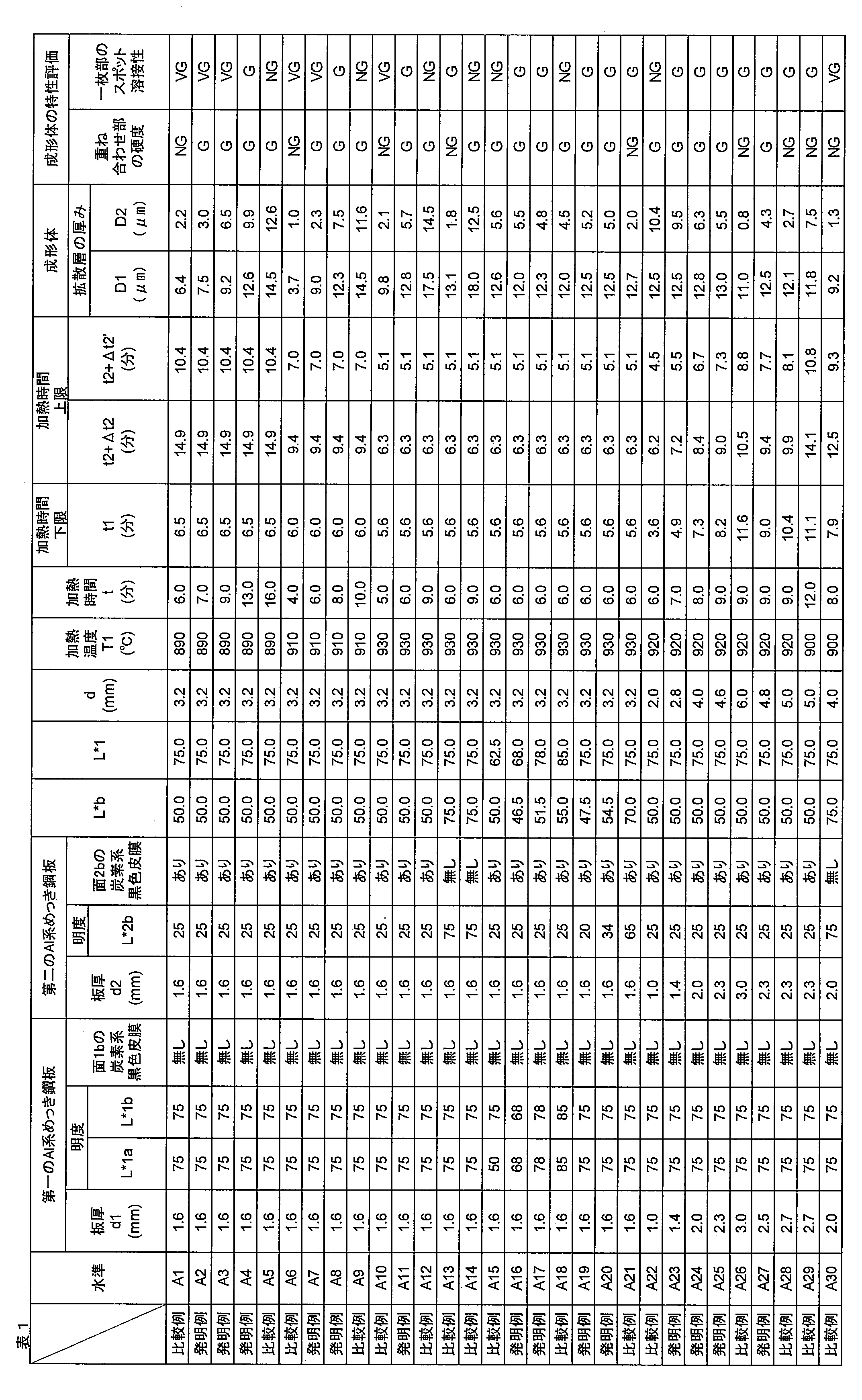
発明例であるA2~A4、A7、A8、A11、A16、A17、A19、A20、A23~A25、A27は、板厚が本発明の範囲内にあり、炭素系黒色皮膜を有し、加熱温度と加熱時間の関係が式(a)~式(f)を満足するため、ホットスタンプ後の重ね合わせ部の硬度、スポット溶接性は良好であった。特に、発明例のA2、A3、A7は、加熱時間が式(d)、(e)、及び、好ましい式(f’)を満足するため、スポット溶接性がVGとより好ましい評価結果が得られる。
比較例であるA1、A5、A6、A9、A10、A12は、加熱温度と時間の関係が式(a)~(f)を満足しないため、重ね合わせ部の硬度又はスポット溶接性が不良であった。比較例であるA13、A14、A30は、炭素系黒色皮膜を有さないため、昇温速度が遅く重ね合わせ部の硬度が不良であった。比較例であるA15は、L*1の値が、(L*b+20)を超えなかったため、一枚部の過加熱が抑制されずスポット溶接性が不良あった。比較例であるA18は、L*1の値が80を超えるため、スポット溶接性が不良であった。比較例であるA21では、明度L*bの値が60を超えるため、重ね合わせ部の硬度が不良であった。比較例であるA22は、第一のAl系めっき鋼板と第二のAl系めっき鋼板の合計板厚が2.5mm未満であるため、過剰な加熱時間となり一枚部のスポット溶接性が不良であった。比較例であるA26、A28、A29は、第一のAl系めっき鋼板と第二のAl系めっき鋼板の合計板厚が4.8mm超であるため、重ね合わせ部の昇温速度が遅く、重ね合わせ部の硬度が不良であった。
(実施例2)
実施例1の水準A16と同様の製造条件にて、第一のAl系めっき鋼板、第二のAl系めっき鋼板を作製し、第二のAl系めっき鋼板のAl系めっき鋼板の上に炭素系黒色皮膜を形成させ、膜厚を15μmにした水準を作製した結果、明度L*2bの値が10、L*bの値が39となった。テープ剥離(テープ:ニチバン株式会社製CT405AP-24)した結果、皮膜の剥離が認められ実用的では無かった。同様の試験にて、A16やA19では剥離は認められなかった。
実施例1の水準A16と同様の製造条件にて、第一のAl系めっき鋼板、第二のAl系めっき鋼板を作製し、第二のAl系めっき鋼板のAl系めっき鋼板の上に炭素系黒色皮膜を形成させ、膜厚を15μmにした水準を作製した結果、明度L*2bの値が10、L*bの値が39となった。テープ剥離(テープ:ニチバン株式会社製CT405AP-24)した結果、皮膜の剥離が認められ実用的では無かった。同様の試験にて、A16やA19では剥離は認められなかった。
(実施例3)
実施例1の水準A3と同様の製造条件にて、第一のAl系めっき鋼板、及び、第二のAl系めっき鋼板を作製し、第二のAl系めっき鋼板のAl系めっき層の上に、炭素系黒色皮膜を形成させた。この時、第二のAl系めっき鋼板のめっき付着量を、片側当たり55g/m2、45g/m2、30g/m2とした水準A31、A32、A33を作成した。
実施例1の水準A3と同様の製造条件にて、第一のAl系めっき鋼板、及び、第二のAl系めっき鋼板を作製し、第二のAl系めっき鋼板のAl系めっき層の上に、炭素系黒色皮膜を形成させた。この時、第二のAl系めっき鋼板のめっき付着量を、片側当たり55g/m2、45g/m2、30g/m2とした水準A31、A32、A33を作成した。
得られた水準A3、A31、A32、A33を、実施例1における水準A3の条件で加熱し、焼入れした重ね合わせホットスタンプ成形体を得た。得られた重ね合わせホットスタンプ成形体から、第二のAl-Fe系合金めっき鋼板を切り出し、実施例1に記載したものと同様の条件でスポット溶接し、第二のAl-Fe系合金めっき鋼板のスポット溶接性を評価した。
その結果、水準A3とA31の評点はVGであり、水準A32とA33の評点はGであった。この理由は、水準A3とA31は、第一のAl系めっき鋼板のめっき付着量W1から、第二のAl系めっき鋼板のめっき付着量W2を差し引いた値|W1-W2|が25g/m2以下と好ましい範囲内であった一方で、水準A32とA33は、第一のAl系めっき鋼板のめっき付着量から、第二のAl系めっき鋼板のめっき付着量を差し引いた値|W1-W2|が35g/m2以上と、上記の好ましい範囲から外れていたためと考えられる。なお、水準A31、A32、A33の重ね合わせ部の硬度、第一のAl-Fe系合金めっき鋼板の一枚部のスポット溶接性は、水準A3と同じく、それぞれ評点G、評点VGであった。
(実施例4)
表2に示す、実施例1と同様の製造条件にて、第一のAl系めっき鋼板と第二のAl系めっき鋼板それぞれの、重ね合わされていないAl系めっき表面に、炭素系黒色皮膜を膜厚0.5~8.0μmで塗装した。本ブランクを表1の加熱温度にてホットスタンプ加熱することで重ね合わせ部の昇温速度を調査し、重ね合わせ部を表1の時間で加熱した後、8秒後に30℃/秒以上の冷速で金型冷却することで重ね合わせホットスタンプ成形体12を得た。重ね合わされていない部分(一枚部)のフランジ部11を2枚切り出し、同種板組みでスポット溶接性を調査した。表2における各水準は、本願発明例をB1~B7として示した。
表2に示す、実施例1と同様の製造条件にて、第一のAl系めっき鋼板と第二のAl系めっき鋼板それぞれの、重ね合わされていないAl系めっき表面に、炭素系黒色皮膜を膜厚0.5~8.0μmで塗装した。本ブランクを表1の加熱温度にてホットスタンプ加熱することで重ね合わせ部の昇温速度を調査し、重ね合わせ部を表1の時間で加熱した後、8秒後に30℃/秒以上の冷速で金型冷却することで重ね合わせホットスタンプ成形体12を得た。重ね合わされていない部分(一枚部)のフランジ部11を2枚切り出し、同種板組みでスポット溶接性を調査した。表2における各水準は、本願発明例をB1~B7として示した。

表1の比較例の水準A1では同じ板厚、加熱温度、加熱時間で重ね合わせ部の硬度が不良だったが、発明例B1では、重ね合わせ部の硬度が良好な結果を示した。発明例B4も重ね合わせ部の硬度、一枚部のスポット溶接性は良好であるが、B2、B3は、表1の比較例の水準A10では同じ板厚、加熱温度、加熱時間で重ね合わせ部の硬度が不良だったが、発明例B2~B4では、重ね合わせ部の硬度が良好な結果を示した。
以上、添付図面を参照しながら本発明の好適な実施形態について詳細に説明したが、本発明はかかる例に限定されない。本発明の属する技術の分野における通常の知識を有する者であれば、特許請求の範囲に記載された技術的思想の範疇内において、各種の変更例又は修正例に想到し得ることは明らかであり、これらについても、当然に本発明の技術的範囲に属するものと了解される。
なお、本出願は、2022年5月19日付で出願した、以下のような要旨を有する発明を基礎として、優先権を主張するものである。
[a]
重ね合わせブランクを加熱炉で加熱する重ね合わせブランク加熱工程と、
加熱された前記重ね合わせブランクを、前記加熱炉から搬出してプレス装置に搬送する加熱ブランク搬送工程と、
前記加熱された重ね合わせブランクを前記プレス装置に設けられた金型でプレス加工して、重ね合わせホットスタンプ成形体を得るホットスタンプ工程と、
からなる、重ね合わせホットスタンプ成形体の製造方法であって、
前記重ね合わせブランクは、板厚d1(mm)の第一の鋼板と、前記第一の鋼板上に重ね合わされて溶接された、少なくとも一枚の、前記第一の鋼板よりも面積の小さな板厚d2(mm)の第二の鋼板と、からなり、
前記第一の鋼板及び前記第二の鋼板は、それぞれ鋼板の両面にAl系めっき層を有するAl系めっき鋼板であり、
前記第二の鋼板は、前記第一の鋼板と接しない側の前記Al系めっき層の少なくとも一部の上層として、炭素系黒色皮膜を有し、
前記第一の鋼板の表面のJIS Z 8781-4に定める明度L*について、前記第二の鋼板と接する側の表面においてL*1aとし、前記第二の鋼板と接しない側の表面においてL*1bとし、前記第二の鋼板の表面のJIS Z 8781-4に定める明度L*について、前記第一の鋼板と接しない側の表面においてL*2bとしたときに、
L*1bとL*2bの平均値L*bは、40以上60以下であり、かつ、L*1aとL*1bの平均値L*1は、(L*b+20)以上80以下であり、
前記第一の鋼板と前記第二の鋼板とが重ね合わされた部分の合計板厚d=(d1+d2)は、2.5mm以上5.0mm以下であり、
前記重ね合わせブランク加熱工程において、前記重ね合わせブランクを、温度T1(℃)の加熱炉で、時間t(分)で加熱する際、前記加熱炉において、加熱時間t(分)、及び、加熱温度T1(℃)で定義される座標平面において、下記式(1)~(9)のグラフで定まる時間t1(分)以上、(t2+△t2)(分)以下の加熱時間で、前記重ね合わせブランクを加熱する、重ね合わせホットスタンプ成形体の製造方法。
ここで、T1、t1、t2、△t2は下記で示される。
T1=A1・t12+B1・t1+C1 ・・・式(1)
A1=-0.3645d5+6.343d4-43.822d3
+151.71d2-268.89d+205.68 ・・・式(2)
B1=+2.9347d5-47.313d4+298.84d3
-936.35d2+1518.1d-1197.6 ・・・式(3)
C1=1381.57 ・・・式(4)
T1=A2・t22+B2・t2+C2 ・・・式(5)
A2=-0.4367d15+7.3789d14-49.107d13
+161.95d12-269.2d1+188.97 ・・・式(6)
B2=+1.8594d15-31.034d14+204.62d13
-675.11d12+1159.2d1-964.59 ・・・式(7)
C2=1367.39 ・・・式(8)
△t2=2.6960×10¹³×e(-0.03205×T1) ・・・式(9)
[b]
前記△t2が、下記式(10)を満足する、[a]に記載の重ね合わせホットスタンプ成形体の製造方法。
△t2=1.498×10¹³×e(-0.03198×T1) ・・・式(10)
[c]
重ね合わせブランクを加熱炉で加熱する重ね合わせブランク加熱工程と、
加熱された前記重ね合わせブランクを、前記加熱炉から搬出してプレス装置に搬送する加熱ブランク搬送工程と、
前記加熱された重ね合わせブランクを前記プレス装置に設けられた金型でプレス加工して、重ね合わせホットスタンプ成形体を得るホットスタンプ工程と、
からなる、重ね合わせホットスタンプ成形体の製造方法であって、
前記重ね合わせブランクは、板厚d1(mm)の第一の鋼板と、前記第一の鋼板上に重ね合わされて溶接された、少なくとも一枚の、前記第一の鋼板よりも面積の小さな板厚d2(mm)の第二の鋼板と、からなり、
前記第一の鋼板及び前記第二の鋼板は、それぞれ鋼板の両面にAl系めっき層を有するAl系めっき鋼板であり、
前記第一の鋼板は、前記第二の鋼板と接しない側の前記Alめっき層の少なくとも一部の上層として、炭素系黒色皮膜を有し、
前記第二の鋼板は、前記第一の鋼板と接しない側の前記Al系めっき層の少なくとも一部の上層として、炭素系黒色皮膜を有し、
前記第一の鋼板の表面のJIS Z 8781-4に定める明度L*について、前記第二の鋼板と接する側の表面においてL*1aとし、前記第二の鋼板と接しない側の表面においてL*1bとし、前記第二の鋼板の表面のJIS Z 8781-4に定める明度L*について、前記第一の鋼板と接しない側の表面においてL*2bとしたときに、
L*1bとL*2bの平均値L*bは、20以上40未満であり、かつ、L*1aとL*1bの平均値L*1は、(L*b+20)以上60以下であり、
前記第一の鋼板と前記第二の鋼板とが重ね合わされた部分の合計板厚d=(d1+d2)は、2.5mm以上5.0mm以下であり、
前記重ね合わせブランク加熱工程において、前記重ね合わせブランクを、温度T3(℃)の加熱炉で、時間t(分)で加熱する際、前記加熱炉において、加熱時間t(分)、及び、加熱温度T3(℃)で定義される座標平面において、下記式(11)~(20)のグラフで定まる時間t3(分)以上、(t4+△t4)(分)以下の加熱時間で、前記重ね合わせブランクを加熱する、重ね合わせホットスタンプ成形体の製造方法。
ここで、T3、t3、t4、△t4は下記で示される。
T3=A3・t32+B3・t3+C3 ・・・式(11)
A3=-0.5693d5+9.8168d4-67.002d3
+228.11d2-394.85d+291.77 ・・・式(12)
B3=+3.0472d5-49.829d4+320.43d3
-1026.6d2+1706.7d-1374.3 ・・・式(13)
C3=1394.21 ・・・式(14)
T3=A4・t42+B4・t4+C4 ・・・式(15)
A4=-0.3645d15+6.343d14-43.822d13
+151.71d12-268.89d1+205.68 ・・・式(16)
B4=+2.9347d15-47.313d14+298.84d13
-936.35d12+1518.1d1-1197.6 ・・・式(17)
C4=1381.57 ・・・式(18)
△t4=2.6960×10¹³×e(-0.03205×T3) ・・・式(19)
[d]
前記△t4が、下記式(20)を満足する、請求項3に記載の重ね合わせホットスタンプ成形体の製造方法。
△t4=1.498×10¹³×e(-0.03198×T3) ・・・式(20)
1 第一のAl系めっき鋼板
1a 第一のAl系めっき鋼板の中の、第二のAl系めっき鋼板と接する面
1b 第一のAl系めっき鋼板の中の、第二のAl系めっき鋼板と接しない面
2 第二のAl系めっき鋼板
2a 第二のAl系めっき鋼板の中の、第一のAl系めっき鋼板と接する面
2b 第二の鋼板の中の、第一のAl系めっき鋼板と接しない面
3 溶接部
4 ホットスタンプ用重ね合わせブランク
4a ホットスタンプ用重ね合わせブランクの中の、重ね合わせ部
4b ホットスタンプ用重ね合わせブランクの中の、一枚部
5 ホットスタンプのための加熱炉
6 ホットスタンプのためのプレス金型
7 頭頂部
8 頭頂部側の曲げ部
9 フランジ側の曲げ部
10 縦壁部
11 フランジ部
12 重ね合わせホットスタンプ成形体
13 Al系めっき鋼板の片側の表面
14 Al系めっき層
15 母材鋼板
16 Al系めっき層の上層に炭素系黒色皮膜を有するAl系めっき鋼板の片側の表面
17 炭素系黒色皮膜
18 Al-Fe系合金めっき鋼板の片側の表面
19 Al-Fe系合金めっき層
20 拡散層
21 母材鋼板
Claims (4)
- 板厚d1の第一のAl系めっき鋼板と、
前記第一のAl系めっき鋼板上に重ね合わされて溶接された、前記第一のAl系めっき鋼板よりも面積の小さく、かつ、前記第一のAl系めっき鋼板と接しない側の前記Al系めっき鋼板の表面に炭素系黒色被膜を有する、板厚d2の第二のAl系めっき鋼板と、
を備えたホットスタンプ用重ね合わせブランクを、温度T1の加熱炉にて加熱する加熱方法であって、
前記ホットスタンプ用重ね合わせブランクが、下記式(a)~式(c)を満足し、
加熱時間をt1以上、かつ、t2+△t2以下とする、ホットスタンプ用重ね合わせブランクの加熱方法。
ここで、T1は加熱炉の温度であり、t1は下記式(d)の2次方程式の解のうち小さい方の値であり、t2は下記式(e)の2次方程式の解のうち小さい方の値であり、△t2は下記式(f)であり、d、d1及びd2の単位はmmとし、T1の単位は℃とし、t1、t2及び△t2の単位は分とする。
40≦L*b≦60 ・・・式(a)
(L*b+20)≦L*1≦80 ・・・式(b)
2.5≦d≦4.8 ・・・式(c)
T1=A1・t12+B1・t1+C1 ・・・式(d)
T1=A2・t22+B2・t2+C2 ・・・式(e)
△t2=2.6960×10¹³×e(-0.03205×T1) ・・・式(f)
ただし、L*b、L*1、L*1a、L*1b、L*2b、A1、B1、C1、A2、B2及びC2は、下記とする。
L*b=0.5×(L*1b+L*2b) ・・・式(a-1)
L*1=0.5×(L*1a+L*1b) ・・・式(b-1)
d=d1+d2 ・・・式(c-1)
L*1a:第一の鋼板の第二の鋼板と接する側の表面の明度L*
L*1b:第一の鋼板の第二の鋼板と接しない側の表面の明度L*
L*2b:第二の鋼板の第一の鋼板と接しない側の表面の明度L*
A1=-0.3645d5+6.343d4-43.822d3
+151.71d2-268.89d+205.68 ・・・式(d-1)
B1=2.9347d5-47.313d4+298.84d3
-936.35d2+1518.1d-1197.6 ・・・式(d-2)
C1=1381.57 ・・・式(d-3)
A2=-0.4367d15+7.3789d14-49.107d13
+161.95d12-269.2d1+188.97 ・・・式(e-1)
B2=1.8594d15-31.034d14+204.62d13
-675.11d12+1159.2d1-964.59 ・・・式(e-2)
C2=1367.39 ・・・式(e-3) - 前記加熱時間を、t2+△t2’以下とする、請求項1に記載のホットスタンプ用重ね合わせブランクの加熱方法。
ここで、△t2’は下記式(f’)であり、その単位は分である。
△t2’=1.498×10¹³×e(-0.03198×T1) ・・・式(f’) - 板厚d1の第一のAl系めっき鋼板と、
前記第一のAl系めっき鋼板上に重ね合わされて溶接された、前記第一のAl系めっき鋼板よりも面積の小さく、かつ、前記第一のAl系めっき鋼板と接しない側の前記Al系めっき鋼板の表層に炭素系黒色被膜を有する、板厚d2の第二のAl系めっき鋼板と、
を備えたホットスタンプ用重ね合わせブランクを、温度T3の加熱炉にて加熱する加熱方法であって、
前記第一のAl系めっき鋼板は、前記第二のAl系めっき鋼板と接しない側の表面に炭素系黒色皮膜を有し、
前記ホットスタンプ用重ね合わせブランクが、下記式(A)~式(C)を満足し、
加熱時間をt3以上、かつ、t4+△t4以下とする、ホットスタンプ用重ね合わせブランクの加熱方法。
ここで、T3は加熱炉の温度であり、t3は下記式(D)の2次方程式の解のうち小さい方の値であり、t4は下記式(E)の2次方程式の解のうち小さい方の値であり、△t4は下記式(F)であり、d、d1及びd2の単位はmmとし、T3の単位は℃とし、t3、t4及び△t4の単位は分とする。
20≦L*b<40 ・・・式(A)
(L*b+20)≦L*1≦60 ・・・式(B)
2.5≦d≦4.8 ・・・式(C)
T3=A3・t32+B3・t3+C3 ・・・式(D)
T3=A4・t42+B4・t4+C4 ・・・式(E)
△t4=2.6960×10¹³×e(-0.03205×T3) ・・・式(F)
ただし、L*b、L*1、L*1a、L*1b、L*2b、A3、B3、C3、A4、B4及びC4は、下記とする。
L*b=0.5×(L*1b+L*2b) ・・・式(A-1)
L*1=0.5×(L*1a+L*1b) ・・・式(B-1)
d=d1+d2 ・・・式(C-1)
L*1a:第一の鋼板の第二の鋼板と接する側の表面の明度L*
L*1b:第一の鋼板の第二の鋼板と接しない側の表面の明度L*
L*2b:第二の鋼板の第一の鋼板と接しない側の表面の明度L*
A3=-0.5693d5+9.8168d4-67.002d3
+228.11d2-394.85d+291.77 ・・・式(D-1)
B3=3.0472d5-49.829d4+320.43d3
-1026.6d2+1706.7d-1374.3 ・・・式(D-2)
C3=1394.21 ・・・式(D-3)
A4=-0.3645d15+6.343d14-43.822d13
+151.71d12-268.89d1+205.68 ・・・式(E-1)
B4=2.9347d15-47.313d14+298.84d13
-936.35d12+1518.1d1-1197.6 ・・・式(E-2)
C4=1381.57 ・・・式(E-3) - 前記加熱時間を、t4+△t4’以下とする、請求項3に記載のホットスタンプ用重ね合わせブランクの加熱方法。
ここで、△t4’は下記式(F’)であり、その単位は分である。
△t4’=1.498×10¹³×e(-0.03198×T3) ・・・式(F’)
Priority Applications (1)
| Application Number | Priority Date | Filing Date | Title |
|---|---|---|---|
| JP2023546358A JP7425392B1 (ja) | 2022-05-19 | 2023-05-19 | 重ね合わせホットスタンプ成形体の製造方法 |
Applications Claiming Priority (2)
| Application Number | Priority Date | Filing Date | Title |
|---|---|---|---|
| JP2022082169 | 2022-05-19 | ||
| JP2022-082169 | 2022-05-19 |
Publications (1)
| Publication Number | Publication Date |
|---|---|
| WO2023224123A1 true WO2023224123A1 (ja) | 2023-11-23 |
Family
ID=88835267
Family Applications (1)
| Application Number | Title | Priority Date | Filing Date |
|---|---|---|---|
| PCT/JP2023/018803 WO2023224123A1 (ja) | 2022-05-19 | 2023-05-19 | 重ね合わせホットスタンプ成形体の製造方法 |
Country Status (2)
| Country | Link |
|---|---|
| JP (1) | JP7425392B1 (ja) |
| WO (1) | WO2023224123A1 (ja) |
Citations (4)
| Publication number | Priority date | Publication date | Assignee | Title |
|---|---|---|---|---|
| WO2010005121A1 (ja) * | 2008-07-11 | 2010-01-14 | 新日本製鐵株式会社 | 急速加熱ホットプレス用アルミめっき鋼板、その製造方法、及びこれを用いた急速加熱ホットプレス方法 |
| JP2011149084A (ja) * | 2010-01-25 | 2011-08-04 | Nippon Steel Corp | 昇温特性に優れた熱間プレス用Alめっき鋼板及びその製造方法 |
| JP2017189930A (ja) * | 2016-04-14 | 2017-10-19 | 新日鐵住金株式会社 | 黒色塗装亜鉛系めっき鋼板及びその製造方法 |
| WO2019194308A1 (ja) * | 2018-04-06 | 2019-10-10 | 日本製鉄株式会社 | ホットスタンプ用重ね合わせブランク、重ね合わせホットスタンプ成形体の製造方法、及び、重ね合わせホットスタンプ成形体 |
-
2023
- 2023-05-19 WO PCT/JP2023/018803 patent/WO2023224123A1/ja unknown
- 2023-05-19 JP JP2023546358A patent/JP7425392B1/ja active Active
Patent Citations (4)
| Publication number | Priority date | Publication date | Assignee | Title |
|---|---|---|---|---|
| WO2010005121A1 (ja) * | 2008-07-11 | 2010-01-14 | 新日本製鐵株式会社 | 急速加熱ホットプレス用アルミめっき鋼板、その製造方法、及びこれを用いた急速加熱ホットプレス方法 |
| JP2011149084A (ja) * | 2010-01-25 | 2011-08-04 | Nippon Steel Corp | 昇温特性に優れた熱間プレス用Alめっき鋼板及びその製造方法 |
| JP2017189930A (ja) * | 2016-04-14 | 2017-10-19 | 新日鐵住金株式会社 | 黒色塗装亜鉛系めっき鋼板及びその製造方法 |
| WO2019194308A1 (ja) * | 2018-04-06 | 2019-10-10 | 日本製鉄株式会社 | ホットスタンプ用重ね合わせブランク、重ね合わせホットスタンプ成形体の製造方法、及び、重ね合わせホットスタンプ成形体 |
Also Published As
| Publication number | Publication date |
|---|---|
| JP7425392B1 (ja) | 2024-01-31 |
| JPWO2023224123A1 (ja) | 2023-11-23 |
Similar Documents
| Publication | Publication Date | Title |
|---|---|---|
| KR102354183B1 (ko) | 핫 스탬프용 중첩 블랭크, 중첩 핫 스탬프 성형체의 제조 방법, 및 중첩 핫 스탬프 성형체 | |
| CN100370054C (zh) | 镀有铝合金体系的高强度钢板以及具有优异的耐热性和喷漆后耐腐蚀性的高强度汽车零件 | |
| JP4724780B2 (ja) | 急速加熱ホットプレス用アルミめっき鋼板、その製造方法、及びこれを用いた急速加熱ホットプレス方法 | |
| US11535916B2 (en) | Aluminum-based plated steel sheet, method of manufacturing aluminum-based plated steel sheet, and method of manufacturing component for vehicle | |
| US11530474B2 (en) | Fe—Al-based plated hot-stamped member and manufacturing method of Fe—Al-based plated hot-stamped member | |
| JP2006051543A (ja) | 冷延、熱延鋼板もしくはAl系、Zn系めっき鋼板を使用した高強度自動車部材の熱間プレス方法および熱間プレス部品 | |
| KR20170118866A (ko) | 열간 프레스 부재 및 그 제조 방법 | |
| JP7307307B2 (ja) | 突合せ溶接用アルミニウムめっき鋼板、突合せ溶接部材及び熱間プレス成形品 | |
| JP6525124B1 (ja) | アルミ系めっき鋼板、アルミ系めっき鋼板の製造方法及び自動車用部品の製造方法 | |
| US11920243B2 (en) | Method for manufacturing a sheet metal component from a flat steel product provided with a corrosion protection coating | |
| JP7477753B2 (ja) | 重ね合わせブランク、および、それを用いたホットスタンプ成形体の製造方法 | |
| JP7425392B1 (ja) | 重ね合わせホットスタンプ成形体の製造方法 | |
| JP7425391B1 (ja) | ホットスタンプ用重ね合わせブランク、及び、重ね合わせホットスタンプ成形体 | |
| JP7226644B2 (ja) | 重ね合わせホットスタンプ成形体の製造方法及び重ね合わせホットスタンプ成形体 | |
| US20240133014A1 (en) | Method for Manufacturing a Sheet Metal Component from a Flat Steel Product Provided With a Corrosion Protection Coating | |
| US20230047998A1 (en) | Steel component comprising an anti-corrosion layer containing manganese | |
| KR102172010B1 (ko) | 도금 강판, 도금 강판 코일, 열간 프레스 성형품의 제조 방법, 및 자동차 부품 | |
| US20230407449A1 (en) | Hot-pressed member, steel sheet for hot pressing, and method for manufacturing hot-pressed member | |
| WO2023074114A1 (ja) | 熱間プレス部材 | |
| WO2024089931A1 (ja) | 熱間プレス部材および熱間プレス用鋼板 | |
| WO2023074115A1 (ja) | 熱間プレス部材 |
Legal Events
| Date | Code | Title | Description |
|---|---|---|---|
| ENP | Entry into the national phase |
Ref document number: 2023546358 Country of ref document: JP Kind code of ref document: A |
|
| 121 | Ep: the epo has been informed by wipo that ep was designated in this application |
Ref document number: 23807724 Country of ref document: EP Kind code of ref document: A1 |