WO2023223760A1 - 制御装置、制御方法、制御プログラム、及びシステム - Google Patents
制御装置、制御方法、制御プログラム、及びシステム Download PDFInfo
- Publication number
- WO2023223760A1 WO2023223760A1 PCT/JP2023/015649 JP2023015649W WO2023223760A1 WO 2023223760 A1 WO2023223760 A1 WO 2023223760A1 JP 2023015649 W JP2023015649 W JP 2023015649W WO 2023223760 A1 WO2023223760 A1 WO 2023223760A1
- Authority
- WO
- WIPO (PCT)
- Prior art keywords
- image
- content
- control device
- information
- projection
- Prior art date
- Legal status (The legal status is an assumption and is not a legal conclusion. Google has not performed a legal analysis and makes no representation as to the accuracy of the status listed.)
- Ceased
Links
Images










Classifications
-
- H—ELECTRICITY
- H04—ELECTRIC COMMUNICATION TECHNIQUE
- H04N—PICTORIAL COMMUNICATION, e.g. TELEVISION
- H04N9/00—Details of colour television systems
- H04N9/12—Picture reproducers
- H04N9/31—Projection devices for colour picture display, e.g. using electronic spatial light modulators [ESLM]
- H04N9/3102—Projection devices for colour picture display, e.g. using electronic spatial light modulators [ESLM] using two-dimensional electronic spatial light modulators
- H04N9/3105—Projection devices for colour picture display, e.g. using electronic spatial light modulators [ESLM] using two-dimensional electronic spatial light modulators for displaying all colours simultaneously, e.g. by using two or more electronic spatial light modulators
-
- G—PHYSICS
- G06—COMPUTING OR CALCULATING; COUNTING
- G06F—ELECTRIC DIGITAL DATA PROCESSING
- G06F3/00—Input arrangements for transferring data to be processed into a form capable of being handled by the computer; Output arrangements for transferring data from processing unit to output unit, e.g. interface arrangements
- G06F3/01—Input arrangements or combined input and output arrangements for interaction between user and computer
- G06F3/048—Interaction techniques based on graphical user interfaces [GUI]
- G06F3/0481—Interaction techniques based on graphical user interfaces [GUI] based on specific properties of the displayed interaction object or a metaphor-based environment, e.g. interaction with desktop elements like windows or icons, or assisted by a cursor's changing behaviour or appearance
-
- G—PHYSICS
- G06—COMPUTING OR CALCULATING; COUNTING
- G06F—ELECTRIC DIGITAL DATA PROCESSING
- G06F3/00—Input arrangements for transferring data to be processed into a form capable of being handled by the computer; Output arrangements for transferring data from processing unit to output unit, e.g. interface arrangements
- G06F3/14—Digital output to display device ; Cooperation and interconnection of the display device with other functional units
-
- G—PHYSICS
- G06—COMPUTING OR CALCULATING; COUNTING
- G06T—IMAGE DATA PROCESSING OR GENERATION, IN GENERAL
- G06T19/00—Manipulating three-dimensional [3D] models or images for computer graphics
-
- H—ELECTRICITY
- H04—ELECTRIC COMMUNICATION TECHNIQUE
- H04N—PICTORIAL COMMUNICATION, e.g. TELEVISION
- H04N5/00—Details of television systems
- H04N5/74—Projection arrangements for image reproduction, e.g. using eidophor
-
- H—ELECTRICITY
- H04—ELECTRIC COMMUNICATION TECHNIQUE
- H04N—PICTORIAL COMMUNICATION, e.g. TELEVISION
- H04N9/00—Details of colour television systems
- H04N9/12—Picture reproducers
- H04N9/31—Projection devices for colour picture display, e.g. using electronic spatial light modulators [ESLM]
- H04N9/3141—Constructional details thereof
- H04N9/3147—Multi-projection systems
-
- H—ELECTRICITY
- H04—ELECTRIC COMMUNICATION TECHNIQUE
- H04N—PICTORIAL COMMUNICATION, e.g. TELEVISION
- H04N9/00—Details of colour television systems
- H04N9/12—Picture reproducers
- H04N9/31—Projection devices for colour picture display, e.g. using electronic spatial light modulators [ESLM]
- H04N9/3179—Video signal processing therefor
Definitions
- the present invention relates to a control device, a control method, a control program, and a system.
- Patent Document 1 discloses a method for augmented reality in which a real world image including a marker is generated, the marker is detected from the real world image, an object image corresponding to the detected marker is combined with the real world image, It is stated that the combined image will be displayed.
- Patent Document 2 discloses that in an image taken of a real space including a display area where no products are displayed, a product image is displayed superimposed on the display area in the real space, and the product image superimposed in the real space is In response, when a user performs a first action, an information processing apparatus is described that performs processing for ordering a product corresponding to the product image.
- Patent Document 3 discloses that when it is recognized that a specific object has entered the frame within the screen of the display unit, and the number of frame-in recognitions matches a preset number of recognitions, a predetermined display is displayed according to the number of recognitions. An image processing device that performs this is described.
- Patent Document 4 discloses a method for capturing an image of a seal including a name and a marker placed around the name, extracting a seal image from the captured image, extracting a marker included in the seal from the seal image, and extracting the image.
- a mobile terminal device is described that selects and generates a generated image associated with a marker from a generated image database.
- One embodiment of the technology of the present disclosure provides a control device, a control method, a control program, and a system that can change the visibility of an image associated with content depending on the playback status of the content. .
- a control device comprising a processor, The above processor is projecting a second image including the first image associated with the content from a projection device; Obtain playback information regarding playback of the above content by the information terminal, changing the display mode of the first image in the second image based on the reproduction information; Control device.
- Changing the display mode of the first image is a process of changing the visibility of the first image, Control device.
- the control device according to any one of (1) to (4),
- the playback information is information regarding the number of playbacks of the content, Control device.
- the control device includes information indicating the number of times the content has been played by one or more information terminals; Control device.
- the control device includes information indicating the number of information terminals that have played the content; Control device.
- the control device according to any one of (5) to (7),
- the information regarding the number of playbacks of the content includes information indicating the number of information terminals that are simultaneously playing the content; Control device.
- the control device according to any one of (5) to (8),
- the second image includes an image representing information regarding the number of plays of the content, Control device.
- the control device according to any one of (1) to (9),
- the first image includes a plurality of first images that can be played back by different information terminals,
- the processor obtains the reproduction information regarding the plurality of first images. Control device.
- the controller's processor projecting a second image including the first image associated with the content from a projection device; Obtain playback information regarding playback of the above content by the information terminal, changing the display mode of the first image in the second image based on the reproduction information; Control method.
- control device it is possible to provide a control device, a control method, a control program, and a system that can change the visibility of an image associated with content depending on the playback status of the content.
- FIG. 1 is a diagram illustrating an example of a system 100 according to an embodiment.
- 1 is a diagram showing an example of the configuration of a projection device 10.
- FIG. 2 is a schematic diagram showing an example of the internal configuration of the projection section 1.
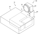
- FIG. 1 is a diagram showing an example of an external configuration of a projection device 10.
- FIG. 5 is a schematic partial cross-sectional view of the optical unit 106 of the projection device 10 shown in FIG. 4.
- FIG. 3 is a diagram showing an example of the hardware configuration of an information terminal 80.
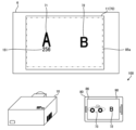
- FIG. FIG. 3 is a diagram illustrating an example of image projection and playback of augmented reality content.
- 4 is a diagram showing an example of processing by the control device 4.
- FIG. 7 is a diagram showing a first example of changing the display mode of a marker image 71.
- FIG. 7 is a diagram illustrating a second example of changing the display mode of a marker image 71.
- FIG. 7 is a diagram illustrating a third example of changing the display mode of a marker image 71.
- FIG. 7 is a diagram showing a fourth example of changing the display mode of a marker image 71;
- FIG. 7 is a diagram showing a fifth example of changing the display mode of a marker image 71;
- FIG. 7 is a diagram showing a sixth example of changing the display mode of a marker image 71;
- 7 is a diagram illustrating an example of a display of an image representing information regarding the number of reproductions of a content image 73.
- FIG. FIG. 7 is a diagram illustrating an example of a correspondence table for changing the display mode.
- FIG. 7 is a diagram illustrating an example of a correspondence table for changing the display mode.
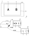
- FIG. 6 is a diagram illustrating an example of a plurality of first images on different information terminals that can play content.
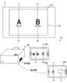
- FIG. 3 is a diagram illustrating an example of a display of attributes of an information terminal that can be reproduced.
- 3 is a schematic diagram showing another external configuration of the projection device 10.
- FIG. 20 is a schematic cross-sectional view of the optical unit 106 of the projection device 10 shown in FIG. 19.
- FIG. 3 is a diagram showing a modification of the system 100.
- FIG. 1 is a diagram showing an example of a hardware configuration of an information terminal 110.
- FIG. 1 is a diagram illustrating an example of a system 100 according to an embodiment.
- the system 100 includes a projection device 10 and an information terminal 80.
- the control device in the present invention is applied to the projection device 10, for example.
- the projection device 10 is a projection device capable of projecting onto the projection target 6.
- the projection object 6 is an object such as a screen or a wall that has a projection surface on which a projected image is displayed by the projection device 10.
- the projection surface of the projection object 6 is a rectangular plane. It is assumed that the top, bottom, right and left of the projection target 6 in FIG. 1 are the top, bottom, left and right of the actual projection target 6.
- a projection range 11 illustrated by a dashed line is an area of the projection target 6 that is irradiated with projection light by the projection device 10.
- the projection range 11 is part or all of the projectable range that can be projected by the projection device 10 .
- the projection range 11 is rectangular.
- the information terminal 80 is an information terminal, such as a smartphone or a tablet terminal, that has an imaging section (for example, the imaging module 85 in FIG. 6) and a display section 86.
- an imaging section for example, the imaging module 85 in FIG. 6
- the information terminal 80 superimposes predetermined augmented reality (AR) content on the captured image.
- An application for displaying a superimposed image on the display unit 86 is stored (installed).
- AR augmented reality
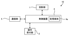
- FIG. 2 is a diagram showing an example of the configuration of the projection device 10.
- the projection device 10 includes, for example, a projection section 1, a control device 4, and an operation reception section 2.
- the projection device 10 may further include a communication section 5.
- the projection unit 1 is configured by, for example, a liquid crystal projector or a projector using LCOS (Liquid Crystal On Silicon). The following description will be made assuming that the projection unit 1 is a liquid crystal projector.
- LCOS Liquid Crystal On Silicon
- the control device 4 is an example of the control device of the present invention.
- the control device 4 controls projection by the projection device 10 .
- the control device 4 includes a control section composed of various processors, a communication interface (not shown) for communicating with each section, and a storage medium such as a hard disk, SSD (Solid State Drive), or ROM (Read Only Memory). 4a, and centrally controls the projection unit 1.
- Various processors in the control unit of the control device 4 include a CPU (Central Processing Unit), which is a general-purpose processor that executes programs and performs various processes, and an FPGA (Field Programmable Gate Array), whose circuit configurations are changed after manufacturing.
- CPU Central Processing Unit
- FPGA Field Programmable Gate Array
- a dedicated electric circuit which is a processor with a circuit configuration, etc. is included.
- the structure of these various processors is an electric circuit that combines circuit elements such as semiconductor elements.
- the control unit of the control device 4 may be configured with one of various processors, or a combination of two or more processors of the same type or different types (for example, a combination of multiple FPGAs or a combination of a CPU and an FPGA). It may be composed of.
- the operation reception unit 2 detects instructions from the user (user instructions) by accepting various operations from the user.
- the operation reception section 2 may be a button, a key, a joystick, etc. provided on the control device 4, or may be a reception section or the like that receives a signal from a remote controller that remotely controls the control device 4.
- the communication unit 5 is a communication interface that can communicate with other devices.
- the communication unit 5 may be a wired communication interface that performs wired communication, or may be a wireless communication interface that performs wireless communication.
- the projection unit 1, the control device 4, the operation reception unit 2, and the communication unit 5 are realized by, for example, one device (see, for example, FIGS. 4 and 5).
- the projection unit 1, the control device 4, the operation reception unit 2, and the communication unit 5 may be realized by a plurality of devices that can cooperate by communicating with each other.
- FIG. 3 is a schematic diagram showing an example of the internal configuration of the projection section 1.
- the projection section 1 of the projection apparatus 10 shown in FIG. 2 includes a light source 21, a light modulation section 22, a projection optical system 23, and a control circuit 24, as shown in FIG.
- the light source 21 includes a light emitting element such as a laser or an LED (Light Emitting Diode), and emits, for example, white light.
- the light modulation unit 22 modulates each color light emitted from the light source 21 and separated into three colors of red, blue, and green by a color separation mechanism (not shown) based on image information, and outputs each color image. It is composed of a liquid crystal panel (light modulation element) and a dichroic prism that mixes each color image emitted from the three liquid crystal panels and emits it in the same direction. Red, blue, and green filters may be mounted on each of these three liquid crystal panels, and the white light emitted from the light source 21 may be modulated by each liquid crystal panel to emit each color image.
- the projection optical system 23 receives light from the light source 21 and the light modulation section 22, and is configured by, for example, a relay optical system including at least one lens. The light passing through the projection optical system 23 is projected onto the projection target 6.
- a region of the projection target 6 that is irradiated with light that passes through the entire range of the light modulation section 22 becomes a projectable range that can be projected by the projection section 1.
- the area to which the light actually transmitted from the light modulation section 22 is irradiated becomes the projection range 11 of the projection section 1 .
- the size, position, and shape of a region of the light modulation section 22 through which light passes are changed in the projectable range.
- the control circuit 24 controls the light source 21, the light modulation section 22, and the projection optical system 23 based on the display data input from the control device 4, so that an image based on the display data is displayed on the projection target 6. to be projected.
- the display data input to the control circuit 24 is composed of three pieces: red display data, blue display data, and green display data.
- control circuit 24 expands or reduces the projection range of the projection unit 1 by changing the projection optical system 23 based on commands input from the control device 4. Further, the control device 4 may move the projection range of the projection unit 1 by changing the projection optical system 23 based on a user's operation accepted by the operation reception unit 2.
- the projection device 10 includes a shift mechanism that mechanically or optically moves the projection range of the projection unit 1 while maintaining the image circle of the projection optical system 23.
- the image circle of the projection optical system 23 is an area in which the projection light incident on the projection optical system 23 passes through the projection optical system 23 appropriately in terms of light falloff, color separation, peripheral curvature, and the like.
- the shift mechanism is realized by at least one of an optical system shift mechanism that shifts the optical system and an electronic shift mechanism that shifts the electronic system.
- the optical system shift mechanism is, for example, a mechanism that moves the projection optical system 23 in a direction perpendicular to the optical axis (see, for example, FIGS. 5 and 20), or a mechanism that moves the optical modulator 22 along the optical axis instead of moving the projection optical system 23. This is a mechanism that moves the object in a direction perpendicular to the direction. Further, the optical system shift mechanism may be a mechanism that combines the movement of the projection optical system 23 and the movement of the light modulation section 22.
- the electronic shift mechanism is a mechanism that performs a pseudo projection range shift by changing the range through which light is transmitted in the light modulation section 22.
- the projection device 10 may include a projection direction changing mechanism that moves the projection range together with the image circle of the projection optical system 23.
- the projection direction changing mechanism is a mechanism that changes the projection direction of the projection section 1 by changing the direction of the projection section 1 by mechanical rotation (see, for example, FIG. 20).
- FIG. 4 is a diagram showing an example of the external configuration of the projection device 10.
- FIG. 5 is a schematic partial cross-sectional view of the optical unit 106 of the projection apparatus 10 shown in FIG. 4.
- FIG. 5 shows a cross section taken along the optical path of light emitted from the main body 101 shown in FIG.
- the projection device 10 includes a main body 101 and an optical unit 106 provided to protrude from the main body 101.
- the operation reception section 2, the control device 4, the light source 21, the light modulation section 22, and the control circuit 24 in the projection section 1, and the communication section 5 are provided in the main body section 101.
- the projection optical system 23 in the projection section 1 is provided in the optical unit 106.
- the optical unit 106 includes a first member 102 supported by the main body 101.
- the optical unit 106 may be configured to be detachably attached to the main body portion 101 (in other words, configured to be replaceable).
- the main body portion 101 has a casing 15 in which an opening 15a for passing light is formed in a portion connected to the optical unit 106.
- a light source 21 As shown in FIG. 4, inside the casing 15 of the main body section 101, there is a light source 21 and a light modulation section 22 (which generates an image by spatially modulating the light emitted from the light source 21 based on input image data). (see FIG. 3).
- the light emitted from the light source 21 enters the light modulation section 22 of the light modulation unit 12, is spatially modulated by the light modulation section 22, and is emitted.
- Image G1 becomes visible to the observer.
- the optical unit 106 includes a first member 102 having a hollow portion 2A connected to the inside of the main body 101, a first optical system 121 disposed in the hollow portion 2A, a lens 34, and a first member 102.
- a shift mechanism 105 is provided.
- the first member 102 is a member having a rectangular cross-sectional outer shape, for example, and the opening 2a and the opening 2b are formed in planes parallel to each other.
- the first member 102 is supported by the main body 101 with the opening 2a facing the opening 15a of the main body 101.
- Light emitted from the light modulation section 22 of the light modulation unit 12 of the main body section 101 is incident on the hollow section 2A of the first member 102 through the opening 15a and the opening 2a.
- the direction of incidence of light entering the hollow portion 2A from the main body portion 101 is referred to as a direction X1, the direction opposite to the direction X1 is referred to as a direction X2, and the directions X1 and X2 are collectively referred to as a direction X.
- the direction from the front to the back of the page and the opposite direction are referred to as direction Z.
- the direction from the front to the back of the page is referred to as a direction Z1
- the direction from the back to the front of the page is referred to as a direction Z2.
- the direction perpendicular to the direction X and the direction Z is described as a direction Y, the direction going upward in FIG. .
- the projection device 10 is arranged so that the direction Y2 is the vertical direction.
- the projection optical system 23 shown in FIG. 3 is composed of the first optical system 121 and the lens 34 in the example shown in FIG. FIG. 5 shows the optical axis K of this projection optical system 23.
- the first optical system 121 and the lens 34 are arranged along the optical axis K in this order from the light modulation section 22 side.
- the first optical system 121 includes at least one lens, and guides the light incident on the first member 102 from the main body 101 and traveling in the direction X1 to the lens 34.
- the lens 34 is arranged at the end of the first member 102 in the direction X1 so as to close the opening 2b formed at this end.
- the lens 34 projects the light incident from the first optical system 121 onto the projection target 6.
- the first shift mechanism 105 is a mechanism for moving the optical axis K of the projection optical system (in other words, the optical unit 106) in a direction perpendicular to the optical axis K (direction Y in FIG. 5). Specifically, the first shift mechanism 105 is configured to be able to change the position of the first member 102 in the direction Y with respect to the main body portion 101.
- the first shift mechanism 105 may be one that moves the first member 102 manually or may be one that moves the first member 102 electrically.
- FIG. 5 shows a state in which the first member 102 is moved to the maximum extent in the direction Y1 by the first shift mechanism 105. From the state shown in FIG. 5, the first member 102 is moved in the direction Y2 by the first shift mechanism 105, thereby moving the center of the image formed by the light modulating section 22 (in other words, the center of the display surface) and the optical axis K.
- the image G1 projected onto the projection object 6 can be shifted (translated) in the direction Y2 by changing the relative position with respect to the projection object 6.
- the first shift mechanism 105 may be a mechanism that moves the light modulation section 22 in the Y direction instead of moving the optical unit 106 in the Y direction. Even in this case, the image G1 projected onto the projection object 6 can be moved in the direction Y.
- FIG. 6 is a diagram showing an example of the hardware configuration of the information terminal 80.
- the information terminal 80 shown in FIG. 1 includes a processor 81, a memory 82, a communication interface 83, a user interface 84, and an imaging module 85, as shown in FIG.
- the processor 81, memory 82, communication interface 83, user interface 84, and imaging module 85 are connected by, for example, a bus 89.
- the processor 81 is a circuit that performs signal processing, and is, for example, a CPU that controls the entire information terminal 80. Note that the processor 81 may be realized by other digital circuits such as an FPGA or a DSP (Digital Signal Processor). Further, the processor 81 may be realized by combining a plurality of digital circuits.
- the memory 82 includes, for example, a main memory and an auxiliary memory.
- the main memory is, for example, RAM (Random Access Memory).
- the main memory is used as a work area for the processor 81.
- the auxiliary memory is, for example, nonvolatile memory such as a magnetic disk, optical disk, or flash memory.
- Various programs for operating the information terminal 80 are stored in the auxiliary memory.
- the program stored in the auxiliary memory is loaded into the main memory and executed by the processor 81.
- auxiliary memory may include a portable memory that is removable from the information terminal 80.
- Portable memories include memory cards such as USB (Universal Serial Bus) flash drives and SD (Secure Digital) memory cards, external hard disk drives, and the like.
- the communication interface 83 is a communication interface that communicates with an external device of the information terminal 80. Communication interface 83 is controlled by processor 81 .
- the communication interface 83 may be a wired communication interface that performs wired communication, a wireless communication interface that performs wireless communication, or may include both a wired communication interface and a wireless communication interface.
- the user interface 84 includes, for example, an input device that receives operation input from the user, an output device that outputs information to the user, and the like.
- the input device can be realized by, for example, a pointing device (for example, a mouse), keys (for example, a keyboard), a remote control, or the like.
- the output device can be realized by, for example, a display or a speaker. Further, the input device and the output device may be realized by a touch panel or the like.
- User interface 84 is controlled by processor 81 .
- the display unit 86 of the information terminal 80 shown in FIG. 1 is realized by, for example, a touch panel included in the user interface 84.
- the imaging module 85 is an imaging unit that includes an imaging lens and an imaging element.
- the image sensor for example, a CMOS (complementary metal-oxide-semiconductor) image sensor can be used.
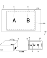
- FIG. 7 is a diagram illustrating an example of image projection and playback of augmented reality content.
- the image 70 is an image to be projected by the projection device 10.
- the image 70 is an image including a marker image 71 representing "A" and a marker image 72 representing "B".
- the marker image 71 is an example of a first image associated with content.
- the image 70 is an example of a second image including a first image associated with content.
- the control device 4 of the projection device 10 outputs image data representing the image 70 to the projection section 1 of the projection device 10. As a result, the image 70 based on the image data is projected onto the projection range 11.
- the imaging range 85a indicates the imaging range by the imaging module 85 of the information terminal 80. That is, by imaging by the imaging module 85 of the information terminal 80, a captured image representing the imaging range 85a of the projection target object 6 is obtained.
- the information terminal 80 When the marker image 71 is included in the captured image obtained by the imaging module 85, the information terminal 80 generates a superimposed image 90 in which the content image 73 is superimposed at the position of the marker image 71 in the captured image together with the captured image.
- An application is stored (installed) for displaying on the display unit 86.
- the content image 73 is an example of content associated with the marker image 71, and in the example of FIG. 7, it is a photographic image or an illustration image of a sports car. Further, in the example of FIG. 7, a range including marker images 71 and 72 of the image 70 is captured by the information terminal 80, and a superimposed image 90 in which the content image 73 is superimposed on the marker image 71 of the image 70 is It is displayed on the display section 86.
- the information terminal 80 displays the superimposed image 90, that is, when the content image 73 is displayed based on the marker image 71, the information terminal 80 transmits reproduction information indicating that the content image 73 has been reproduced to the control device 4 (projection device 10). do.
- the reproduction information is transmitted from the information terminal 80 to the control device 4 via a network such as the Internet or a LAN (Local Area Network).
- the control device 4 After starting projection of the image 70, the control device 4 receives reproduction information about the content image 73 from a plurality of information terminals including the information terminal 80, and controls the display mode of the marker image 71 in the image 70 based on the received reproduction information. change. Changing the display mode of the marker image 71 is, for example, changing the visibility of the marker image 71.
- FIG. 8 is a diagram showing an example of processing by the control device 4.
- the control device 4 executes the process shown in FIG. 8, for example.
- the control device 4 starts projecting the image 70 by controlling the projection device 10 (step S11).
- the control device 4 determines whether reproduction information regarding the content image 73 has been received from an information terminal such as the information terminal 80 (step S12). If the reproduction information has not been received (step S12: No), the control device 4 executes step S12 again.
- step S12 when the reproduction information is received (step S12: Yes), the control device 4 calculates information regarding the number of reproductions of the content image 73 based on the received reproduction information (step S13).
- the information regarding the number of reproductions of the content image 73 is, for example, the number of reproductions of the content image 73.
- the number of times the content image 73 has been played back is the total number of times the content image 73 has been played back by one or more information terminals such as the information terminal 80 . For example, if reproduction information is transmitted every time the content image 73 is reproduced, the control device 4 calculates the number of times the reproduction information is received after step S11 as the number of reproductions of the content image 73 (information regarding the number of reproductions).
- the control device 4 determines whether the information regarding the number of reproductions of the content image 73 received in step S13 satisfies a change condition for changing the display mode of the marker image 71 in the image 70 (step S14 ). For example, when the information regarding the number of reproductions of the content image 73 is the number of reproductions of the content image 73, the change condition is, for example, that the number of reproductions of the content image 73 exceeds a predetermined number. If the information regarding the number of reproductions of the content image 73 does not satisfy the change condition (step S14: No), the control device 4 returns to step S12.
- step S14 if the information regarding the number of playbacks of the content image 73 satisfies the change condition (step S14: Yes), the control device 4 changes the display mode of the marker image 71 in the image 70 (step S15), and The process ends.
- the display mode of the marker image 71 will be described later (see, for example, FIGS. 9 to 14).
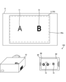
- FIG. 9 is a diagram showing a first example of changing the display mode of the marker image 71.
- the control device 4 performs a process of hiding the marker image 71 of the image 70, as shown in FIG. This process is an example of a process that reduces the visibility of the marker image 71.
- the marker image 71 is hidden, and the marker image 71 whose necessity has become low because the content image 73 has been played enough is hidden and the image 70
- the visibility of other parts of the content image 73 can be increased, and the number of times the content image 73 can be played back can be limited to create a premium feel.
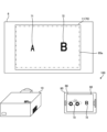
- FIG. 10 is a diagram showing a second example of changing the display mode of the marker image 71.
- the control device 4 performs a process of thinning the marker image 71 of the image 70, as shown in FIG.
- the process of thinning the marker image 71 is, for example, a process of bringing the brightness and color of the marker image 71 closer to the brightness and color of the peripheral part (background) of the marker image 71 in the image 70.
- the process of thinning the marker image 71 may be a process of increasing the transmittance of the image 70.
- the process of thinning these marker images 71 is an example of a process of reducing the visibility of the marker images 71.
- the marker image 71 when the content image 73 has been played more than a predetermined number of times, by making the marker image 71 thinner, the marker image 71 that has become less necessary as the content image 73 has been played back becomes less noticeable, and other images 70 By increasing the visibility of the portion or making it difficult to detect the marker image 71 on the information terminal 80, it is possible to limit the number of times the content image 73 can be played back and create a premium feel.
- FIG. 11 is a diagram showing a third example of changing the display mode of the marker image 71.
- the control device 4 performs a process of reducing the size of the marker image 71 of the image 70, as shown in FIG. This process is an example of a process that reduces the visibility of the marker image 71.
- the marker image 71 when the content image 73 has been played more than a predetermined number of times, by making the marker image 71 smaller, the marker image 71 that has become less necessary as the content image 73 has been played back becomes less noticeable, and other images 70 By increasing the visibility of the portion or making it difficult to detect the marker image 71 on the information terminal 80, it is possible to limit the number of times the content image 73 is played back and create a premium feel.
- the control device 4 performs processing to lower the visibility of the marker image 71 of the image 70 in step S15 of FIG. Further, the control device 4 may perform a combination of the processes shown in FIGS. 9 to 11 in step S15 in FIG. 8. For example, the control device 4 may perform processing to make the marker image 71 of the image 70 thinner and to make the marker image 71 of the image 70 smaller in step S15 in FIG. 8 .
- FIG. 12 is a diagram showing a fourth example of changing the display mode of the marker image 71.
- the control device 4 performs a process of blinking the marker image 71 of the image 70 as shown in FIG.
- the control device 4 performs a process of superimposing an image (for example, a beam of light) in which the marker image 71 appears to be emitting light on the image 70.
- an image for example, a beam of light
- the marker image 71 is made to blink or the like, thereby making the observer aware that the content based on the marker image 71 (content image 73) is being reproduced a lot;
- An observer who has an information terminal that has not yet reproduced the content image 73 can be effectively urged to take an image of the marker image 71 and be guided to reproduce the content image 73.
- FIG. 13 is a diagram showing a fifth example of changing the display mode of the marker image 71.
- the control device 4 performs a process of changing the color of the marker image 71 of the image 70 to a more conspicuous color, or changing the font of the marker image 71 to a more conspicuous font, as shown in FIG. I do.
- Each of these processes is an example of a process that increases the visibility of the marker image 71.
- the viewer can be made aware that the content based on the marker image 71 (content image 73) is being played a lot; An observer who has an information terminal that has not yet reproduced the content image 73 can be effectively urged to take an image of the marker image 71 and be guided to reproduce the content image 73.
- FIG. 14 is a diagram showing a sixth example of changing the display mode of the marker image 71.
- the control device 4 performs a process of enlarging the marker image 71 of the image 70 as shown in FIG. This process is an example of a process that increases the visibility of the marker image 71.
- the viewer can recognize that the content based on the marker image 71 (content image 73) has been played a lot, and An observer who has an information terminal that is not reproducing the content image 73 can be effectively urged to take an image of the marker image 71, and can be guided to reproducing the content image 73.
- the control device 4 may perform processing to increase the visibility of the marker image 71 of the image 70 in step S15 of FIG. Further, the control device 4 may perform a combination of the processes shown in FIGS. 12 to 14 in step S15 in FIG. 8. For example, in step S15 of FIG. 8, the control device 4 may perform processing to blink the marker image 71 of the image 70, change the color of the marker image 71 of the image 70, and enlarge the marker image 71 of the image 70. good.
- control device 4 performs processing to lower the visibility of the marker image 71 of the image 70 shown in FIGS. 9 to 11, and processing to increase the visibility of the marker image 71 of the image 70 shown in FIGS. 12 to 14. You may also perform this in combination.
- the visibility of the marker image 71 associated with the content image 73 can be changed depending on the reproduction status of the content image 73.
- FIG. 15 is a diagram showing an example of a display of an image representing information regarding the number of playbacks of the content image 73.
- the control device 4 may display information regarding the number of playbacks of the content image 73 in a superimposed manner on the image 70.
- the control device 4 includes, near the marker image 71 in the image 70, a reproduction number image 151 indicating the number of reproductions of the content image 73 associated with the marker image 71.
- the number of reproductions of the content image 73 is 256
- the reproduction number image 151 is an image indicating "256".
- the control device 4 may display the reproduction number image 151 in the examples of FIGS. 9 to 13.
- FIG. 16 is a diagram showing an example of a correspondence table for changing the display mode.
- FIG. 8 and the like a case has been described in which the display mode of the marker image 71 is changed once when the number of reproductions (information regarding the number of reproductions) satisfies the change condition, but the control device 4 , the display mode of the marker image 71 may be changed multiple times, for example in stages.
- the control device 4 can acquire the correspondence table 160 shown in FIG. 16.
- effects to be given to the marker image 71 are associated with each range of the number of reproductions. For example, in a range where the number of reproductions is from 0 to 100, there is no effect on the marker image 71. In a range where the number of reproductions is from 101 to 200, the effect given to the marker image 71 is A1. In the range where the number of reproductions is from 201 to 300, the effect given to the marker image 71 is A2. In the range of the number of reproductions from 301 to 400, the effect given to the marker image 71 is A3.
- the control device 4 changes the display mode of the marker image 71 in the image 70 based on the number of times the content image 73 has been played and the correspondence table 160. For example, if effects A1 to A3 are effects that make the size of the marker image 71 0.8 times, 0.6 times, and 0.4 times the original size, respectively, as the number of times the content image 73 is played increases, The size of the marker image 71 can be reduced in stages.
- control device 4 changes the display mode of the marker image 71 in the image 70 based on the number of times the content image 73 is played and a formula that can calculate the parameter of the effect given to the marker image 71 from the number of times the content image 73 is played. Good too.
- FIG. 17 is a diagram illustrating an example of a plurality of first images that can be played back by different information terminals.
- the marker image 72 may be associated with a content image 74 different from the content image 73, and the marker image 71 and the marker image 72 may use different information terminals that can reproduce the content.
- the content image 74 is a photographic image or an illustration image of a bird.
- the marker image 72 is an example of a first image associated with content.
- information terminals 80A and 80B shown in FIG. 17 are each similar to information terminal 80.
- the information terminal 80A plays back the content image 73 when the marker image 71 is detected from the captured image, it does not play back the content image 74 even when the marker image 72 is detected from the captured image.
- the information terminal 80A displays a superimposed image 90A in which the content image 73 is superimposed on the captured image.
- the information terminal 80B plays back the content image 74 when it detects the marker image 72 from the captured image, but does not play back the content image 73 even when it detects the marker image 71 from the captured image.
- the information terminal 80B displays a superimposed image 90B in which the content image 74 is superimposed on the captured image.
- the control device 4 acquires reproduction information for each of the marker images 71 and 72, that is, for each of the content image 73 and the content image 74. For example, the control device 4 obtains the number of times the content image 73 is played and the number of times the content image 74 is played.
- the control device 4 changes the display mode of the marker image 71 in the image 70 when the number of times the content image 73 is played satisfies the change condition, and changes the display mode of the marker image 71 in the image 70 when the number of times the content image 74 is played satisfies the change condition.
- the display mode of the marker image 72 in is changed. Thereby, the visibility of the marker image 71 can be changed according to the reproduction status of the content image 73, and the visibility of the marker image 72 can be changed according to the reproduction status of the content image 74.
- the changing conditions for changing the display mode of the marker image 71 and the changing conditions for changing the display mode of the marker image 72 may be different. Further, the method of changing the display mode of the marker image 71 and the method of changing the display mode of the marker image 72 may be different.
- FIG. 18 is a diagram illustrating an example of a display of attributes of an information terminal that can reproduce information.
- the control device 4 may include, in the image 70, an image indicating the attributes of the information terminal that can reproduce the associated content.
- each information terminal including the information terminals 80A and 80B may be provided with an electronic platinum ticket (A ticket) or a standard ticket (B ticket) depending on the contract or the like.
- an information terminal to which a platinum ticket is assigned detects a marker image 71, it plays back the content image 73, and an information terminal to which a standard ticket is assigned plays back a content image 74 when it detects a marker image 72.
- the information terminal 80A is given a platinum ticket
- the information terminal 80B is given a standard ticket.
- the control device 4 includes an attribute image 181 near the marker image 71 in the image 70, which indicates that the information terminal to which the platinum ticket has been given can reproduce the content.
- the attribute image 181 is a character image of "Platinum”.
- the control device 4 includes an attribute image 182 near the marker image 72 in the image 70, which indicates that the information terminal to which the standard ticket is attached can reproduce the content.
- the attribute image 182 is a character image of "Standard".
- the user can easily recognize the character image among the marker images 71 and 72 that allows the content to be played back on the information terminal that the user owns.
- the information regarding the number of reproductions of the content image 73 is not limited to the number of reproductions of the content image 73, but may be, for example, the cumulative number of reproductions of the content image 73.
- the cumulative number of reproductions of the content image 73 is the number of information terminals that have reproduced the content image 73.
- the control device 4 calculates the number of information terminals that are sources of the reproduction information received after step S11.
- the change condition in step S14 is, for example, that the cumulative number of reproductions of the content image 73 exceeds a predetermined number.
- the information regarding the number of reproductions of the content image 73 may be, for example, the number of devices that simultaneously reproduce the content image 73.
- the number of simultaneous reproductions of the content image 73 is the number of information terminals that are simultaneously reproducing the content image 73.
- the control device 4 determines whether or not the information terminal that is the source of the playback information is currently playing back the content image 73, thereby providing information regarding the number of playbacks of the content image 73.
- the number of devices that simultaneously reproduce the content image 73 is calculated.
- the control device 4 determines whether or not the information terminal that is the source of the reproduction information is currently reproducing the content image 73, and starts the reproduction of the content image 73 for each information terminal that is the source of the reproduction information. This is done by specifying the time and end time.
- the playback start time of the content image 73 may be specified based on the time when the playback information is received, or may be specified from the playback information by including the playback start time of the content image 73 in the playback information.
- the end time of the reproduction of the content image 73 may be specified from the start time of the reproduction of the content image 73 if the reproduction time length of the content image 73 is constant, or the end time of the reproduction of the content image 73 may be specified in the reproduction information. By including it, it may be specified from the playback information.
- the change condition in step S14 is, for example, that the number of devices that simultaneously reproduce the content image 73 exceeds a predetermined number.
- the control device 4 suppresses hunting in the display mode of the marker image 71.
- the display mode of the marker image 71 may be changed to gradually follow the change in information regarding the number of reproductions of the content image 73.
- the information regarding the number of playbacks of the content image 73 may be information calculated from a plurality of information among the number of playbacks of the content image 73, the cumulative number of playbacks of the content image 73, and the number of simultaneous playbacks of the content image 73. .
- the information terminal 80 plays back the content image 73 by reading the marker image 71, but the method for playing back the content image 73 is not limited to this.
- the image 70 includes a guide image (first image) that prompts reproduction of the content image 73 instead of or together with the marker image 71, and the user of the information terminal 80
- the content image 73 may be played back by operating the information terminal 80 according to the following.
- the first image with which content is associated is not limited to a character image, but may also be a graphic image showing a specific shape, or a two-dimensional image. It may also be a pattern image of a code or the like.
- FIG. 19 is a schematic diagram showing another external configuration of the projection device 10.
- FIG. 20 is a schematic cross-sectional view of the optical unit 106 of the projection apparatus 10 shown in FIG. 19.
- the same parts as those shown in FIGS. 4 and 5 are designated by the same reference numerals, and the description thereof will be omitted.
- the optical unit 106 includes a first member 102 supported by the main body 101 and a second member 103 supported by the first member 102.
- the first member 102 and the second member 103 may be an integrated member.
- the optical unit 106 includes, in addition to the first member 102, a second member 103 having a hollow portion 3A connected to the hollow portion 2A of the first member 102, and a first member disposed in the hollow portion 2A.
- the opening 2a and the opening 2b of the first member 102 are formed in planes perpendicular to each other.
- the projection optical system 23 shown in FIGS. 19 and 20 includes a reflection member 122, a second optical system 31, a reflection member 32, and It is constituted by a third optical system 33.
- the optical axis K is bent twice and turned back.
- the first optical system 121, the reflecting member 122, the second optical system 31, the reflecting member 32, the third optical system 33, and the lens 34 are arranged along the optical axis K in this order from the light modulating section 22 side.
- the first optical system 121 guides the light incident on the first member 102 from the main body 101 and traveling in the direction X1 to the reflecting member 122.
- the reflecting member 122 reflects the light incident from the first optical system 121 in the direction Y1.
- the reflecting member 122 is composed of, for example, a mirror.
- the first member 102 has an opening 2b formed on the optical path of the light reflected by the reflecting member 122, and the reflected light passes through the opening 2b and advances to the hollow portion 3A of the second member 103.
- the second member 103 is a member having a substantially L-shaped cross-sectional outline, and has an opening 3a formed at a position facing the opening 2b of the first member 102.
- the light from the main body portion 101 that has passed through the opening 2b of the first member 102 is incident on the hollow portion 3A of the second member 103 through this opening 3a.
- the cross-sectional shapes of the first member 102 and the second member 103 are arbitrary, and are not limited to those described above.
- the second optical system 31 includes at least one lens and guides the light incident from the first member 102 to the reflecting member 32.
- the reflecting member 32 reflects the light incident from the second optical system 31 in the direction X2 and guides it to the third optical system 33.
- the reflecting member 32 is formed of, for example, a mirror.
- the third optical system 33 includes at least one lens, and guides the light reflected by the reflecting member 32 to the lens 34.
- the lens 34 is arranged at the end of the second member 103 in the direction X2 so as to close the opening 3c formed at this end.
- the lens 34 projects the light incident from the third optical system 33 onto the projection target 6.
- FIG. 20 shows a state in which the first member 102 is moved to the maximum extent in the direction Y1 by the first shift mechanism 105. From the state shown in FIG. 20, by moving the first member 102 in the direction Y2 by the first shift mechanism 105, the relative position between the center of the image formed by the light modulating section 22 and the optical axis K changes. , the image G1 projected onto the projection object 6 can be shifted in the direction Y1.
- the projection direction changing mechanism 104 is a rotation mechanism that rotatably connects the second member 103 to the first member 102.
- the projection direction changing mechanism 104 allows the second member 103 to rotate around a rotation axis (specifically, the optical axis K) extending in the Y direction.
- a rotation axis specifically, the optical axis K
- the projection direction changing mechanism 104 is not limited to the arrangement position shown in FIG. 20 as long as it can rotate the optical system. Further, the number of rotation mechanisms is not limited to one, and a plurality of rotation mechanisms may be provided.
- control device of the present invention is applied to the control device 4 of the projection device 10
- the configuration is not limited to this.
- FIG. 21 is a diagram showing a modification of the system 100.
- a system 100 shown in FIG. 21 includes an information terminal 110 in addition to the configuration of the system 100 shown in FIG.
- the control device of the present invention may be applied to the information terminal 110.
- the information terminal 110 is an information terminal that can communicate with the projection device 10 directly or indirectly. Communication between the information terminal 110 and the projection device 10 may be wired communication or wireless communication.
- the information terminal 110 executes various controls by the control device 4 described above by communicating with the projection device 10 .
- the information terminal 110 is a notebook personal computer, but the information terminal 110 can be any of various information terminals such as a desktop personal computer, a smartphone, or a tablet terminal.
- the reproduction information of the content image 73 is received from an information terminal such as the information terminal 80, and based on the received reproduction information, the marker image 71 in the image 70 is Performs control to change the display mode of.
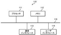
- FIG. 22 is a diagram showing an example of the hardware configuration of the information terminal 110.
- the information terminal 110 shown in FIG. 1 includes a processor 111, a memory 112, a communication interface 113, and a user interface 114, as shown in FIG.
- Processor 111, memory 112, communication interface 113, and user interface 114 are connected by bus 119, for example.
- the processor 111, memory 112, communication interface 113, and user interface 114 have the same configuration as the processor 81, memory 82, communication interface 83, and user interface 84 shown in FIG. 6, respectively.
- images such as content images 73 and 74 have been described as examples of content associated with the image 70, the content associated with the image 70 is not limited to images.
- the content associated with the image 70 may be content other than images that can be played back by the information terminal 80, such as audio and vibration.
Landscapes
- Engineering & Computer Science (AREA)
- Multimedia (AREA)
- Signal Processing (AREA)
- Theoretical Computer Science (AREA)
- General Engineering & Computer Science (AREA)
- Physics & Mathematics (AREA)
- General Physics & Mathematics (AREA)
- Human Computer Interaction (AREA)
- Computer Graphics (AREA)
- Computer Hardware Design (AREA)
- Software Systems (AREA)
- Controls And Circuits For Display Device (AREA)
Priority Applications (2)
| Application Number | Priority Date | Filing Date | Title |
|---|---|---|---|
| JP2024521628A JPWO2023223760A1 (https=) | 2022-05-18 | 2023-04-19 | |
| US18/949,731 US12556665B2 (en) | 2022-05-18 | 2024-11-15 | Control device, control method, control program, and system |
Applications Claiming Priority (2)
| Application Number | Priority Date | Filing Date | Title |
|---|---|---|---|
| JP2022081604 | 2022-05-18 | ||
| JP2022-081604 | 2022-05-18 |
Related Child Applications (1)
| Application Number | Title | Priority Date | Filing Date |
|---|---|---|---|
| US18/949,731 Continuation US12556665B2 (en) | 2022-05-18 | 2024-11-15 | Control device, control method, control program, and system |
Publications (1)
| Publication Number | Publication Date |
|---|---|
| WO2023223760A1 true WO2023223760A1 (ja) | 2023-11-23 |
Family
ID=88834969
Family Applications (1)
| Application Number | Title | Priority Date | Filing Date |
|---|---|---|---|
| PCT/JP2023/015649 Ceased WO2023223760A1 (ja) | 2022-05-18 | 2023-04-19 | 制御装置、制御方法、制御プログラム、及びシステム |
Country Status (3)
| Country | Link |
|---|---|
| US (1) | US12556665B2 (https=) |
| JP (1) | JPWO2023223760A1 (https=) |
| WO (1) | WO2023223760A1 (https=) |
Citations (7)
| Publication number | Priority date | Publication date | Assignee | Title |
|---|---|---|---|---|
| JP5299054B2 (ja) * | 2009-04-21 | 2013-09-25 | ソニー株式会社 | 電子機器、表示制御方法およびプログラム |
| US20150309578A1 (en) * | 2014-04-23 | 2015-10-29 | Sony Corporation | Control of a real world object user interface |
| JP6292478B2 (ja) * | 2014-06-17 | 2018-03-14 | コニカミノルタ株式会社 | 透過型hmdを有する情報表示システム及び表示制御プログラム |
| WO2018216402A1 (ja) * | 2017-05-23 | 2018-11-29 | ソニー株式会社 | 情報処理装置、情報処理方法、及びプログラム |
| JP6559190B2 (ja) * | 2017-07-31 | 2019-08-14 | ヤフー株式会社 | 情報表示プログラム、情報表示装置、情報表示方法および配信装置 |
| JP6695833B2 (ja) * | 2017-07-31 | 2020-05-20 | ヤフー株式会社 | 情報表示プログラム、情報表示装置、情報表示方法および配信装置 |
| JP6706977B2 (ja) * | 2016-06-20 | 2020-06-10 | ヤフー株式会社 | 情報表示プログラム、情報表示装置、情報表示方法および配信装置 |
Family Cites Families (9)
| Publication number | Priority date | Publication date | Assignee | Title |
|---|---|---|---|---|
| JP5632073B2 (ja) | 2010-08-06 | 2014-11-26 | ビズモードライン カンパニー リミテッド | 拡張現実のための装置および方法 |
| JP6318519B2 (ja) | 2013-09-26 | 2018-05-09 | カシオ計算機株式会社 | 画像処理装置、プログラム及び制御方法 |
| JP2018054880A (ja) * | 2016-09-29 | 2018-04-05 | セイコーエプソン株式会社 | 表示装置、情報処理装置および情報処理方法 |
| JP6924662B2 (ja) | 2017-09-26 | 2021-08-25 | 株式会社Nttドコモ | 情報処理装置 |
| JP2021060829A (ja) | 2019-10-08 | 2021-04-15 | 一般社団法人未来ものづくり振興会 | Ar画像を生成させる携帯端末装置及びそれに利用される印判 |
| JP2022148856A (ja) * | 2021-03-24 | 2022-10-06 | 本田技研工業株式会社 | 車両用表示装置、表示制御方法、及びプログラム |
| JP7815708B2 (ja) * | 2021-11-25 | 2026-02-18 | セイコーエプソン株式会社 | 表示システム、及び表示システムの制御方法 |
| JP7533515B2 (ja) * | 2022-03-29 | 2024-08-14 | セイコーエプソン株式会社 | 投写画像の補正方法及び投写システム |
| JP2024045930A (ja) * | 2022-09-22 | 2024-04-03 | セイコーエプソン株式会社 | 表示方法および表示装置 |
-
2023
- 2023-04-19 WO PCT/JP2023/015649 patent/WO2023223760A1/ja not_active Ceased
- 2023-04-19 JP JP2024521628A patent/JPWO2023223760A1/ja active Pending
-
2024
- 2024-11-15 US US18/949,731 patent/US12556665B2/en active Active
Patent Citations (7)
| Publication number | Priority date | Publication date | Assignee | Title |
|---|---|---|---|---|
| JP5299054B2 (ja) * | 2009-04-21 | 2013-09-25 | ソニー株式会社 | 電子機器、表示制御方法およびプログラム |
| US20150309578A1 (en) * | 2014-04-23 | 2015-10-29 | Sony Corporation | Control of a real world object user interface |
| JP6292478B2 (ja) * | 2014-06-17 | 2018-03-14 | コニカミノルタ株式会社 | 透過型hmdを有する情報表示システム及び表示制御プログラム |
| JP6706977B2 (ja) * | 2016-06-20 | 2020-06-10 | ヤフー株式会社 | 情報表示プログラム、情報表示装置、情報表示方法および配信装置 |
| WO2018216402A1 (ja) * | 2017-05-23 | 2018-11-29 | ソニー株式会社 | 情報処理装置、情報処理方法、及びプログラム |
| JP6559190B2 (ja) * | 2017-07-31 | 2019-08-14 | ヤフー株式会社 | 情報表示プログラム、情報表示装置、情報表示方法および配信装置 |
| JP6695833B2 (ja) * | 2017-07-31 | 2020-05-20 | ヤフー株式会社 | 情報表示プログラム、情報表示装置、情報表示方法および配信装置 |
Also Published As
| Publication number | Publication date |
|---|---|
| US12556665B2 (en) | 2026-02-17 |
| JPWO2023223760A1 (https=) | 2023-11-23 |
| US20250080702A1 (en) | 2025-03-06 |
Similar Documents
| Publication | Publication Date | Title |
|---|---|---|
| US9039195B2 (en) | Projector, image projecting system, and image projecting method | |
| CN102722289B (zh) | 图像供给装置、图像显示系统和图像供给装置的控制方法 | |
| CN114450621B (zh) | 头戴式显示器 | |
| CN107526237B (zh) | 投影装置、投影系统、投影方法 | |
| US20090243968A1 (en) | Head mount display and head mount display system | |
| CN101406047A (zh) | 基于投影仪的周边照明系统 | |
| CN117597663A (zh) | 用于扩展现实界面的远程界标渲染 | |
| WO2019123509A1 (ja) | 端末装置、システム、プログラム及び方法 | |
| CN115112042A (zh) | 检测装置、检测方法以及空间投影装置 | |
| JP4590858B2 (ja) | 書き込み可能プロジェクタおよび光ポインタ | |
| CN114374827B (zh) | 显示方法和显示装置 | |
| WO2023223760A1 (ja) | 制御装置、制御方法、制御プログラム、及びシステム | |
| JP2012234149A (ja) | 映像投影装置 | |
| JP2025114850A (ja) | エンターテインメントシステム及びプログラム | |
| TW201826781A (zh) | 投影單元及應用其的投影裝置 | |
| JP7649715B2 (ja) | 制御装置、制御方法、投影システム、及び制御プログラム | |
| US12267634B2 (en) | Projection apparatus, projection method, control device, and control program | |
| US20240312164A1 (en) | Control device, control method, and control program | |
| JP6295758B2 (ja) | 表示装置、および表示装置の制御方法 | |
| JP2011107563A (ja) | 表示システム、画像出力装置、制御方法及び記録媒体 | |
| JP4807003B2 (ja) | 投影装置及び投影方法 | |
| JP7427804B2 (ja) | 制御装置、制御方法、制御プログラム、及び投影システム | |
| US20180275774A1 (en) | Display control device, display control system, display control method, and storage medium having stored thereon display control program | |
| JP2021068145A (ja) | 頭部装着型表示装置の動作方法および頭部装着型表示装置 | |
| US20250286983A1 (en) | Projection apparatus, projection system, control method, and control program |
Legal Events
| Date | Code | Title | Description |
|---|---|---|---|
| 121 | Ep: the epo has been informed by wipo that ep was designated in this application |
Ref document number: 23807372 Country of ref document: EP Kind code of ref document: A1 |
|
| WWE | Wipo information: entry into national phase |
Ref document number: 2024521628 Country of ref document: JP |
|
| NENP | Non-entry into the national phase |
Ref country code: DE |
|
| 122 | Ep: pct application non-entry in european phase |
Ref document number: 23807372 Country of ref document: EP Kind code of ref document: A1 |