WO2023223760A1 - Control device, control method, control program, and system - Google Patents
Control device, control method, control program, and system Download PDFInfo
- Publication number
- WO2023223760A1 WO2023223760A1 PCT/JP2023/015649 JP2023015649W WO2023223760A1 WO 2023223760 A1 WO2023223760 A1 WO 2023223760A1 JP 2023015649 W JP2023015649 W JP 2023015649W WO 2023223760 A1 WO2023223760 A1 WO 2023223760A1
- Authority
- WO
- WIPO (PCT)
- Prior art keywords
- image
- content
- control device
- information
- projection
- Prior art date
Links
- 238000000034 method Methods 0.000 title claims abstract description 47
- 230000033458 reproduction Effects 0.000 claims description 72
- 230000008569 process Effects 0.000 claims description 34
- 239000003550 marker Substances 0.000 abstract description 135
- 230000008859 change Effects 0.000 abstract description 17
- 230000003287 optical effect Effects 0.000 description 85
- 238000010586 diagram Methods 0.000 description 40
- 230000007246 mechanism Effects 0.000 description 37
- 238000004891 communication Methods 0.000 description 33
- 230000015654 memory Effects 0.000 description 24
- 238000003384 imaging method Methods 0.000 description 18
- BASFCYQUMIYNBI-UHFFFAOYSA-N platinum Chemical compound [Pt] BASFCYQUMIYNBI-UHFFFAOYSA-N 0.000 description 10
- 230000000694 effects Effects 0.000 description 8
- 239000004973 liquid crystal related substance Substances 0.000 description 7
- 230000003190 augmentative effect Effects 0.000 description 5
- 229910052697 platinum Inorganic materials 0.000 description 5
- 230000001186 cumulative effect Effects 0.000 description 4
- 230000004048 modification Effects 0.000 description 3
- 238000012986 modification Methods 0.000 description 3
- 230000002093 peripheral effect Effects 0.000 description 2
- 239000004065 semiconductor Substances 0.000 description 2
- 238000000926 separation method Methods 0.000 description 2
- 230000009471 action Effects 0.000 description 1
- 230000004397 blinking Effects 0.000 description 1
- 239000003086 colorant Substances 0.000 description 1
- 230000000295 complement effect Effects 0.000 description 1
- 239000000470 constituent Substances 0.000 description 1
- 230000007423 decrease Effects 0.000 description 1
- 238000005516 engineering process Methods 0.000 description 1
- 230000010365 information processing Effects 0.000 description 1
- 238000004519 manufacturing process Methods 0.000 description 1
- 230000004044 response Effects 0.000 description 1
- 229910052710 silicon Inorganic materials 0.000 description 1
- 239000010703 silicon Substances 0.000 description 1
- 239000007787 solid Substances 0.000 description 1
- 238000002834 transmittance Methods 0.000 description 1
Images


Classifications
-
- G—PHYSICS
- G06—COMPUTING; CALCULATING OR COUNTING
- G06F—ELECTRIC DIGITAL DATA PROCESSING
- G06F3/00—Input arrangements for transferring data to be processed into a form capable of being handled by the computer; Output arrangements for transferring data from processing unit to output unit, e.g. interface arrangements
- G06F3/01—Input arrangements or combined input and output arrangements for interaction between user and computer
- G06F3/048—Interaction techniques based on graphical user interfaces [GUI]
- G06F3/0481—Interaction techniques based on graphical user interfaces [GUI] based on specific properties of the displayed interaction object or a metaphor-based environment, e.g. interaction with desktop elements like windows or icons, or assisted by a cursor's changing behaviour or appearance
-
- G—PHYSICS
- G06—COMPUTING; CALCULATING OR COUNTING
- G06F—ELECTRIC DIGITAL DATA PROCESSING
- G06F3/00—Input arrangements for transferring data to be processed into a form capable of being handled by the computer; Output arrangements for transferring data from processing unit to output unit, e.g. interface arrangements
- G06F3/14—Digital output to display device ; Cooperation and interconnection of the display device with other functional units
-
- G—PHYSICS
- G06—COMPUTING; CALCULATING OR COUNTING
- G06T—IMAGE DATA PROCESSING OR GENERATION, IN GENERAL
- G06T19/00—Manipulating 3D models or images for computer graphics
Definitions
- the present invention relates to a control device, a control method, a control program, and a system.
- Patent Document 1 discloses a method for augmented reality in which a real world image including a marker is generated, the marker is detected from the real world image, an object image corresponding to the detected marker is combined with the real world image, It is stated that the combined image will be displayed.
- Patent Document 2 discloses that in an image taken of a real space including a display area where no products are displayed, a product image is displayed superimposed on the display area in the real space, and the product image superimposed in the real space is In response, when a user performs a first action, an information processing apparatus is described that performs processing for ordering a product corresponding to the product image.
- Patent Document 3 discloses that when it is recognized that a specific object has entered the frame within the screen of the display unit, and the number of frame-in recognitions matches a preset number of recognitions, a predetermined display is displayed according to the number of recognitions. An image processing device that performs this is described.
- Patent Document 4 discloses a method for capturing an image of a seal including a name and a marker placed around the name, extracting a seal image from the captured image, extracting a marker included in the seal from the seal image, and extracting the image.
- a mobile terminal device is described that selects and generates a generated image associated with a marker from a generated image database.
- One embodiment of the technology of the present disclosure provides a control device, a control method, a control program, and a system that can change the visibility of an image associated with content depending on the playback status of the content. .
- a control device comprising a processor, The above processor is projecting a second image including the first image associated with the content from a projection device; Obtain playback information regarding playback of the above content by the information terminal, changing the display mode of the first image in the second image based on the reproduction information; Control device.
- Changing the display mode of the first image is a process of changing the visibility of the first image, Control device.
- the control device according to any one of (1) to (4),
- the playback information is information regarding the number of playbacks of the content, Control device.
- the control device includes information indicating the number of times the content has been played by one or more information terminals; Control device.
- the control device includes information indicating the number of information terminals that have played the content; Control device.
- the control device according to any one of (5) to (7),
- the information regarding the number of playbacks of the content includes information indicating the number of information terminals that are simultaneously playing the content; Control device.
- the control device according to any one of (5) to (8),
- the second image includes an image representing information regarding the number of plays of the content, Control device.
- the control device according to any one of (1) to (9),
- the first image includes a plurality of first images that can be played back by different information terminals,
- the processor obtains the reproduction information regarding the plurality of first images. Control device.
- the controller's processor projecting a second image including the first image associated with the content from a projection device; Obtain playback information regarding playback of the above content by the information terminal, changing the display mode of the first image in the second image based on the reproduction information; Control method.
- control device it is possible to provide a control device, a control method, a control program, and a system that can change the visibility of an image associated with content depending on the playback status of the content.
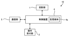
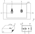
- FIG. 1 is a diagram illustrating an example of a system 100 according to an embodiment.
- 1 is a diagram showing an example of the configuration of a projection device 10.
- FIG. 2 is a schematic diagram showing an example of the internal configuration of the projection section 1.
- FIG. 1 is a diagram showing an example of an external configuration of a projection device 10.
- FIG. 5 is a schematic partial cross-sectional view of the optical unit 106 of the projection device 10 shown in FIG. 4.
- FIG. 3 is a diagram showing an example of the hardware configuration of an information terminal 80.
- FIG. FIG. 3 is a diagram illustrating an example of image projection and playback of augmented reality content.
- 4 is a diagram showing an example of processing by the control device 4.
- FIG. 7 is a diagram showing a first example of changing the display mode of a marker image 71.
- FIG. 7 is a diagram illustrating a second example of changing the display mode of a marker image 71.
- FIG. 7 is a diagram illustrating a third example of changing the display mode of a marker image 71.
- FIG. 7 is a diagram showing a fourth example of changing the display mode of a marker image 71;
- FIG. 7 is a diagram showing a fifth example of changing the display mode of a marker image 71;
- FIG. 7 is a diagram showing a sixth example of changing the display mode of a marker image 71;
- 7 is a diagram illustrating an example of a display of an image representing information regarding the number of reproductions of a content image 73.
- FIG. FIG. 7 is a diagram illustrating an example of a correspondence table for changing the display mode.
- FIG. 7 is a diagram illustrating an example of a correspondence table for changing the display mode.
- FIG. 6 is a diagram illustrating an example of a plurality of first images on different information terminals that can play content.
- FIG. 3 is a diagram illustrating an example of a display of attributes of an information terminal that can be reproduced.
- 3 is a schematic diagram showing another external configuration of the projection device 10.
- FIG. 20 is a schematic cross-sectional view of the optical unit 106 of the projection device 10 shown in FIG. 19.
- FIG. 3 is a diagram showing a modification of the system 100.
- FIG. 1 is a diagram showing an example of a hardware configuration of an information terminal 110.
- FIG. 1 is a diagram illustrating an example of a system 100 according to an embodiment.
- the system 100 includes a projection device 10 and an information terminal 80.
- the control device in the present invention is applied to the projection device 10, for example.
- the projection device 10 is a projection device capable of projecting onto the projection target 6.
- the projection object 6 is an object such as a screen or a wall that has a projection surface on which a projected image is displayed by the projection device 10.
- the projection surface of the projection object 6 is a rectangular plane. It is assumed that the top, bottom, right and left of the projection target 6 in FIG. 1 are the top, bottom, left and right of the actual projection target 6.
- a projection range 11 illustrated by a dashed line is an area of the projection target 6 that is irradiated with projection light by the projection device 10.
- the projection range 11 is part or all of the projectable range that can be projected by the projection device 10 .
- the projection range 11 is rectangular.
- the information terminal 80 is an information terminal, such as a smartphone or a tablet terminal, that has an imaging section (for example, the imaging module 85 in FIG. 6) and a display section 86.
- an imaging section for example, the imaging module 85 in FIG. 6
- the information terminal 80 superimposes predetermined augmented reality (AR) content on the captured image.
- An application for displaying a superimposed image on the display unit 86 is stored (installed).
- AR augmented reality
- FIG. 2 is a diagram showing an example of the configuration of the projection device 10.
- the projection device 10 includes, for example, a projection section 1, a control device 4, and an operation reception section 2.
- the projection device 10 may further include a communication section 5.
- the projection unit 1 is configured by, for example, a liquid crystal projector or a projector using LCOS (Liquid Crystal On Silicon). The following description will be made assuming that the projection unit 1 is a liquid crystal projector.
- LCOS Liquid Crystal On Silicon
- the control device 4 is an example of the control device of the present invention.
- the control device 4 controls projection by the projection device 10 .
- the control device 4 includes a control section composed of various processors, a communication interface (not shown) for communicating with each section, and a storage medium such as a hard disk, SSD (Solid State Drive), or ROM (Read Only Memory). 4a, and centrally controls the projection unit 1.
- Various processors in the control unit of the control device 4 include a CPU (Central Processing Unit), which is a general-purpose processor that executes programs and performs various processes, and an FPGA (Field Programmable Gate Array), whose circuit configurations are changed after manufacturing.
- CPU Central Processing Unit
- FPGA Field Programmable Gate Array
- a dedicated electric circuit which is a processor with a circuit configuration, etc. is included.
- the structure of these various processors is an electric circuit that combines circuit elements such as semiconductor elements.
- the control unit of the control device 4 may be configured with one of various processors, or a combination of two or more processors of the same type or different types (for example, a combination of multiple FPGAs or a combination of a CPU and an FPGA). It may be composed of.
- the operation reception unit 2 detects instructions from the user (user instructions) by accepting various operations from the user.
- the operation reception section 2 may be a button, a key, a joystick, etc. provided on the control device 4, or may be a reception section or the like that receives a signal from a remote controller that remotely controls the control device 4.
- the communication unit 5 is a communication interface that can communicate with other devices.
- the communication unit 5 may be a wired communication interface that performs wired communication, or may be a wireless communication interface that performs wireless communication.
- the projection unit 1, the control device 4, the operation reception unit 2, and the communication unit 5 are realized by, for example, one device (see, for example, FIGS. 4 and 5).
- the projection unit 1, the control device 4, the operation reception unit 2, and the communication unit 5 may be realized by a plurality of devices that can cooperate by communicating with each other.
- FIG. 3 is a schematic diagram showing an example of the internal configuration of the projection section 1.
- the projection section 1 of the projection apparatus 10 shown in FIG. 2 includes a light source 21, a light modulation section 22, a projection optical system 23, and a control circuit 24, as shown in FIG.
- the light source 21 includes a light emitting element such as a laser or an LED (Light Emitting Diode), and emits, for example, white light.
- the light modulation unit 22 modulates each color light emitted from the light source 21 and separated into three colors of red, blue, and green by a color separation mechanism (not shown) based on image information, and outputs each color image. It is composed of a liquid crystal panel (light modulation element) and a dichroic prism that mixes each color image emitted from the three liquid crystal panels and emits it in the same direction. Red, blue, and green filters may be mounted on each of these three liquid crystal panels, and the white light emitted from the light source 21 may be modulated by each liquid crystal panel to emit each color image.
- the projection optical system 23 receives light from the light source 21 and the light modulation section 22, and is configured by, for example, a relay optical system including at least one lens. The light passing through the projection optical system 23 is projected onto the projection target 6.
- a region of the projection target 6 that is irradiated with light that passes through the entire range of the light modulation section 22 becomes a projectable range that can be projected by the projection section 1.
- the area to which the light actually transmitted from the light modulation section 22 is irradiated becomes the projection range 11 of the projection section 1 .
- the size, position, and shape of a region of the light modulation section 22 through which light passes are changed in the projectable range.
- the control circuit 24 controls the light source 21, the light modulation section 22, and the projection optical system 23 based on the display data input from the control device 4, so that an image based on the display data is displayed on the projection target 6. to be projected.
- the display data input to the control circuit 24 is composed of three pieces: red display data, blue display data, and green display data.
- control circuit 24 expands or reduces the projection range of the projection unit 1 by changing the projection optical system 23 based on commands input from the control device 4. Further, the control device 4 may move the projection range of the projection unit 1 by changing the projection optical system 23 based on a user's operation accepted by the operation reception unit 2.
- the projection device 10 includes a shift mechanism that mechanically or optically moves the projection range of the projection unit 1 while maintaining the image circle of the projection optical system 23.
- the image circle of the projection optical system 23 is an area in which the projection light incident on the projection optical system 23 passes through the projection optical system 23 appropriately in terms of light falloff, color separation, peripheral curvature, and the like.
- the shift mechanism is realized by at least one of an optical system shift mechanism that shifts the optical system and an electronic shift mechanism that shifts the electronic system.
- the optical system shift mechanism is, for example, a mechanism that moves the projection optical system 23 in a direction perpendicular to the optical axis (see, for example, FIGS. 5 and 20), or a mechanism that moves the optical modulator 22 along the optical axis instead of moving the projection optical system 23. This is a mechanism that moves the object in a direction perpendicular to the direction. Further, the optical system shift mechanism may be a mechanism that combines the movement of the projection optical system 23 and the movement of the light modulation section 22.
- the electronic shift mechanism is a mechanism that performs a pseudo projection range shift by changing the range through which light is transmitted in the light modulation section 22.
- the projection device 10 may include a projection direction changing mechanism that moves the projection range together with the image circle of the projection optical system 23.
- the projection direction changing mechanism is a mechanism that changes the projection direction of the projection section 1 by changing the direction of the projection section 1 by mechanical rotation (see, for example, FIG. 20).
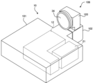
- FIG. 4 is a diagram showing an example of the external configuration of the projection device 10.
- FIG. 5 is a schematic partial cross-sectional view of the optical unit 106 of the projection apparatus 10 shown in FIG. 4.
- FIG. 5 shows a cross section taken along the optical path of light emitted from the main body 101 shown in FIG.
- the projection device 10 includes a main body 101 and an optical unit 106 provided to protrude from the main body 101.
- the operation reception section 2, the control device 4, the light source 21, the light modulation section 22, and the control circuit 24 in the projection section 1, and the communication section 5 are provided in the main body section 101.
- the projection optical system 23 in the projection section 1 is provided in the optical unit 106.
- the optical unit 106 includes a first member 102 supported by the main body 101.
- the optical unit 106 may be configured to be detachably attached to the main body portion 101 (in other words, configured to be replaceable).
- the main body portion 101 has a casing 15 in which an opening 15a for passing light is formed in a portion connected to the optical unit 106.
- a light source 21 As shown in FIG. 4, inside the casing 15 of the main body section 101, there is a light source 21 and a light modulation section 22 (which generates an image by spatially modulating the light emitted from the light source 21 based on input image data). (see FIG. 3).
- the light emitted from the light source 21 enters the light modulation section 22 of the light modulation unit 12, is spatially modulated by the light modulation section 22, and is emitted.
- Image G1 becomes visible to the observer.
- the optical unit 106 includes a first member 102 having a hollow portion 2A connected to the inside of the main body 101, a first optical system 121 disposed in the hollow portion 2A, a lens 34, and a first member 102.
- a shift mechanism 105 is provided.
- the first member 102 is a member having a rectangular cross-sectional outer shape, for example, and the opening 2a and the opening 2b are formed in planes parallel to each other.
- the first member 102 is supported by the main body 101 with the opening 2a facing the opening 15a of the main body 101.
- Light emitted from the light modulation section 22 of the light modulation unit 12 of the main body section 101 is incident on the hollow section 2A of the first member 102 through the opening 15a and the opening 2a.
- the direction of incidence of light entering the hollow portion 2A from the main body portion 101 is referred to as a direction X1, the direction opposite to the direction X1 is referred to as a direction X2, and the directions X1 and X2 are collectively referred to as a direction X.
- the direction from the front to the back of the page and the opposite direction are referred to as direction Z.
- the direction from the front to the back of the page is referred to as a direction Z1
- the direction from the back to the front of the page is referred to as a direction Z2.
- the direction perpendicular to the direction X and the direction Z is described as a direction Y, the direction going upward in FIG. .
- the projection device 10 is arranged so that the direction Y2 is the vertical direction.
- the projection optical system 23 shown in FIG. 3 is composed of the first optical system 121 and the lens 34 in the example shown in FIG. FIG. 5 shows the optical axis K of this projection optical system 23.
- the first optical system 121 and the lens 34 are arranged along the optical axis K in this order from the light modulation section 22 side.
- the first optical system 121 includes at least one lens, and guides the light incident on the first member 102 from the main body 101 and traveling in the direction X1 to the lens 34.
- the lens 34 is arranged at the end of the first member 102 in the direction X1 so as to close the opening 2b formed at this end.
- the lens 34 projects the light incident from the first optical system 121 onto the projection target 6.
- the first shift mechanism 105 is a mechanism for moving the optical axis K of the projection optical system (in other words, the optical unit 106) in a direction perpendicular to the optical axis K (direction Y in FIG. 5). Specifically, the first shift mechanism 105 is configured to be able to change the position of the first member 102 in the direction Y with respect to the main body portion 101.
- the first shift mechanism 105 may be one that moves the first member 102 manually or may be one that moves the first member 102 electrically.
- FIG. 5 shows a state in which the first member 102 is moved to the maximum extent in the direction Y1 by the first shift mechanism 105. From the state shown in FIG. 5, the first member 102 is moved in the direction Y2 by the first shift mechanism 105, thereby moving the center of the image formed by the light modulating section 22 (in other words, the center of the display surface) and the optical axis K.
- the image G1 projected onto the projection object 6 can be shifted (translated) in the direction Y2 by changing the relative position with respect to the projection object 6.
- the first shift mechanism 105 may be a mechanism that moves the light modulation section 22 in the Y direction instead of moving the optical unit 106 in the Y direction. Even in this case, the image G1 projected onto the projection object 6 can be moved in the direction Y.
- FIG. 6 is a diagram showing an example of the hardware configuration of the information terminal 80.
- the information terminal 80 shown in FIG. 1 includes a processor 81, a memory 82, a communication interface 83, a user interface 84, and an imaging module 85, as shown in FIG.
- the processor 81, memory 82, communication interface 83, user interface 84, and imaging module 85 are connected by, for example, a bus 89.
- the processor 81 is a circuit that performs signal processing, and is, for example, a CPU that controls the entire information terminal 80. Note that the processor 81 may be realized by other digital circuits such as an FPGA or a DSP (Digital Signal Processor). Further, the processor 81 may be realized by combining a plurality of digital circuits.
- the memory 82 includes, for example, a main memory and an auxiliary memory.
- the main memory is, for example, RAM (Random Access Memory).
- the main memory is used as a work area for the processor 81.
- the auxiliary memory is, for example, nonvolatile memory such as a magnetic disk, optical disk, or flash memory.
- Various programs for operating the information terminal 80 are stored in the auxiliary memory.
- the program stored in the auxiliary memory is loaded into the main memory and executed by the processor 81.
- auxiliary memory may include a portable memory that is removable from the information terminal 80.
- Portable memories include memory cards such as USB (Universal Serial Bus) flash drives and SD (Secure Digital) memory cards, external hard disk drives, and the like.
- the communication interface 83 is a communication interface that communicates with an external device of the information terminal 80. Communication interface 83 is controlled by processor 81 .
- the communication interface 83 may be a wired communication interface that performs wired communication, a wireless communication interface that performs wireless communication, or may include both a wired communication interface and a wireless communication interface.
- the user interface 84 includes, for example, an input device that receives operation input from the user, an output device that outputs information to the user, and the like.
- the input device can be realized by, for example, a pointing device (for example, a mouse), keys (for example, a keyboard), a remote control, or the like.
- the output device can be realized by, for example, a display or a speaker. Further, the input device and the output device may be realized by a touch panel or the like.
- User interface 84 is controlled by processor 81 .
- the display unit 86 of the information terminal 80 shown in FIG. 1 is realized by, for example, a touch panel included in the user interface 84.
- the imaging module 85 is an imaging unit that includes an imaging lens and an imaging element.
- the image sensor for example, a CMOS (complementary metal-oxide-semiconductor) image sensor can be used.
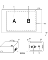
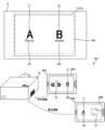
- FIG. 7 is a diagram illustrating an example of image projection and playback of augmented reality content.
- the image 70 is an image to be projected by the projection device 10.
- the image 70 is an image including a marker image 71 representing "A" and a marker image 72 representing "B".
- the marker image 71 is an example of a first image associated with content.
- the image 70 is an example of a second image including a first image associated with content.
- the control device 4 of the projection device 10 outputs image data representing the image 70 to the projection section 1 of the projection device 10. As a result, the image 70 based on the image data is projected onto the projection range 11.
- the imaging range 85a indicates the imaging range by the imaging module 85 of the information terminal 80. That is, by imaging by the imaging module 85 of the information terminal 80, a captured image representing the imaging range 85a of the projection target object 6 is obtained.
- the information terminal 80 When the marker image 71 is included in the captured image obtained by the imaging module 85, the information terminal 80 generates a superimposed image 90 in which the content image 73 is superimposed at the position of the marker image 71 in the captured image together with the captured image.
- An application is stored (installed) for displaying on the display unit 86.
- the content image 73 is an example of content associated with the marker image 71, and in the example of FIG. 7, it is a photographic image or an illustration image of a sports car. Further, in the example of FIG. 7, a range including marker images 71 and 72 of the image 70 is captured by the information terminal 80, and a superimposed image 90 in which the content image 73 is superimposed on the marker image 71 of the image 70 is It is displayed on the display section 86.
- the information terminal 80 displays the superimposed image 90, that is, when the content image 73 is displayed based on the marker image 71, the information terminal 80 transmits reproduction information indicating that the content image 73 has been reproduced to the control device 4 (projection device 10). do.
- the reproduction information is transmitted from the information terminal 80 to the control device 4 via a network such as the Internet or a LAN (Local Area Network).
- the control device 4 After starting projection of the image 70, the control device 4 receives reproduction information about the content image 73 from a plurality of information terminals including the information terminal 80, and controls the display mode of the marker image 71 in the image 70 based on the received reproduction information. change. Changing the display mode of the marker image 71 is, for example, changing the visibility of the marker image 71.
- FIG. 8 is a diagram showing an example of processing by the control device 4.
- the control device 4 executes the process shown in FIG. 8, for example.
- the control device 4 starts projecting the image 70 by controlling the projection device 10 (step S11).
- the control device 4 determines whether reproduction information regarding the content image 73 has been received from an information terminal such as the information terminal 80 (step S12). If the reproduction information has not been received (step S12: No), the control device 4 executes step S12 again.
- step S12 when the reproduction information is received (step S12: Yes), the control device 4 calculates information regarding the number of reproductions of the content image 73 based on the received reproduction information (step S13).
- the information regarding the number of reproductions of the content image 73 is, for example, the number of reproductions of the content image 73.
- the number of times the content image 73 has been played back is the total number of times the content image 73 has been played back by one or more information terminals such as the information terminal 80 . For example, if reproduction information is transmitted every time the content image 73 is reproduced, the control device 4 calculates the number of times the reproduction information is received after step S11 as the number of reproductions of the content image 73 (information regarding the number of reproductions).
- the control device 4 determines whether the information regarding the number of reproductions of the content image 73 received in step S13 satisfies a change condition for changing the display mode of the marker image 71 in the image 70 (step S14 ). For example, when the information regarding the number of reproductions of the content image 73 is the number of reproductions of the content image 73, the change condition is, for example, that the number of reproductions of the content image 73 exceeds a predetermined number. If the information regarding the number of reproductions of the content image 73 does not satisfy the change condition (step S14: No), the control device 4 returns to step S12.
- step S14 if the information regarding the number of playbacks of the content image 73 satisfies the change condition (step S14: Yes), the control device 4 changes the display mode of the marker image 71 in the image 70 (step S15), and The process ends.
- the display mode of the marker image 71 will be described later (see, for example, FIGS. 9 to 14).
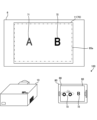
- FIG. 9 is a diagram showing a first example of changing the display mode of the marker image 71.
- the control device 4 performs a process of hiding the marker image 71 of the image 70, as shown in FIG. This process is an example of a process that reduces the visibility of the marker image 71.
- the marker image 71 is hidden, and the marker image 71 whose necessity has become low because the content image 73 has been played enough is hidden and the image 70
- the visibility of other parts of the content image 73 can be increased, and the number of times the content image 73 can be played back can be limited to create a premium feel.
- FIG. 10 is a diagram showing a second example of changing the display mode of the marker image 71.
- the control device 4 performs a process of thinning the marker image 71 of the image 70, as shown in FIG.
- the process of thinning the marker image 71 is, for example, a process of bringing the brightness and color of the marker image 71 closer to the brightness and color of the peripheral part (background) of the marker image 71 in the image 70.
- the process of thinning the marker image 71 may be a process of increasing the transmittance of the image 70.
- the process of thinning these marker images 71 is an example of a process of reducing the visibility of the marker images 71.
- the marker image 71 when the content image 73 has been played more than a predetermined number of times, by making the marker image 71 thinner, the marker image 71 that has become less necessary as the content image 73 has been played back becomes less noticeable, and other images 70 By increasing the visibility of the portion or making it difficult to detect the marker image 71 on the information terminal 80, it is possible to limit the number of times the content image 73 can be played back and create a premium feel.
- FIG. 11 is a diagram showing a third example of changing the display mode of the marker image 71.
- the control device 4 performs a process of reducing the size of the marker image 71 of the image 70, as shown in FIG. This process is an example of a process that reduces the visibility of the marker image 71.
- the marker image 71 when the content image 73 has been played more than a predetermined number of times, by making the marker image 71 smaller, the marker image 71 that has become less necessary as the content image 73 has been played back becomes less noticeable, and other images 70 By increasing the visibility of the portion or making it difficult to detect the marker image 71 on the information terminal 80, it is possible to limit the number of times the content image 73 is played back and create a premium feel.
- the control device 4 performs processing to lower the visibility of the marker image 71 of the image 70 in step S15 of FIG. Further, the control device 4 may perform a combination of the processes shown in FIGS. 9 to 11 in step S15 in FIG. 8. For example, the control device 4 may perform processing to make the marker image 71 of the image 70 thinner and to make the marker image 71 of the image 70 smaller in step S15 in FIG. 8 .
- FIG. 12 is a diagram showing a fourth example of changing the display mode of the marker image 71.
- the control device 4 performs a process of blinking the marker image 71 of the image 70 as shown in FIG.
- the control device 4 performs a process of superimposing an image (for example, a beam of light) in which the marker image 71 appears to be emitting light on the image 70.
- an image for example, a beam of light
- the marker image 71 is made to blink or the like, thereby making the observer aware that the content based on the marker image 71 (content image 73) is being reproduced a lot;
- An observer who has an information terminal that has not yet reproduced the content image 73 can be effectively urged to take an image of the marker image 71 and be guided to reproduce the content image 73.
- FIG. 13 is a diagram showing a fifth example of changing the display mode of the marker image 71.
- the control device 4 performs a process of changing the color of the marker image 71 of the image 70 to a more conspicuous color, or changing the font of the marker image 71 to a more conspicuous font, as shown in FIG. I do.
- Each of these processes is an example of a process that increases the visibility of the marker image 71.
- the viewer can be made aware that the content based on the marker image 71 (content image 73) is being played a lot; An observer who has an information terminal that has not yet reproduced the content image 73 can be effectively urged to take an image of the marker image 71 and be guided to reproduce the content image 73.
- FIG. 14 is a diagram showing a sixth example of changing the display mode of the marker image 71.
- the control device 4 performs a process of enlarging the marker image 71 of the image 70 as shown in FIG. This process is an example of a process that increases the visibility of the marker image 71.
- the viewer can recognize that the content based on the marker image 71 (content image 73) has been played a lot, and An observer who has an information terminal that is not reproducing the content image 73 can be effectively urged to take an image of the marker image 71, and can be guided to reproducing the content image 73.
- the control device 4 may perform processing to increase the visibility of the marker image 71 of the image 70 in step S15 of FIG. Further, the control device 4 may perform a combination of the processes shown in FIGS. 12 to 14 in step S15 in FIG. 8. For example, in step S15 of FIG. 8, the control device 4 may perform processing to blink the marker image 71 of the image 70, change the color of the marker image 71 of the image 70, and enlarge the marker image 71 of the image 70. good.
- control device 4 performs processing to lower the visibility of the marker image 71 of the image 70 shown in FIGS. 9 to 11, and processing to increase the visibility of the marker image 71 of the image 70 shown in FIGS. 12 to 14. You may also perform this in combination.
- the visibility of the marker image 71 associated with the content image 73 can be changed depending on the reproduction status of the content image 73.
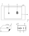
- FIG. 15 is a diagram showing an example of a display of an image representing information regarding the number of playbacks of the content image 73.
- the control device 4 may display information regarding the number of playbacks of the content image 73 in a superimposed manner on the image 70.
- the control device 4 includes, near the marker image 71 in the image 70, a reproduction number image 151 indicating the number of reproductions of the content image 73 associated with the marker image 71.
- the number of reproductions of the content image 73 is 256
- the reproduction number image 151 is an image indicating "256".
- the control device 4 may display the reproduction number image 151 in the examples of FIGS. 9 to 13.
- FIG. 16 is a diagram showing an example of a correspondence table for changing the display mode.
- FIG. 8 and the like a case has been described in which the display mode of the marker image 71 is changed once when the number of reproductions (information regarding the number of reproductions) satisfies the change condition, but the control device 4 , the display mode of the marker image 71 may be changed multiple times, for example in stages.
- the control device 4 can acquire the correspondence table 160 shown in FIG. 16.
- effects to be given to the marker image 71 are associated with each range of the number of reproductions. For example, in a range where the number of reproductions is from 0 to 100, there is no effect on the marker image 71. In a range where the number of reproductions is from 101 to 200, the effect given to the marker image 71 is A1. In the range where the number of reproductions is from 201 to 300, the effect given to the marker image 71 is A2. In the range of the number of reproductions from 301 to 400, the effect given to the marker image 71 is A3.
- the control device 4 changes the display mode of the marker image 71 in the image 70 based on the number of times the content image 73 has been played and the correspondence table 160. For example, if effects A1 to A3 are effects that make the size of the marker image 71 0.8 times, 0.6 times, and 0.4 times the original size, respectively, as the number of times the content image 73 is played increases, The size of the marker image 71 can be reduced in stages.
- control device 4 changes the display mode of the marker image 71 in the image 70 based on the number of times the content image 73 is played and a formula that can calculate the parameter of the effect given to the marker image 71 from the number of times the content image 73 is played. Good too.
- FIG. 17 is a diagram illustrating an example of a plurality of first images that can be played back by different information terminals.
- the marker image 72 may be associated with a content image 74 different from the content image 73, and the marker image 71 and the marker image 72 may use different information terminals that can reproduce the content.
- the content image 74 is a photographic image or an illustration image of a bird.
- the marker image 72 is an example of a first image associated with content.
- information terminals 80A and 80B shown in FIG. 17 are each similar to information terminal 80.
- the information terminal 80A plays back the content image 73 when the marker image 71 is detected from the captured image, it does not play back the content image 74 even when the marker image 72 is detected from the captured image.
- the information terminal 80A displays a superimposed image 90A in which the content image 73 is superimposed on the captured image.
- the information terminal 80B plays back the content image 74 when it detects the marker image 72 from the captured image, but does not play back the content image 73 even when it detects the marker image 71 from the captured image.
- the information terminal 80B displays a superimposed image 90B in which the content image 74 is superimposed on the captured image.
- the control device 4 acquires reproduction information for each of the marker images 71 and 72, that is, for each of the content image 73 and the content image 74. For example, the control device 4 obtains the number of times the content image 73 is played and the number of times the content image 74 is played.
- the control device 4 changes the display mode of the marker image 71 in the image 70 when the number of times the content image 73 is played satisfies the change condition, and changes the display mode of the marker image 71 in the image 70 when the number of times the content image 74 is played satisfies the change condition.
- the display mode of the marker image 72 in is changed. Thereby, the visibility of the marker image 71 can be changed according to the reproduction status of the content image 73, and the visibility of the marker image 72 can be changed according to the reproduction status of the content image 74.
- the changing conditions for changing the display mode of the marker image 71 and the changing conditions for changing the display mode of the marker image 72 may be different. Further, the method of changing the display mode of the marker image 71 and the method of changing the display mode of the marker image 72 may be different.
- FIG. 18 is a diagram illustrating an example of a display of attributes of an information terminal that can reproduce information.
- the control device 4 may include, in the image 70, an image indicating the attributes of the information terminal that can reproduce the associated content.
- each information terminal including the information terminals 80A and 80B may be provided with an electronic platinum ticket (A ticket) or a standard ticket (B ticket) depending on the contract or the like.
- an information terminal to which a platinum ticket is assigned detects a marker image 71, it plays back the content image 73, and an information terminal to which a standard ticket is assigned plays back a content image 74 when it detects a marker image 72.
- the information terminal 80A is given a platinum ticket
- the information terminal 80B is given a standard ticket.
- the control device 4 includes an attribute image 181 near the marker image 71 in the image 70, which indicates that the information terminal to which the platinum ticket has been given can reproduce the content.
- the attribute image 181 is a character image of "Platinum”.
- the control device 4 includes an attribute image 182 near the marker image 72 in the image 70, which indicates that the information terminal to which the standard ticket is attached can reproduce the content.
- the attribute image 182 is a character image of "Standard".
- the user can easily recognize the character image among the marker images 71 and 72 that allows the content to be played back on the information terminal that the user owns.
- the information regarding the number of reproductions of the content image 73 is not limited to the number of reproductions of the content image 73, but may be, for example, the cumulative number of reproductions of the content image 73.
- the cumulative number of reproductions of the content image 73 is the number of information terminals that have reproduced the content image 73.
- the control device 4 calculates the number of information terminals that are sources of the reproduction information received after step S11.
- the change condition in step S14 is, for example, that the cumulative number of reproductions of the content image 73 exceeds a predetermined number.
- the information regarding the number of reproductions of the content image 73 may be, for example, the number of devices that simultaneously reproduce the content image 73.
- the number of simultaneous reproductions of the content image 73 is the number of information terminals that are simultaneously reproducing the content image 73.
- the control device 4 determines whether or not the information terminal that is the source of the playback information is currently playing back the content image 73, thereby providing information regarding the number of playbacks of the content image 73.
- the number of devices that simultaneously reproduce the content image 73 is calculated.
- the control device 4 determines whether or not the information terminal that is the source of the reproduction information is currently reproducing the content image 73, and starts the reproduction of the content image 73 for each information terminal that is the source of the reproduction information. This is done by specifying the time and end time.
- the playback start time of the content image 73 may be specified based on the time when the playback information is received, or may be specified from the playback information by including the playback start time of the content image 73 in the playback information.
- the end time of the reproduction of the content image 73 may be specified from the start time of the reproduction of the content image 73 if the reproduction time length of the content image 73 is constant, or the end time of the reproduction of the content image 73 may be specified in the reproduction information. By including it, it may be specified from the playback information.
- the change condition in step S14 is, for example, that the number of devices that simultaneously reproduce the content image 73 exceeds a predetermined number.
- the control device 4 suppresses hunting in the display mode of the marker image 71.
- the display mode of the marker image 71 may be changed to gradually follow the change in information regarding the number of reproductions of the content image 73.
- the information regarding the number of playbacks of the content image 73 may be information calculated from a plurality of information among the number of playbacks of the content image 73, the cumulative number of playbacks of the content image 73, and the number of simultaneous playbacks of the content image 73. .
- the information terminal 80 plays back the content image 73 by reading the marker image 71, but the method for playing back the content image 73 is not limited to this.
- the image 70 includes a guide image (first image) that prompts reproduction of the content image 73 instead of or together with the marker image 71, and the user of the information terminal 80
- the content image 73 may be played back by operating the information terminal 80 according to the following.
- the first image with which content is associated is not limited to a character image, but may also be a graphic image showing a specific shape, or a two-dimensional image. It may also be a pattern image of a code or the like.
- FIG. 19 is a schematic diagram showing another external configuration of the projection device 10.
- FIG. 20 is a schematic cross-sectional view of the optical unit 106 of the projection apparatus 10 shown in FIG. 19.
- the same parts as those shown in FIGS. 4 and 5 are designated by the same reference numerals, and the description thereof will be omitted.
- the optical unit 106 includes a first member 102 supported by the main body 101 and a second member 103 supported by the first member 102.
- the first member 102 and the second member 103 may be an integrated member.
- the optical unit 106 includes, in addition to the first member 102, a second member 103 having a hollow portion 3A connected to the hollow portion 2A of the first member 102, and a first member disposed in the hollow portion 2A.
- the opening 2a and the opening 2b of the first member 102 are formed in planes perpendicular to each other.
- the projection optical system 23 shown in FIGS. 19 and 20 includes a reflection member 122, a second optical system 31, a reflection member 32, and It is constituted by a third optical system 33.
- the optical axis K is bent twice and turned back.
- the first optical system 121, the reflecting member 122, the second optical system 31, the reflecting member 32, the third optical system 33, and the lens 34 are arranged along the optical axis K in this order from the light modulating section 22 side.
- the first optical system 121 guides the light incident on the first member 102 from the main body 101 and traveling in the direction X1 to the reflecting member 122.
- the reflecting member 122 reflects the light incident from the first optical system 121 in the direction Y1.
- the reflecting member 122 is composed of, for example, a mirror.
- the first member 102 has an opening 2b formed on the optical path of the light reflected by the reflecting member 122, and the reflected light passes through the opening 2b and advances to the hollow portion 3A of the second member 103.
- the second member 103 is a member having a substantially L-shaped cross-sectional outline, and has an opening 3a formed at a position facing the opening 2b of the first member 102.
- the light from the main body portion 101 that has passed through the opening 2b of the first member 102 is incident on the hollow portion 3A of the second member 103 through this opening 3a.
- the cross-sectional shapes of the first member 102 and the second member 103 are arbitrary, and are not limited to those described above.
- the second optical system 31 includes at least one lens and guides the light incident from the first member 102 to the reflecting member 32.
- the reflecting member 32 reflects the light incident from the second optical system 31 in the direction X2 and guides it to the third optical system 33.
- the reflecting member 32 is formed of, for example, a mirror.
- the third optical system 33 includes at least one lens, and guides the light reflected by the reflecting member 32 to the lens 34.
- the lens 34 is arranged at the end of the second member 103 in the direction X2 so as to close the opening 3c formed at this end.
- the lens 34 projects the light incident from the third optical system 33 onto the projection target 6.
- FIG. 20 shows a state in which the first member 102 is moved to the maximum extent in the direction Y1 by the first shift mechanism 105. From the state shown in FIG. 20, by moving the first member 102 in the direction Y2 by the first shift mechanism 105, the relative position between the center of the image formed by the light modulating section 22 and the optical axis K changes. , the image G1 projected onto the projection object 6 can be shifted in the direction Y1.
- the projection direction changing mechanism 104 is a rotation mechanism that rotatably connects the second member 103 to the first member 102.
- the projection direction changing mechanism 104 allows the second member 103 to rotate around a rotation axis (specifically, the optical axis K) extending in the Y direction.
- a rotation axis specifically, the optical axis K
- the projection direction changing mechanism 104 is not limited to the arrangement position shown in FIG. 20 as long as it can rotate the optical system. Further, the number of rotation mechanisms is not limited to one, and a plurality of rotation mechanisms may be provided.
- control device of the present invention is applied to the control device 4 of the projection device 10
- the configuration is not limited to this.
- FIG. 21 is a diagram showing a modification of the system 100.
- a system 100 shown in FIG. 21 includes an information terminal 110 in addition to the configuration of the system 100 shown in FIG.
- the control device of the present invention may be applied to the information terminal 110.
- the information terminal 110 is an information terminal that can communicate with the projection device 10 directly or indirectly. Communication between the information terminal 110 and the projection device 10 may be wired communication or wireless communication.
- the information terminal 110 executes various controls by the control device 4 described above by communicating with the projection device 10 .
- the information terminal 110 is a notebook personal computer, but the information terminal 110 can be any of various information terminals such as a desktop personal computer, a smartphone, or a tablet terminal.
- the reproduction information of the content image 73 is received from an information terminal such as the information terminal 80, and based on the received reproduction information, the marker image 71 in the image 70 is Performs control to change the display mode of.
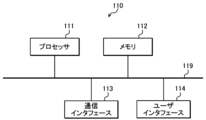
- FIG. 22 is a diagram showing an example of the hardware configuration of the information terminal 110.
- the information terminal 110 shown in FIG. 1 includes a processor 111, a memory 112, a communication interface 113, and a user interface 114, as shown in FIG.
- Processor 111, memory 112, communication interface 113, and user interface 114 are connected by bus 119, for example.
- the processor 111, memory 112, communication interface 113, and user interface 114 have the same configuration as the processor 81, memory 82, communication interface 83, and user interface 84 shown in FIG. 6, respectively.
- images such as content images 73 and 74 have been described as examples of content associated with the image 70, the content associated with the image 70 is not limited to images.
- the content associated with the image 70 may be content other than images that can be played back by the information terminal 80, such as audio and vibration.
Abstract
Provided are a control device, a control method, a control program, and a system that make it possible to change the visibility of an image with which a content is associated, the visibility being changed depending on a reproduction situation of the content. A control device (4) causes an image (70) to be projected from a projection device (10), the image (70) including a marker image (71) with which a content image (73) is associated. The control device (4) also acquires reproduction information on the reproduction of the content image (73) by an information terminal (80) and changes a display mode of the marker image (71) in the image (70) on the basis of the reproduction information.
Description
本発明は、制御装置、制御方法、制御プログラム、及びシステムに関する。
The present invention relates to a control device, a control method, a control program, and a system.
特許文献1には、拡張現実のための方法において、マーカーを含む現実世界イメージが生成され、マーカーは現実世界イメージから検出され、検出されたマーカーに対応するオブジェクトイメージが現実世界イメージと組み合わされ、組み合わされたイメージが表示されることが記載されている。
Patent Document 1 discloses a method for augmented reality in which a real world image including a marker is generated, the marker is detected from the real world image, an object image corresponding to the detected marker is combined with the real world image, It is stated that the combined image will be displayed.
特許文献2には、商品が陳列されていない陳列用領域を含む現実空間を撮像した画像において、その現実空間における陳列用領域に商品画像を重畳表示させ、現実空間において重畳表示された商品画像に対してユーザが第1の行為を行うと、その商品画像に対応する商品を注文するための処理を行う情報処理装置が記載されている。
Patent Document 2 discloses that in an image taken of a real space including a display area where no products are displayed, a product image is displayed superimposed on the display area in the real space, and the product image superimposed in the real space is In response, when a user performs a first action, an information processing apparatus is described that performs processing for ordering a product corresponding to the product image.
特許文献3には、表示部の画面内に特定の対象物がフレームインしたことを認識し、フレームインの認識回数が予め設定した認識回数に一致した場合に、認識回数に応じた所定の表示を行う画像処理装置が記載されている。
Patent Document 3 discloses that when it is recognized that a specific object has entered the frame within the screen of the display unit, and the number of frame-in recognitions matches a preset number of recognitions, a predetermined display is displayed according to the number of recognitions. An image processing device that performs this is described.
特許文献4には、氏名とその周部に配置されたマーカーとを含む印影を撮像し、撮像された画像から印影画像を抽出し、その印影画像から印影に含まれたマーカーを抽出し、抽出したマーカーに関連付けられた生成画像を生成画像データベースから選択して生成する携帯端末装置が記載されている。
Patent Document 4 discloses a method for capturing an image of a seal including a name and a marker placed around the name, extracting a seal image from the captured image, extracting a marker included in the seal from the seal image, and extracting the image. A mobile terminal device is described that selects and generates a generated image associated with a marker from a generated image database.
本開示の技術に係る1つの実施形態は、コンテンツが対応付けられた画像の視認性をそのコンテンツの再生状況に応じて変更することができる制御装置、制御方法、制御プログラム、及びシステムを提供する。
One embodiment of the technology of the present disclosure provides a control device, a control method, a control program, and a system that can change the visibility of an image associated with content depending on the playback status of the content. .
(1)
プロセッサを備える制御装置であって、
上記プロセッサは、
コンテンツが対応付けられた第1画像を含む第2画像を投影装置から投影させ、
情報端末による上記コンテンツの再生に関する再生情報を取得し、
上記再生情報に基づいて上記第2画像における上記第1画像の表示態様を変更する、
制御装置。 (1)
A control device comprising a processor,
The above processor is
projecting a second image including the first image associated with the content from a projection device;
Obtain playback information regarding playback of the above content by the information terminal,
changing the display mode of the first image in the second image based on the reproduction information;
Control device.
(2)
(1)に記載の制御装置であって、
上記第1画像の表示態様の変更は、上記第1画像の視認性を変更する処理である、
制御装置。 (2)
The control device according to (1),
Changing the display mode of the first image is a process of changing the visibility of the first image,
Control device.
(1)に記載の制御装置であって、
上記第1画像の表示態様の変更は、上記第1画像の視認性を変更する処理である、
制御装置。 (2)
The control device according to (1),
Changing the display mode of the first image is a process of changing the visibility of the first image,
Control device.
(3)
(2)に記載の制御装置であって、
上記第1画像の表示態様の変更は、上記第1画像の視認性を下げる処理である、
制御装置。 (3)
The control device according to (2),
Changing the display mode of the first image is a process of lowering the visibility of the first image,
Control device.
(2)に記載の制御装置であって、
上記第1画像の表示態様の変更は、上記第1画像の視認性を下げる処理である、
制御装置。 (3)
The control device according to (2),
Changing the display mode of the first image is a process of lowering the visibility of the first image,
Control device.
(4)
(2)に記載の制御装置であって、
上記第1画像の表示態様の変更は、上記第1画像の視認性を上げる処理である、
制御装置。 (4)
The control device according to (2),
Changing the display mode of the first image is a process of increasing the visibility of the first image,
Control device.
(2)に記載の制御装置であって、
上記第1画像の表示態様の変更は、上記第1画像の視認性を上げる処理である、
制御装置。 (4)
The control device according to (2),
Changing the display mode of the first image is a process of increasing the visibility of the first image,
Control device.
(5)
(1)から(4)のいずれか1項に記載の制御装置であって、
上記再生情報は、上記コンテンツの再生数に関する情報である、
制御装置。 (5)
The control device according to any one of (1) to (4),
The playback information is information regarding the number of playbacks of the content,
Control device.
(1)から(4)のいずれか1項に記載の制御装置であって、
上記再生情報は、上記コンテンツの再生数に関する情報である、
制御装置。 (5)
The control device according to any one of (1) to (4),
The playback information is information regarding the number of playbacks of the content,
Control device.
(6)
(5)に記載の制御装置であって、
上記コンテンツの再生数に関する情報は、1つ以上の情報端末が上記コンテンツを再生した回数を示す情報を含む、
制御装置。 (6)
The control device according to (5),
The information regarding the number of times the content has been played includes information indicating the number of times the content has been played by one or more information terminals;
Control device.
(7)
(5)又は(6)に記載の制御装置であって、
上記コンテンツの再生数に関する情報は、上記コンテンツの再生を行った情報端末の数を示す情報を含む、
制御装置。 (7)
The control device according to (5) or (6),
The information regarding the number of playbacks of the content includes information indicating the number of information terminals that have played the content;
Control device.
(8)
(5)から(7)のいずれか1項に記載の制御装置であって、
上記コンテンツの再生数に関する情報は、上記コンテンツを同時に再生している情報端末の数を示す情報を含む、
制御装置。 (8)
The control device according to any one of (5) to (7),
The information regarding the number of playbacks of the content includes information indicating the number of information terminals that are simultaneously playing the content;
Control device.
(9)
(5)から(8)のいずれか1項に記載の制御装置であって、
上記第2画像は、上記コンテンツの再生数に関する情報を表す画像を含む、
制御装置。 (9)
The control device according to any one of (5) to (8),
The second image includes an image representing information regarding the number of plays of the content,
Control device.
(5)から(8)のいずれか1項に記載の制御装置であって、
上記第2画像は、上記コンテンツの再生数に関する情報を表す画像を含む、
制御装置。 (9)
The control device according to any one of (5) to (8),
The second image includes an image representing information regarding the number of plays of the content,
Control device.
(10)
(1)から(9)のいずれか1項に記載の制御装置であって、
上記第1画像は、再生可能な情報端末が異なる複数の第1画像を含み、
上記プロセッサは、上記複数の第1画像について上記再生情報を取得する、
制御装置。 (10)
The control device according to any one of (1) to (9),
The first image includes a plurality of first images that can be played back by different information terminals,
The processor obtains the reproduction information regarding the plurality of first images.
Control device.
(11)
制御装置のプロセッサが、
コンテンツが対応付けられた第1画像を含む第2画像を投影装置から投影させ、
情報端末による上記コンテンツの再生に関する再生情報を取得し、
上記再生情報に基づいて上記第2画像における上記第1画像の表示態様を変更する、
制御方法。 (11)
The controller's processor
projecting a second image including the first image associated with the content from a projection device;
Obtain playback information regarding playback of the above content by the information terminal,
changing the display mode of the first image in the second image based on the reproduction information;
Control method.
(12)
制御装置のプロセッサに、
コンテンツが対応付けられた第1画像を含む第2画像を投影装置から投影させ、
情報端末による上記コンテンツの再生に関する再生情報を取得し、
上記再生情報に基づいて上記第2画像における上記第1画像の表示態様を変更する、
処理を実行させるための制御プログラム。 (12)
In the controller's processor,
projecting a second image including the first image associated with the content from a projection device;
Obtain playback information regarding playback of the above content by the information terminal,
changing the display mode of the first image in the second image based on the reproduction information;
A control program for executing processing.
(13)
コンテンツが対応付けられた第1画像を含む第2画像を投影装置から投影させ、情報端末による上記コンテンツの再生に関する再生情報を取得し、上記再生情報に基づいて上記第2画像における上記第1画像の表示態様を変更する制御装置と、
上記投影装置と、
上記情報端末と、
を含むシステム。 (13)
Projecting a second image including a first image associated with content from a projection device, acquiring playback information regarding playback of the content by an information terminal, and based on the playback information, the first image in the second image. a control device that changes the display mode of the
The above projection device;
The above information terminal,
system containing.
本発明によれば、コンテンツが対応付けられた画像の視認性をそのコンテンツの再生状況に応じて変更することのできる制御装置、制御方法、制御プログラム、及びシステムを提供することができる。
According to the present invention, it is possible to provide a control device, a control method, a control program, and a system that can change the visibility of an image associated with content depending on the playback status of the content.
以下、本発明の実施形態の一例について、図面を参照して説明する。
Hereinafter, an example of an embodiment of the present invention will be described with reference to the drawings.
(実施形態)
<実施形態のシステム100>
図1は、実施形態のシステム100の一例を示す図である。図1に示すように、システム100は、投影装置10と、情報端末80と、を含む。本発明における制御装置は、例えば投影装置10に適用される。投影装置10は、投影対象物6に対する投影が可能な投影装置である。 (Embodiment)
<System 100 of embodiment>
FIG. 1 is a diagram illustrating an example of asystem 100 according to an embodiment. As shown in FIG. 1, the system 100 includes a projection device 10 and an information terminal 80. The control device in the present invention is applied to the projection device 10, for example. The projection device 10 is a projection device capable of projecting onto the projection target 6.
<実施形態のシステム100>
図1は、実施形態のシステム100の一例を示す図である。図1に示すように、システム100は、投影装置10と、情報端末80と、を含む。本発明における制御装置は、例えば投影装置10に適用される。投影装置10は、投影対象物6に対する投影が可能な投影装置である。 (Embodiment)
<
FIG. 1 is a diagram illustrating an example of a
投影対象物6は、投影装置10によって投影画像が表示される投影面を有するスクリーンや壁などの物体である。図1に示す例では、投影対象物6の投影面は矩形の平面である。図1における投影対象物6の上下左右が実際の投影対象物6の上下左右であるとする。
The projection object 6 is an object such as a screen or a wall that has a projection surface on which a projected image is displayed by the projection device 10. In the example shown in FIG. 1, the projection surface of the projection object 6 is a rectangular plane. It is assumed that the top, bottom, right and left of the projection target 6 in FIG. 1 are the top, bottom, left and right of the actual projection target 6.
一点鎖線で図示する投影範囲11は、投影対象物6のうち、投影装置10により投影光が照射される領域である。投影範囲11は、投影装置10により投影が可能な投影可能範囲の一部又は全部である。図1に示す例では、投影範囲11は矩形である。
A projection range 11 illustrated by a dashed line is an area of the projection target 6 that is irradiated with projection light by the projection device 10. The projection range 11 is part or all of the projectable range that can be projected by the projection device 10 . In the example shown in FIG. 1, the projection range 11 is rectangular.
情報端末80は、スマートフォンやタブレット端末などの、撮像部(例えば図6の撮像モジュール85)及び表示部86を有する情報端末である。情報端末80には、撮像部により得られた撮像画像に特定のマーカー画像が含まれている場合に、その撮像画像に対して、予め定められた拡張現実(AR:Augmented Reality)コンテンツを重畳した重畳画像を表示部86により表示させるアプリケーションが記憶(インストール)されている。
The information terminal 80 is an information terminal, such as a smartphone or a tablet terminal, that has an imaging section (for example, the imaging module 85 in FIG. 6) and a display section 86. When the captured image obtained by the imaging unit includes a specific marker image, the information terminal 80 superimposes predetermined augmented reality (AR) content on the captured image. An application for displaying a superimposed image on the display unit 86 is stored (installed).
<投影装置10の構成>
図2は、投影装置10の構成の一例を示す図である。図2に示すように、投影装置10は、例えば、投影部1と、制御装置4と、操作受付部2と、を備える。投影装置10は、さらに通信部5を備えてもよい。投影部1は、例えば液晶プロジェクタ又はLCOS(Liquid Crystal On Silicon)を用いたプロジェクタ等によって構成される。以下では、投影部1が液晶プロジェクタであるものとして説明する。 <Configuration ofprojection device 10>
FIG. 2 is a diagram showing an example of the configuration of theprojection device 10. As shown in FIG. 2, the projection device 10 includes, for example, a projection section 1, a control device 4, and an operation reception section 2. The projection device 10 may further include a communication section 5. The projection unit 1 is configured by, for example, a liquid crystal projector or a projector using LCOS (Liquid Crystal On Silicon). The following description will be made assuming that the projection unit 1 is a liquid crystal projector.
図2は、投影装置10の構成の一例を示す図である。図2に示すように、投影装置10は、例えば、投影部1と、制御装置4と、操作受付部2と、を備える。投影装置10は、さらに通信部5を備えてもよい。投影部1は、例えば液晶プロジェクタ又はLCOS(Liquid Crystal On Silicon)を用いたプロジェクタ等によって構成される。以下では、投影部1が液晶プロジェクタであるものとして説明する。 <Configuration of
FIG. 2 is a diagram showing an example of the configuration of the
制御装置4は、本発明の制御装置の一例である。制御装置4は、投影装置10による投影の制御を行う。制御装置4は、各種のプロセッサにより構成される制御部と、各部と通信するための通信インタフェース(図示省略)と、ハードディスク、SSD(Solid State Drive)、又はROM(Read Only Memory)等の記憶媒体4aと、を含む装置であり、投影部1を統括制御する。制御装置4の制御部の各種のプロセッサとしては、プログラムを実行して各種処理を行う汎用的なプロセッサであるCPU(Central Processing Unit)、FPGA(Field Programmable Gate Array)等の製造後に回路構成を変更可能なプロセッサであるプログラマブルロジックデバイス(Programmable Logic Device:PLD)、又はASIC(Application Specific Integrated Circuit)等の特定の処理を実行させるために専用に設計された回路構成を有するプロセッサである専用電気回路等が含まれる。
The control device 4 is an example of the control device of the present invention. The control device 4 controls projection by the projection device 10 . The control device 4 includes a control section composed of various processors, a communication interface (not shown) for communicating with each section, and a storage medium such as a hard disk, SSD (Solid State Drive), or ROM (Read Only Memory). 4a, and centrally controls the projection unit 1. Various processors in the control unit of the control device 4 include a CPU (Central Processing Unit), which is a general-purpose processor that executes programs and performs various processes, and an FPGA (Field Programmable Gate Array), whose circuit configurations are changed after manufacturing. Designed exclusively to execute specific processing such as possible processor programmable logic devices (PROGRAMMABLE LOGIC DEVICE: PLD) or ASIC (Application Specific INTEGRATED CIRCUIT). A dedicated electric circuit, which is a processor with a circuit configuration, etc. is included.
これら各種のプロセッサの構造は、より具体的には、半導体素子等の回路素子を組み合わせた電気回路である。制御装置4の制御部は、各種のプロセッサのうちの1つで構成されてもよいし、同種又は異種の2つ以上のプロセッサの組み合わせ(例えば、複数のFPGAの組み合わせ又はCPUとFPGAの組み合わせ)で構成されてもよい。
More specifically, the structure of these various processors is an electric circuit that combines circuit elements such as semiconductor elements. The control unit of the control device 4 may be configured with one of various processors, or a combination of two or more processors of the same type or different types (for example, a combination of multiple FPGAs or a combination of a CPU and an FPGA). It may be composed of.
操作受付部2は、ユーザからの各種の操作を受け付けることにより、ユーザからの指示(ユーザ指示)を検出する。操作受付部2は、制御装置4に設けられたボタン、キー、ジョイスティック等であってもよいし、制御装置4の遠隔操作を行うリモートコントローラからの信号を受け付ける受信部等であってもよい。
The operation reception unit 2 detects instructions from the user (user instructions) by accepting various operations from the user. The operation reception section 2 may be a button, a key, a joystick, etc. provided on the control device 4, or may be a reception section or the like that receives a signal from a remote controller that remotely controls the control device 4.
通信部5は、他の装置との間で通信が可能な通信インタフェースである。通信部5は、有線通信を行う有線通信インタフェースであってもよいし、無線通信を行う無線通信インタフェースであってもよい。
The communication unit 5 is a communication interface that can communicate with other devices. The communication unit 5 may be a wired communication interface that performs wired communication, or may be a wireless communication interface that performs wireless communication.
なお、投影部1、制御装置4、操作受付部2、及び通信部5は、例えば一個の装置により実現される(例えば図4,図5参照)。又は、投影部1、制御装置4、操作受付部2、及び通信部5は、互いに通信を行うことにより連携可能な複数の装置により実現されてもよい。
Note that the projection unit 1, the control device 4, the operation reception unit 2, and the communication unit 5 are realized by, for example, one device (see, for example, FIGS. 4 and 5). Alternatively, the projection unit 1, the control device 4, the operation reception unit 2, and the communication unit 5 may be realized by a plurality of devices that can cooperate by communicating with each other.
<投影部1の内部構成>
図3は、投影部1の内部構成の一例を示す模式図である。図2に示した投影装置10の投影部1は、図3に示すように、光源21と、光変調部22と、投影光学系23と、制御回路24と、を備える。光源21は、レーザ又はLED(Light Emitting Diode)等の発光素子を含み、例えば白色光を出射する。 <Internal configuration ofprojection unit 1>
FIG. 3 is a schematic diagram showing an example of the internal configuration of theprojection section 1. As shown in FIG. The projection section 1 of the projection apparatus 10 shown in FIG. 2 includes a light source 21, a light modulation section 22, a projection optical system 23, and a control circuit 24, as shown in FIG. The light source 21 includes a light emitting element such as a laser or an LED (Light Emitting Diode), and emits, for example, white light.
図3は、投影部1の内部構成の一例を示す模式図である。図2に示した投影装置10の投影部1は、図3に示すように、光源21と、光変調部22と、投影光学系23と、制御回路24と、を備える。光源21は、レーザ又はLED(Light Emitting Diode)等の発光素子を含み、例えば白色光を出射する。 <Internal configuration of
FIG. 3 is a schematic diagram showing an example of the internal configuration of the
光変調部22は、光源21から出射されて図示省略の色分離機構によって赤、青、緑の3色に分離された各色光を、画像情報に基づいて変調して各色画像を出射する3つの液晶パネル(光変調素子)と、3つの液晶パネルから出射された各色画像を混合して同一方向に出射するダイクロイックプリズムと、によって構成される。この3つの液晶パネルにそれぞれ赤、青、緑のフィルタを搭載し、光源21から出射された白色光を、各液晶パネルにて変調して各色画像を出射させてもよい。
The light modulation unit 22 modulates each color light emitted from the light source 21 and separated into three colors of red, blue, and green by a color separation mechanism (not shown) based on image information, and outputs each color image. It is composed of a liquid crystal panel (light modulation element) and a dichroic prism that mixes each color image emitted from the three liquid crystal panels and emits it in the same direction. Red, blue, and green filters may be mounted on each of these three liquid crystal panels, and the white light emitted from the light source 21 may be modulated by each liquid crystal panel to emit each color image.
投影光学系23は、光源21及び光変調部22からの光が入射されるものであり、少なくとも1つのレンズを含む、例えばリレー光学系によって構成されている。投影光学系23を通過した光は投影対象物6に投影される。
The projection optical system 23 receives light from the light source 21 and the light modulation section 22, and is configured by, for example, a relay optical system including at least one lens. The light passing through the projection optical system 23 is projected onto the projection target 6.
投影対象物6のうち、光変調部22の全範囲を透過する光が照射される領域が、投影部1により投影が可能な投影可能範囲となる。この投影可能範囲のうち、光変調部22から実際に透過する光が照射される領域が投影部1の投影範囲11となる。例えば、光変調部22のうち光が透過する領域の大きさ、位置、及び形状を制御することにより、投影可能範囲において、投影部1の投影範囲の大きさ、位置、及び形状が変化する。
A region of the projection target 6 that is irradiated with light that passes through the entire range of the light modulation section 22 becomes a projectable range that can be projected by the projection section 1. Of this projectable range, the area to which the light actually transmitted from the light modulation section 22 is irradiated becomes the projection range 11 of the projection section 1 . For example, by controlling the size, position, and shape of a region of the light modulation section 22 through which light passes, the size, position, and shape of the projection range of the projection section 1 are changed in the projectable range.
制御回路24は、制御装置4から入力される表示用データに基づいて、光源21、光変調部22、及び投影光学系23を制御することにより、投影対象物6にこの表示用データに基づく画像を投影させる。制御回路24に入力される表示用データは、赤表示用データと、青表示用データと、緑表示用データとの3つによって構成される。
The control circuit 24 controls the light source 21, the light modulation section 22, and the projection optical system 23 based on the display data input from the control device 4, so that an image based on the display data is displayed on the projection target 6. to be projected. The display data input to the control circuit 24 is composed of three pieces: red display data, blue display data, and green display data.
また、制御回路24は、制御装置4から入力される命令に基づいて、投影光学系23を変化させることにより、投影部1の投影範囲の拡大や縮小を行う。また、制御装置4は、操作受付部2によって受け付けられたユーザからの操作に基づいて投影光学系23を変化させることにより、投影部1の投影範囲の移動を行ってもよい。
Furthermore, the control circuit 24 expands or reduces the projection range of the projection unit 1 by changing the projection optical system 23 based on commands input from the control device 4. Further, the control device 4 may move the projection range of the projection unit 1 by changing the projection optical system 23 based on a user's operation accepted by the operation reception unit 2.
また、投影装置10は、投影光学系23のイメージサークルを維持しつつ、投影部1の投影範囲を機械的又は光学的に移動させるシフト機構を備える。投影光学系23のイメージサークルは、投影光学系23に入射した投影光が、光量落ち、色分離、周辺湾曲などの点から適正に投影光学系23を通過する領域である。
Furthermore, the projection device 10 includes a shift mechanism that mechanically or optically moves the projection range of the projection unit 1 while maintaining the image circle of the projection optical system 23. The image circle of the projection optical system 23 is an area in which the projection light incident on the projection optical system 23 passes through the projection optical system 23 appropriately in terms of light falloff, color separation, peripheral curvature, and the like.
シフト機構は、光学系シフトを行う光学系シフト機構と、電子シフトを行う電子シフト機構と、の少なくともいずれかにより実現される。
The shift mechanism is realized by at least one of an optical system shift mechanism that shifts the optical system and an electronic shift mechanism that shifts the electronic system.
光学系シフト機構は、例えば、投影光学系23を光軸に垂直な方向に移動させる機構(例えば図5,20参照)、又は、投影光学系23を移動させる代わりに光変調部22を光軸に垂直な方向に移動させる機構である。また、光学系シフト機構は、投影光学系23の移動と光変調部22の移動とを組み合わせて行うものであってもよい。
The optical system shift mechanism is, for example, a mechanism that moves the projection optical system 23 in a direction perpendicular to the optical axis (see, for example, FIGS. 5 and 20), or a mechanism that moves the optical modulator 22 along the optical axis instead of moving the projection optical system 23. This is a mechanism that moves the object in a direction perpendicular to the direction. Further, the optical system shift mechanism may be a mechanism that combines the movement of the projection optical system 23 and the movement of the light modulation section 22.
電子シフト機構は、光変調部22において光を透過させる範囲を変化させることによる疑似的な投影範囲のシフトを行う機構である。
The electronic shift mechanism is a mechanism that performs a pseudo projection range shift by changing the range through which light is transmitted in the light modulation section 22.
また、投影装置10は、投影光学系23のイメージサークルとともに投影範囲を移動させる投影方向変更機構を備えてもよい。投影方向変更機構は、機械的な回転で投影部1の向きを変更することにより、投影部1の投影方向を変化させる機構である(例えば図20参照)。
Furthermore, the projection device 10 may include a projection direction changing mechanism that moves the projection range together with the image circle of the projection optical system 23. The projection direction changing mechanism is a mechanism that changes the projection direction of the projection section 1 by changing the direction of the projection section 1 by mechanical rotation (see, for example, FIG. 20).
<投影装置10の機械的構成>
図4は、投影装置10の外観構成の一例を示す図である。図5は、図4に示す投影装置10の光学ユニット106の一部断面模式図である。図5は、図4に示した本体部101から出射される光の光路に沿った面での断面を示している。 <Mechanical configuration ofprojection device 10>
FIG. 4 is a diagram showing an example of the external configuration of theprojection device 10. FIG. 5 is a schematic partial cross-sectional view of the optical unit 106 of the projection apparatus 10 shown in FIG. 4. FIG. 5 shows a cross section taken along the optical path of light emitted from the main body 101 shown in FIG.
図4は、投影装置10の外観構成の一例を示す図である。図5は、図4に示す投影装置10の光学ユニット106の一部断面模式図である。図5は、図4に示した本体部101から出射される光の光路に沿った面での断面を示している。 <Mechanical configuration of
FIG. 4 is a diagram showing an example of the external configuration of the
図4に示すように、投影装置10は、本体部101と、本体部101から突出して設けられた光学ユニット106と、を備える。図4に示す構成において、操作受付部2と、制御装置4と、投影部1における光源21、光変調部22、及び制御回路24と、通信部5と、は本体部101に設けられる。投影部1における投影光学系23は光学ユニット106に設けられる。
As shown in FIG. 4, the projection device 10 includes a main body 101 and an optical unit 106 provided to protrude from the main body 101. In the configuration shown in FIG. 4, the operation reception section 2, the control device 4, the light source 21, the light modulation section 22, and the control circuit 24 in the projection section 1, and the communication section 5 are provided in the main body section 101. The projection optical system 23 in the projection section 1 is provided in the optical unit 106.
光学ユニット106は、本体部101に支持される第1部材102を備える。光学ユニット106は、本体部101に着脱自在に構成(換言すると交換可能に構成)されていてもよい。
The optical unit 106 includes a first member 102 supported by the main body 101. The optical unit 106 may be configured to be detachably attached to the main body portion 101 (in other words, configured to be replaceable).
本体部101は、図5に示すように、光学ユニット106と連結される部分に光を通すための開口15aが形成された筐体15を有する。
As shown in FIG. 5, the main body portion 101 has a casing 15 in which an opening 15a for passing light is formed in a portion connected to the optical unit 106.
図4に示すように、本体部101の筐体15の内部には、光源21と、光源21から出射される光を入力画像データに基づいて空間変調して画像を生成する光変調部22(図3参照)を含む光変調ユニット12と、が設けられている。光源21から出射された光は、光変調ユニット12の光変調部22に入射され、光変調部22によって空間変調されて出射される。
As shown in FIG. 4, inside the casing 15 of the main body section 101, there is a light source 21 and a light modulation section 22 (which generates an image by spatially modulating the light emitted from the light source 21 based on input image data). (see FIG. 3). The light emitted from the light source 21 enters the light modulation section 22 of the light modulation unit 12, is spatially modulated by the light modulation section 22, and is emitted.
図5に示すように、光変調ユニット12によって空間変調された光によって形成される画像は、筐体15の開口15aを通過して光学ユニット106に入射され、投影対象物6に投影されて、画像G1が観察者から視認可能となる。
As shown in FIG. 5, the image formed by the light spatially modulated by the light modulation unit 12 passes through the opening 15a of the housing 15, enters the optical unit 106, is projected onto the projection object 6, Image G1 becomes visible to the observer.
図5に示すように、光学ユニット106は、本体部101の内部と繋がる中空部2Aを有する第1部材102と、中空部2Aに配置された第1光学系121と、レンズ34と、第1シフト機構105と、を備える。
As shown in FIG. 5, the optical unit 106 includes a first member 102 having a hollow portion 2A connected to the inside of the main body 101, a first optical system 121 disposed in the hollow portion 2A, a lens 34, and a first member 102. A shift mechanism 105 is provided.
第1部材102は、断面外形が一例として矩形の部材であり、開口2aと開口2bが互いに平行な面に形成されている。第1部材102は、本体部101の開口15aと対面する位置に開口2aが配置される状態にて、本体部101によって支持されている。本体部101の光変調ユニット12の光変調部22から射出された光は、開口15a及び開口2aを通って第1部材102の中空部2Aに入射される。
The first member 102 is a member having a rectangular cross-sectional outer shape, for example, and the opening 2a and the opening 2b are formed in planes parallel to each other. The first member 102 is supported by the main body 101 with the opening 2a facing the opening 15a of the main body 101. Light emitted from the light modulation section 22 of the light modulation unit 12 of the main body section 101 is incident on the hollow section 2A of the first member 102 through the opening 15a and the opening 2a.
本体部101から中空部2Aに入射される光の入射方向を方向X1と記載し、方向X1の逆方向を方向X2と記載し、方向X1と方向X2を総称して方向Xと記載する。また、図5において、紙面手前から奥に向かう方向とその逆方向を方向Zと記載する。方向Zのうち、紙面手前から奥に向かう方向を方向Z1と記載し、紙面奥から手前に向かう方向を方向Z2と記載する。
The direction of incidence of light entering the hollow portion 2A from the main body portion 101 is referred to as a direction X1, the direction opposite to the direction X1 is referred to as a direction X2, and the directions X1 and X2 are collectively referred to as a direction X. Further, in FIG. 5, the direction from the front to the back of the page and the opposite direction are referred to as direction Z. Of the directions Z, the direction from the front to the back of the page is referred to as a direction Z1, and the direction from the back to the front of the page is referred to as a direction Z2.
また、方向X及び方向Zに垂直な方向を方向Yと記載し、方向Yのうち、図5において上に向かう方向を方向Y1と記載し、図5において下に向かう方向を方向Y2と記載する。図5の例では方向Y2が鉛直方向となるように投影装置10が配置されている。
Further, the direction perpendicular to the direction X and the direction Z is described as a direction Y, the direction going upward in FIG. . In the example of FIG. 5, the projection device 10 is arranged so that the direction Y2 is the vertical direction.
図3に示した投影光学系23は、図5の例では第1光学系121及びレンズ34により構成される。図5には、この投影光学系23の光軸Kが示されている。第1光学系121及びレンズ34は、光変調部22の側からこの順に光軸Kに沿って配置されている。
The projection optical system 23 shown in FIG. 3 is composed of the first optical system 121 and the lens 34 in the example shown in FIG. FIG. 5 shows the optical axis K of this projection optical system 23. The first optical system 121 and the lens 34 are arranged along the optical axis K in this order from the light modulation section 22 side.
第1光学系121は、少なくとも1つのレンズを含み、本体部101から第1部材102に入射された方向X1に進む光をレンズ34に導く。
The first optical system 121 includes at least one lens, and guides the light incident on the first member 102 from the main body 101 and traveling in the direction X1 to the lens 34.
レンズ34は、第1部材102の方向X1側の端部に形成された開口2bを塞ぐ形でこの端部に配置されている。レンズ34は、第1光学系121から入射された光を投影対象物6に投影する。
The lens 34 is arranged at the end of the first member 102 in the direction X1 so as to close the opening 2b formed at this end. The lens 34 projects the light incident from the first optical system 121 onto the projection target 6.
第1シフト機構105は、投影光学系の光軸K(換言すると光学ユニット106)をその光軸Kに垂直な方向(図5の方向Y)に移動させるための機構である。具体的には、第1シフト機構105は、第1部材102の本体部101に対する方向Yの位置を変更することができるように構成されている。第1シフト機構105は、手動にて第1部材102を移動させるものの他、電動にて第1部材102を移動させるものであってもよい。
The first shift mechanism 105 is a mechanism for moving the optical axis K of the projection optical system (in other words, the optical unit 106) in a direction perpendicular to the optical axis K (direction Y in FIG. 5). Specifically, the first shift mechanism 105 is configured to be able to change the position of the first member 102 in the direction Y with respect to the main body portion 101. The first shift mechanism 105 may be one that moves the first member 102 manually or may be one that moves the first member 102 electrically.
図5は、第1シフト機構105によって第1部材102が方向Y1側に最大限移動された状態を示している。この図5に示す状態から、第1シフト機構105によって第1部材102が方向Y2に移動することで、光変調部22によって形成される画像の中心(換言すると表示面の中心)と光軸Kとの相対位置が変化して、投影対象物6に投影されている画像G1を方向Y2にシフト(平行移動)させることができる。
FIG. 5 shows a state in which the first member 102 is moved to the maximum extent in the direction Y1 by the first shift mechanism 105. From the state shown in FIG. 5, the first member 102 is moved in the direction Y2 by the first shift mechanism 105, thereby moving the center of the image formed by the light modulating section 22 (in other words, the center of the display surface) and the optical axis K. The image G1 projected onto the projection object 6 can be shifted (translated) in the direction Y2 by changing the relative position with respect to the projection object 6.
なお、第1シフト機構105は、光学ユニット106を方向Yに移動させる代わりに、光変調部22を方向Yに移動させる機構であってもよい。この場合でも、投影対象物6に投影されている画像G1を方向Yに移動させることができる。
Note that the first shift mechanism 105 may be a mechanism that moves the light modulation section 22 in the Y direction instead of moving the optical unit 106 in the Y direction. Even in this case, the image G1 projected onto the projection object 6 can be moved in the direction Y.
<情報端末80のハードウェア構成>
図6は、情報端末80のハードウェア構成の一例を示す図である。図1に示した情報端末80は、図5に示すように、プロセッサ81と、メモリ82と、通信インタフェース83と、ユーザインタフェース84と、撮像モジュール85と、を備える。プロセッサ81、メモリ82、通信インタフェース83、ユーザインタフェース84、及び撮像モジュール85は、例えばバス89によって接続される。 <Hardware configuration ofinformation terminal 80>
FIG. 6 is a diagram showing an example of the hardware configuration of theinformation terminal 80. The information terminal 80 shown in FIG. 1 includes a processor 81, a memory 82, a communication interface 83, a user interface 84, and an imaging module 85, as shown in FIG. The processor 81, memory 82, communication interface 83, user interface 84, and imaging module 85 are connected by, for example, a bus 89.
図6は、情報端末80のハードウェア構成の一例を示す図である。図1に示した情報端末80は、図5に示すように、プロセッサ81と、メモリ82と、通信インタフェース83と、ユーザインタフェース84と、撮像モジュール85と、を備える。プロセッサ81、メモリ82、通信インタフェース83、ユーザインタフェース84、及び撮像モジュール85は、例えばバス89によって接続される。 <Hardware configuration of
FIG. 6 is a diagram showing an example of the hardware configuration of the
プロセッサ81は、信号処理を行う回路であり、例えば情報端末80の全体の制御を司るCPUである。なお、プロセッサ81は、FPGAやDSP(Digital Signal Processor)などの他のデジタル回路により実現されてもよい。また、プロセッサ81は、複数のデジタル回路を組み合わせて実現されてもよい。
The processor 81 is a circuit that performs signal processing, and is, for example, a CPU that controls the entire information terminal 80. Note that the processor 81 may be realized by other digital circuits such as an FPGA or a DSP (Digital Signal Processor). Further, the processor 81 may be realized by combining a plurality of digital circuits.
メモリ82には、例えばメインメモリ及び補助メモリが含まれる。メインメモリは、例えばRAM(Random Access Memory)である。メインメモリは、プロセッサ81のワークエリアとして使用される。
The memory 82 includes, for example, a main memory and an auxiliary memory. The main memory is, for example, RAM (Random Access Memory). The main memory is used as a work area for the processor 81.
補助メモリは、例えば磁気ディスク、光ディスク、フラッシュメモリなどの不揮発性メモリである。補助メモリには、情報端末80を動作させる各種のプログラムが記憶されている。補助メモリに記憶されたプログラムは、メインメモリにロードされてプロセッサ81によって実行される。
The auxiliary memory is, for example, nonvolatile memory such as a magnetic disk, optical disk, or flash memory. Various programs for operating the information terminal 80 are stored in the auxiliary memory. The program stored in the auxiliary memory is loaded into the main memory and executed by the processor 81.
また、補助メモリは、情報端末80から取り外し可能な可搬型のメモリを含んでもよい。可搬型のメモリには、USB(Universal Serial Bus)フラッシュドライブやSD(Secure Digital)メモリカードなどのメモリカードや、外付けハードディスクドライブなどがある。
Further, the auxiliary memory may include a portable memory that is removable from the information terminal 80. Portable memories include memory cards such as USB (Universal Serial Bus) flash drives and SD (Secure Digital) memory cards, external hard disk drives, and the like.
通信インタフェース83は、情報端末80の外部装置との間で通信を行う通信インタフェースである。通信インタフェース83は、プロセッサ81によって制御される。通信インタフェース83は、有線通信を行う有線通信インタフェースであってもよいし、無線通信を行う無線通信インタフェースであってもよいし、有線通信インタフェース及び無線通信インタフェースの両方を含んでもよい。
The communication interface 83 is a communication interface that communicates with an external device of the information terminal 80. Communication interface 83 is controlled by processor 81 . The communication interface 83 may be a wired communication interface that performs wired communication, a wireless communication interface that performs wireless communication, or may include both a wired communication interface and a wireless communication interface.
ユーザインタフェース84は、例えば、ユーザからの操作入力を受け付ける入力デバイスや、ユーザへ情報を出力する出力デバイスなどを含む。入力デバイスは、例えばポインティングデバイス(例えばマウス)、キー(例えばキーボード)やリモコンなどにより実現することができる。出力デバイスは、例えばディスプレイやスピーカなどにより実現することができる。また、タッチパネルなどによって入力デバイス及び出力デバイスを実現してもよい。ユーザインタフェース84は、プロセッサ81によって制御される。図1に示した情報端末80の表示部86は、例えばユーザインタフェース84に含まれるタッチパネルにより実現される。
The user interface 84 includes, for example, an input device that receives operation input from the user, an output device that outputs information to the user, and the like. The input device can be realized by, for example, a pointing device (for example, a mouse), keys (for example, a keyboard), a remote control, or the like. The output device can be realized by, for example, a display or a speaker. Further, the input device and the output device may be realized by a touch panel or the like. User interface 84 is controlled by processor 81 . The display unit 86 of the information terminal 80 shown in FIG. 1 is realized by, for example, a touch panel included in the user interface 84.
撮像モジュール85は、撮像レンズや撮像素子を含む撮像部である。撮像素子としては、例えばCMOS(Complementary Metal-Oxide-Semiconductor)イメージセンサを用いることができる。
The imaging module 85 is an imaging unit that includes an imaging lens and an imaging element. As the image sensor, for example, a CMOS (complementary metal-oxide-semiconductor) image sensor can be used.
<画像投影及び拡張現実コンテンツの再生>
図7は、画像投影及び拡張現実コンテンツの再生の一例を示す図である。画像70は、投影装置10による投影対象の画像である。図7の例では、画像70は、「A」を表すマーカー画像71及び「B」を表すマーカー画像72を含む画像である。マーカー画像71は、コンテンツが対応付けられた第1画像の一例である。画像70は、コンテンツが対応付けられた第1画像を含む第2画像の一例である。投影装置10の制御装置4は、画像70を表す画像データを投影装置10の投影部1へ出力する。これにより、画像データに基づく画像70が投影範囲11に投影される。 <Image projection and augmented reality content playback>
FIG. 7 is a diagram illustrating an example of image projection and playback of augmented reality content. Theimage 70 is an image to be projected by the projection device 10. In the example of FIG. 7, the image 70 is an image including a marker image 71 representing "A" and a marker image 72 representing "B". The marker image 71 is an example of a first image associated with content. The image 70 is an example of a second image including a first image associated with content. The control device 4 of the projection device 10 outputs image data representing the image 70 to the projection section 1 of the projection device 10. As a result, the image 70 based on the image data is projected onto the projection range 11.
図7は、画像投影及び拡張現実コンテンツの再生の一例を示す図である。画像70は、投影装置10による投影対象の画像である。図7の例では、画像70は、「A」を表すマーカー画像71及び「B」を表すマーカー画像72を含む画像である。マーカー画像71は、コンテンツが対応付けられた第1画像の一例である。画像70は、コンテンツが対応付けられた第1画像を含む第2画像の一例である。投影装置10の制御装置4は、画像70を表す画像データを投影装置10の投影部1へ出力する。これにより、画像データに基づく画像70が投影範囲11に投影される。 <Image projection and augmented reality content playback>
FIG. 7 is a diagram illustrating an example of image projection and playback of augmented reality content. The
撮像範囲85aは、情報端末80の撮像モジュール85による撮像範囲を示している。すなわち、情報端末80の撮像モジュール85による撮像によって、投影対象物6における撮像範囲85aを表す撮像画像が得られる。
The imaging range 85a indicates the imaging range by the imaging module 85 of the information terminal 80. That is, by imaging by the imaging module 85 of the information terminal 80, a captured image representing the imaging range 85a of the projection target object 6 is obtained.
情報端末80には、撮像モジュール85により得られた撮像画像にマーカー画像71が含まれていると、その撮像画像とともに、その画像中のマーカー画像71の位置にコンテンツ画像73を重畳した重畳画像90を表示部86により表示させるアプリケーションが記憶(インストール)されている。
When the marker image 71 is included in the captured image obtained by the imaging module 85, the information terminal 80 generates a superimposed image 90 in which the content image 73 is superimposed at the position of the marker image 71 in the captured image together with the captured image. An application is stored (installed) for displaying on the display unit 86.
コンテンツ画像73は、マーカー画像71に対応付けられたコンテンツの一例であり、図7の例では、スポーツカーの写真画像又はイラスト画像である。また、図7の例では、情報端末80によって画像70のうちマーカー画像71,72を含む範囲が撮像されており、画像70のマーカー画像71の部分にコンテンツ画像73を重畳した重畳画像90が、表示部86により表示されている。
The content image 73 is an example of content associated with the marker image 71, and in the example of FIG. 7, it is a photographic image or an illustration image of a sports car. Further, in the example of FIG. 7, a range including marker images 71 and 72 of the image 70 is captured by the information terminal 80, and a superimposed image 90 in which the content image 73 is superimposed on the marker image 71 of the image 70 is It is displayed on the display section 86.
情報端末80は、重畳画像90を表示した場合、すなわちマーカー画像71に基づいてコンテンツ画像73を表示した場合、コンテンツ画像73を再生したことを示す再生情報を制御装置4(投影装置10)へ送信する。情報端末80から制御装置4への再生情報の送信は、例えばインターネットやLAN(Local Area Network)などのネットワークを介して行われる。
When the information terminal 80 displays the superimposed image 90, that is, when the content image 73 is displayed based on the marker image 71, the information terminal 80 transmits reproduction information indicating that the content image 73 has been reproduced to the control device 4 (projection device 10). do. The reproduction information is transmitted from the information terminal 80 to the control device 4 via a network such as the Internet or a LAN (Local Area Network).
制御装置4は、画像70の投影開始後、情報端末80を含む複数の情報端末からコンテンツ画像73についての再生情報を受信し、受信した再生情報に基づいて画像70におけるマーカー画像71の表示態様を変更する。マーカー画像71の表示態様の変更は、例えばマーカー画像71の視認性の変更である。
After starting projection of the image 70, the control device 4 receives reproduction information about the content image 73 from a plurality of information terminals including the information terminal 80, and controls the display mode of the marker image 71 in the image 70 based on the received reproduction information. change. Changing the display mode of the marker image 71 is, for example, changing the visibility of the marker image 71.
<制御装置4による処理>
図8は、制御装置4による処理の一例を示す図である。制御装置4は、例えば図8に示す処理を実行する。まず、制御装置4は、投影装置10を制御することにより画像70の投影を開始する(ステップS11)。次に、制御装置4は、情報端末80などの情報端末から、コンテンツ画像73についての再生情報を受信したか否かを判断する(ステップS12)。再生情報を受信していない場合(ステップS12:No)は、制御装置4は、ステップS12を再度実行する。 <Processing bycontrol device 4>
FIG. 8 is a diagram showing an example of processing by thecontrol device 4. As shown in FIG. The control device 4 executes the process shown in FIG. 8, for example. First, the control device 4 starts projecting the image 70 by controlling the projection device 10 (step S11). Next, the control device 4 determines whether reproduction information regarding the content image 73 has been received from an information terminal such as the information terminal 80 (step S12). If the reproduction information has not been received (step S12: No), the control device 4 executes step S12 again.
図8は、制御装置4による処理の一例を示す図である。制御装置4は、例えば図8に示す処理を実行する。まず、制御装置4は、投影装置10を制御することにより画像70の投影を開始する(ステップS11)。次に、制御装置4は、情報端末80などの情報端末から、コンテンツ画像73についての再生情報を受信したか否かを判断する(ステップS12)。再生情報を受信していない場合(ステップS12:No)は、制御装置4は、ステップS12を再度実行する。 <Processing by
FIG. 8 is a diagram showing an example of processing by the
ステップS12において、再生情報を受信した場合(ステップS12:Yes)は、制御装置4は、受信した再生情報に基づいて、コンテンツ画像73の再生数に関する情報を算出する(ステップS13)。コンテンツ画像73の再生数に関する情報は、例えばコンテンツ画像73の再生回数である。コンテンツ画像73の再生回数は、情報端末80などの1以上の情報端末が、コンテンツ画像73を再生した合計の回数である。例えば再生情報がコンテンツ画像73の再生毎に送信されるとすると、制御装置4は、コンテンツ画像73の再生回数(再生数に関する情報)として、ステップS11の後に再生情報を受信した回数を算出する。
In step S12, when the reproduction information is received (step S12: Yes), the control device 4 calculates information regarding the number of reproductions of the content image 73 based on the received reproduction information (step S13). The information regarding the number of reproductions of the content image 73 is, for example, the number of reproductions of the content image 73. The number of times the content image 73 has been played back is the total number of times the content image 73 has been played back by one or more information terminals such as the information terminal 80 . For example, if reproduction information is transmitted every time the content image 73 is reproduced, the control device 4 calculates the number of times the reproduction information is received after step S11 as the number of reproductions of the content image 73 (information regarding the number of reproductions).
次に、制御装置4は、ステップS13によって受信したコンテンツ画像73の再生数に関する情報が、画像70におけるマーカー画像71の表示態様を変更するための変更条件を満たしたか否かを判断する(ステップS14)。例えばコンテンツ画像73の再生数に関する情報がコンテンツ画像73の再生回数である場合、変更条件は、例えばコンテンツ画像73の再生回数が所定回数を超えたことである。コンテンツ画像73の再生数に関する情報が変更条件を満たしていない場合(ステップS14:No)は、制御装置4は、ステップS12へ戻る。
Next, the control device 4 determines whether the information regarding the number of reproductions of the content image 73 received in step S13 satisfies a change condition for changing the display mode of the marker image 71 in the image 70 (step S14 ). For example, when the information regarding the number of reproductions of the content image 73 is the number of reproductions of the content image 73, the change condition is, for example, that the number of reproductions of the content image 73 exceeds a predetermined number. If the information regarding the number of reproductions of the content image 73 does not satisfy the change condition (step S14: No), the control device 4 returns to step S12.
ステップS14において、コンテンツ画像73の再生数に関する情報が変更条件を満たした場合(ステップS14:Yes)は、制御装置4は、画像70におけるマーカー画像71の表示態様を変更し(ステップS15)、一連の処理を終了する。マーカー画像71の表示態様の変更の具体例については後述する(例えば図9~図14参照)。
In step S14, if the information regarding the number of playbacks of the content image 73 satisfies the change condition (step S14: Yes), the control device 4 changes the display mode of the marker image 71 in the image 70 (step S15), and The process ends. A specific example of changing the display mode of the marker image 71 will be described later (see, for example, FIGS. 9 to 14).
<マーカー画像71の表示態様の変更の第1の例>
図9は、マーカー画像71の表示態様の変更の第1の例を示す図である。例えば、制御装置4は、図8のステップS15において、図9に示すように画像70のマーカー画像71を非表示とする処理を行う。この処理は、マーカー画像71の視認性を下げる処理の一例である。 <First example of changing the display mode ofmarker image 71>
FIG. 9 is a diagram showing a first example of changing the display mode of themarker image 71. For example, in step S15 of FIG. 8, the control device 4 performs a process of hiding the marker image 71 of the image 70, as shown in FIG. This process is an example of a process that reduces the visibility of the marker image 71.
図9は、マーカー画像71の表示態様の変更の第1の例を示す図である。例えば、制御装置4は、図8のステップS15において、図9に示すように画像70のマーカー画像71を非表示とする処理を行う。この処理は、マーカー画像71の視認性を下げる処理の一例である。 <First example of changing the display mode of
FIG. 9 is a diagram showing a first example of changing the display mode of the
例えばコンテンツ画像73の再生回数が所定回数を超えた場合にマーカー画像71を非表示とすることにより、コンテンツ画像73が十分に再生されて必要性が低くなったマーカー画像71を非表示として画像70の他の部分の視認性を上げたり、コンテンツ画像73の再生可能な回数を制限してプレミアム感を演出したりすることができる。
For example, when the content image 73 has been played more than a predetermined number of times, the marker image 71 is hidden, and the marker image 71 whose necessity has become low because the content image 73 has been played enough is hidden and the image 70 The visibility of other parts of the content image 73 can be increased, and the number of times the content image 73 can be played back can be limited to create a premium feel.
<マーカー画像71の表示態様の変更の第2の例>
図10は、マーカー画像71の表示態様の変更の第2の例を示す図である。例えば、制御装置4は、図8のステップS15において、図10に示すように画像70のマーカー画像71を薄くする処理を行う。マーカー画像71を薄くする処理は、例えば、マーカー画像71の輝度や色を、画像70におけるマーカー画像71の周辺部(背景)の輝度や色に近づける処理である。又は、画像70が背景画像にマーカー画像71,72を重畳した画像である場合、マーカー画像71を薄くする処理は、画像70の透過率を上げる処理であってもよい。これらのマーカー画像71を薄くする処理は、マーカー画像71の視認性を下げる処理の一例である。 <Second example of changing the display mode ofmarker image 71>
FIG. 10 is a diagram showing a second example of changing the display mode of themarker image 71. For example, in step S15 of FIG. 8, the control device 4 performs a process of thinning the marker image 71 of the image 70, as shown in FIG. The process of thinning the marker image 71 is, for example, a process of bringing the brightness and color of the marker image 71 closer to the brightness and color of the peripheral part (background) of the marker image 71 in the image 70. Alternatively, if the image 70 is an image in which the marker images 71 and 72 are superimposed on a background image, the process of thinning the marker image 71 may be a process of increasing the transmittance of the image 70. The process of thinning these marker images 71 is an example of a process of reducing the visibility of the marker images 71.
図10は、マーカー画像71の表示態様の変更の第2の例を示す図である。例えば、制御装置4は、図8のステップS15において、図10に示すように画像70のマーカー画像71を薄くする処理を行う。マーカー画像71を薄くする処理は、例えば、マーカー画像71の輝度や色を、画像70におけるマーカー画像71の周辺部(背景)の輝度や色に近づける処理である。又は、画像70が背景画像にマーカー画像71,72を重畳した画像である場合、マーカー画像71を薄くする処理は、画像70の透過率を上げる処理であってもよい。これらのマーカー画像71を薄くする処理は、マーカー画像71の視認性を下げる処理の一例である。 <Second example of changing the display mode of
FIG. 10 is a diagram showing a second example of changing the display mode of the
例えばコンテンツ画像73の再生回数が所定回数を超えた場合にマーカー画像71を薄くすることにより、コンテンツ画像73が十分に再生されて必要性が低くなったマーカー画像71を目立たなくして画像70の他の部分の視認性を上げたり、情報端末80におけるマーカー画像71の検出を困難にすることで結果的にコンテンツ画像73の再生可能な回数を制限してプレミアム感を演出したりすることができる。
For example, when the content image 73 has been played more than a predetermined number of times, by making the marker image 71 thinner, the marker image 71 that has become less necessary as the content image 73 has been played back becomes less noticeable, and other images 70 By increasing the visibility of the portion or making it difficult to detect the marker image 71 on the information terminal 80, it is possible to limit the number of times the content image 73 can be played back and create a premium feel.
<マーカー画像71の表示態様の変更の第3の例>
図11は、マーカー画像71の表示態様の変更の第3の例を示す図である。例えば、制御装置4は、図8のステップS15において、図11に示すように画像70のマーカー画像71を小さくする処理を行う。この処理は、マーカー画像71の視認性を下げる処理の一例である。 <Third example of changing the display mode ofmarker image 71>
FIG. 11 is a diagram showing a third example of changing the display mode of themarker image 71. For example, in step S15 of FIG. 8, the control device 4 performs a process of reducing the size of the marker image 71 of the image 70, as shown in FIG. This process is an example of a process that reduces the visibility of the marker image 71.
図11は、マーカー画像71の表示態様の変更の第3の例を示す図である。例えば、制御装置4は、図8のステップS15において、図11に示すように画像70のマーカー画像71を小さくする処理を行う。この処理は、マーカー画像71の視認性を下げる処理の一例である。 <Third example of changing the display mode of
FIG. 11 is a diagram showing a third example of changing the display mode of the
例えばコンテンツ画像73の再生回数が所定回数を超えた場合にマーカー画像71を小さくすることにより、コンテンツ画像73が十分に再生されて必要性が低くなったマーカー画像71を目立たなくして画像70の他の部分の視認性を上げたり、情報端末80におけるマーカー画像71の検出を困難にすることで結果的にコンテンツ画像73の再生回数を制限してプレミアム感を演出したりすることができる。
For example, when the content image 73 has been played more than a predetermined number of times, by making the marker image 71 smaller, the marker image 71 that has become less necessary as the content image 73 has been played back becomes less noticeable, and other images 70 By increasing the visibility of the portion or making it difficult to detect the marker image 71 on the information terminal 80, it is possible to limit the number of times the content image 73 is played back and create a premium feel.
図9~図11に示したように、制御装置4は、図8のステップS15において、画像70のマーカー画像71の視認性を下げる処理を行う。また、制御装置4は、図8のステップS15において、図9~図11に示した各処理を組み合わせて実行してもよい。例えば、制御装置4は、図8のステップS15において、画像70のマーカー画像71を薄くし、かつ画像70のマーカー画像71を小さくする処理を行ってもよい。
As shown in FIGS. 9 to 11, the control device 4 performs processing to lower the visibility of the marker image 71 of the image 70 in step S15 of FIG. Further, the control device 4 may perform a combination of the processes shown in FIGS. 9 to 11 in step S15 in FIG. 8. For example, the control device 4 may perform processing to make the marker image 71 of the image 70 thinner and to make the marker image 71 of the image 70 smaller in step S15 in FIG. 8 .
<マーカー画像71の表示態様の変更の第4の例>
図12は、マーカー画像71の表示態様の変更の第4の例を示す図である。例えば、制御装置4は、図8のステップS15において、図12に示すように画像70のマーカー画像71を点滅させる処理を行う。又は、制御装置4は、図8のステップS15において、画像70に対して、マーカー画像71が発光しているように見える画像(例えば光芒)を重畳する処理を行う。これらの処理のそれぞれは、マーカー画像71の視認性を上げる処理の一例である。 <Fourth example of changing the display mode ofmarker image 71>
FIG. 12 is a diagram showing a fourth example of changing the display mode of themarker image 71. For example, in step S15 of FIG. 8, the control device 4 performs a process of blinking the marker image 71 of the image 70 as shown in FIG. Alternatively, in step S15 of FIG. 8, the control device 4 performs a process of superimposing an image (for example, a beam of light) in which the marker image 71 appears to be emitting light on the image 70. Each of these processes is an example of a process that increases the visibility of the marker image 71.
図12は、マーカー画像71の表示態様の変更の第4の例を示す図である。例えば、制御装置4は、図8のステップS15において、図12に示すように画像70のマーカー画像71を点滅させる処理を行う。又は、制御装置4は、図8のステップS15において、画像70に対して、マーカー画像71が発光しているように見える画像(例えば光芒)を重畳する処理を行う。これらの処理のそれぞれは、マーカー画像71の視認性を上げる処理の一例である。 <Fourth example of changing the display mode of
FIG. 12 is a diagram showing a fourth example of changing the display mode of the
例えばコンテンツ画像73の再生回数が所定回数を超えた場合にマーカー画像71を点滅等することにより、マーカー画像71に基づくコンテンツ(コンテンツ画像73)が多く再生されていることを観察者に認識させ、まだコンテンツ画像73を再生していない情報端末を所持する観察者に対して、マーカー画像71の撮像を効果的に促し、コンテンツ画像73の再生に誘導することができる。
For example, when the number of reproductions of the content image 73 exceeds a predetermined number of times, the marker image 71 is made to blink or the like, thereby making the observer aware that the content based on the marker image 71 (content image 73) is being reproduced a lot; An observer who has an information terminal that has not yet reproduced the content image 73 can be effectively urged to take an image of the marker image 71 and be guided to reproduce the content image 73.
<マーカー画像71の表示態様の変更の第5の例>
図13は、マーカー画像71の表示態様の変更の第5の例を示す図である。例えば、制御装置4は、図8のステップS15において、図13に示すように画像70のマーカー画像71の色をより目立つ色に変えたり、マーカー画像71のフォントをより目立つフォントに変えたりする処理を行う。これらの処理のそれぞれは、マーカー画像71の視認性を上げる処理の一例である。 <Fifth example of changing the display mode ofmarker image 71>
FIG. 13 is a diagram showing a fifth example of changing the display mode of themarker image 71. For example, in step S15 of FIG. 8, the control device 4 performs a process of changing the color of the marker image 71 of the image 70 to a more conspicuous color, or changing the font of the marker image 71 to a more conspicuous font, as shown in FIG. I do. Each of these processes is an example of a process that increases the visibility of the marker image 71.
図13は、マーカー画像71の表示態様の変更の第5の例を示す図である。例えば、制御装置4は、図8のステップS15において、図13に示すように画像70のマーカー画像71の色をより目立つ色に変えたり、マーカー画像71のフォントをより目立つフォントに変えたりする処理を行う。これらの処理のそれぞれは、マーカー画像71の視認性を上げる処理の一例である。 <Fifth example of changing the display mode of
FIG. 13 is a diagram showing a fifth example of changing the display mode of the
例えばコンテンツ画像73の再生回数が所定回数を超えた場合にマーカー画像71の色を変えることにより、マーカー画像71に基づくコンテンツ(コンテンツ画像73)が多く再生されていることを観察者に認識させ、まだコンテンツ画像73を再生していない情報端末を所持する観察者に対して、マーカー画像71の撮像を効果的に促し、コンテンツ画像73の再生に誘導することができる。
For example, by changing the color of the marker image 71 when the number of times the content image 73 has been played exceeds a predetermined number, the viewer can be made aware that the content based on the marker image 71 (content image 73) is being played a lot; An observer who has an information terminal that has not yet reproduced the content image 73 can be effectively urged to take an image of the marker image 71 and be guided to reproduce the content image 73.
<マーカー画像71の表示態様の変更の第6の例>
図14は、マーカー画像71の表示態様の変更の第6の例を示す図である。例えば、制御装置4は、図8のステップS15において、図14に示すように画像70のマーカー画像71を大きくする処理を行う。この処理は、マーカー画像71の視認性を上げる処理の一例である。 <Sixth example of changing the display mode ofmarker image 71>
FIG. 14 is a diagram showing a sixth example of changing the display mode of themarker image 71. For example, in step S15 of FIG. 8, the control device 4 performs a process of enlarging the marker image 71 of the image 70 as shown in FIG. This process is an example of a process that increases the visibility of the marker image 71.
図14は、マーカー画像71の表示態様の変更の第6の例を示す図である。例えば、制御装置4は、図8のステップS15において、図14に示すように画像70のマーカー画像71を大きくする処理を行う。この処理は、マーカー画像71の視認性を上げる処理の一例である。 <Sixth example of changing the display mode of
FIG. 14 is a diagram showing a sixth example of changing the display mode of the
例えばコンテンツ画像73の再生回数が所定回数を超えた場合にマーカー画像71を大きくすることにより、マーカー画像71に基づくコンテンツ(コンテンツ画像73)が多く再生されていることを観察者に認識させ、まだコンテンツ画像73を再生していない情報端末を所持する観察者に対して、マーカー画像71の撮像を効果的に促し、コンテンツ画像73の再生に誘導することができる。
For example, by enlarging the marker image 71 when the number of times the content image 73 has been played exceeds a predetermined number, the viewer can recognize that the content based on the marker image 71 (content image 73) has been played a lot, and An observer who has an information terminal that is not reproducing the content image 73 can be effectively urged to take an image of the marker image 71, and can be guided to reproducing the content image 73.
図12~図14に示したように、制御装置4は、図8のステップS15において、画像70のマーカー画像71の視認性を上げる処理を行ってもよい。また、制御装置4は、図8のステップS15において図12~図14に示した各処理を組み合わせて実行してもよい。例えば、制御装置4は、図8のステップS15において、画像70のマーカー画像71を点滅させ、画像70のマーカー画像71の色を変え、かつ画像70のマーカー画像71を大きくする処理を行ってもよい。
As shown in FIGS. 12 to 14, the control device 4 may perform processing to increase the visibility of the marker image 71 of the image 70 in step S15 of FIG. Further, the control device 4 may perform a combination of the processes shown in FIGS. 12 to 14 in step S15 in FIG. 8. For example, in step S15 of FIG. 8, the control device 4 may perform processing to blink the marker image 71 of the image 70, change the color of the marker image 71 of the image 70, and enlarge the marker image 71 of the image 70. good.
また、制御装置4は、図9~図11に示した画像70のマーカー画像71の視認性を下げる処理と、図12~図14に示した、画像70のマーカー画像71の視認性を上げる処理と、を組み合わせて実行してもよい。
Further, the control device 4 performs processing to lower the visibility of the marker image 71 of the image 70 shown in FIGS. 9 to 11, and processing to increase the visibility of the marker image 71 of the image 70 shown in FIGS. 12 to 14. You may also perform this in combination.
このように、制御装置4によれば、コンテンツ画像73が対応付けられたマーカー画像71の視認性をコンテンツ画像73の再生状況に応じて変更することができる。
In this way, according to the control device 4, the visibility of the marker image 71 associated with the content image 73 can be changed depending on the reproduction status of the content image 73.
<コンテンツ画像73の再生数に関する情報を表す画像の表示>
図15は、コンテンツ画像73の再生数に関する情報を表す画像の表示の一例を示す図である。例えば図14に示した例において、制御装置4は、コンテンツ画像73の再生数に関する情報を画像70に重畳表示してもよい。例えば、制御装置4は、図15に示すように、画像70におけるマーカー画像71の付近に、マーカー画像71に対応付けられたコンテンツ画像73の再生回数を示す再生数画像151を含める。 <Display of an image representing information regarding the number of playbacks of thecontent image 73>
FIG. 15 is a diagram showing an example of a display of an image representing information regarding the number of playbacks of thecontent image 73. For example, in the example shown in FIG. 14, the control device 4 may display information regarding the number of playbacks of the content image 73 in a superimposed manner on the image 70. For example, as shown in FIG. 15, the control device 4 includes, near the marker image 71 in the image 70, a reproduction number image 151 indicating the number of reproductions of the content image 73 associated with the marker image 71.
図15は、コンテンツ画像73の再生数に関する情報を表す画像の表示の一例を示す図である。例えば図14に示した例において、制御装置4は、コンテンツ画像73の再生数に関する情報を画像70に重畳表示してもよい。例えば、制御装置4は、図15に示すように、画像70におけるマーカー画像71の付近に、マーカー画像71に対応付けられたコンテンツ画像73の再生回数を示す再生数画像151を含める。 <Display of an image representing information regarding the number of playbacks of the
FIG. 15 is a diagram showing an example of a display of an image representing information regarding the number of playbacks of the
図15の例では、コンテンツ画像73の再生回数が256回となっており、再生数画像151は「256」を示す画像になっている。図14の例において再生数画像151を表示する場合について説明したが、制御装置4は、図9~図13の例において再生数画像151を表示してもよい。
In the example of FIG. 15, the number of reproductions of the content image 73 is 256, and the reproduction number image 151 is an image indicating "256". Although a case has been described in which the reproduction number image 151 is displayed in the example of FIG. 14, the control device 4 may display the reproduction number image 151 in the examples of FIGS. 9 to 13.
<表示態様の変更のための対応テーブル>
図16は、表示態様の変更のための対応テーブルの一例を示す図である。図8等において、再生回数(再生数に関する情報)が変更条件を満たした時点でマーカー画像71の表示態様を1回変更する場合について説明したが、制御装置4は、再生回数の変化に応じて、マーカー画像71の表示態様を複数回、例えば段階的に変更してもよい。 <Correspondence table for changing display format>
FIG. 16 is a diagram showing an example of a correspondence table for changing the display mode. In FIG. 8 and the like, a case has been described in which the display mode of themarker image 71 is changed once when the number of reproductions (information regarding the number of reproductions) satisfies the change condition, but the control device 4 , the display mode of the marker image 71 may be changed multiple times, for example in stages.
図16は、表示態様の変更のための対応テーブルの一例を示す図である。図8等において、再生回数(再生数に関する情報)が変更条件を満たした時点でマーカー画像71の表示態様を1回変更する場合について説明したが、制御装置4は、再生回数の変化に応じて、マーカー画像71の表示態様を複数回、例えば段階的に変更してもよい。 <Correspondence table for changing display format>
FIG. 16 is a diagram showing an example of a correspondence table for changing the display mode. In FIG. 8 and the like, a case has been described in which the display mode of the
例えば、制御装置4は、図16に示す対応テーブル160を取得可能である。対応テーブル160においては、再生回数の範囲毎に、マーカー画像71に与える効果が対応付けられている。例えば、再生回数が0回から100回の範囲においては、マーカー画像71に与える効果はなしになっている。再生回数が101回から200回の範囲においては、マーカー画像71に与える効果はA1になっている。再生回数が201回から300回の範囲においては、マーカー画像71に与える効果はA2になっている。再生回数が301回から400回の範囲においては、マーカー画像71に与える効果はA3になっている。
For example, the control device 4 can acquire the correspondence table 160 shown in FIG. 16. In the correspondence table 160, effects to be given to the marker image 71 are associated with each range of the number of reproductions. For example, in a range where the number of reproductions is from 0 to 100, there is no effect on the marker image 71. In a range where the number of reproductions is from 101 to 200, the effect given to the marker image 71 is A1. In the range where the number of reproductions is from 201 to 300, the effect given to the marker image 71 is A2. In the range of the number of reproductions from 301 to 400, the effect given to the marker image 71 is A3.
制御装置4は、コンテンツ画像73の再生回数と、対応テーブル160と、に基づいて、画像70におけるマーカー画像71の表示態様を変更する。例えば、効果A1~A3が、それぞれマーカー画像71のサイズを元のサイズの0.8倍、0.6倍、0.4倍にする効果である場合、コンテンツ画像73の再生回数の増加に従って、マーカー画像71のサイズを段階的に小さくすることができる。
The control device 4 changes the display mode of the marker image 71 in the image 70 based on the number of times the content image 73 has been played and the correspondence table 160. For example, if effects A1 to A3 are effects that make the size of the marker image 71 0.8 times, 0.6 times, and 0.4 times the original size, respectively, as the number of times the content image 73 is played increases, The size of the marker image 71 can be reduced in stages.
又は、制御装置4は、コンテンツ画像73の再生回数と、マーカー画像71に与える効果のパラメータを再生回数から算出可能な数式と、に基づいて、画像70におけるマーカー画像71の表示態様を変更してもよい。
Alternatively, the control device 4 changes the display mode of the marker image 71 in the image 70 based on the number of times the content image 73 is played and a formula that can calculate the parameter of the effect given to the marker image 71 from the number of times the content image 73 is played. Good too.
<コンテンツを再生可能な情報端末が異なる複数の第1画像>
図17は、コンテンツを再生可能な情報端末が異なる複数の第1画像の一例を示す図である。例えば、マーカー画像72に対して、コンテンツ画像73とは異なるコンテンツ画像74が対応付けられており、マーカー画像71とマーカー画像72とでは、コンテンツを再生可能な情報端末が異なっていてもよい。図17の例において、コンテンツ画像74は、鳥の写真画像又はイラスト画像である。この場合、マーカー画像72は、コンテンツが対応付けられた第1画像の一例である。 <Multiple first images on different information terminals that can play the content>
FIG. 17 is a diagram illustrating an example of a plurality of first images that can be played back by different information terminals. For example, themarker image 72 may be associated with a content image 74 different from the content image 73, and the marker image 71 and the marker image 72 may use different information terminals that can reproduce the content. In the example of FIG. 17, the content image 74 is a photographic image or an illustration image of a bird. In this case, the marker image 72 is an example of a first image associated with content.
図17は、コンテンツを再生可能な情報端末が異なる複数の第1画像の一例を示す図である。例えば、マーカー画像72に対して、コンテンツ画像73とは異なるコンテンツ画像74が対応付けられており、マーカー画像71とマーカー画像72とでは、コンテンツを再生可能な情報端末が異なっていてもよい。図17の例において、コンテンツ画像74は、鳥の写真画像又はイラスト画像である。この場合、マーカー画像72は、コンテンツが対応付けられた第1画像の一例である。 <Multiple first images on different information terminals that can play the content>
FIG. 17 is a diagram illustrating an example of a plurality of first images that can be played back by different information terminals. For example, the
例えば、図17に示す情報端末80A,80Bは、それぞれ情報端末80と同様の情報端末である。ただし、情報端末80Aは、撮像画像からマーカー画像71を検出するとコンテンツ画像73を再生するが、撮像画像からマーカー画像72を検出してもコンテンツ画像74を再生しない。例えば、図17に示す状態で、情報端末80Aは撮像画像にコンテンツ画像73を重畳した重畳画像90Aを表示する。
For example, information terminals 80A and 80B shown in FIG. 17 are each similar to information terminal 80. However, although the information terminal 80A plays back the content image 73 when the marker image 71 is detected from the captured image, it does not play back the content image 74 even when the marker image 72 is detected from the captured image. For example, in the state shown in FIG. 17, the information terminal 80A displays a superimposed image 90A in which the content image 73 is superimposed on the captured image.
一方で、情報端末80Bは、撮像画像からマーカー画像72を検出するとコンテンツ画像74を再生するが、撮像画像からマーカー画像71を検出してもコンテンツ画像73を再生しない。例えば、図17に示す状態で、情報端末80Bは撮像画像にコンテンツ画像74を重畳した重畳画像90Bを表示する。
On the other hand, the information terminal 80B plays back the content image 74 when it detects the marker image 72 from the captured image, but does not play back the content image 73 even when it detects the marker image 71 from the captured image. For example, in the state shown in FIG. 17, the information terminal 80B displays a superimposed image 90B in which the content image 74 is superimposed on the captured image.
この場合に、制御装置4は、マーカー画像71,72のそれぞれについて、すなわちコンテンツ画像73及びコンテンツ画像74のそれぞれについて再生情報を取得する。例えば、制御装置4は、コンテンツ画像73の再生回数とコンテンツ画像74の再生回数とをそれぞれ取得する。
In this case, the control device 4 acquires reproduction information for each of the marker images 71 and 72, that is, for each of the content image 73 and the content image 74. For example, the control device 4 obtains the number of times the content image 73 is played and the number of times the content image 74 is played.
そして、制御装置4は、コンテンツ画像73の再生回数が変更条件を満たした場合は画像70におけるマーカー画像71の表示態様を変更し、コンテンツ画像74の再生回数が変更条件を満たした場合は画像70におけるマーカー画像72の表示態様を変更する。これにより、コンテンツ画像73の再生状況に応じてマーカー画像71の視認性を変更するとともに、コンテンツ画像74の再生状況に応じてマーカー画像72の視認性を変更することができる。
Then, the control device 4 changes the display mode of the marker image 71 in the image 70 when the number of times the content image 73 is played satisfies the change condition, and changes the display mode of the marker image 71 in the image 70 when the number of times the content image 74 is played satisfies the change condition. The display mode of the marker image 72 in is changed. Thereby, the visibility of the marker image 71 can be changed according to the reproduction status of the content image 73, and the visibility of the marker image 72 can be changed according to the reproduction status of the content image 74.
なお、マーカー画像71の表示態様を変更するための変更条件と、マーカー画像72の表示態様を変更するための変更条件と、が異なっていてもよい。また、マーカー画像71の表示態様の変更方法と、マーカー画像72の表示態様の変更方法と、が異なっていてもよい。
Note that the changing conditions for changing the display mode of the marker image 71 and the changing conditions for changing the display mode of the marker image 72 may be different. Further, the method of changing the display mode of the marker image 71 and the method of changing the display mode of the marker image 72 may be different.
<再生可能な情報端末の属性の表示>
図18は、再生可能な情報端末の属性の表示の一例を示す図である。制御装置4は、マーカー画像71,72のそれぞれについて、対応付けられたコンテンツを再生可能な情報端末の属性を示す画像を画像70に含めてもよい。例えば、情報端末80A,80Bを含む各情報端末には、契約等に応じて、電子的なプラチナチケット(Aチケット)又はスタンダードチケット(Bチケット)が付与され得るとする。 <Display of attributes of playable information terminals>
FIG. 18 is a diagram illustrating an example of a display of attributes of an information terminal that can reproduce information. For each of the marker images 71 and 72, the control device 4 may include, in the image 70, an image indicating the attributes of the information terminal that can reproduce the associated content. For example, it is assumed that each information terminal including the information terminals 80A and 80B may be provided with an electronic platinum ticket (A ticket) or a standard ticket (B ticket) depending on the contract or the like.
図18は、再生可能な情報端末の属性の表示の一例を示す図である。制御装置4は、マーカー画像71,72のそれぞれについて、対応付けられたコンテンツを再生可能な情報端末の属性を示す画像を画像70に含めてもよい。例えば、情報端末80A,80Bを含む各情報端末には、契約等に応じて、電子的なプラチナチケット(Aチケット)又はスタンダードチケット(Bチケット)が付与され得るとする。 <Display of attributes of playable information terminals>
FIG. 18 is a diagram illustrating an example of a display of attributes of an information terminal that can reproduce information. For each of the
そして、プラチナチケットが付与されている情報端末はマーカー画像71を検出するとコンテンツ画像73を再生し、スタンダードチケットが付与されている情報端末はマーカー画像72を検出するとコンテンツ画像74を再生するようになっているとする。例えば、情報端末80Aにはプラチナチケットが付与されており、情報端末80Bにはスタンダードチケットが付与されている。
Then, when an information terminal to which a platinum ticket is assigned detects a marker image 71, it plays back the content image 73, and an information terminal to which a standard ticket is assigned plays back a content image 74 when it detects a marker image 72. Suppose that For example, the information terminal 80A is given a platinum ticket, and the information terminal 80B is given a standard ticket.
制御装置4は、画像70におけるマーカー画像71の付近に、プラチナチケットが付与されている情報端末がコンテンツを再生可能であることを示す属性画像181を含める。図18に示す例では、属性画像181は、「Platinum」との文字画像である。また、制御装置4は、画像70におけるマーカー画像72の付近に、スタンダードチケットが付与されている情報端末がコンテンツを再生可能であることを示す属性画像182を含める。図18に示す例では、属性画像182は、「Standard」との文字画像である。
The control device 4 includes an attribute image 181 near the marker image 71 in the image 70, which indicates that the information terminal to which the platinum ticket has been given can reproduce the content. In the example shown in FIG. 18, the attribute image 181 is a character image of "Platinum". Further, the control device 4 includes an attribute image 182 near the marker image 72 in the image 70, which indicates that the information terminal to which the standard ticket is attached can reproduce the content. In the example shown in FIG. 18, the attribute image 182 is a character image of "Standard".
これにより、ユーザは、マーカー画像71,72のうち自身が所持する情報端末でコンテンツを再生可能な文字画像を容易に認識することができる。
As a result, the user can easily recognize the character image among the marker images 71 and 72 that allows the content to be played back on the information terminal that the user owns.
(実施形態の変形例)
<コンテンツ画像73の再生数に関する情報の他の例>
コンテンツ画像73の再生数に関する情報は、コンテンツ画像73の再生回数に限らず、例えばコンテンツ画像73の累積再生台数であってもよい。コンテンツ画像73の累積再生台数は、コンテンツ画像73の再生を行った情報端末の数である。例えば、コンテンツ画像73の再生数に関する情報として、制御装置4は、ステップS11の後に受信した再生情報の送信元の情報端末の数を算出する。この場合、ステップS14の変更条件は、例えばコンテンツ画像73の累積再生台数が所定数を超えたことである。 (Modified example of embodiment)
<Other examples of information regarding the number of playbacks ofcontent image 73>
The information regarding the number of reproductions of thecontent image 73 is not limited to the number of reproductions of the content image 73, but may be, for example, the cumulative number of reproductions of the content image 73. The cumulative number of reproductions of the content image 73 is the number of information terminals that have reproduced the content image 73. For example, as information regarding the number of reproductions of the content image 73, the control device 4 calculates the number of information terminals that are sources of the reproduction information received after step S11. In this case, the change condition in step S14 is, for example, that the cumulative number of reproductions of the content image 73 exceeds a predetermined number.
<コンテンツ画像73の再生数に関する情報の他の例>
コンテンツ画像73の再生数に関する情報は、コンテンツ画像73の再生回数に限らず、例えばコンテンツ画像73の累積再生台数であってもよい。コンテンツ画像73の累積再生台数は、コンテンツ画像73の再生を行った情報端末の数である。例えば、コンテンツ画像73の再生数に関する情報として、制御装置4は、ステップS11の後に受信した再生情報の送信元の情報端末の数を算出する。この場合、ステップS14の変更条件は、例えばコンテンツ画像73の累積再生台数が所定数を超えたことである。 (Modified example of embodiment)
<Other examples of information regarding the number of playbacks of
The information regarding the number of reproductions of the
また、コンテンツ画像73の再生数に関する情報は、例えばコンテンツ画像73の同時再生台数であってもよい。コンテンツ画像73の同時再生台数は、コンテンツ画像73を同時に再生している情報端末の数である。例えば、制御装置4は、受信した再生情報に基づいて、再生情報の送信元の情報端末がコンテンツ画像73を現在再生しているか否かを判定することにより、コンテンツ画像73の再生数に関する情報としてコンテンツ画像73の同時再生台数を算出する。
Further, the information regarding the number of reproductions of the content image 73 may be, for example, the number of devices that simultaneously reproduce the content image 73. The number of simultaneous reproductions of the content image 73 is the number of information terminals that are simultaneously reproducing the content image 73. For example, based on the received playback information, the control device 4 determines whether or not the information terminal that is the source of the playback information is currently playing back the content image 73, thereby providing information regarding the number of playbacks of the content image 73. The number of devices that simultaneously reproduce the content image 73 is calculated.
例えば、制御装置4は、再生情報の送信元の情報端末がコンテンツ画像73を現在再生しているか否かの判定を、再生情報の送信元の情報端末のそれぞれについて、コンテンツ画像73の再生の開始時刻と終了時刻を特定することによって行う。コンテンツ画像73の再生の開始時刻は、再生情報を受信した時刻に基づいて特定してもよいし、再生情報にコンテンツ画像73の再生の開始時刻を含めることで再生情報から特定してもよい。コンテンツ画像73の再生の終了時刻は、コンテンツ画像73の再生時間長が一定であればコンテンツ画像73の再生の開始時刻から特定してもよいし、再生情報にコンテンツ画像73の再生の終了時刻を含めることで再生情報から特定してもよい。この場合、ステップS14の変更条件は、例えばコンテンツ画像73の同時再生台数が所定数を超えたことである。
For example, the control device 4 determines whether or not the information terminal that is the source of the reproduction information is currently reproducing the content image 73, and starts the reproduction of the content image 73 for each information terminal that is the source of the reproduction information. This is done by specifying the time and end time. The playback start time of the content image 73 may be specified based on the time when the playback information is received, or may be specified from the playback information by including the playback start time of the content image 73 in the playback information. The end time of the reproduction of the content image 73 may be specified from the start time of the reproduction of the content image 73 if the reproduction time length of the content image 73 is constant, or the end time of the reproduction of the content image 73 may be specified in the reproduction information. By including it, it may be specified from the playback information. In this case, the change condition in step S14 is, for example, that the number of devices that simultaneously reproduce the content image 73 exceeds a predetermined number.
例えばコンテンツ画像73の同時再生台数のように、コンテンツ画像73の再生数に関する情報が増加したり減少したりする情報である場合、制御装置4は、マーカー画像71の表示態様のハンチングを抑制するために、コンテンツ画像73の再生数に関する情報の変化に対してマーカー画像71の表示態様を緩やかに追従するように変更してもよい。
For example, when the information regarding the number of playbacks of the content image 73 is information that increases or decreases, such as the number of simultaneous playbacks of the content image 73, the control device 4 suppresses hunting in the display mode of the marker image 71. Furthermore, the display mode of the marker image 71 may be changed to gradually follow the change in information regarding the number of reproductions of the content image 73.
また、コンテンツ画像73の再生数に関する情報は、コンテンツ画像73の再生回数、コンテンツ画像73の累積再生台数、及びコンテンツ画像73の同時再生台数のうち複数の情報から算出される情報であってもよい。
Further, the information regarding the number of playbacks of the content image 73 may be information calculated from a plurality of information among the number of playbacks of the content image 73, the cumulative number of playbacks of the content image 73, and the number of simultaneous playbacks of the content image 73. .
コンテンツ画像73の再生数に関する情報の他の例について説明したが、コンテンツ画像74の再生数に関する情報についても同様である。
Although other examples of information regarding the number of playbacks of the content image 73 have been described, the same applies to information regarding the number of playbacks of the content image 74.
<コンテンツの再生方法の他の例>
例えば情報端末80がマーカー画像71の読み取りによりコンテンツ画像73を再生する場合について説明したが、コンテンツ画像73の再生方法はこれに限らない。例えば、画像70には、マーカー画像71に代えて、又はマーカー画像71とともに、コンテンツ画像73の再生を促す誘導画像(第1画像)が含まれており、情報端末80のユーザが、その誘導画像に従って情報端末80を操作することによってコンテンツ画像73が再生されるようにしてもよい。 <Other examples of content playback methods>
For example, a case has been described in which theinformation terminal 80 plays back the content image 73 by reading the marker image 71, but the method for playing back the content image 73 is not limited to this. For example, the image 70 includes a guide image (first image) that prompts reproduction of the content image 73 instead of or together with the marker image 71, and the user of the information terminal 80 The content image 73 may be played back by operating the information terminal 80 according to the following.
例えば情報端末80がマーカー画像71の読み取りによりコンテンツ画像73を再生する場合について説明したが、コンテンツ画像73の再生方法はこれに限らない。例えば、画像70には、マーカー画像71に代えて、又はマーカー画像71とともに、コンテンツ画像73の再生を促す誘導画像(第1画像)が含まれており、情報端末80のユーザが、その誘導画像に従って情報端末80を操作することによってコンテンツ画像73が再生されるようにしてもよい。 <Other examples of content playback methods>
For example, a case has been described in which the
<第1画像の他の例>
マーカー画像71やマーカー画像72が文字画像である場合について説明したが、コンテンツが対応付けられた第1画像は文字画像に限らず、特定の形状を示す図形画像であってもよいし、2次元コードなどのパターン画像であってもよい。 <Other examples of the first image>
Although the case where themarker image 71 and the marker image 72 are character images has been described, the first image with which content is associated is not limited to a character image, but may also be a graphic image showing a specific shape, or a two-dimensional image. It may also be a pattern image of a code or the like.
マーカー画像71やマーカー画像72が文字画像である場合について説明したが、コンテンツが対応付けられた第1画像は文字画像に限らず、特定の形状を示す図形画像であってもよいし、2次元コードなどのパターン画像であってもよい。 <Other examples of the first image>
Although the case where the
<投影装置10の変形例>
図4,図5においては、投影装置10の構成として、光軸Kを屈曲させない構成について説明したが、光学ユニット106に反射部材を設けて光軸Kを1回以上屈曲させる構成としてもよい。 <Modified example ofprojection device 10>
4 and 5, the configuration of theprojection device 10 has been described in which the optical axis K is not bent, but the optical unit 106 may be provided with a reflecting member to bend the optical axis K one or more times.
図4,図5においては、投影装置10の構成として、光軸Kを屈曲させない構成について説明したが、光学ユニット106に反射部材を設けて光軸Kを1回以上屈曲させる構成としてもよい。 <Modified example of
4 and 5, the configuration of the
図19は、投影装置10の他の外観構成を示す模式図である。図20は、図19に示した投影装置10の光学ユニット106の断面模式図である。図19,図20において、図4,図5に示した部分と同様の部分については同一の符号を付して説明を省略する。
FIG. 19 is a schematic diagram showing another external configuration of the projection device 10. FIG. 20 is a schematic cross-sectional view of the optical unit 106 of the projection apparatus 10 shown in FIG. 19. In FIGS. 19 and 20, the same parts as those shown in FIGS. 4 and 5 are designated by the same reference numerals, and the description thereof will be omitted.
図19に示すように、光学ユニット106は、本体部101に支持される第1部材102に加えて、第1部材102に支持された第2部材103を備える。なお、第1部材102と第2部材103は一体化された部材であってもよい。
As shown in FIG. 19, the optical unit 106 includes a first member 102 supported by the main body 101 and a second member 103 supported by the first member 102. Note that the first member 102 and the second member 103 may be an integrated member.
図20に示すように、光学ユニット106は、第1部材102に加えて、第1部材102の中空部2Aと繋がる中空部3Aを有する第2部材103と、中空部2Aに配置された第1光学系121及び反射部材122と、中空部3Aに配置された第2光学系31、反射部材32、第3光学系33、及びレンズ34と、第1シフト機構105と、投影方向変更機構104と、を備える。
As shown in FIG. 20, the optical unit 106 includes, in addition to the first member 102, a second member 103 having a hollow portion 3A connected to the hollow portion 2A of the first member 102, and a first member disposed in the hollow portion 2A. The optical system 121 and the reflection member 122, the second optical system 31, the reflection member 32, the third optical system 33, and the lens 34 arranged in the hollow part 3A, the first shift mechanism 105, and the projection direction changing mechanism 104. , is provided.
図19,図20の例において、第1部材102の開口2aと開口2bは互いに垂直な面に形成されている。また、図19,図20に示す投影光学系23は、図4,図5に示した第1光学系121及びレンズ34に加えて、反射部材122、第2光学系31、反射部材32、及び第3光学系33により構成される。このような投影光学系23により、図20に示すように、光軸Kは、2回屈曲することで折り返される形になる。第1光学系121、反射部材122、第2光学系31、反射部材32、第3光学系33、及びレンズ34は、光変調部22側からこの順に光軸Kに沿って配置されている。
In the examples shown in FIGS. 19 and 20, the opening 2a and the opening 2b of the first member 102 are formed in planes perpendicular to each other. In addition to the first optical system 121 and lens 34 shown in FIGS. 4 and 5, the projection optical system 23 shown in FIGS. 19 and 20 includes a reflection member 122, a second optical system 31, a reflection member 32, and It is constituted by a third optical system 33. With such a projection optical system 23, as shown in FIG. 20, the optical axis K is bent twice and turned back. The first optical system 121, the reflecting member 122, the second optical system 31, the reflecting member 32, the third optical system 33, and the lens 34 are arranged along the optical axis K in this order from the light modulating section 22 side.
第1光学系121は、本体部101から第1部材102に入射された方向X1に進む光を反射部材122に導く。反射部材122は、第1光学系121から入射された光を方向Y1に反射させる。反射部材122は、例えばミラー等によって構成される。第1部材102には、反射部材122にて反射した光の光路上に開口2bが形成されており、この反射した光は開口2bを通過して第2部材103の中空部3Aへと進む。
The first optical system 121 guides the light incident on the first member 102 from the main body 101 and traveling in the direction X1 to the reflecting member 122. The reflecting member 122 reflects the light incident from the first optical system 121 in the direction Y1. The reflecting member 122 is composed of, for example, a mirror. The first member 102 has an opening 2b formed on the optical path of the light reflected by the reflecting member 122, and the reflected light passes through the opening 2b and advances to the hollow portion 3A of the second member 103.
第2部材103は、断面外形が略L字状の部材であり、第1部材102の開口2bと対面する位置に開口3aが形成されている。第1部材102の開口2bを通過した本体部101からの光は、この開口3aを通って第2部材103の中空部3Aに入射される。なお、第1部材102や第2部材103の断面外形は任意であり、上記のものには限定されない。
The second member 103 is a member having a substantially L-shaped cross-sectional outline, and has an opening 3a formed at a position facing the opening 2b of the first member 102. The light from the main body portion 101 that has passed through the opening 2b of the first member 102 is incident on the hollow portion 3A of the second member 103 through this opening 3a. Note that the cross-sectional shapes of the first member 102 and the second member 103 are arbitrary, and are not limited to those described above.
第2光学系31は、少なくとも1つのレンズを含み、第1部材102から入射された光を、反射部材32に導く。反射部材32は、第2光学系31から入射される光を方向X2に反射させて第3光学系33に導く。反射部材32は、例えばミラー等によって構成される。第3光学系33は、少なくとも1つのレンズを含み、反射部材32にて反射された光をレンズ34に導く。
The second optical system 31 includes at least one lens and guides the light incident from the first member 102 to the reflecting member 32. The reflecting member 32 reflects the light incident from the second optical system 31 in the direction X2 and guides it to the third optical system 33. The reflecting member 32 is formed of, for example, a mirror. The third optical system 33 includes at least one lens, and guides the light reflected by the reflecting member 32 to the lens 34.
レンズ34は、第2部材103の方向X2側の端部に形成された開口3cを塞ぐ形でこの端部に配置されている。レンズ34は、第3光学系33から入射された光を投影対象物6に投影する。
The lens 34 is arranged at the end of the second member 103 in the direction X2 so as to close the opening 3c formed at this end. The lens 34 projects the light incident from the third optical system 33 onto the projection target 6.
図20は、第1シフト機構105によって第1部材102が方向Y1側に最大限移動された状態を示している。この図20に示す状態から、第1シフト機構105によって第1部材102が方向Y2に移動することで、光変調部22によって形成される画像の中心と光軸Kとの相対位置が変化して、投影対象物6に投影されている画像G1を方向Y1にシフトさせることができる。
FIG. 20 shows a state in which the first member 102 is moved to the maximum extent in the direction Y1 by the first shift mechanism 105. From the state shown in FIG. 20, by moving the first member 102 in the direction Y2 by the first shift mechanism 105, the relative position between the center of the image formed by the light modulating section 22 and the optical axis K changes. , the image G1 projected onto the projection object 6 can be shifted in the direction Y1.
投影方向変更機構104は、第1部材102に対して第2部材103を回転自在に連結する回転機構である。この投影方向変更機構104によって、第2部材103は、方向Yに延びる回転軸(具体的には光軸K)の回りに回転自在に構成されている。なお、投影方向変更機構104は、光学系を回転させることができればよく、図20に示した配置位置に限定されない。また、回転機構の数も1つに限らず、複数設けられていてもよい。
The projection direction changing mechanism 104 is a rotation mechanism that rotatably connects the second member 103 to the first member 102. The projection direction changing mechanism 104 allows the second member 103 to rotate around a rotation axis (specifically, the optical axis K) extending in the Y direction. Note that the projection direction changing mechanism 104 is not limited to the arrangement position shown in FIG. 20 as long as it can rotate the optical system. Further, the number of rotation mechanisms is not limited to one, and a plurality of rotation mechanisms may be provided.
<制御装置の変形例>
本発明の制御装置を投影装置10の制御装置4に適用する場合について説明したが、このような構成に限らない。 <Modified example of control device>
Although the case where the control device of the present invention is applied to thecontrol device 4 of the projection device 10 has been described, the configuration is not limited to this.
本発明の制御装置を投影装置10の制御装置4に適用する場合について説明したが、このような構成に限らない。 <Modified example of control device>
Although the case where the control device of the present invention is applied to the
図21は、システム100の変形例を示す図である。図21に示すシステム100は、図1に示したシステム100の構成に加えて情報端末110を含む。本発明の制御装置は、情報端末110に適用されてもよい。
FIG. 21 is a diagram showing a modification of the system 100. A system 100 shown in FIG. 21 includes an information terminal 110 in addition to the configuration of the system 100 shown in FIG. The control device of the present invention may be applied to the information terminal 110.
情報端末110は、投影装置10と直接又は間接的に通信可能な情報端末である。情報端末110と投影装置10との間の通信は、有線通信であってもよいし無線通信であってもよい。情報端末110は、投影装置10と通信を行うことにより、上記の制御装置4による各種の制御を実行する。図21の例では情報端末110はノート型のパーソナルコンピュータであるが、情報端末110は、デスクトップ型のパーソナルコンピュータ、スマートフォン、タブレット端末など各種の情報端末とすることができる。
The information terminal 110 is an information terminal that can communicate with the projection device 10 directly or indirectly. Communication between the information terminal 110 and the projection device 10 may be wired communication or wireless communication. The information terminal 110 executes various controls by the control device 4 described above by communicating with the projection device 10 . In the example of FIG. 21, the information terminal 110 is a notebook personal computer, but the information terminal 110 can be any of various information terminals such as a desktop personal computer, a smartphone, or a tablet terminal.
例えば、投影装置10に対して画像70を投影させる制御を行うとともに、情報端末80等の情報端末からコンテンツ画像73の再生情報を受信し、受信した再生情報に基づいて、画像70におけるマーカー画像71の表示態様を変更する制御を行う。
For example, while controlling the projection device 10 to project the image 70, the reproduction information of the content image 73 is received from an information terminal such as the information terminal 80, and based on the received reproduction information, the marker image 71 in the image 70 is Performs control to change the display mode of.
図22は、情報端末110のハードウェア構成の一例を示す図である。図1に示した情報端末110は、図22に示すように、プロセッサ111と、メモリ112と、通信インタフェース113と、ユーザインタフェース114と、を備える。プロセッサ111、メモリ112、通信インタフェース113、及びユーザインタフェース114は、例えばバス119によって接続される。プロセッサ111、メモリ112、通信インタフェース113、及びユーザインタフェース114は、それぞれ図6に示したプロセッサ81、メモリ82、通信インタフェース83、及びユーザインタフェース84と同様の構成である。
FIG. 22 is a diagram showing an example of the hardware configuration of the information terminal 110. The information terminal 110 shown in FIG. 1 includes a processor 111, a memory 112, a communication interface 113, and a user interface 114, as shown in FIG. Processor 111, memory 112, communication interface 113, and user interface 114 are connected by bus 119, for example. The processor 111, memory 112, communication interface 113, and user interface 114 have the same configuration as the processor 81, memory 82, communication interface 83, and user interface 84 shown in FIG. 6, respectively.
<コンテンツの他の例>
画像70に対応付けられるコンテンツの例としてコンテンツ画像73,74などの画像について説明したが、画像70に対応付けられるコンテンツは画像に限らない。例えば、画像70に対応付けられるコンテンツは、音声や振動など、情報端末80によって再生可能な画像以外のコンテンツであってもよい。 <Other examples of content>
Although images such as content images 73 and 74 have been described as examples of content associated with the image 70, the content associated with the image 70 is not limited to images. For example, the content associated with the image 70 may be content other than images that can be played back by the information terminal 80, such as audio and vibration.
画像70に対応付けられるコンテンツの例としてコンテンツ画像73,74などの画像について説明したが、画像70に対応付けられるコンテンツは画像に限らない。例えば、画像70に対応付けられるコンテンツは、音声や振動など、情報端末80によって再生可能な画像以外のコンテンツであってもよい。 <Other examples of content>
Although images such as
以上、各種の実施の形態について説明したが、本発明はかかる例に限定されないことは言うまでもない。当業者であれば、特許請求の範囲に記載された範疇内において、各種の変更例又は修正例に想到し得ることは明らかであり、それらについても当然に本発明の技術的範囲に属するものと了解される。また、発明の趣旨を逸脱しない範囲において、上記実施の形態における各構成要素を任意に組み合わせてもよい。
Although various embodiments have been described above, it goes without saying that the present invention is not limited to such examples. It is clear that those skilled in the art can come up with various changes or modifications within the scope of the claims, and these naturally fall within the technical scope of the present invention. Understood. Further, each of the constituent elements in the above embodiments may be arbitrarily combined without departing from the spirit of the invention.
なお、本出願は、2022年5月18日出願の日本特許出願(特願2022-081604)に基づくものであり、その内容は本出願の中に参照として援用される。
Note that this application is based on a Japanese patent application (Japanese Patent Application No. 2022-081604) filed on May 18, 2022, and the contents thereof are incorporated as a reference in this application.
1 投影部
2 操作受付部
2A,3A 中空部
2a,2b,3a,3c,15a 開口
4 制御装置
4a 記憶媒体
5 通信部
6 投影対象物
10 投影装置
11 投影範囲
12 光変調ユニット
15 筐体
21 光源
22 光変調部
23 投影光学系
24 制御回路
31 第2光学系
32,122 反射部材
33 第3光学系
34 レンズ
70 画像
71,72 マーカー画像
73,74 コンテンツ画像
80,80A,80B,110 情報端末
81,111 プロセッサ
82,112 メモリ
83,113 通信インタフェース
84,114 ユーザインタフェース
85 撮像モジュール
85a 撮像範囲
86 表示部
89,119 バス
90,90A,90B 重畳画像
100 システム
101 本体部
102 第1部材
103 第2部材
104 投影方向変更機構
105 第1シフト機構
106 光学ユニット
121 第1光学系
151 再生数画像
160 対応テーブル
181,182 属性画像
G1 画像 1Projection section 2 Operation reception section 2A, 3A Hollow section 2a, 2b, 3a, 3c, 15a Opening 4 Control device 4a Storage medium 5 Communication section 6 Projection target 10 Projection device 11 Projection range 12 Light modulation unit 15 Housing 21 Light source 22 Light modulation section 23 Projection optical system 24 Control circuit 31 Second optical system 32, 122 Reflection member 33 Third optical system 34 Lens 70 Image 71, 72 Marker image 73, 74 Content image 80, 80A, 80B, 110 Information terminal 81 , 111 processor 82, 112 memory 83, 113 communication interface 84, 114 user interface 85 imaging module 85a imaging range 86 display unit 89, 119 bus 90, 90A, 90B superimposed image 100 system 101 main unit 102 first member 103 second member 104 Projection direction changing mechanism 105 First shift mechanism 106 Optical unit 121 First optical system 151 Reproduction number image 160 Correspondence table 181,182 Attribute image G1 image
2 操作受付部
2A,3A 中空部
2a,2b,3a,3c,15a 開口
4 制御装置
4a 記憶媒体
5 通信部
6 投影対象物
10 投影装置
11 投影範囲
12 光変調ユニット
15 筐体
21 光源
22 光変調部
23 投影光学系
24 制御回路
31 第2光学系
32,122 反射部材
33 第3光学系
34 レンズ
70 画像
71,72 マーカー画像
73,74 コンテンツ画像
80,80A,80B,110 情報端末
81,111 プロセッサ
82,112 メモリ
83,113 通信インタフェース
84,114 ユーザインタフェース
85 撮像モジュール
85a 撮像範囲
86 表示部
89,119 バス
90,90A,90B 重畳画像
100 システム
101 本体部
102 第1部材
103 第2部材
104 投影方向変更機構
105 第1シフト機構
106 光学ユニット
121 第1光学系
151 再生数画像
160 対応テーブル
181,182 属性画像
G1 画像 1
Claims (13)
- プロセッサを備える制御装置であって、
前記プロセッサは、
コンテンツが対応付けられた第1画像を含む第2画像を投影装置から投影させ、
情報端末による前記コンテンツの再生に関する再生情報を取得し、
前記再生情報に基づいて前記第2画像における前記第1画像の表示態様を変更する、
制御装置。 A control device comprising a processor,
The processor includes:
projecting a second image including the first image associated with the content from a projection device;
obtaining playback information regarding playback of the content by the information terminal;
changing the display mode of the first image in the second image based on the reproduction information;
Control device. - 請求項1に記載の制御装置であって、
前記第1画像の表示態様の変更は、前記第1画像の視認性を変更する処理である、
制御装置。 The control device according to claim 1,
Changing the display mode of the first image is a process of changing the visibility of the first image,
Control device. - 請求項2に記載の制御装置であって、
前記第1画像の表示態様の変更は、前記第1画像の視認性を下げる処理である、
制御装置。 The control device according to claim 2,
Changing the display mode of the first image is a process of lowering the visibility of the first image,
Control device. - 請求項2に記載の制御装置であって、
前記第1画像の表示態様の変更は、前記第1画像の視認性を上げる処理である、
制御装置。 The control device according to claim 2,
Changing the display mode of the first image is a process of increasing the visibility of the first image,
Control device. - 請求項1に記載の制御装置であって、
前記再生情報は、前記コンテンツの再生数に関する情報である、
制御装置。 The control device according to claim 1,
The reproduction information is information regarding the number of reproductions of the content,
Control device. - 請求項5に記載の制御装置であって、
前記コンテンツの再生数に関する情報は、1つ以上の情報端末が前記コンテンツを再生した回数を示す情報を含む、
制御装置。 The control device according to claim 5,
The information regarding the number of times the content has been played includes information indicating the number of times the content has been played by one or more information terminals.
Control device. - 請求項5に記載の制御装置であって、
前記コンテンツの再生数に関する情報は、前記コンテンツの再生を行った情報端末の数を示す情報を含む、
制御装置。 The control device according to claim 5,
The information regarding the number of reproductions of the content includes information indicating the number of information terminals that have reproduced the content.
Control device. - 請求項5に記載の制御装置であって、
前記コンテンツの再生数に関する情報は、前記コンテンツを同時に再生している情報端末の数を示す情報を含む、
制御装置。 The control device according to claim 5,
The information regarding the number of playbacks of the content includes information indicating the number of information terminals that are simultaneously playing the content;
Control device. - 請求項5に記載の制御装置であって、
前記第2画像は、前記コンテンツの再生数に関する情報を表す画像を含む、
制御装置。 The control device according to claim 5,
the second image includes an image representing information regarding the number of plays of the content;
Control device. - 請求項1から9のいずれか1項に記載の制御装置であって、
前記第1画像は、再生可能な情報端末が異なる複数の第1画像を含み、
前記プロセッサは、前記複数の第1画像について前記再生情報を取得する、
制御装置。 The control device according to any one of claims 1 to 9,
The first image includes a plurality of first images that can be played back by different information terminals,
the processor obtains the reproduction information for the plurality of first images;
Control device. - 制御装置のプロセッサが、
コンテンツが対応付けられた第1画像を含む第2画像を投影装置から投影させ、
情報端末による前記コンテンツの再生に関する再生情報を取得し、
前記再生情報に基づいて前記第2画像における前記第1画像の表示態様を変更する、
制御方法。 The controller's processor
projecting a second image including the first image associated with the content from a projection device;
obtaining playback information regarding playback of the content by the information terminal;
changing the display mode of the first image in the second image based on the reproduction information;
Control method. - 制御装置のプロセッサに、
コンテンツが対応付けられた第1画像を含む第2画像を投影装置から投影させ、
情報端末による前記コンテンツの再生に関する再生情報を取得し、
前記再生情報に基づいて前記第2画像における前記第1画像の表示態様を変更する、
処理を実行させるための制御プログラム。 In the controller's processor,
projecting a second image including the first image associated with the content from a projection device;
obtaining playback information regarding playback of the content by the information terminal;
changing the display mode of the first image in the second image based on the reproduction information;
A control program for executing processing. - コンテンツが対応付けられた第1画像を含む第2画像を投影装置から投影させ、情報端末による前記コンテンツの再生に関する再生情報を取得し、前記再生情報に基づいて前記第2画像における前記第1画像の表示態様を変更する制御装置と、
前記投影装置と、
前記情報端末と、
を含むシステム。 Projecting a second image including a first image associated with content from a projection device, acquiring playback information regarding playback of the content by an information terminal, and based on the playback information, the first image in the second image. a control device that changes the display mode of the
the projection device;
The information terminal;
system containing.
Applications Claiming Priority (2)
| Application Number | Priority Date | Filing Date | Title |
|---|---|---|---|
| JP2022-081604 | 2022-05-18 | ||
| JP2022081604 | 2022-05-18 |
Publications (1)
| Publication Number | Publication Date |
|---|---|
| WO2023223760A1 true WO2023223760A1 (en) | 2023-11-23 |
Family
ID=88834969
Family Applications (1)
| Application Number | Title | Priority Date | Filing Date |
|---|---|---|---|
| PCT/JP2023/015649 WO2023223760A1 (en) | 2022-05-18 | 2023-04-19 | Control device, control method, control program, and system |
Country Status (1)
| Country | Link |
|---|---|
| WO (1) | WO2023223760A1 (en) |
Citations (7)
| Publication number | Priority date | Publication date | Assignee | Title |
|---|---|---|---|---|
| JP5299054B2 (en) * | 2009-04-21 | 2013-09-25 | ソニー株式会社 | Electronic device, display control method and program |
| US20150309578A1 (en) * | 2014-04-23 | 2015-10-29 | Sony Corporation | Control of a real world object user interface |
| JP6292478B2 (en) * | 2014-06-17 | 2018-03-14 | コニカミノルタ株式会社 | Information display system having transmissive HMD and display control program |
| WO2018216402A1 (en) * | 2017-05-23 | 2018-11-29 | ソニー株式会社 | Information processing apparatus, information processing method, and program |
| JP6559190B2 (en) * | 2017-07-31 | 2019-08-14 | ヤフー株式会社 | Information display program, information display device, information display method, and distribution device |
| JP6695833B2 (en) * | 2017-07-31 | 2020-05-20 | ヤフー株式会社 | Information display program, information display device, information display method, and distribution device |
| JP6706977B2 (en) * | 2016-06-20 | 2020-06-10 | ヤフー株式会社 | Information display program, information display device, information display method, and distribution device |
-
2023
- 2023-04-19 WO PCT/JP2023/015649 patent/WO2023223760A1/en unknown
Patent Citations (7)
| Publication number | Priority date | Publication date | Assignee | Title |
|---|---|---|---|---|
| JP5299054B2 (en) * | 2009-04-21 | 2013-09-25 | ソニー株式会社 | Electronic device, display control method and program |
| US20150309578A1 (en) * | 2014-04-23 | 2015-10-29 | Sony Corporation | Control of a real world object user interface |
| JP6292478B2 (en) * | 2014-06-17 | 2018-03-14 | コニカミノルタ株式会社 | Information display system having transmissive HMD and display control program |
| JP6706977B2 (en) * | 2016-06-20 | 2020-06-10 | ヤフー株式会社 | Information display program, information display device, information display method, and distribution device |
| WO2018216402A1 (en) * | 2017-05-23 | 2018-11-29 | ソニー株式会社 | Information processing apparatus, information processing method, and program |
| JP6559190B2 (en) * | 2017-07-31 | 2019-08-14 | ヤフー株式会社 | Information display program, information display device, information display method, and distribution device |
| JP6695833B2 (en) * | 2017-07-31 | 2020-05-20 | ヤフー株式会社 | Information display program, information display device, information display method, and distribution device |
Similar Documents
| Publication | Publication Date | Title |
|---|---|---|
| US9039195B2 (en) | Projector, image projecting system, and image projecting method | |
| CN103197778B (en) | Display device, projector, display system, and method of switching device | |
| JP6780315B2 (en) | Projection device, projection system, projection method and program | |
| US20090243968A1 (en) | Head mount display and head mount display system | |
| JPH1185395A (en) | Liquid crystal projector device with pointing function | |
| JP6669783B2 (en) | Terminal device, system, program and method | |
| US10768884B2 (en) | Communication apparatus, display apparatus, control method thereof, storage medium, and display system for configuring multi-display settings | |
| WO2019123509A1 (en) | Terminal device, system, program and method | |
| JPH0980372A (en) | Projection type display device | |
| JP2008009490A (en) | Information input device | |
| JP2006295361A (en) | Projector and method of forming its image | |
| WO2023223760A1 (en) | Control device, control method, control program, and system | |
| JP4590858B2 (en) | Writable projector and optical pointer | |
| TWI639339B (en) | Projecting unit and profecting device using the same | |
| JP2007017516A (en) | Projector provided with function of projecting two-dimensional positional information | |
| WO2023100573A1 (en) | Control device, control method, and control program | |
| CN108629726A (en) | Information processing unit, method for displaying image, display system and recording medium | |
| CN105511214B (en) | Display device with Projection Division and screen section | |
| JP2006054824A (en) | Projection image display device | |
| JP6295758B2 (en) | Display device and display device control method | |
| JP3918405B2 (en) | projector | |
| WO2022070462A1 (en) | Control device, control method, control program, and projection system | |
| WO2024038733A1 (en) | Image processing device, image processing method and image processing program | |
| JP7342501B2 (en) | Display device, display method, program | |
| JP2023125116A (en) | display device |
Legal Events
| Date | Code | Title | Description |
|---|---|---|---|
| 121 | Ep: the epo has been informed by wipo that ep was designated in this application |
Ref document number: 23807372 Country of ref document: EP Kind code of ref document: A1 |