WO2023219105A1 - 光ファイバテープ心線 - Google Patents
光ファイバテープ心線 Download PDFInfo
- Publication number
- WO2023219105A1 WO2023219105A1 PCT/JP2023/017572 JP2023017572W WO2023219105A1 WO 2023219105 A1 WO2023219105 A1 WO 2023219105A1 JP 2023017572 W JP2023017572 W JP 2023017572W WO 2023219105 A1 WO2023219105 A1 WO 2023219105A1
- Authority
- WO
- WIPO (PCT)
- Prior art keywords
- optical fiber
- peak
- connecting portion
- tearing stress
- torn
- Prior art date
- Legal status (The legal status is an assumption and is not a legal conclusion. Google has not performed a legal analysis and makes no representation as to the accuracy of the status listed.)
- Ceased
Links
Images


Classifications
-
- G—PHYSICS
- G02—OPTICS
- G02B—OPTICAL ELEMENTS, SYSTEMS OR APPARATUS
- G02B6/00—Light guides; Structural details of arrangements comprising light guides and other optical elements, e.g. couplings
- G02B6/44—Mechanical structures for providing tensile strength and external protection for fibres, e.g. optical transmission cables
- G02B6/4401—Optical cables
- G02B6/4403—Optical cables with ribbon structure
- G02B6/4404—Multi-podded
-
- G—PHYSICS
- G02—OPTICS
- G02B—OPTICAL ELEMENTS, SYSTEMS OR APPARATUS
- G02B6/00—Light guides; Structural details of arrangements comprising light guides and other optical elements, e.g. couplings
- G02B6/44—Mechanical structures for providing tensile strength and external protection for fibres, e.g. optical transmission cables
- G02B6/4401—Optical cables
- G02B6/4403—Optical cables with ribbon structure
-
- G—PHYSICS
- G02—OPTICS
- G02B—OPTICAL ELEMENTS, SYSTEMS OR APPARATUS
- G02B6/00—Light guides; Structural details of arrangements comprising light guides and other optical elements, e.g. couplings
- G02B6/44—Mechanical structures for providing tensile strength and external protection for fibres, e.g. optical transmission cables
- G02B6/4479—Manufacturing methods of optical cables
- G02B6/448—Ribbon cables
Definitions
- Patent Document 1 discloses an optical fiber tape coated wire in which connecting portions connecting two mutually adjacent optical fiber coated wires are provided intermittently in the longitudinal direction and the width direction of the tape coated wire. There is.
- the tear strength of the joint is 1.50 to 21.0 gf.
- Patent Document 2 discloses an optical fiber tape coated wire including a plurality of optical fiber coated wires each having a colored layer and a plurality of connecting portions each connecting two adjacent optical fiber coated wires. .
- the adhesion force between the colored layer and the connecting portion is 0.38 N/mm 2 or more and 4.30 N/mm 2 or less, and the tearing force for tearing the connecting portion is 1.0 gf or more and 17.0 gf or less.
- the optical fiber ribbon of the present disclosure includes: Comprising a plurality of optical fiber cores arranged in parallel in a direction perpendicular to the longitudinal direction, In at least a portion of the plurality of optical fibers, a plurality of connecting portions connecting adjacent optical fibers are provided intermittently in the longitudinal direction, One of the plurality of connection parts is configured such that tearing stress when torn in the longitudinal direction has a plurality of peaks, The tearing stress has a first peak indicating a maximum tearing stress, and a second peak indicating a tearing stress different from the maximum tearing stress, The tearing stress of the first peak is 0.01N or more, The tearing stress at the second peak is 50% or more of the tearing stress at the first peak.
- FIG. 1 is a sectional view showing an optical fiber ribbon according to the first embodiment.
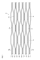
- FIG. 2 is a plan view of the optical fiber ribbon shown in FIG. 1.
- FIG. 3 is a graph showing the relationship between the tearing stress of the connecting portion and the torn length when the connecting portion of the optical fiber ribbon shown in FIG. 1 is torn.
- FIG. 4 is a graph showing the relationship between the tearing stress of the connecting portion and the length torn when the optical fiber ribbon according to the comparative example is torn.
- FIG. 5 is a schematic diagram illustrating a method for measuring tearing stress of a connecting portion.
- FIG. 6 is a sectional view showing an optical fiber ribbon according to the second embodiment.
- FIG. 7 is a plan view of the optical fiber ribbon shown in FIG. 6.
- FIG. 8 is a graph showing the relationship between the tearing stress of the connecting portion and the torn length when the connecting portion of the optical fiber ribbon shown in FIG. 6 is torn.
- FIG. 9 is a sectional view
- the connecting portion of the optical fiber tape If the strength of the connecting portion of the optical fiber tape is low, the connecting portion may be torn if a force such as bending is applied to the optical fiber tape or the cable on which the optical fiber tape is mounted. In this case, the individual optical fiber coated wires tend to fall apart, and the ease of handling the optical fiber tape coated wires sometimes deteriorates.
- the present disclosure provides an optical fiber ribbon that can suppress deterioration in handling properties.
- the optical fiber ribbon according to one aspect of the present disclosure includes: Comprising a plurality of optical fiber cores arranged in parallel in a direction perpendicular to the longitudinal direction, In at least a portion of the plurality of optical fibers, a plurality of connecting portions connecting adjacent optical fibers are provided intermittently in the longitudinal direction, One of the plurality of connection parts is configured such that tearing stress when torn in the longitudinal direction has a plurality of peaks, The tearing stress has a first peak indicating a maximum tearing stress, and a second peak indicating a tearing stress different from the maximum tearing stress, The tearing stress of the first peak is 0.01N or more, The tearing stress at the second peak is 50% or more of the tearing stress at the first peak.
- connection portion there are multiple peaks of stress that occur when the connection portion is torn. That is, even if a tearing force is applied to the connecting portion, the connecting portion will not be torn completely at once, but will be torn little by little. Therefore, the optical fiber coated wire is less likely to fall apart, and it is possible to suppress deterioration in the handling properties of the optical fiber tape coated wire.
- the first peak tearing stress which is the maximum tearing stress
- 0.01N 0.01N or more. Therefore, even if a slight force of less than 0.01 N is applied to the connecting portion, the connecting portion will not be torn. Therefore, it is possible to suppress deterioration in handling properties of the optical fiber ribbon.
- the second peak tearing stress is 50% or more of the first peak tearing stress. Even if a tear is formed in the joint against the tear stress of the first peak, the tear will not expand unless a relatively strong force of 50% or more of the tear stress of the first peak is applied. The wires are less likely to fall apart, and it is possible to suppress deterioration in the ease of handling the optical fiber ribbon.
- the elastic modulus of the one connecting portion may be 1 GPa or more and 5 GPa or less. According to the present disclosure, since the elastic modulus of the connecting portion is 1 GPa or more, it is possible to prevent the connecting portion from being destroyed by minute external forces. Furthermore, since the elastic modulus of the connecting portion is 5 GPa or less, transmission loss due to lateral pressure on the optical fiber ribbon at low temperatures can be reduced.
- the one connecting portion may have a tensile strength at break of 20 MPa or more. According to the present disclosure, since the tensile strength at break of the connecting portion is 20 MPa or more, the optical fiber coated wire is less likely to fall apart, and the handleability of the optical fiber tape coated wire is improved.
- the tearing stress at the first peak may be 0.03N or more. According to the present disclosure, since the first peak tearing stress is 0.03 N or more, it is possible to enhance the effect that the connecting portion is difficult to tear.
- the one connecting portion when a force corresponding to the first peak tearing stress acts on the one connecting portion, the one connecting portion is torn in the longitudinal direction.
- the first length of the connecting portion is the same as the second length of the one connecting portion that is torn in the longitudinal direction when a force corresponding to the second peak tearing stress is applied to the one connecting portion. It may be.
- the first length of the coupling part is torn in the longitudinal direction, and the coupling part corresponds to the second peak tearing stress.
- the length of the second length of the connecting portion torn in the longitudinal direction is the same, and the connecting portion is torn every predetermined length. That is, since the entire connecting portion is not torn at once, the optical fiber coated wire is less likely to fall apart, and it is possible to suppress a decrease in the handling properties of the optical fiber tape coated wire.
- FIG. 1 is a sectional view showing an optical fiber ribbon 1A according to the first embodiment.
- FIG. 2 is a plan view of the optical fiber ribbon 1A. Note that FIG. 1 is a cross-sectional view taken along line AA of the optical fiber ribbon 1A shown in FIG.
- optical fiber ribbon 1A As shown in FIGS. 1 and 2, in the optical fiber ribbon 1A, a plurality (12 in this example) of optical fibers 11 (11A to 11L in this example) are arranged in parallel in a direction orthogonal to the longitudinal direction. It is located in
- Each optical fiber core 11 has a glass fiber 12 consisting of, for example, a core and a cladding, and two coating layers 13 and 14 surrounding the glass fiber 12.
- the optical fiber core wire 11 may have a colored layer.
- the inner coating layer 13 of the two coating layers is formed of a cured product of primary resin.
- the outer coating layer 14 of the two coating layers is formed of a cured product of a secondary resin.
- a soft resin with a relatively low Young's modulus is used as a buffer layer for the primary resin constituting the inner coating layer 13 that contacts the glass fiber 12.
- a secondary resin constituting the outer coating layer 14 a hard resin having a relatively high Young's modulus is used as a protective layer.
- the Young's modulus of the cured product of the secondary resin is 900 MPa or more, preferably 1000 MPa or more, and more preferably 1500 MPa or more at room temperature (for example, 23° C.).
- the secondary resin that will constitute the outer coating layer 14 is preferably an ultraviolet curable resin composition containing a urethane acrylate oligomer, a monomer, and a photopolymerization initiator.
- the outer diameter R of the optical fiber core wire 11 is 180 ⁇ m or more and 250 ⁇ m or less. In the optical fiber ribbon 1A of this example, the outer diameter R is 200 ⁇ m.
- the number of fibers in the optical fiber tape 1A is 12, but the number is not limited to this.
- the number of fibers in the optical fiber tape 1A may be, for example, 24 fibers, 48 fibers, or the like.
- optical fibers 11A to 11L are alternately arranged in a state where they are separated from each other and in a state where they are in contact with each other.
- the optical fibers 11A to 11L of this example are arranged such that adjacent optical fibers are alternately placed at a certain distance and in contact with each other every two cores.
- the twelve optical fiber cores 11A to 11L arranged in parallel are all connected together by a connecting resin 21.
- a plurality of connecting portions 21a are provided intermittently in the longitudinal direction of the plurality of optical fiber cores 11.
- a plurality of uncoupled portions 23 are formed intermittently in the longitudinal direction of the plurality of optical fiber cores 11.
- the optical fiber tape coated wire 1A is an intermittently coupled optical fiber tape coated wire in which a coupled portion 21a and a non-coupled portion 23 are provided intermittently in the longitudinal direction for every two optical fiber coated wires. Note that the plan view of FIG. 2 shows a state in which the uncoupled portion 23 is opened in the parallel direction of the optical fiber cores 11.
- the connecting resin 21 of the optical fiber tape core 1A is provided so as to cover the outer periphery of each optical fiber core 11.
- the connecting resin 21 is provided with a plurality of connecting portions 21 a that connect adjacent optical fiber cores 11 in at least some of the plurality of optical fiber cores 11 .
- the connecting resin 21 is provided with an outer peripheral covering portion 21b that covers the outer periphery of each optical fiber core 11 (FIG. 1).
- the connecting portion 21a and the outer peripheral covering portion 21b are made of the same resin.
- the optical fiber ribbon 1A is provided with a plurality of unconnected portions 23 in which adjacent optical fibers are not connected.
- the connecting portion 21a is provided between the optical fibers 11D and 11E and between 11H and 11I.
- the uncoupled portion 23 is provided between the optical fiber cores 11B and 11C, between 11F and 11G, and between 11J and 11K.
- the adjacent optical fibers 11A and 11B, 11C and 11D, 11E and 11F, 11G and 11H, 11I and 11J, and 11K and 11L are arranged so that there is no gap between them. There is.
- the elastic modulus of the connecting resin 21 (the connecting portion 21a and the outer peripheral covering portion 21b) is 1 GPa or more and 5 GPa or less at room temperature (for example, 23° C.).
- the elastic modulus of the connecting portion 21a of this example is 2.5 GPa or more and 2.8 GPa or less.
- the elastic modulus of the connecting resin 21 can be measured as the elastic modulus in the thickness direction of the adhesive resin after curing using a nanoindenter (HYSITRON TI950 Tribolndenter manufactured by BRUKER) by a test method based on ISO 14577. In this example, the indentation depth was 100 nm, and the elastic modulus of the connecting resin 21 was measured using a Berkovich indenter.
- the Young's modulus of the connecting portion 21a is, for example, 868 MPa at room temperature (for example, 23° C.). Further, the tensile breaking strength of the connecting portion 21a is 20 MPa or more. The tensile strength at break of the connecting portion 21a of this example is, for example, 33 MPa, and the elongation at break is 39%.
- the connecting resin 21 is, for example, an ultraviolet curable resin, a thermosetting resin, or the like.
- the adhesion between the outermost layer of the optical fiber core 11 and the connecting resin 21 is large.
- the connecting resin 21 may contain a ketone solvent. This increases the adhesion force with the outermost layer of the optical fiber core 11. This makes it difficult for the connecting resin 21 to separate from the optical fiber coated wire 11, and for the optical fiber coated wire 11 to become less likely to fall apart.
- An example of an index of the adhesion force is the tearing stress required to separate the connecting resin 21 from the outer circumferential surface of the optical fiber core 11.
- the tearing stress of the connecting portion 21a is measured as follows. A cut is made with a knife or a razor in the connecting portion 21a formed at the center of one end of the optical fiber tape core 1A in the width direction (parallel direction of the optical fiber cores 11), and a 12-core optical fiber tape core is formed. Cut the end of wire 1A into 6 cores each. Each end of the separated six-core outer peripheral covering portion 21b is grasped and pulled at a speed of 200 mm/min in a direction orthogonal to the longitudinal direction and the width direction, and the tensile force at that time is measured as tearing stress.
- FIG. 3 is a graph showing the relationship between the tearing stress of the connecting portion 21a and the torn length when one connecting portion 21a of the optical fiber ribbon core 1A is torn.
- the connecting portion 21a of this example is configured such that tearing stress has a plurality of peaks when it is torn in the longitudinal direction. In other words, when a force equivalent to tearing stress is applied to the connecting portion 21a, the connecting portion 21a is not completely torn by one force, but is torn little by little through multiple peaks.
- the tearing stress of the connecting portion 21a has a first peak PA1 indicating the maximum tearing stress and a second peak PA2 indicating a tearing stress different from the maximum tearing stress.
- the tearing stress of the first peak PA1, which is the maximum tearing stress is 0.01N or more.
- the tearing stress of the second peak PA2 is 50% or more of the tearing stress of the first peak PA1.
- the tearing stress of the connecting portion 21a further has a third peak PA3, a fourth peak PA4, and a fifth peak PA5, which are different from the tearing stress of the first peak PA1 and the second peak PA2.
- the second peak PA2, the third peak PA3, the fourth peak PA4, and the fifth peak PA5 are examples of second peaks that are 50% or more of the tearing stress of the first peak.
- the length of the connecting portion 21a torn at this time is defined as a fifth length LA5.
- the connecting portion 21a is further torn in the longitudinal direction.
- the length of the connecting portion 21a torn at this time is defined as a fourth length LA4.
- the connecting part 21a is torn by a third length LA3, and when a force corresponding to the tearing stress of the second peak PA2 is applied, the connecting part 21a is torn by a third length LA3.
- the connecting portion 21a is torn by two lengths LA2, and when a force corresponding to the tearing stress of the first peak PA1 is applied, the connecting portion 21a is torn by a first length LA1.
- the tearing stress of the fifth peak PA5 is, for example, 0.016 N, and the fifth length LA5 is torn by, for example, about 13 mm.
- the tearing stress at the fourth peak PA4 is, for example, 0.016N, and the fourth length LA4 is torn by, for example, about 13 mm.
- the tearing stress at the third peak PA3 is, for example, 0.016N, and the third length LA3 is torn by, for example, about 10 mm.
- the tearing stress at the second peak PA2 is, for example, 0.016N, and the second length LA2 is torn by, for example, about 10 mm.
- the tearing stress of the first peak PA1 is, for example, 0.018N, and the first length LA1 is, for example, about 10 mm.
- the tearing stress of the second peak PA2 is the same as the tearing stress of the first peak PA1 (90% of the tearing stress of the first peak PA1).
- the first length LA1, the second length LA2, the third length LA3, the fourth length LA4, or the fifth length LA5 are the same. Note that in this example, "the same length” does not mean that the two lengths completely match, but rather that the length of one is within ⁇ 30% of the length of the other.
- the length of the connecting portion 21a that is torn may vary depending on the adhesion between the optical fiber core 11 and the connecting portion 21a (the connecting resin 21) in addition to the tearing stress.
- the connecting portion 21a breaks, and a tear may be formed between adjacent optical fiber cores.
- the connecting resin 21 forming the connecting portion 21a is peeled off from the optical fiber coated wire 11, a tear may be formed between adjacent optical fiber coated wires.
- FIG. 4 is a graph showing the relationship between the tearing stress of the connecting portion 21a and the torn length when the connecting portion 21a of the optical fiber ribbon core 1Z as a comparative example is torn.
- the elastic modulus of the connecting resin 21 (the connecting portion 21a and the outer circumferential coating portion 21b) of the optical fiber tape core wire 1Z is 1.5 GPa at room temperature (for example, 23° C.).
- the Young's modulus of the connecting portion 21a is 115 MPa at room temperature (for example, 23° C.)
- the tensile strength at break of the connecting portion 21a is, for example, 16 MPa
- the elongation at break of the connecting portion 21a is It is 38%.
- the peeling strength of the optical fiber tape core 1A according to the first embodiment is set as 1, the peeling strength of the optical fiber tape core 1Z according to the comparative example is 0.2 or more and 0.3 or less. Except for the differences in the physical properties of the connecting resin 21, the configuration of the optical fiber ribbon 1Z is the same as the configuration of the optical fiber ribbon 1A, so the description thereof will be omitted.
- the connecting portion 21a of the optical fiber tape core wire 1Z according to the comparative example is configured such that the tearing stress has multiple peaks when it is torn in the longitudinal direction.
- the tearing stress at the second peak PZ2 is different from the optical fiber ribbon 1A according to the present example in that the tearing stress at the second peak PZ2 is not 50% or more of the tearing stress at the first peak PZ1.
- the tearing stress at the first peak PZ1 is, for example, 0.02N
- the tearing stress at the second peak PZ2 is, for example, 0.009N. That is, the tearing stress at the second peak PZ2 is about 45% of the tearing stress at the first peak PZ1.
- the tearing stress at the third peak PZ3 and the tearing stress at the fourth peak PZ4 are both about 0.005N, which is about 25% of the tearing stress at the first peak PZ1.
- a force corresponding to the tearing stress of the first peak PZ1 acts on the connecting portion 21a, and a tear of the first length LZ1 is formed.
- the first length LZ1 is, for example, 20 mm.
- the tearing stress of the fourth peak PZ4, the third peak PZ3, and the second peak PZ2 that is, the tearing stress of the first peak PZ1 is less than 50%. If a weak force acts on the connecting portion 21a, this tear will expand. If the tear is enlarged by a relatively weak force, the optical fiber coated wire 11 tends to fall apart, and the handling of the optical fiber tape coated wire 1Z may deteriorate.
- the tearing stress of the first peak PA1 which is the maximum tearing stress
- the connecting portion 21a Even if the force is applied, the connecting portion 21a will not be torn.
- the tearing stress of the second peak PA2 is 50% or more of the tearing stress of the first peak PA1
- a relatively large tearing force is applied to the connecting portion 21a, and a tear is formed in a part of the connecting portion 21a. Even if it is, the tear in the connecting portion 21a will not expand unless a relatively large tearing force is applied again. For this reason, the optical fiber coated wire 11 is less likely to fall apart, and the optical fiber tape coated wire 1A is easy to handle, making it easier to fusion splice the optical fiber tape coated wire 1A all at once.
- the elastic modulus of the connecting portion 21a in this example is 1 GPa or more. For this reason, it is possible to prevent the connecting portion 21a from being destroyed by minute external forces. Further, the elastic modulus of the connecting portion 21a is 5 GPa or less. Therefore, transmission loss due to lateral pressure on the optical fiber ribbon 1A at low temperatures can be reduced.
- the tensile breaking strength of the connecting portion 21a of this example is 20 MPa or more. Since the connecting portion 21a is not broken by a minute force, the optical fiber coated wire 11 is less likely to fall apart, and the handling of the optical fiber tape coated wire 1A is improved.
- the connecting portion 21a of the optical fiber tape core 1A is torn into arbitrary lengths. That is, since the entire connecting portion 21a is not torn at once, the optical fiber coated wire 11 is less likely to fall apart, and it is possible to suppress a decrease in the ease of handling of the optical fiber tape coated wire 1A.
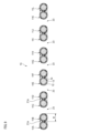
- FIG. 5 is a schematic diagram showing a method for measuring tearing stress of the connecting portion 21a.
- the outer periphery coating portions 21b of the six optical fibers 11A to 11F of the optical fiber ribbon 1A are held by the first gripping portion G1, and the six optical fibers 11G are held by the first gripping portion G1.
- the outer peripheral covering portion 21b of 11L is gripped by the second gripping portion G2.
- the first gripping part G1 is arranged above the optical fiber ribbon 1A
- the second gripping part G2 is arranged below the optical fiber ribbon 1A.
- a connecting portion 21a is formed between the optical fiber coated wire 11F and the optical fiber coated wire 11G.
- the length La of the connecting portion 21a in the longitudinal direction is about 40 mm to 90 mm.
- the position of one end of the connecting part 21a is the position where the optical fiber coated wire 11F starts to be bent upward by the first gripping part G1, and the optical fiber coated wire 11G is bent in the direction by the second gripping part G2.
- the first gripping part G1 and the second gripping part G2 are arranged so as to be separated from each other in the vertical direction so as to reach the position where the bending starts.
- the connecting portion 21a connects the optical fiber coated wire 11F and the optical fiber coated wire 11G over the entire length.
- the initial distance D between the first grip part G1 and the second grip part G2 in the vertical direction is 70 mm.
- the length of the optical fiber ribbon 1A to be measured in the longitudinal direction is 150 mm.
- the second gripping part G2 is fixed, and the first gripping part G1 is moved upward away from the second gripping part G2.
- the moving speed of the first gripping part G1 is 200 mm/min.
- the optical fiber coated wire 11F held by the first gripping part G1 separates from the optical fiber coated wire 11G held by the second gripping part G2.
- the connecting portion 21a connecting the optical fiber coated wire 11F and the optical fiber coated wire 11G begins to be torn.
- a detector installed directly or indirectly on the first gripping part G1 measures the force applied to the first gripping part G1 when the connecting part 21a is torn as the tearing stress of the connecting part 21a. do.
- the length of the torn connecting portion 21a is measured.
- the second gripping part G2 is fixed and the first gripping part G1 is moved, but the first gripping part G1 may be fixed and the second gripping part G2 is moved.
- FIG. 6 shows a cross-sectional view of the optical fiber ribbon 1B.
- the optical fiber ribbon 1B differs from the first embodiment in that adjacent optical fibers are arranged alternately between a state with a certain distance between them and a state where they are connected to each other. This is different from the optical fiber ribbon 1A.
- the connecting portion 21a is between the optical fibers 11A and 11B, between 11C and 11D, between 11E and 11F, between 11G and 11H, and between 11I and 11B. 11J, and between 11K and 11L.
- the uncoupled portions 23 are provided between the optical fibers 11B and 11C, between 11D and 11E, between 11F and 11G, between 11H and 11I, and between 11J and 11K.
- the elastic modulus of the connecting portion 21a in this example is, for example, 2.6 GPa.
- FIG. 7 is a plan view of the optical fiber ribbon 1B.
- a plurality of connecting portions 21a are provided intermittently in the longitudinal direction of the plurality of coated optical fibers 11.
- a plurality of non-coupled portions 23 are also formed intermittently in the longitudinal direction of the plurality of coated optical fibers 11.
- the optical fiber tape coated wire 1B is an intermittently coupled optical fiber tape coated wire in which coupling portions 21a and non-coupled portions 23 are provided intermittently in the longitudinal direction for each optical fiber coated wire.
- the other configurations are the same as the optical fiber tape core 1A. Note that the plan view of FIG. 7 shows a state in which the uncoupled portion 23 is opened in the parallel direction of the optical fiber cores 11.
- FIG. 6 is a BB sectional view of the optical fiber ribbon 1B shown in FIG.
- FIG. 8 is a graph showing the relationship between the tearing stress of the connecting portion 21a and the torn length when the connecting portion 21a of the optical fiber ribbon core 1B is torn.
- the connecting portion 21a of this example is also configured so that the tearing stress has a plurality of peaks when it is torn in the longitudinal direction.
- the tearing stress of the connecting portion 21a has a first peak PB1 indicating the maximum tearing stress and a second peak PB2 indicating a tearing stress different from the maximum tearing stress.
- the first peak PB1 has two peaks PB11 and PB12, they are regarded as one peak here. More specifically, if the tearing stress of the second peak PB12 located close to the first peak PB11 is within ⁇ 20% of the tearing stress of the first peak PB11, the two peaks PB11 and PB12 are the same.
- the tearing stress of the first peak PB1 is regarded as the tearing stress of the first peak PB1.
- the tearing stress of the first peak PB1 which is the maximum tearing stress, is 0.03N or more.
- the tearing stress of the first peak PB1 in this example is, for example, 0.062N.
- the tearing stress of the second peak PB2 is 50% or more of the tearing stress of the first peak PB1.
- the tearing stress of the second peak PB2 in this example is, for example, 0.051 N, which is 83% of the tearing stress of the first peak PB1.
- the tearing stress of the first peak PB1 is 0.03 N or more, so the effect of making the connecting portion 21a difficult to tear can be enhanced.
- optical fiber ribbons 1A and 1B were provided with the connecting resin 21 covering the outer periphery of each of the optical fibers 11, it is not necessarily necessary to include the connecting resin 21 covering the outer periphery.
- FIG. 9 an optical fiber ribbon core 1C according to a modified example will be described.
- symbol is attached
- FIG. 9 shows a cross-sectional view of the optical fiber ribbon 1C.
- Optical fiber tape core 1C is an optical fiber tape core in that adjacent optical fiber cores are arranged alternately between a state with a certain distance between them and a state where they are connected to each other. It is different from 1A. Furthermore, the optical fiber tape core 1C differs from the optical fiber tape cores 1A and 1B in that it does not have an outer peripheral coating portion 21b that covers the outer periphery of each optical fiber core 11. Some adjacent optical fibers are connected to each other by a connecting portion 21a.
- the connecting portion 21a is between the optical fibers 11A and 11B, between 11C and 11D, between 11E and 11F, between 11G and 11H, and between 11I and 11C. 11J, and between 11K and 11L.
- the connecting portion 21a is formed so that there is no gap between these two adjacent optical fibers.
- the non-coupling portion 23 is provided between the optical fiber cores 11B and 11C, between 11D and 11E, between 11F and 11G, between 11H and 11I, and between 11J and 11K. .
- Such an optical fiber tape core 1C has the same effects as the optical fiber tape cores 1A and 1B.
- the connecting portion 21a of the optical fiber ribbon 1C is also configured so that the tearing stress has multiple peaks when it is torn in the longitudinal direction, and the optical fiber ribbon 1C has a reduced handling property. can be suppressed.
- the connecting portion 21a and the non-connecting portion 23 are formed by providing the connecting resin 21 in a portion in the longitudinal direction, but the forming method is not limited to this.
- the uncoupled portion 23 may be formed by providing a tape coating that integrally covers each optical fiber core 11 and cutting a portion of the length between the optical fiber cores 11 .
- 1A, 1B, 1C, 1Z Optical fiber tape 11, 11A, 11B, 11C, 11D, 11E, 11F, 11G, 11H, 11I, 11J, 11K, 11L: Optical fiber 12: Glass fiber 13: Inside Coating layer 14: Outer coating layer 21: Connecting resin 21a: Connecting portion 21b: Outer periphery coating portion 23: Unconnected portion D: Initial distance LA1, LZ1: First length LA2: Second length LA3: Third length LA4: Fourth length LA5: Fifth length PA1, PB1, PZ1: First peak PA2, PB2, PZ2: Second peak PA3: Third peak PA4: Fourth peak PA5: Fifth peak PB11, PB12: Peak R: outer diameter
Landscapes
- Physics & Mathematics (AREA)
- General Physics & Mathematics (AREA)
- Optics & Photonics (AREA)
- Engineering & Computer Science (AREA)
- Manufacturing & Machinery (AREA)
- Mechanical Coupling Of Light Guides (AREA)
- Optical Fibers, Optical Fiber Cores, And Optical Fiber Bundles (AREA)
Priority Applications (4)
| Application Number | Priority Date | Filing Date | Title |
|---|---|---|---|
| CN202380039836.XA CN119173797A (zh) | 2022-05-11 | 2023-05-10 | 光纤带芯线 |
| US18/864,196 US20250298206A1 (en) | 2022-05-11 | 2023-05-10 | Optical fiber ribbon |
| JP2024520473A JPWO2023219105A1 (https=) | 2022-05-11 | 2023-05-10 | |
| EP23803580.2A EP4524630A4 (en) | 2022-05-11 | 2023-05-10 | FIBER OPTIC RIBBON |
Applications Claiming Priority (2)
| Application Number | Priority Date | Filing Date | Title |
|---|---|---|---|
| JP2022078228 | 2022-05-11 | ||
| JP2022-078228 | 2022-05-11 |
Publications (1)
| Publication Number | Publication Date |
|---|---|
| WO2023219105A1 true WO2023219105A1 (ja) | 2023-11-16 |
Family
ID=88730333
Family Applications (1)
| Application Number | Title | Priority Date | Filing Date |
|---|---|---|---|
| PCT/JP2023/017572 Ceased WO2023219105A1 (ja) | 2022-05-11 | 2023-05-10 | 光ファイバテープ心線 |
Country Status (5)
| Country | Link |
|---|---|
| US (1) | US20250298206A1 (https=) |
| EP (1) | EP4524630A4 (https=) |
| JP (1) | JPWO2023219105A1 (https=) |
| CN (1) | CN119173797A (https=) |
| WO (1) | WO2023219105A1 (https=) |
Citations (10)
| Publication number | Priority date | Publication date | Assignee | Title |
|---|---|---|---|---|
| JP2002328283A (ja) * | 2001-04-27 | 2002-11-15 | Mitsubishi Cable Ind Ltd | 分割型光ファイバテープ |
| JP2013182157A (ja) | 2012-03-02 | 2013-09-12 | Fujikura Ltd | 光ファイバテープ心線及びその光ファイバテープ心線を収納した光ファイバケーブル |
| JP6106253B1 (ja) * | 2015-12-04 | 2017-03-29 | 株式会社フジクラ | 光ファイバテープ、光ファイバテープの製造方法、及び間欠固定型光ファイバテープの連結部の形成に用いられる紫外線硬化樹脂組成物 |
| JP2017062431A (ja) * | 2015-09-25 | 2017-03-30 | 住友電気工業株式会社 | 光ファイバテープ心線 |
| WO2017175414A1 (ja) * | 2016-04-08 | 2017-10-12 | 株式会社フジクラ | 光ファイバテープの製造方法、光ファイバテープ及び光ケーブル |
| JP2019168553A (ja) | 2018-03-22 | 2019-10-03 | 株式会社フジクラ | 光ファイバテープ心線 |
| WO2020162501A1 (ja) * | 2019-02-06 | 2020-08-13 | 住友電気工業株式会社 | 間欠連結型光ファイバテープ心線、光ファイバケーブルおよび間欠連結型光ファイバテープ心線の製造方法 |
| US20200271879A1 (en) * | 2017-07-11 | 2020-08-27 | Prysmian S.P.A. | An Optical Fiber Ribbon and a Method of Producing the Same |
| WO2022025116A1 (ja) * | 2020-07-29 | 2022-02-03 | 住友電気工業株式会社 | 間欠連結型光ファイバテープ心線の製造方法及び間欠連結型光ファイバテープ心線 |
| JP2022078228A (ja) | 2016-10-18 | 2022-05-24 | マウェタール エルエルシー | 環境に優しい船舶用燃料 |
Family Cites Families (1)
| Publication number | Priority date | Publication date | Assignee | Title |
|---|---|---|---|---|
| JP7084449B2 (ja) * | 2020-07-10 | 2022-06-14 | 古河電気工業株式会社 | 光ファイバテープ心線、光ファイバケーブル |
-
2023
- 2023-05-10 CN CN202380039836.XA patent/CN119173797A/zh active Pending
- 2023-05-10 JP JP2024520473A patent/JPWO2023219105A1/ja active Pending
- 2023-05-10 WO PCT/JP2023/017572 patent/WO2023219105A1/ja not_active Ceased
- 2023-05-10 US US18/864,196 patent/US20250298206A1/en active Pending
- 2023-05-10 EP EP23803580.2A patent/EP4524630A4/en active Pending
Patent Citations (10)
| Publication number | Priority date | Publication date | Assignee | Title |
|---|---|---|---|---|
| JP2002328283A (ja) * | 2001-04-27 | 2002-11-15 | Mitsubishi Cable Ind Ltd | 分割型光ファイバテープ |
| JP2013182157A (ja) | 2012-03-02 | 2013-09-12 | Fujikura Ltd | 光ファイバテープ心線及びその光ファイバテープ心線を収納した光ファイバケーブル |
| JP2017062431A (ja) * | 2015-09-25 | 2017-03-30 | 住友電気工業株式会社 | 光ファイバテープ心線 |
| JP6106253B1 (ja) * | 2015-12-04 | 2017-03-29 | 株式会社フジクラ | 光ファイバテープ、光ファイバテープの製造方法、及び間欠固定型光ファイバテープの連結部の形成に用いられる紫外線硬化樹脂組成物 |
| WO2017175414A1 (ja) * | 2016-04-08 | 2017-10-12 | 株式会社フジクラ | 光ファイバテープの製造方法、光ファイバテープ及び光ケーブル |
| JP2022078228A (ja) | 2016-10-18 | 2022-05-24 | マウェタール エルエルシー | 環境に優しい船舶用燃料 |
| US20200271879A1 (en) * | 2017-07-11 | 2020-08-27 | Prysmian S.P.A. | An Optical Fiber Ribbon and a Method of Producing the Same |
| JP2019168553A (ja) | 2018-03-22 | 2019-10-03 | 株式会社フジクラ | 光ファイバテープ心線 |
| WO2020162501A1 (ja) * | 2019-02-06 | 2020-08-13 | 住友電気工業株式会社 | 間欠連結型光ファイバテープ心線、光ファイバケーブルおよび間欠連結型光ファイバテープ心線の製造方法 |
| WO2022025116A1 (ja) * | 2020-07-29 | 2022-02-03 | 住友電気工業株式会社 | 間欠連結型光ファイバテープ心線の製造方法及び間欠連結型光ファイバテープ心線 |
Non-Patent Citations (1)
| Title |
|---|
| See also references of EP4524630A4 |
Also Published As
| Publication number | Publication date |
|---|---|
| CN119173797A (zh) | 2024-12-20 |
| US20250298206A1 (en) | 2025-09-25 |
| JPWO2023219105A1 (https=) | 2023-11-16 |
| EP4524630A4 (en) | 2025-09-10 |
| EP4524630A1 (en) | 2025-03-19 |
Similar Documents
| Publication | Publication Date | Title |
|---|---|---|
| US10007078B2 (en) | Optical fiber ribbon | |
| JP4049154B2 (ja) | 光ファイバテープ心線 | |
| CN100365458C (zh) | 具有优先撕裂部分的可剥离缓冲层及其制造方法 | |
| CN100430767C (zh) | 具有优先分离顺序的光纤带 | |
| TW420757B (en) | Divided type optical fiber tape core wires | |
| CN113316733B (zh) | 间歇连结型光纤带芯线、光纤线缆及间歇连结型光纤带芯线的制造方法 | |
| AU777514B2 (en) | Coated optical fiber | |
| JP6273847B2 (ja) | 光ファイバおよび光ケーブル | |
| CN1260592C (zh) | 容易接近剥离索及具有剥离索可靠性的纤维光缆 | |
| JP2004206048A (ja) | 光ファイバテープ心線及びその製造方法 | |
| JP3902201B2 (ja) | 光ファイバ素線及び光ファイバテープ心線 | |
| CN113892049B (zh) | 光纤带状芯线、光缆及光纤带状芯线的制造方法 | |
| JP2015132647A (ja) | 光ケーブル | |
| WO2023219105A1 (ja) | 光ファイバテープ心線 | |
| JP7816160B2 (ja) | 光ファイバテープ心線 | |
| US20230393350A1 (en) | Optical fiber ribbon and method for manufacturing optical fiber ribbon | |
| JP2005037936A (ja) | 光ファイバケーブル | |
| JP2000231042A (ja) | 分割型光ファイバテープ心線 | |
| WO2022131099A1 (ja) | 光ファイバテープ心線 | |
| JP3067763B1 (ja) | 分割型光ファイバテ―プ心線 | |
| JPH02289804A (ja) | 光フアイバユニット | |
| JP2004117854A (ja) | 光ファイバケーブル | |
| WO2023210461A1 (ja) | 光ファイバ素線、および光ファイバリボンの製造方法 | |
| JP2007272099A (ja) | 光ファイバテープおよび光ケーブル | |
| JP2006208940A (ja) | 光ファイバテープおよび光ケーブル |
Legal Events
| Date | Code | Title | Description |
|---|---|---|---|
| 121 | Ep: the epo has been informed by wipo that ep was designated in this application |
Ref document number: 23803580 Country of ref document: EP Kind code of ref document: A1 |
|
| WWE | Wipo information: entry into national phase |
Ref document number: 2024520473 Country of ref document: JP |
|
| WWE | Wipo information: entry into national phase |
Ref document number: 18864196 Country of ref document: US |
|
| WWE | Wipo information: entry into national phase |
Ref document number: 2023803580 Country of ref document: EP |
|
| NENP | Non-entry into the national phase |
Ref country code: DE |
|
| ENP | Entry into the national phase |
Ref document number: 2023803580 Country of ref document: EP Effective date: 20241211 |
|
| WWP | Wipo information: published in national office |
Ref document number: 18864196 Country of ref document: US |