WO2023218884A1 - 撮像装置、制御方法、プログラム - Google Patents
撮像装置、制御方法、プログラム Download PDFInfo
- Publication number
- WO2023218884A1 WO2023218884A1 PCT/JP2023/015646 JP2023015646W WO2023218884A1 WO 2023218884 A1 WO2023218884 A1 WO 2023218884A1 JP 2023015646 W JP2023015646 W JP 2023015646W WO 2023218884 A1 WO2023218884 A1 WO 2023218884A1
- Authority
- WO
- WIPO (PCT)
- Prior art keywords
- still image
- vibration
- imaging
- exposure
- notification
- Prior art date
- Legal status (The legal status is an assumption and is not a legal conclusion. Google has not performed a legal analysis and makes no representation as to the accuracy of the status listed.)
- Ceased
Links
Images







Classifications
-
- H—ELECTRICITY
- H04—ELECTRIC COMMUNICATION TECHNIQUE
- H04N—PICTORIAL COMMUNICATION, e.g. TELEVISION
- H04N23/00—Cameras or camera modules comprising electronic image sensors; Control thereof
- H04N23/60—Control of cameras or camera modules
- H04N23/63—Control of cameras or camera modules by using electronic viewfinders
- H04N23/633—Control of cameras or camera modules by using electronic viewfinders for displaying additional information relating to control or operation of the camera
- H04N23/635—Region indicators; Field of view indicators
-
- G—PHYSICS
- G03—PHOTOGRAPHY; CINEMATOGRAPHY; ANALOGOUS TECHNIQUES USING WAVES OTHER THAN OPTICAL WAVES; ELECTROGRAPHY; HOLOGRAPHY
- G03B—APPARATUS OR ARRANGEMENTS FOR TAKING PHOTOGRAPHS OR FOR PROJECTING OR VIEWING THEM; APPARATUS OR ARRANGEMENTS EMPLOYING ANALOGOUS TECHNIQUES USING WAVES OTHER THAN OPTICAL WAVES; ACCESSORIES THEREFOR
- G03B17/00—Details of cameras or camera bodies; Accessories therefor
- G03B17/02—Bodies
- G03B17/12—Bodies with means for supporting objectives, supplementary lenses, filters, masks, or turrets
- G03B17/14—Bodies with means for supporting objectives, supplementary lenses, filters, masks, or turrets interchangeably
-
- G—PHYSICS
- G03—PHOTOGRAPHY; CINEMATOGRAPHY; ANALOGOUS TECHNIQUES USING WAVES OTHER THAN OPTICAL WAVES; ELECTROGRAPHY; HOLOGRAPHY
- G03B—APPARATUS OR ARRANGEMENTS FOR TAKING PHOTOGRAPHS OR FOR PROJECTING OR VIEWING THEM; APPARATUS OR ARRANGEMENTS EMPLOYING ANALOGOUS TECHNIQUES USING WAVES OTHER THAN OPTICAL WAVES; ACCESSORIES THEREFOR
- G03B17/00—Details of cameras or camera bodies; Accessories therefor
- G03B17/18—Signals indicating condition of a camera member or suitability of light
-
- H—ELECTRICITY
- H04—ELECTRIC COMMUNICATION TECHNIQUE
- H04N—PICTORIAL COMMUNICATION, e.g. TELEVISION
- H04N23/00—Cameras or camera modules comprising electronic image sensors; Control thereof
- H04N23/40—Circuit details for pick-up tubes
-
- H—ELECTRICITY
- H04—ELECTRIC COMMUNICATION TECHNIQUE
- H04N—PICTORIAL COMMUNICATION, e.g. TELEVISION
- H04N23/00—Cameras or camera modules comprising electronic image sensors; Control thereof
- H04N23/60—Control of cameras or camera modules
-
- H—ELECTRICITY
- H04—ELECTRIC COMMUNICATION TECHNIQUE
- H04N—PICTORIAL COMMUNICATION, e.g. TELEVISION
- H04N23/00—Cameras or camera modules comprising electronic image sensors; Control thereof
- H04N23/60—Control of cameras or camera modules
- H04N23/667—Camera operation mode switching, e.g. between still and video, sport and normal or high- and low-resolution modes
-
- H—ELECTRICITY
- H04—ELECTRIC COMMUNICATION TECHNIQUE
- H04N—PICTORIAL COMMUNICATION, e.g. TELEVISION
- H04N23/00—Cameras or camera modules comprising electronic image sensors; Control thereof
- H04N23/60—Control of cameras or camera modules
- H04N23/68—Control of cameras or camera modules for stable pick-up of the scene, e.g. compensating for camera body vibrations
- H04N23/681—Motion detection
- H04N23/6812—Motion detection based on additional sensors, e.g. acceleration sensors
-
- H—ELECTRICITY
- H04—ELECTRIC COMMUNICATION TECHNIQUE
- H04N—PICTORIAL COMMUNICATION, e.g. TELEVISION
- H04N23/00—Cameras or camera modules comprising electronic image sensors; Control thereof
- H04N23/60—Control of cameras or camera modules
- H04N23/68—Control of cameras or camera modules for stable pick-up of the scene, e.g. compensating for camera body vibrations
- H04N23/682—Vibration or motion blur correction
- H04N23/685—Vibration or motion blur correction performed by mechanical compensation
- H04N23/687—Vibration or motion blur correction performed by mechanical compensation by shifting the lens or sensor position
-
- H—ELECTRICITY
- H04—ELECTRIC COMMUNICATION TECHNIQUE
- H04N—PICTORIAL COMMUNICATION, e.g. TELEVISION
- H04N23/00—Cameras or camera modules comprising electronic image sensors; Control thereof
- H04N23/70—Circuitry for compensating brightness variation in the scene
- H04N23/73—Circuitry for compensating brightness variation in the scene by influencing the exposure time
Definitions
- the present technology relates to an imaging device, a control method, and a program, and relates to a technical field related to, for example, operation notification processing.
- Some imaging devices such as digital cameras, provide notification through vibration or sound, for example, when a user operates a shutter. The user can be informed by vibrations and sounds that the shutter operation has been accepted and a still image has been captured.
- Patent Document 1 listed below describes an imaging device that uses vibration to notify the timing of the end of imaging.
- a through image is displayed on a display panel or a viewfinder provided on the main body.
- the user usually measures the shutter operation timing while looking at the through image. Even in the case of continuous shooting, by continuously displaying the through image, the user can accurately check the subject even during continuous shooting (for example, while continuously pressing the shutter button).
- the user in response to a shutter operation, the user is notified by vibration or sound, for example, so that the user can recognize that the operation has been accepted and a still image has been recorded, and the through image shows what kind of image has been recorded. You can know just how much.
- notification is provided by vibration, if the vibration is made during the exposure period immediately after the shutter operation, there is a possibility that the recorded still image will be blurred. We also want to make it easier for the user to understand when a still image was recorded, not just in the form of vibration or sound notifications.
- this technology proposes a technology that provides notifications using vibrations, etc., at more appropriate timing.
- An imaging device includes an image sensor section that exposes incident light and outputs a captured image signal, a notification section, and a still image that is captured by the image sensor section to generate a still image in response to a still image capturing instruction.
- a control unit that performs control to cause the notification unit to execute a notification corresponding to the imaging exposure in a period different from an exposure period of the still image imaging exposure.
- the still image capturing instruction is, for example, a user's shutter operation or an automatic shutter timing trigger.
- Still image imaging exposure is exposure to obtain captured image data to be recorded or transmitted as a still image, for example, in response to a still image imaging instruction, and exposure to obtain an image signal that is not recorded or transmitted as a still image. except.
- exposure only for through image display or analysis is excluded.
- the user can feel that the shutter has been pressed by notifying the user by vibrating the housing of the imaging device in response to the user's shutter operation. notifications do not overlap with the exposure period.
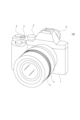
- FIG. 1 is a perspective view of an imaging device according to an embodiment of the present technology.
- FIG. 2 is a rear view of the imaging device according to the embodiment.
- FIG. 1 is a block diagram of an internal configuration of an imaging device according to an embodiment. It is an explanatory diagram of vibration timing of an embodiment.
- FIG. 3 is an explanatory diagram of the relationship between vibration timing and display according to the embodiment.
- FIG. 6 is an explanatory diagram of vibration timing control during continuous shooting according to the embodiment.
- FIG. 3 is an explanatory diagram of exposure timing control during continuous shooting according to the embodiment.
- FIG. 3 is an explanatory diagram of vibration control during long exposure according to the embodiment.
- FIG. 6 is an explanatory diagram of presentation of determination results of vibration and imaging conditions according to the embodiment.
- FIG. 6 is an explanatory diagram of an example of presenting a determination result of an imaging situation according to the embodiment.
- FIG. 6 is an explanatory diagram of the presentation timing of the determination result of the imaging situation according to the embodiment.
- FIG. 6 is an explanatory diagram of the presentation timing of the determination result of the imaging situation according to the embodiment.
- FIG. 6 is an explanatory diagram of an example of presenting a determination result of an imaging situation according to the embodiment.
- FIG. 7 is an explanatory diagram of an example of stepwise presentation of the determination result of the imaging situation according to the embodiment.
- FIG. 7 is an explanatory diagram of an example of stepwise presentation of the determination result of the imaging situation according to the embodiment. It is a flowchart of the 1st example of notification control processing of an embodiment.
- Configuration of imaging device The configuration of the imaging device 100 will be described with reference to FIGS. 1, 2, and 3. Note that in this disclosure, the term “image” is used to include both “still images” and “videos.” When specifically distinguishing between them, they are written as “still images” and “videos.”
- FIG. 1 shows a front perspective view of the imaging device 100
- FIG. 2 shows a rear view.
- the imaging device 100 is a so-called digital still camera, and can perform both still image imaging and video imaging by switching the imaging mode.
- the imaging device 100 is not limited to a digital still camera, but may be a video camera mainly used for video imaging, a camera that can only take still images, or a camera that can only take video images. It may be. Of course, it may also be a professional camera used at a broadcasting station or the like.
- a lens barrel 2 is arranged on the front side of a main body housing 1 that constitutes a camera main body.
- the lens barrel 2 is removably attached to the main body housing 1, allowing lenses to be replaced.
- the lens barrel 2 cannot be attached to or detached from the main body housing 1.
- a display panel 4 is provided using a display device such as a liquid crystal display (LCD) or an organic EL (electro-luminescence) display. It will be done.
- a display section formed using an LCD, an organic EL display, or the like is also provided.
- the viewfinder 5 is, for example, an electronic view finder (EVF). However, an optical view finder (OVF) or a hybrid view finder (HVF) using a transmissive liquid crystal may be used.
- the imaging device 100 is provided with both the display panel 4 and the viewfinder 5, but the present invention is not limited to this, and a configuration in which only one of the display panel 4 and the viewfinder 5 is provided,
- the display panel 4 and/or the viewfinder 5 may be configured to be removable.
- Various operators 3 are provided on the main body casing 1 and the lens barrel 2 of the imaging device 100.
- various types of operators 3 such as keys, dials, rings, and combination press/rotate operators, are provided to realize various operating functions.
- shutter operations, menu operations, playback operations, mode selection operations, focus operations, zoom operations, and parameter selection operations such as shutter speed and F-number are possible.
- FIG. 3 shows the internal configuration of the imaging device 100 including the lens barrel 2. Note that FIG. 3 shows an example in which the imaging device 100 is configured by being divided into a main body housing 1 and a lens barrel 2. Although there is a configuration in which the lens barrel 2 cannot be attached or detached from the main body housing 1, the configuration is generally the same as described below.
- the imaging device 100 includes an image sensor section 12, a camera signal processing section 13, a recording control section 14, a display section 15, an output section 16, an operation section 17, a camera control section 30, a memory section 31, and a vibration section 32 in a main body housing 1. , has a sensor section 33. Further, the lens barrel 2 includes a lens system 21, a lens system drive section 22, a lens barrel control section 23, and an operation section 24.
- the lens system 21 in the lens barrel 2 includes lenses such as a zoom lens and a focus lens, and an iris (aperture mechanism). This lens system 21 guides light (incident light) from the subject and focuses it on the image sensor section 12 .
- the image sensor section 12 includes an image sensor such as a CCD (Charge Coupled Device) type or a CMOS (Complementary Metal Oxide Semiconductor) type, a readout circuit from the image sensor, and the like.
- the image sensor unit 12 performs, for example, CDS (Correlated Double Sampling) processing, AGC (Automatic Gain Control) processing, etc. on the electrical signal obtained by photoelectrically converting the received light, and further performs A/D (Analog/Digital) processing. ) Performs conversion processing.
- the imaging signal as digital data is then output to the camera signal processing section 13 and camera control section 30 at the subsequent stage.
- the camera signal processing unit 13 is configured as an image processing processor using, for example, a DSP (Digital Signal Processor).
- the camera signal processing unit 13 performs various signal processing as development processing on the digital signal (captured image signal) from the image sensor unit 12. For example, as a camera process, the camera signal processing unit 13 performs preprocessing, synchronization processing, YC generation processing, resolution conversion processing, codec processing, etc.
- the recording control unit 14 performs recording and reproduction on a recording medium such as a nonvolatile memory.
- the recording control unit 14 performs processing for recording image files such as moving image data and still image data, thumbnail images, etc. onto a recording medium, for example.
- the actual form of the recording control section 14 can be considered in various ways.
- the recording control unit 14 may be configured as a flash memory built into the imaging device 100 and its writing/reading circuit, or may be configured as a recording medium that can be attached to and detached from the imaging device 100, such as a memory card (portable flash memory, etc.). ) may be configured by a card recording and reproducing unit that performs recording and reproducing access to the memory. Further, it may be realized as a built-in form of the imaging device 100, such as an HDD (Hard Disk Drive).
- HDD Hard Disk Drive
- the display unit 15 is a display unit that displays various displays to the photographer, and specifically indicates the display panel 4 and viewfinder 5 shown in FIG. 2.
- the display unit 15 executes various displays on the display screen based on instructions from the camera control unit 30.
- the display unit 15 displays a reproduced image of the image data read from the recording medium by the recording control unit 14.
- the display unit 15 is supplied with image data of the captured image whose resolution has been converted for display by the camera signal processing unit 13, and the display unit 15 displays the image data of the captured image in accordance with instructions from the camera control unit 30. Display based on data. In other words, a through image is displayed.
- the display unit 15 displays various operation menus, icons, messages, etc., ie, a GUI (Graphical User Interface) on the screen based on instructions from the camera control unit 30.
- GUI Graphic User Interface
- the output unit 16 performs wired or wireless data communication and network communication with external devices. For example, captured image data (still image files and video files) is transmitted and output to an external display device, recording device, playback device, information processing device, etc. Further, the output section 16 may be configured as a network communication section. For example, the output unit 16 may communicate via various networks such as the Internet, a home network, and a LAN (Local Area Network), and may send and receive various data to and from servers, terminals, etc. on the network.
- networks such as the Internet, a home network, and a LAN (Local Area Network)
- the operation unit 17 collectively represents input devices through which the user performs various operation inputs. Specifically, the operation unit 17 indicates various types of operators 3 provided on the main body casing 1. The operation unit 17 detects a user's operation, and a signal corresponding to the input operation is sent to the camera control unit 30. As this operation unit 17, not only the operator 3 but also a touch panel may be used. For example, a touch panel may be formed on the display panel 4, and various operations may be made possible by touch panel operations using icons, menus, etc. displayed on the display panel 4. Alternatively, the operation unit 17 may detect a user's tap operation using a touch pad or the like. Furthermore, the operating section 17 may be configured as a receiving section for an external operating device such as a separate remote controller.
- the camera control section 30 is constituted by a microcomputer (arithmetic processing unit) equipped with a CPU (Central Processing Unit).
- the memory unit 31 stores information and the like used by the camera control unit 30 for processing.
- the illustrated memory section 31 includes, for example, a ROM (Read Only Memory), a RAM (Random Access Memory), and a flash memory.
- the memory section 31 may be a memory area built into a microcomputer chip as the camera control section 30, or may be constituted by a separate memory chip.
- the RAM in the memory unit 31 is used to temporarily store data, programs, etc. as a work area when the CPU of the camera control unit 30 processes various data.
- the ROM and flash memory (non-volatile memory) in the memory unit 31 contain an OS (Operating System) for the CPU to control each part, content files such as image files, application programs for various operations, and firmware. It is used to memorize things such as.
- the camera control unit 30 controls the entire main body casing 1 and lens barrel 2 of the imaging device 100 by executing programs stored in the ROM, flash memory, etc. of the memory unit 31.
- the camera control unit 30 controls the shutter speed of the image sensor unit 12, instructs various signal processing in the camera signal processing unit 13, performs imaging and recording operations in response to user operations, plays back recorded image files, and controls the user's Controls the operations of each necessary part regarding interface operations, etc.
- the camera control unit 30 performs, for example, autofocus control to automatically focus on a target subject, change of the F value according to the user's setting operation, and auto iris control to automatically control the F value. Control etc.
- the camera control unit 30 is capable of performing both still image capturing and moving image capturing as an imaging operation, depending on the imaging mode selected by the user.
- the continuous shooting mode the continuous shooting speed can also be selected.
- the user can select a high-speed continuous shooting mode or a low-speed continuous shooting mode, and the camera control unit 30 controls the continuous shooting operation according to the selected mode.
- the vibrating section 32 is composed of a vibrator or the like that vibrates the main body casing 1.
- the vibration unit 32 vibrates according to instructions from the camera control unit 30.
- the camera control unit 30 can execute vibration in various vibration modes by instructing the vibration time, vibration intensity, vibration frequency, vibration pattern, etc.
- the sensor unit 33 comprehensively indicates various sensors installed in the imaging device 100.
- an IMU intial measurement unit
- an angular velocity (gyro) sensor for three axes of pitch, yaw, and roll detects angular velocity
- an acceleration sensor detects acceleration. be able to.
- a position information sensor, an illuminance sensor, a distance sensor, a touch sensor, etc. may be installed as the sensor section 33.
- Various information detected by the sensor unit 33 such as position information, distance information, illuminance information, IMU data, etc., is added as metadata to the captured image along with date and time information managed by the camera control unit 30.
- the camera control unit 30 can also perform processing such as so-called camera shake correction, for example, in accordance with the detection data of the IMU.
- the camera control section 30 communicates with the lens barrel control section 23 and issues various instructions.
- the lens barrel 2 is equipped with a lens barrel control section 23 using, for example, a microcomputer, and enables various data communications with the camera control section 30.
- the camera control section 30 instructs the lens barrel control section 23 to drive a zoom lens, a focus lens, an iris (aperture mechanism), and the like.
- the lens barrel control section 23 controls the lens system drive section 22 according to these drive instructions, and causes the lens system 21 to operate.
- the lens system drive section 22 is provided with, for example, a motor driver for a zoom lens drive motor, a motor driver for a focus lens drive motor, a motor driver for an iris motor, and the like. These motor drivers apply drive currents to the corresponding drivers in response to instructions from the lens barrel control section 23 to move the focus lens and zoom lens, open and close the aperture blades of the iris, and so on.
- the lens barrel control section 23 notifies the camera control section 30 of its own product information, such as model information and model number information. This allows the camera control unit 30 to know what type of lens barrel 2 is currently attached.
- the operation section 24 shows various types of operators 3 provided on the lens barrel 2 side. For example, the focus ring, zoom ring, buttons, etc.
- the lens barrel control section 23 controls the operation of the lens system 21 in response to an operation by the operation section 24 . Further, investigation information from the operation unit 24 may be notified to the camera control unit 30.
- the imaging device 100 of this embodiment does not need to include all of the configurations illustrated, and may include configurations that are not illustrated.
- Vibration control> In the imaging device 100 of this embodiment, the user is notified by vibrating the main body housing 1 in response to the user's shutter operation. In other words, it accepts a user operation and notifies the user that a still image will be captured and recorded. Of course, sound may be output along with vibration.
- the still image capture instruction includes detection of shutter operation using a shutter button, detection of shutter operation/release operation using a remote controller, etc., and detection of shutter operation as continuous shooting using these.
- an automatic still image capturing instruction is also generated.
- a trigger for automatic shutter control based on image analysis is also one of the still image capturing instructions.
- Main exposure (still image imaging exposure) is performed in the image sensor section 12 in response to the shutter operation, but if vibration is generated at this time, there is a possibility that the still image will be blurred. It is sufficient if the amount of blur can be corrected by image stabilization processing, but in some cases, blurring that cannot be corrected may occur.
- the through image displayed on the display panel 4 and viewfinder 5 is displayed after development processing is performed on the captured image signal that has been exposed and read out by the image sensor of the image sensor section 12. There is a time lag until it is displayed. For this reason, even if a notification is provided using vibration or sound at the timing of exposure, for example, a discrepancy occurs between the image that the user recognizes on the display and the image that is recorded as a still image.
- the camera control unit 30 controls the vibration corresponding to the main exposure performed by the image sensor unit 12 in order to generate a still image in response to a still image capturing instruction, to match the exposure period of the main exposure.
- the vibrations are controlled to be generated by the vibration section 32 during different periods.
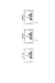
- FIG. 4 schematically shows the waveform of vibrations generated.
- vibration VB1 indicates vibration of a mechanical shutter.
- An exposure period is obtained by the so-called transition between the leading curtain and the trailing curtain, and vibrations due to this are generated at the timing after exposure.
- the vibration VB2 is an example in which the vibration of the mechanical shutter is generated in a pseudo manner by the vibrating section 32.
- the camera control section 30 causes the vibration section 32 to vibrate at the timing when the exposure period of the main exposure ends.
- the vibration unit 32 does not vibrate during the exposure period, and no blurring occurs in the still image.
- the camera control unit 30 causes the vibration unit 32 to vibrate at the timing when the image related to the main exposure is displayed on the display panel 4 or the viewfinder 5 after the exposure period of the main exposure ends. This is an example of By doing so, not only can vibration be avoided during the main exposure period, but also the user can recognize the image recorded as a still image without any deviation on the display.
- FIG. 5 shows the deviation between the actual scenery and the displayed image during imaging. Assume that exposure is performed on an actual scene as shown as frames F0, F1, F2, and F3.
- the exposure of the scenery shown in frame F1 becomes the main exposure.
- the image displayed on the viewfinder 5 or the like at that time is the image of frame F0, and is not an image recorded as a still image.
- the notification by vibration is made to be performed within the period in which the image of frame F1, which is the main exposure, is displayed.
- FIG. 6 shows the timing of processing up to display in the imaging device 100 during continuous shooting, with the horizontal direction as the time axis.
- exposure EX is the exposure of the image sensor in the image sensor section 12
- readout RD is the readout of the captured image signal from the image sensor section 12
- development DV is the development process by the camera signal processing section 13
- display dp is the image on the display section 15. It shows the display.
- Arrow PF indicates the flow of processing from exposure to display. That is, one frame of exposure EX is performed, after the exposure, readout RD of the captured image signal is performed, development DV is performed on the captured image signal, and through these processes, one frame of image is displayed dp.
- exposure EX and readout RD are repeatedly performed in the image sensor section 12. However, not all exposure is for still image recording, and exposure EX for displaying through images is also performed.
- the main exposure for still image recording (still image imaging exposure) is shown as "EXm" with diagonal lines.
- main exposures EXm1 and EXm2 are used.
- the image data of the frames of the main exposures EXm1 and EXm2 become image data that is recorded as a still image by the recording control section 14 or transmitted externally from the output section 16.
- the display period of the image of the frame of the main exposure EXm (EXm1, EXm2) is shown as a hatched display dpm (dpm1, dpm2).
- vibration for notification is performed during the display period of the image by main exposure as described above.
- vibration is generated within the display periods dpm1 and dpm2.
- the period of vibration performed in accordance with display dpm1 partially overlaps with the period of main exposure EXm2. Therefore, the still image obtained by the main exposure EXm2 may be blurred by the vibration VB10.
- the camera control unit 30 performs control to change the timing of main exposure when an overlap period occurs between the second and subsequent main exposure periods within the continuous shooting period and the display period of images corresponding to the previous main exposures. I do. More specifically, for example, it is possible to change the timing of the main exposure EXm2.
- FIG. 7 shows an example in which the start timing of main exposure EXm2 is shifted. By delaying the start timing of the main exposure EXm2 after the period indicated by the frame W1, it is prevented from overlapping with the period of display dpm1 of the image by the main exposure EXm1. As a result, vibration VB10 is not performed within the period of main exposure EXm2.
- the camera control unit 30 controls the timing of the vibration by the vibration unit 32 when the period of the second or later main exposure within the continuous shooting period overlaps with the display period of the image corresponding to the previous main exposure. Control to change. For example, as shown as vibration VBa2 in FIG. 6, the vibration is started at a timing earlier than the start timing of display dpm1, and the vibration is finished at the start timing tse of main exposure EXm2. This prevents vibration from occurring during the period of main exposure EXm2.
- the camera control unit 30 controls the period during which the vibration is performed by the vibration unit 32 when the period of the second and subsequent main exposures within the continuous shooting period overlaps with the display period of the image corresponding to the previous main exposure. Control is performed to shorten. For example, as shown as vibration VBa3 in FIG. 6, the vibration is started at the start timing of display dpm1, but the vibration is ended at the start timing tse of main exposure EXm2. This prevents vibration from occurring during the period of main exposure EXm2.
- the camera control unit 30 controls the intensity of the vibration by the vibration unit 32 when a period of overlap occurs between the second and subsequent main exposure periods within the continuous shooting period and the display period of the image corresponding to the previous main exposure. Performs weakening control. For example, as shown as vibration VBa4 in FIG. 6, vibration is performed within the period of display dpm1, but by weakening the intensity of the vibration at this time, even if it overlaps with exposure EXm2, it is less likely to have an influence.
- the camera control unit 30 prevents the vibration unit 32 from performing vibration when a period of overlap occurs between the second and subsequent main exposure periods within the continuous shooting period and the display period of images corresponding to the previous main exposures. Do it like this. For example, as shown as vibration VBa5 in FIG. 6, the exposure EXm2 is not affected by not causing vibration within the period of the display dpm1.
- the vibration will be adjusted to the main exposure in the case of continuous shooting, assuming that the vibration is performed in synchronization with the display timing of the still image. It is possible to have no influence (or weaken the influence), and to avoid deterioration in the quality of a series of still images obtained by continuous shooting.
- the camera control unit 30 can determine in advance whether or not the display dpm and the actual exposure EXm overlap during continuous shooting, and in which period the overlap occurs. That is, the frame rate, continuous shooting speed (number of frames: main exposure interval), and shutter speed setting (main exposure time) during continuous shooting are known before the start of continuous shooting. From these, the camera control unit 30 can calculate whether or not an overlap will occur during the continuous shooting period and the timing of the overlap period. For example, if the continuous shooting speed is lower than a predetermined value, no overlap occurs. If the continuous shooting speed is equal to or higher than a predetermined value, the overlapping timing may be calculated from the continuous shooting speed, frame rate, and shutter speed settings. Based on this, it is possible to change the main exposure timing in case (A1), change the vibration timing in (A2), or set the vibration period in (A3).
- FIG. 8 shows a case where the main exposure EXm for a relatively long time is performed according to the user's shutter operation ST due to the shutter speed setting. For example, assume a long-time exposure with an exposure time of about 1 second.
- vibration or sound notification is performed during the display period, as shown in vibration VB3 in FIG. 4.
- vibration is performed immediately after the shutter operation ST, such as vibration VB21.
- vibration is performed before exposure.
- the camera control unit 30 additionally switches the main exposure when performing main exposure for a predetermined time or longer in response to a still image capturing instruction such as shutter operation.
- the vibration unit 32 is controlled to vibrate even during the display dpm period of the image based on the captured image signal obtained by exposure. For example, as shown in vibration VB22 in FIG. 8, vibration is performed immediately after shutter operation ST, and also during the display dpm period. As a result, in addition to vibrations corresponding to the operation, vibrations are also performed to present a still image to be recorded.
- the camera control unit 30 controls the camera control unit 30 so that each vibration is performed in a different vibration mode. You can also do this.
- the vibration VB23 in FIG. 8 shows an example in which the vibration time is different between the vibration in response to the shutter operation ST and the vibration in response to the display dpm. This allows the user to understand the meaning of vibrations that correspond to operations and vibrations that indicate still images to be recorded.
- the different vibration modes may include changing the vibration intensity, changing the vibration pattern, or changing the vibration frequency. Further, differences may be made by combining vibration time, vibration intensity, vibration frequency, and vibration pattern.
- the camera control unit 30 controls the shutter operation, etc. when performing main exposure for a predetermined time or longer in response to a still image capturing instruction such as a shutter operation. Control is performed to start the main exposure after the vibration at the time of instructing to capture a still image has ended. This prevents vibration from affecting the main exposure EXm.
- the camera control unit 30 determines that the imaging device 100 is not being held by the user, the camera control unit 30 prevents one or both of vibrations during still image capture instructions such as shutter operation, and vibrations within the display dpm period. to control.
- the vibration Prevent notifications from being made. This is because when the user is not holding the main body casing 1, the user is less likely to feel the vibration, and the vibration does not function well as a notification.
- the notification may be made by sound as well as vibration. Furthermore, in the case of (B3'), the notification may be made by sound instead of vibration.
- the camera control unit 30 can determine the result of the imaging situation at a time before the notification.
- the imaging situation determination result is, for example, as follows. - Is image stabilization successful (normal) or unsuccessful (abnormal)? ⁇ Is the exposure appropriate (normal), or is it determined to be over or under exposure (abnormal)? ⁇ Is the tracking subject captured (normal) or is it lost (abnormal)? ⁇ Is it in focus (normal) or out of focus (abnormal)?
- some or all of these determination results are presented during the display dpm period. Note that since the period of the display dpm is instantaneous for the user, it is difficult to present in detail whether each period is normal or abnormal. Therefore, for example, the user may be able to select which of the above determination results to present. Alternatively, for the plurality of determinations described above, if all of the determinations are normal, it is determined to be "normal”, and if any one of the determinations is abnormal, "abnormal" may be presented.
- the display dpm is performed for the image of the main exposure EXm.
- the camera control unit 30 controls the vibration VB30 if it is "normal”, and controls the vibration VB31 if it is "abnormal". Control. This allows the user to immediately know whether the still image captured by the shutter operation has been successfully captured or failed.
- Sound notification may be provided in conjunction with the vibrations VB30 and VB31. In that case, by making the sound for vibration VB30 and the sound for vibration VB31 different sounds, it is possible to present to the user whether the imaging is normal or abnormal. Note that the presentation may be performed using sound instead of using vibration.
- FIG. 10 is an example in which the determination result of the imaging situation is presented by changing the display mode of the entire still image.
- a normal display mode is shown as a through image, as well as a case of normal presentation and a case of abnormal presentation.
- normal presentation in the figure, the entire screen of the through image is dotted, but for example, it is assumed that the entire screen is displayed in see-through blue.
- abnormality presentation the entire screen of the live-through image is shaded, but the entire screen is displayed in see-through red, for example. By doing this, the user can visually recognize the contents of the subject and recognize whether it is normal or abnormal depending on whether the overall color is blue or red.
- the displayed image changes every frame, but as shown in FIG. 11, if an entirely blue image is displayed after the shutter operation ST, the user can It can be recognized that the still image capturing by ST was successful. Further, as shown in FIG. 12, if an entirely red image is displayed after the shutter operation ST, the user can recognize that the still image capturing by the shutter operation ST has failed.
- FIG. 13 is an example in which the determination result of the imaging situation is presented by changing the display mode of the peripheral area in the still image.
- the frame-shaped peripheral area 60 is displayed in see-through blue for normal presentation, and the frame-shaped peripheral area 60 is displayed in see-through red for abnormal presentation. It is a case.
- This example also appears in the through image, making it easy for the user to recognize the success or failure of imaging.
- by presenting the image in the peripheral area 60 there is an advantage that the subject can be easily recognized in the central area.
- FIGS. 14 and 15 are examples of changing the display mode depending on the amount of abnormality in under- or over-exposure situations.
- FIG. 14 when the image is normal, a normal live view image is displayed, but when the exposure is underexposed, the intensity of blue in the peripheral area 60 is changed according to the amount of abnormality. Furthermore, in the case of overexposure, the intensity of red in the peripheral area 60 is changed depending on the amount of abnormality.
- the user can recognize under/over conditions based on the color of the peripheral area 60, and can recognize the degree of abnormality based on the darkness of the color.
- FIG. 15 is an example in which the size of the peripheral area 60 to be colored blue or red is changed depending on the amount of abnormality in under- or over-exposure situations. If it is normal, a normal through image is displayed, but if the exposure is underexposed, the size of the blue peripheral area 60 (width of the frame) is changed depending on the amount of abnormality. If the exposure is overexposed, the size of the red peripheral area 60 (width of the frame) is changed depending on the amount of abnormality. With such a display, the user can recognize under/over conditions based on the color of the peripheral area 60, and can recognize the degree of abnormality based on the size of the colored area.
- a similar display may be made depending on the amount of abnormality in the front focus, back focus, etc. of the in-focus state (focus). Furthermore, a similar display can be made depending on the amount of image blur due to camera shake during exposure or shaking of the main body housing 1.
- Vibration according to lens barrel> When performing vibration as a notification during the display dpm period, etc. in response to the shutter operation, etc. described above, or as a presentation of the determination result of the imaging situation, depending on the lens barrel 2 attached.
- the vibration mode may also be changed by
- the weight and center of gravity differ depending on the lens barrel 2 attached. Then, depending on the attached lens barrel 2, it may be difficult for the user to sense vibrations.
- the camera control unit 30 may change the vibration mode depending on the type of the lens barrel 2.
- the camera controller 30 can acquire information such as the model number and type of the lens barrel 2 through communication with the lens barrel controller 23 . Therefore, the vibration mode at the time of vibration is selected depending on the lens barrel 2. This allows the user to appropriately perceive vibrations regardless of the lens barrel 2.
- the vibration mode to be changed includes vibration intensity, vibration frequency, length of vibration period, vibration pattern, and the like.
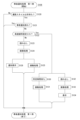
- the camera control unit 30 determines in step S101 whether the current shooting style is hand-held.
- the camera control unit 30 can determine whether the camera is in a hand-held state, for example, based on the detection information of the IMU of the sensor unit 33 or the touch sensor.
- the camera control unit 30 The process advances from step S101 to step S105. This corresponds to the process (B3') described above.
- step S102 determines whether the scheduled time for the current main exposure is equal to or longer than the predetermined time thT. In other words, it is determined whether the exposure at the currently set shutter speed is a long exposure. The reason for determining whether or not it is a long exposure is for the above-mentioned process (B1).
- step S105 If it is not a long exposure, the process advances to step S105. If it is a long exposure, the camera control unit 30 proceeds to step S103 and controls the operation reception vibration. That is, control is performed to cause the vibrating section 32 to perform vibrations corresponding to the shutter operation, etc. as explained in the vibrations VB21, VB22, and VB23 in FIG.
- step S104 the camera control unit 30 waits for the vibration unit 32 to stop vibrating.
- the process advances to step S105. This is to ensure that the main exposure EXm is performed after the vibration as described in (B3) above.
- the camera control unit 30 causes the image sensor unit 12 to execute the main exposure EXm when proceeding to step S105 from any one of steps S101, S102, and S104. Thereafter, in step S106, post-notification processing is performed as control until the display period of the image related to the main exposure EXm. Although the details of the post-notification process will be described later, the vibration control described in (A1) to (A5) or (B1), (B2), and (B2') above is performed by this post-notification process.
- step S107 the camera control unit 30 determines whether continuous shooting is being continued. In the case of single-shot imaging or when the continuous shooting operation has been completed, the camera control unit 30 ends the process from step S107.
- the camera control unit 30 returns from step S107 to step S104 and waits for the vibration to stop.
- the standby in this case is a standby for vibration to be performed at the display dpm.
- the start of the main exposure EXm is delayed so that the vibration and the main exposure EXm do not overlap.
- the camera control unit 30 starts the main exposure in step S105.
- FIG. 17 is a second example of notification control processing. Note that in each flowchart, the same step numbers are given to processes similar to those described above to avoid redundant explanation.
- the second example in FIG. 17 differs from the first example in that the vibration stop standby in step S104 is not performed.
- Other processing is the same.
- this second process example can be considered.
- the camera control unit 30 determines in step S120 whether the current shooting style is hand-held. If the camera is not in hand, the camera control unit 30 ends the post-notification process. In other words, in this case, notification of vibration, etc. during the display dpm period is not performed. This also corresponds to the process (B3') described above.
- the camera control unit 30 proceeds to step S121 and determines whether or not prior notification has been given regarding the current still image capturing.
- the prior notification here refers to a notification by vibration in response to a shutter operation or the like in the case of long exposure. Specifically, this is the vibration executed in step S103 in FIG.
- the camera control unit 30 ends the post-notification process. In other words, in this case, notification of vibration, etc. during the display dpm period is not performed. As a result, as in the process (B1) described above, in the case of long exposure, vibration in accordance with the display dpm1 is not performed.
- step S102 advances from step S102 to step S105.
- the camera control unit 30 proceeds from step S121 to step S122 and subsequent steps in FIG. 18, and controls vibration in accordance with the display dpm.
- the camera control unit 30 determines whether or not the current imaging is based on the high-speed continuous shooting setting.
- the user can select the continuous shooting speed.
- Continuous shooting at a certain continuous shooting speed or higher is defined as high-speed continuous shooting.
- the high-speed continuous shooting referred to here is a continuous shooting speed at which the display dpm periods of images related to the second and subsequent main exposures of the continuous shooting period and the previous main exposures overlap.
- the process advances to step S123.
- step S123 the camera control unit 30 causes the readout of the captured image signal by the main exposure in the previous step S105 (FIGS. 16 and 17), and in step S124 causes the camera signal processing unit 13 to execute development processing.
- step S126 the display unit 15 executes display dpm of the image related to the main exposure EXm.
- the camera signal processing unit 13 controls the vibration unit 32 to perform vibration in parallel in step S125.
- the vibration processing will be described later.
- steps S125 and S126 the still image to be recorded is displayed on the display unit 15, and a notification is provided by vibration in accordance with the display period. In other words, the vibration is as explained in FIG.
- the camera signal processing unit 13 may perform control to display the image to be displayed in a display mode that presents the determination result of the imaging situation, as described in FIGS. 10 to 15. can. That is, the display mode in display dpm is controlled according to the result of the development process in step S124.
- step S122 If it is determined in step S122 that high-speed continuous shooting is set, the camera control unit 30 proceeds to steps S130 and S132. This is a case where during continuous shooting, there is a possibility that the actual exposure EXm overlaps with the display dpm period of the image related to the previous actual exposure.
- step S132 the camera control unit 30 causes the captured image signal to be read out by the main exposure in the previous step S105 (FIGS. 16 and 17), and in step S133, the camera signal processing unit 13 executes the development process.
- step S134 the camera control section 30 causes the display section 15 to execute display dpm of the image related to the main exposure EXm.
- step S134 the camera signal processing unit 13 can perform control to display the image to be displayed in a display mode that presents the determination result of the imaging situation. That is, the display mode in display dpm is controlled according to the result of the development process in step S133.
- the camera control unit 30 waits for a predetermined timing in step S130, and then performs vibration processing in step S131.
- the vibration processing in this case is one of (A2), (A3), and (A4), or a combination of them.
- the predetermined time period for waiting in step S130 is the time period up to a point slightly before the display dpm start timing.
- the predetermined waiting time in step S130 is the time until the display dpm start timing.
- step S106 in the first example of the notification control process in FIG. 16 when the post-notification process in FIG. 18 is performed, the exposure timing of the main exposure EXm is not changed in the case of high-speed continuous shooting, and (A2) ( Either A3) or A4 will be executed.
- step S106 in the second example of the notification control process in FIG. 17 when the post-notification process in FIG. 18 is performed, in the case of high-speed continuous shooting, the timing change of main exposure , (A2), (A3), and (A4) are executed in combination.
- FIG. 19 shows a second example of the post-notification process.
- the second example in FIG. 19 is obtained by removing step S121 from the first example in FIG. Step S121 is a process for not performing notification in accordance with the display dpm when advance notification is performed.
- the notification is performed in accordance with the display dpm1 regardless of whether advance notification is executed or not.
- the second example in FIG. 19 is the process described as (B2), and in the case of long exposure, the camera control unit 30 generates both vibrations in response to shutter operation etc. and vibrations during the display dpm period. will be controlled so that it is executed.
- the steps after step S122 are the same as those in FIG. 18.
- the camera control unit 30 performs control to make the vibration mode in step S125 different from the vibration mode in step S103 in FIG. is the process explained in (B2') above.
- FIG. 20 shows a third example of the post-notification process. This differs from the second example in FIG. 19 in the processing when the high-speed continuous shooting setting is turned on.
- the camera control unit 30 ends the post-notification process. In other words, notifications matching the display dpm are not executed. As explained in (A5), this is an example in which vibration notification is not performed when the display dpm period and the main exposure EXm period overlap due to high-speed continuous shooting.
- vibration notification is not performed, but control is performed to display the image to be displayed in a display mode that presents the determination result of the imaging situation. You may also do so.
- FIGS. 18, 19, and 20 above an example is described in which vibration is performed in accordance with the display dpm in step S125 or step S134, but a processing example in which vibration is not performed is also possible. That is, when displaying in steps S126 and S134, a display mode is executed in which the determination result of the imaging situation is presented, as described in FIGS. In some cases, vibration is not performed. Further, in this case, notification by sound may be performed.
- FIG. 21 shows a first example of vibration processing.
- the camera control unit 30 checks whether the high-speed continuous shooting setting is on in step S150, and if the high-speed continuous shooting setting is not set, that is, in the case of imaging with the low-speed continuous shooting setting or single-shot imaging, the camera control unit 30 turns on the normal vibration in step S151. Vibration control is performed as follows.
- the normal vibration in this case means a vibration with a normal vibration duration set as a vibration notification.
- the camera control unit 30 performs vibration control as a short vibration in step S152. Short vibrations are vibrations whose duration is shorter than the above-mentioned normal vibrations.
- the normal vibration and the short vibration only need to differ in at least the vibration duration time, but in addition, the vibration frequency, pattern, and vibration intensity may also be different.
- FIG. 22 shows a second example of vibration processing.
- the camera control unit 30 checks whether the high-speed continuous shooting setting is on in step S150, and if the high-speed continuous shooting setting is not set, that is, in the case of imaging with the low-speed continuous shooting setting or single-shot imaging, the camera control unit 30 turns on the normal vibration in step S155. Vibration control is performed as follows.
- the normal vibration in this case means a vibration with a normal vibration intensity set as a vibration notification.
- the camera control unit 30 performs vibration control as a weak vibration in step S156. Weak vibration is vibration whose vibration intensity is weaker than the above-mentioned normal vibration.
- the normal vibration and the weak vibration only need to be different in at least the vibration intensity, but in addition, the vibration frequency, pattern, and vibration duration may be different.
- FIG. 23 shows a third example of vibration processing.
- the determination result of the imaging situation is presented by vibration during display dpm.
- step S160 the camera control unit 30 determines whether the image to be displayed is normal or abnormal as a result of the development process. If it is normal, the camera control unit 30 performs vibration control set as normal vibration in step S161. If it is abnormal, the camera control unit 30 performs vibration control set as abnormal vibration in step S162.
- Normal vibration and abnormal vibration are vibrations with different vibration modes. For example, it is assumed that at least one of the vibration duration, vibration intensity, vibration frequency, vibration pattern, etc. is different from each other.
- step S125 or step S131 in the process of FIG. 18 or 19 normality/abnormality of the image is presented depending on the vibration mode.
- presentation using displays such as those shown in FIGS. 10 and 11 may be performed, or only presentation using vibration may be performed.
- FIG. 24 shows a fourth example of vibration processing.
- three values are presented as a result of determination of the imaging situation using vibrations during display dpm.
- the three values are three values indicating normal, under, and over.
- In the in-focus state there are three values indicating normal, front focus, and back focus.
- step S170 the camera control unit 30 determines the development processing result of the image to be displayed. For example, the exposure state is determined. If it is under, the camera control unit 30 performs vibration control set as under-side abnormal vibration in step S171. If it is normal, the camera control unit 30 performs vibration control set as normal vibration in step S172. If it is over, the camera control unit 30 performs vibration control set as over-side abnormal vibration in step S173. I do.
- the normal vibration, the abnormal underside vibration, and the abnormal overside vibration are vibrations with different vibration modes. For example, it is assumed that at least one of the vibration duration, vibration intensity, vibration frequency, vibration pattern, etc. is different from each other.
- the exposure situation is presented according to the vibration mode.
- presentation using displays such as those shown in FIGS. 14 and 15 may be performed, or only presentation using vibration may be performed.
- FIG. 25 shows a fifth example of vibration processing. This is an example in which the vibration mode is changed depending on the type of lens barrel 2.
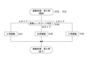
- step S180 the camera control unit 30 refers to the code indicating the type of the attached lens barrel 2 and branches the process.
- the camera controller 30 communicates with the lens barrel controller 23 to acquire a code indicating the type and model number of the lens barrel 2. Further, the camera control unit 30 stores table data as shown in FIG. 26 in the memory unit 31, for example. This table data is information indicating the vibration type corresponding to the lens type code.
- the camera control unit 30 can determine the type of the lens barrel 2 currently being attached by referring to this table data. If the camera control unit 30 determines that it is type A based on the type code, it performs the vibration control set for type A in step S181. Further, if the camera control unit 30 determines that it is type B based on the type code, it performs vibration control set for type B in step S182. Further, if the camera control unit 30 determines that the camera is type C based on the type code, it performs vibration control set for type C in step S183.
- the vibration settings of types A, B, and C are vibrations with different vibration modes. For example, it is assumed that at least one of the vibration duration, vibration intensity, vibration frequency, vibration pattern, etc. is different from each other.
- types A, B, and C are set according to the weight, center of gravity, material, structure, etc. of the lens barrel 2, and are vibration settings intended to allow the user to accurately sense vibrations.
- the imaging device of the embodiment includes an image sensor unit 12 that exposes incident light and outputs a captured image signal, a vibration unit 32 as a notification unit, and an image sensor unit that generates a still image in response to a still image imaging instruction.
- the camera controller 30 includes a camera control unit 30 that controls a notification unit (vibration unit 32) to execute a notification corresponding to the main exposure (still image capturing exposure) performed by the unit 12 in a period different from the exposure period of the main exposure.
- the vibration unit 32 is mainly cited as an example of the notification unit, and the user is notified by vibration, but instead of vibration, or in addition to vibration, notification by sound such as an electronic sound or shutter sound, or notification by display can also be used. In some cases, notifications may be provided by emitting light from an LED or the like.
- the camera control unit 30 may control the notification unit to perform the notification in a period different from the exposure period of the main exposure. Further, the mode of notification can be changed in the same way as in the case of the vibrating section 32. For example, there are differences in pitch, timbre, melody, and voice, differences in light emission patterns, light emission intensity, and light emission cycles, and differences in display content.
- the camera control unit 30 controls an example in which the vibration unit 32 performs vibration corresponding to the main exposure within a display period of an image based on a captured image signal obtained by the main exposure.
- the captured image signal read out from the image sensor unit 12 is developed in the camera signal processing unit 13, and then an image based on the captured image signal is displayed on the viewfinder 5 or It is displayed on the display panel 4.
- the user can recognize that the image displayed at the time of vibration is an image to be recorded (or transmitted) as a still image.
- the user can recognize which image is being recorded by the vibrations while a series of scenes are displayed as through images during continuous shooting.
- the camera control unit 30 controls the main exposure when an overlapping period occurs between the second and subsequent main exposure periods within the continuous shooting period and the display period of the image corresponding to the previous main exposure.
- An example of controlling to change the timing has been described (processing (A1)).
- the period of a certain still image shooting exposure may overlap with the display period of the image from the previous still image shooting exposure (main exposure EXm).
- main exposure EXm main exposure
- vibrations may occur during exposure, which may cause blur in the recorded still image. Therefore, the timing of still image imaging exposure is changed to avoid overlapping periods (see FIGS. 8 and 16).
- FIGS. 8 and 16 As a result, even in the case of continuous shooting, it is possible for the user to match the display timing of the vibration and the still image to be recorded, and to prevent blurring from occurring in the still image.
- the camera control unit 30 controls the vibration unit 32 when an overlap period occurs between the second and subsequent main exposure periods within the continuous shooting period and the display period of the image corresponding to the previous main exposure.
- An example has been described in which control is performed to change the timing of vibration (process (A2), vibration VBa2 in FIG. 6, see FIG. 18).
- the vibration timing is changed to avoid the overlap of the periods.
- the user even in the case of continuous shooting, it is possible for the user to make the vibration and the display timing of the recorded still image approximately coincide with each other, and to prevent blurring from occurring in the still image.
- Another advantage is that high-speed continuous shooting performance is not degraded by not changing the timing of main exposure.
- both the vibration timing and the main exposure timing may be changed so that they do not overlap. For example, if a relatively large change in vibration timing is required and there is a large discrepancy between display and vibration, it may be possible to shift the exposure timing to bring the vibration and display timing closer together. For example, it is possible to advance the vibration timing by half the overlapping period length and delay the start of the next main exposure by half the time.
- the camera control unit 30 controls the vibration unit 32 when an overlap period occurs between the second and subsequent main exposure periods within the continuous shooting period and the display period of the image corresponding to the previous main exposure.
- An example has been described in which control is performed to shorten the execution period of vibration (process (A3), vibration VBa3 in FIG. 6, see FIG. 21).
- process (A3), vibration VBa3 in FIG. 6, see FIG. 21) As a result, even in the case of continuous shooting, it is possible for the user to make the vibration and the display timing of the recorded still image approximately coincide with each other, and to prevent blurring from occurring in the still image.
- Another advantage is that high-speed continuous shooting performance is not degraded by not changing the timing of main exposure.
- the camera control unit 30 controls the vibration unit 32 when an overlap period occurs between the second and subsequent main exposure periods within the continuous shooting period and the display period of the image corresponding to the previous main exposure.
- An example has been described in which control is performed to weaken the intensity of vibration caused by (processing (A4), vibration VBa4 in FIG. 6, see FIG. 22).
- processing (A4), vibration VBa4 in FIG. 6, see FIG. 22 To extremely reduce the possibility that a still image will be affected by blur by weakening the intensity of vibration.
- Another advantage is that high-speed continuous shooting performance is not degraded by not changing the timing of main exposure.
- the camera control unit 30 controls the vibration unit 32 when an overlap period occurs between the second and subsequent main exposure periods within the continuous shooting period and the display period of the image corresponding to the previous main exposure.
- An example has been described in which control is performed to prevent vibration from being performed (process (A5), vibration VBa5 in FIG. 6, see FIG. 20). Thereby, it is possible to prevent blur from occurring in still images obtained by continuous shooting. There is also the advantage that high-speed continuous shooting performance is not degraded by not changing the timing of main exposure.
- the camera control unit 30 controls the presence or absence of notification by the notification unit such as the vibration unit 32 or the execution timing of the notification, depending on the exposure time of still image imaging exposure. More specifically, in the embodiment, when performing main exposure for less than a predetermined time in response to a still image capturing instruction, camera control unit 30 displays an image based on a captured image signal obtained by main exposure. The vibration unit 32 is controlled to perform vibration corresponding to the main exposure within the period. On the other hand, when performing main exposure for a predetermined time or longer in response to a still image imaging instruction, the vibration unit 32 performs the main exposure for a predetermined time or longer, regardless of whether the vibration at the time of the still image imaging instruction is within the still image imaging exposure period.
- the vibration in this case may occur before the start of exposure, but may occur at the time of starting exposure.
- the exposure is for a long time, even if the image vibrates for some time during the exposure, there is almost no effect of blurring due to the vibration, so it can be considered that there is no problem.
- the camera control unit 30 when performing main exposure for a predetermined time or more in response to a still image imaging instruction, uses a captured image signal obtained by the main exposure in addition to the vibration at the time of the still image imaging instruction.
- An example has been described in which the vibration corresponding to the main exposure is controlled to be performed by the vibration unit 32 even during the display period of the image based on the image (see the process in (B2), the vibration VB22 in FIG. 8, and FIG. 19).
- the main exposure is a long exposure, in addition to performing vibration immediately in response to the shutter operation (see step S103 in FIG. 16), vibration is also performed during the display period during which the main exposure image is displayed. (Step S125 or S131 in FIG. 19). This eliminates the discomfort caused by vibration, and also allows the user to vibrate during the still image display period, making it easier for the user to understand the still image to be recorded.
- the camera control unit 30 causes the vibration unit 32 to perform vibration in response to a still image capturing instruction, and causes the vibration unit 32 to perform vibration within an image display period based on a captured image signal obtained by main exposure.
- An example has been described in which the vibration is controlled to have a different vibration mode (process (B2'), see vibration VB24 in FIG. 8).
- the vibration in response to the shutter operation and the vibration during the display period are made to differ, for example, in vibration time, vibration intensity, vibration pattern, etc. This allows the user to feel the difference in meaning of each vibration.
- the camera control unit 30 when performing main exposure for a predetermined time or more in response to a still image capturing instruction, performs control to start the main exposure after the vibration at the time of the still image capturing instruction ends.
- An example has been described (see the process (B3) and steps S104 and S105 in FIG. 16). If vibration is performed immediately in response to a shutter operation, and the vibration period and the main exposure period overlap, there is a possibility that a still image will be affected by blur depending on the case. Therefore, the main exposure is started after the vibrations caused by the shutter operation have subsided. This can prevent blurring due to vibration.
- the camera control unit 30 determines that the user is not holding the camera hand-held, the camera control unit 30 generates vibrations when instructing to capture a still image, or vibrations during an image display period based on a captured image signal obtained by main exposure.
- control is performed so as not to execute one or both of the following (see the process (B3'), step S101 in FIG. 16, and step S120 in FIG. 18).
- the imaging device 100 is attached to a tripod to capture an image or when an operation is performed using a remote controller, even if the main body casing 1 is vibrated, the user is not notified. Therefore, notification is made only when hand-held imaging is performed to avoid unnecessary vibrations. Note that either one of the vibrations in response to the shutter operation and the vibrations during the display period may be performed. This is because even if a tripod or the like is used, the user may still be touching the main body casing 1, for example.
- the camera control unit 30 performs control to present the determination result of the imaging situation during the display period of the image based on the captured image signal obtained by the main exposure. For example, after the shutter operation is performed, main exposure is performed, after the main exposure, development processing is performed, and then the still image is displayed. Therefore, the imaging situation can be determined during display. Therefore, the imaging situation is presented in a display manner (see FIGS. 10 to 15). This allows the user to know the imaging situation immediately or during continuous shooting. It has also been described that the vibration performed during image display is presented based on the determination result of the imaging situation (see FIGS. 9, 23, and 24). That is, changing the vibration mode depending on the imaging situation while displaying an image is also an example of control for displaying an image based on a captured image signal in a manner that presents the determination result of the imaging situation. This also allows the user to know the imaging situation.
- the situation of image stabilization As the determination result of the imaging situation, the situation of image stabilization, the situation of overexposure, the situation of underexposure, the tracking of a tracked subject, the situation of lost, and the situation of in-focus and out-of-focus are listed. Since these situations can be determined at the development processing stage, they are suitable for simultaneous display during static display. This also gives the user an opportunity to immediately improve the situation.
- the camera control unit 30 presents the determination result of the imaging situation by changing the display mode of the entire still image.
- the camera control unit 30 presents the determination result of the imaging situation on the entire screen as shown in FIG. 10, it becomes easier for the user to recognize even a momentary image during live view display.
- the camera control unit 30 causes the determination result of the imaging situation to be presented by changing the display mode of the peripheral area in the still image.
- Figure 13 by displaying the subject normally in the central area of the screen and presenting the imaging situation in the display mode of the peripheral area, visibility of the subject is ensured, while the momentary image during the through image display is displayed. Even if there is, the user can easily recognize the imaging situation.
- the camera control unit 30 changes the display mode in stages according to the determination result of the imaging situation.
- the user can recognize the degree of abnormality in the imaging situation.
- the camera control unit 30 determines the vibration mode of the vibration unit 32 by the type of the lens barrel 2 attached to the main body housing 1.
- An example of setting according to information has been given (see FIGS. 25 and 26). The way the user feels the vibration changes depending on the weight, center of gravity, etc. of the lens barrel 2.
- notifications using vibrations have been mainly described, but instead of notifications using vibrations, or in addition to notifications using vibrations, notifications using sounds may be performed. For example, by making an electronic sound, a sound resembling a shutter operation, or the like during the display dpm period, it is possible to obtain the effect of clearly showing the still image to be recorded to the user.
- the program of the embodiment is a program that causes a CPU, a DSP, etc., or a device including these, to execute the processes described in FIGS. 16 to 25, for example. That is, the program of the embodiment includes arithmetic processing for controlling the imaging device 100, which includes an imaging device section 12 that exposes incident light and outputs a captured image signal, and a notification section (for example, a vibration section 32 that vibrates the housing).
- This is a program that causes a device (for example, the camera control unit 30) to execute processing.
- the program sends a notification by vibration or the like corresponding to still image imaging exposure performed by the image sensor unit 12 to generate a still image in response to a still image imaging instruction, and determines the exposure period of the still image imaging exposure.
- This causes the arithmetic processing unit to execute the control that is executed by the notification unit during different periods. With such a program, the imaging device 100 of the present disclosure can be easily implemented using an arithmetic processing device.
- Such a program can be recorded in advance in an HDD (Hard Disk Drive) as a recording medium built into equipment such as a computer device, or in a ROM in a microcomputer having a CPU.
- a flexible disk, a CD-ROM (Compact Disc Read Only Memory), an MO (Magneto Optical) disk, a DVD (Digital Versatile Disc), a Blu-ray Disc (registered trademark), a magnetic disk, a semiconductor memory It can be stored (recorded) temporarily or permanently in a removable recording medium such as a memory card.
- a removable recording medium can be provided as so-called package software.
- a program into a personal computer or the like from a removable recording medium, it can also be downloaded from a download site via a network such as a LAN (Local Area Network) or the Internet.
- LAN Local Area Network
- an image sensor unit that exposes incident light and outputs a captured image signal
- notification department Control that causes the notification unit to execute a notification corresponding to still image imaging exposure performed by the image sensor unit in order to generate a still image in response to a still image imaging instruction, in a period different from an exposure period of the still image imaging exposure.
- An imaging device comprising: a control unit that performs the above operations; (2) The notification unit is a vibration unit that vibrates the housing, The control unit includes: The imaging according to (1) above, wherein the vibration corresponding to the still image imaging exposure is controlled to be performed by the vibration unit within a display period of an image based on the captured image signal obtained by the still image imaging exposure.
- Device includes: The imaging according to (1) above, wherein the vibration corresponding to the still image imaging exposure is controlled to be performed by the vibration unit within a display period of an image based on the captured image signal obtained by the still image imaging exposure.
- the control unit includes: When there is an instruction to continuously capture still images as the still image capture instruction, When an overlapping period occurs between the second and subsequent still image imaging exposure periods within the continuous shooting period and the display period of images corresponding to the previous still image imaging exposures, the timing of the still image imaging exposures is adjusted.
- the imaging device according to (2) above which performs control to change.
- the control unit includes: When there is an instruction to continuously capture still images as the still image capture instruction, When an overlapping period occurs between the second and subsequent still image imaging exposure periods within the continuous shooting period and the display period of images corresponding to the previous still image imaging exposures, the timing of vibration by the vibration section is adjusted.
- the control unit includes: When there is an instruction to continuously capture still images as the still image capture instruction, In the case where an overlapping period occurs between the second and subsequent still image imaging exposure periods within the continuous shooting period and the display period of an image corresponding to the previous still image imaging exposure, the period during which the vibration is performed by the vibration section.
- the imaging device according to any one of (2) to (4) above, wherein the imaging device performs control to shorten.
- the control unit includes: When there is an instruction to continuously capture still images as the still image capture instruction, When an overlapping period occurs between the second and subsequent still image imaging exposure periods within the continuous shooting period and the display period of images corresponding to the previous still image imaging exposures, the intensity of vibration by the vibrating section is adjusted.
- the imaging device according to any one of (2) to (5) above, which performs weakening control.
- the control unit includes: When there is an instruction to continuously capture still images as the still image capture instruction, When an overlapping period occurs between the second and subsequent still image capturing exposure periods within the continuous shooting period and the display period of images corresponding to the previous still image capturing exposures, the vibration unit does not cause vibration.
- the imaging device which performs control.
- the control unit controls whether or not the notification unit makes a notification corresponding to the still image imaging exposure or the execution timing of the notification, depending on the exposure time of the still image imaging exposure.
- An imaging device according to claim 1.
- the control unit includes: When performing the still image imaging exposure for less than a predetermined time in response to the still image imaging instruction, the still image imaging exposure is performed within a display period of an image based on a captured image signal obtained by the still image imaging exposure. controlling a corresponding notification to be executed by the notification unit; When the still image imaging exposure is performed for a predetermined time or more in response to the still image imaging instruction, the notification section is controlled to perform notification at the time of the still image imaging instruction. Imaging device.
- the control unit includes: When performing the still image imaging exposure for a predetermined time or more in response to the still image imaging instruction, In addition to the notification at the time of the still image imaging instruction, the notification unit executes a notification corresponding to the still image imaging exposure within a display period of an image based on a captured image signal obtained by the still image imaging exposure.
- the control unit includes: a notification at the time of the still image capturing instruction; The imaging device according to (10) above, wherein the imaging device is controlled so that the notification executed by the notification unit within a display period of an image based on the captured image signal obtained by the still image imaging exposure is in a different manner.
- the notification unit is a vibration unit that vibrates the housing,
- the control unit includes: When performing the still image imaging exposure for a predetermined time or more in response to the still image imaging instruction, The imaging device according to any one of (9) to (11) above, wherein control is performed to start the still image imaging exposure after the vibration as a notification at the time of the still image imaging instruction ends.
- the notification unit is a vibration unit that vibrates the housing, The control unit includes: If it is determined that the item is not held by the user, Control not to perform one or both of the vibration as a notification at the time of the still image imaging instruction or the vibration as a notification within the display period of the image based on the captured image signal obtained by the still image imaging exposure.
- the imaging device according to any one of 9) to (12).
- the control unit includes: The imaging device according to any one of (1) to (13) above, wherein control is performed to present a determination result of an imaging situation during a display period of an image based on a captured image signal obtained by the still image imaging exposure.
- the determination result of the imaging situation is: Image stabilization status, Overexposure and underexposure situations, Tracking subject tracking, lost status, In-focus/out-of-focus situation,
- the imaging device according to (14) above including any one of the determination results.
- the imaging device according to (14) or (15), wherein the control unit presents the determination result of the imaging situation by changing a display mode of a peripheral area in a still image.
- the control unit includes: The imaging device according to any one of (14) to (17) above, wherein the display mode is changed in stages according to the determination result of the imaging situation.
- the housing has a structure in which the lens barrel can be replaced, The control unit includes: The vibration mode of the vibration section is set according to the type information of the lens barrel attached to the housing. (2) (3) (4) (5) (6) (7) (11) (12) ) (13).
- an image sensor unit that exposes incident light and outputs a captured image signal; notification department As a control method for an imaging device equipped with Control that causes the notification unit to execute a notification corresponding to still image imaging exposure performed by the image sensor unit in order to generate a still image in response to a still image imaging instruction, in a period different from an exposure period of the still image imaging exposure.
- a control method for an imaging device equipped with Control that causes the notification unit to execute a notification corresponding to still image imaging exposure performed by the image sensor unit in order to generate a still image in response to a still image imaging instruction, in a period different from an exposure period of the still image imaging exposure.
- notification department As a control method for an imaging device equipped with Control that causes the notification unit to execute a notification corresponding to still image imaging exposure performed by the image sensor unit in order to generate a still image in response to a still image imaging instruction, in a period different from an exposure period of the still image imaging exposure.
Landscapes
- Engineering & Computer Science (AREA)
- Multimedia (AREA)
- Signal Processing (AREA)
- Physics & Mathematics (AREA)
- General Physics & Mathematics (AREA)
- Studio Devices (AREA)
Priority Applications (2)
| Application Number | Priority Date | Filing Date | Title |
|---|---|---|---|
| US18/850,770 US20250227381A1 (en) | 2022-05-12 | 2023-04-19 | Imaging device, control method, and program |
| JP2024520335A JPWO2023218884A1 (https=) | 2022-05-12 | 2023-04-19 |
Applications Claiming Priority (2)
| Application Number | Priority Date | Filing Date | Title |
|---|---|---|---|
| JP2022-078695 | 2022-05-12 | ||
| JP2022078695 | 2022-05-12 |
Publications (1)
| Publication Number | Publication Date |
|---|---|
| WO2023218884A1 true WO2023218884A1 (ja) | 2023-11-16 |
Family
ID=88730197
Family Applications (1)
| Application Number | Title | Priority Date | Filing Date |
|---|---|---|---|
| PCT/JP2023/015646 Ceased WO2023218884A1 (ja) | 2022-05-12 | 2023-04-19 | 撮像装置、制御方法、プログラム |
Country Status (3)
| Country | Link |
|---|---|
| US (1) | US20250227381A1 (https=) |
| JP (1) | JPWO2023218884A1 (https=) |
| WO (1) | WO2023218884A1 (https=) |
Families Citing this family (2)
| Publication number | Priority date | Publication date | Assignee | Title |
|---|---|---|---|---|
| JP2023154673A (ja) * | 2022-04-07 | 2023-10-20 | キヤノン株式会社 | 撮像装置およびその制御方法 |
| JP2025033652A (ja) * | 2023-08-30 | 2025-03-13 | キヤノン株式会社 | 画像処理装置、撮像装置、画像処理方法、およびプログラム |
Citations (3)
| Publication number | Priority date | Publication date | Assignee | Title |
|---|---|---|---|---|
| JP2006333310A (ja) * | 2005-05-30 | 2006-12-07 | Konica Minolta Holdings Inc | 携帯通信装置 |
| WO2016178267A1 (ja) * | 2015-05-01 | 2016-11-10 | オリンパス株式会社 | 撮像指示装置、撮像システム、撮影方法およびプログラム |
| JP2017216628A (ja) * | 2016-06-01 | 2017-12-07 | キヤノン株式会社 | 通信装置、通信装置の制御方法、及び、プログラム |
Family Cites Families (8)
| Publication number | Priority date | Publication date | Assignee | Title |
|---|---|---|---|---|
| US11202011B2 (en) * | 2016-07-25 | 2021-12-14 | Canon Kabushiki Kaisha | Control apparatus, image capturing apparatus, lens apparatus, image capturing system, control method, and storage medium |
| US11095818B2 (en) * | 2017-10-30 | 2021-08-17 | Sony Corporation | Vibration generation device and vibration control method |
| JP7330715B2 (ja) * | 2018-04-03 | 2023-08-22 | キヤノン株式会社 | 電子機器、電子機器の制御方法およびプログラム |
| JP7222396B2 (ja) * | 2018-07-20 | 2023-02-15 | 株式会社ニコン | カメラアクセサリおよび情報送信方法 |
| CN111338744B (zh) * | 2020-05-22 | 2020-08-14 | 北京小米移动软件有限公司 | 图像显示方法及装置、电子设备、存储介质 |
| JP2023005846A (ja) * | 2021-06-29 | 2023-01-18 | キヤノン株式会社 | 像ブレ補正装置及び撮像装置 |
| JP2023104706A (ja) * | 2022-01-18 | 2023-07-28 | キヤノン株式会社 | 振動装置、撮像装置、振動装置の制御方法、およびプログラム |
| JP2023154673A (ja) * | 2022-04-07 | 2023-10-20 | キヤノン株式会社 | 撮像装置およびその制御方法 |
-
2023
- 2023-04-19 JP JP2024520335A patent/JPWO2023218884A1/ja active Pending
- 2023-04-19 WO PCT/JP2023/015646 patent/WO2023218884A1/ja not_active Ceased
- 2023-04-19 US US18/850,770 patent/US20250227381A1/en active Pending
Patent Citations (3)
| Publication number | Priority date | Publication date | Assignee | Title |
|---|---|---|---|---|
| JP2006333310A (ja) * | 2005-05-30 | 2006-12-07 | Konica Minolta Holdings Inc | 携帯通信装置 |
| WO2016178267A1 (ja) * | 2015-05-01 | 2016-11-10 | オリンパス株式会社 | 撮像指示装置、撮像システム、撮影方法およびプログラム |
| JP2017216628A (ja) * | 2016-06-01 | 2017-12-07 | キヤノン株式会社 | 通信装置、通信装置の制御方法、及び、プログラム |
Also Published As
| Publication number | Publication date |
|---|---|
| JPWO2023218884A1 (https=) | 2023-11-16 |
| US20250227381A1 (en) | 2025-07-10 |
Similar Documents
| Publication | Publication Date | Title |
|---|---|---|
| JP4288612B2 (ja) | 画像処理装置および方法、並びにプログラム | |
| JP6160996B2 (ja) | 撮像装置 | |
| JP4715865B2 (ja) | 撮像装置、プログラム | |
| JP2011160275A (ja) | カメラ | |
| WO2023218884A1 (ja) | 撮像装置、制御方法、プログラム | |
| JP2012008307A (ja) | 撮影装置および表示方法 | |
| JP5868038B2 (ja) | 撮像装置及びその制御方法、プログラム、並びに記憶媒体 | |
| JP5159536B2 (ja) | 撮像装置、その制御方法及びプログラム | |
| JP2007150740A (ja) | 撮像装置 | |
| JP5014253B2 (ja) | 撮像装置及びその制御方法 | |
| JP7586097B2 (ja) | 撮像装置、情報処理方法、プログラム | |
| JP2012231362A (ja) | デジタルカメラ | |
| CN111758069B (zh) | 光圈控制装置及方法、可换镜头、相机及主体和记录介质 | |
| JP2007206382A (ja) | ぶれ検出装置、その制御方法、撮影装置、制御プログラム及び記録媒体 | |
| JP6603892B2 (ja) | 撮像装置 | |
| JP2020134766A (ja) | 撮像装置および撮像装置の制御方法 | |
| JP2005352164A (ja) | 撮像装置及びその制御方法、並びにプログラム及び記憶媒体 | |
| JP5715269B2 (ja) | カメラ、カメラの制御方法、およびプログラム | |
| JP2019075653A (ja) | 撮像装置 | |
| JP2010050953A (ja) | 撮像装置、再生装置および画像再生プログラム | |
| JP4826303B2 (ja) | 撮像装置および撮像方法、並びにプログラム | |
| JP2007019642A (ja) | 撮像装置及び撮像装置の制御方法 | |
| US12155962B2 (en) | Image pickup apparatus having function of recording voice data, control method for image pickup apparatus, and storage medium | |
| US20260095649A1 (en) | Electronic device, control method thereof, and recording medium | |
| JP2012239078A (ja) | 撮影装置 |
Legal Events
| Date | Code | Title | Description |
|---|---|---|---|
| 121 | Ep: the epo has been informed by wipo that ep was designated in this application |
Ref document number: 23803366 Country of ref document: EP Kind code of ref document: A1 |
|
| WWE | Wipo information: entry into national phase |
Ref document number: 18850770 Country of ref document: US |
|
| WWE | Wipo information: entry into national phase |
Ref document number: 2024520335 Country of ref document: JP |
|
| NENP | Non-entry into the national phase |
Ref country code: DE |
|
| 122 | Ep: pct application non-entry in european phase |
Ref document number: 23803366 Country of ref document: EP Kind code of ref document: A1 |
|
| WWP | Wipo information: published in national office |
Ref document number: 18850770 Country of ref document: US |