WO2023218586A1 - エアロゾル生成システム、及びエアロゾル生成システムの製造方法 - Google Patents
エアロゾル生成システム、及びエアロゾル生成システムの製造方法 Download PDFInfo
- Publication number
- WO2023218586A1 WO2023218586A1 PCT/JP2022/020019 JP2022020019W WO2023218586A1 WO 2023218586 A1 WO2023218586 A1 WO 2023218586A1 JP 2022020019 W JP2022020019 W JP 2022020019W WO 2023218586 A1 WO2023218586 A1 WO 2023218586A1
- Authority
- WO
- WIPO (PCT)
- Prior art keywords
- layer
- cylindrical member
- generation system
- heat
- aerosol generation
- Prior art date
Links
- 239000000443 aerosol Substances 0.000 title claims abstract description 72
- 238000004519 manufacturing process Methods 0.000 title claims description 11
- 238000010438 heat treatment Methods 0.000 claims abstract description 134
- 238000009792 diffusion process Methods 0.000 claims abstract description 68
- 239000000463 material Substances 0.000 claims abstract description 61
- OKTJSMMVPCPJKN-UHFFFAOYSA-N Carbon Chemical compound [C] OKTJSMMVPCPJKN-UHFFFAOYSA-N 0.000 claims description 60
- 229910002804 graphite Inorganic materials 0.000 claims description 60
- 239000010439 graphite Substances 0.000 claims description 60
- RYGMFSIKBFXOCR-UHFFFAOYSA-N Copper Chemical compound [Cu] RYGMFSIKBFXOCR-UHFFFAOYSA-N 0.000 claims description 7
- 229910052802 copper Inorganic materials 0.000 claims description 7
- 239000010949 copper Substances 0.000 claims description 7
- 239000000758 substrate Substances 0.000 claims description 6
- 229910000831 Steel Inorganic materials 0.000 claims description 5
- 239000000853 adhesive Substances 0.000 claims description 5
- 230000001070 adhesive effect Effects 0.000 claims description 5
- XAGFODPZIPBFFR-UHFFFAOYSA-N aluminium Chemical compound [Al] XAGFODPZIPBFFR-UHFFFAOYSA-N 0.000 claims description 5
- 229910052782 aluminium Inorganic materials 0.000 claims description 5
- 239000010959 steel Substances 0.000 claims description 5
- 239000004642 Polyimide Substances 0.000 claims description 4
- 229920001721 polyimide Polymers 0.000 claims description 4
- 230000007246 mechanism Effects 0.000 abstract description 3
- 238000003860 storage Methods 0.000 description 13
- 239000013589 supplement Substances 0.000 description 9
- 238000004891 communication Methods 0.000 description 8
- 239000000796 flavoring agent Substances 0.000 description 8
- 235000019634 flavors Nutrition 0.000 description 8
- 238000000034 method Methods 0.000 description 8
- 238000010586 diagram Methods 0.000 description 7
- PXHVJJICTQNCMI-UHFFFAOYSA-N Nickel Chemical compound [Ni] PXHVJJICTQNCMI-UHFFFAOYSA-N 0.000 description 6
- 241000208125 Nicotiana Species 0.000 description 6
- 235000002637 Nicotiana tabacum Nutrition 0.000 description 6
- 239000011810 insulating material Substances 0.000 description 6
- 238000012545 processing Methods 0.000 description 6
- 238000009413 insulation Methods 0.000 description 4
- 238000003825 pressing Methods 0.000 description 4
- 239000000126 substance Substances 0.000 description 4
- DNIAPMSPPWPWGF-UHFFFAOYSA-N Propylene glycol Chemical compound CC(O)CO DNIAPMSPPWPWGF-UHFFFAOYSA-N 0.000 description 3
- 230000006870 function Effects 0.000 description 3
- 238000010030 laminating Methods 0.000 description 3
- 229910052759 nickel Inorganic materials 0.000 description 3
- 230000008569 process Effects 0.000 description 3
- VYPSYNLAJGMNEJ-UHFFFAOYSA-N silicon dioxide Inorganic materials O=[Si]=O VYPSYNLAJGMNEJ-UHFFFAOYSA-N 0.000 description 3
- PEDCQBHIVMGVHV-UHFFFAOYSA-N Glycerine Chemical compound OCC(O)CO PEDCQBHIVMGVHV-UHFFFAOYSA-N 0.000 description 2
- 230000009471 action Effects 0.000 description 2
- 230000000694 effects Effects 0.000 description 2
- 239000011521 glass Substances 0.000 description 2
- 229920000139 polyethylene terephthalate Polymers 0.000 description 2
- 239000005020 polyethylene terephthalate Substances 0.000 description 2
- HBBGRARXTFLTSG-UHFFFAOYSA-N Lithium ion Chemical compound [Li+] HBBGRARXTFLTSG-UHFFFAOYSA-N 0.000 description 1
- -1 Polyethylene terephthalate Polymers 0.000 description 1
- 230000004308 accommodation Effects 0.000 description 1
- 238000005452 bending Methods 0.000 description 1
- 238000004590 computer program Methods 0.000 description 1
- 239000004020 conductor Substances 0.000 description 1
- 239000003814 drug Substances 0.000 description 1
- 229940079593 drug Drugs 0.000 description 1
- 238000010292 electrical insulation Methods 0.000 description 1
- 239000003571 electronic cigarette Substances 0.000 description 1
- 239000004744 fabric Substances 0.000 description 1
- 238000007667 floating Methods 0.000 description 1
- 235000011187 glycerol Nutrition 0.000 description 1
- 239000007788 liquid Substances 0.000 description 1
- 229910001416 lithium ion Inorganic materials 0.000 description 1
- 239000012528 membrane Substances 0.000 description 1
- 238000012986 modification Methods 0.000 description 1
- 230000004048 modification Effects 0.000 description 1
- 239000006199 nebulizer Substances 0.000 description 1
- 230000003287 optical effect Effects 0.000 description 1
- 238000007747 plating Methods 0.000 description 1
- 229920000728 polyester Polymers 0.000 description 1
- 239000011347 resin Substances 0.000 description 1
- 229920005989 resin Polymers 0.000 description 1
- 239000000377 silicon dioxide Substances 0.000 description 1
- 239000007787 solid Substances 0.000 description 1
- 150000005846 sugar alcohols Polymers 0.000 description 1
- 238000012546 transfer Methods 0.000 description 1
- XLYOFNOQVPJJNP-UHFFFAOYSA-N water Substances O XLYOFNOQVPJJNP-UHFFFAOYSA-N 0.000 description 1
- 238000004804 winding Methods 0.000 description 1
Images


Classifications
-
- A—HUMAN NECESSITIES
- A24—TOBACCO; CIGARS; CIGARETTES; SIMULATED SMOKING DEVICES; SMOKERS' REQUISITES
- A24F—SMOKERS' REQUISITES; MATCH BOXES; SIMULATED SMOKING DEVICES
- A24F40/00—Electrically operated smoking devices; Component parts thereof; Manufacture thereof; Maintenance or testing thereof; Charging means specially adapted therefor
- A24F40/20—Devices using solid inhalable precursors
-
- A—HUMAN NECESSITIES
- A24—TOBACCO; CIGARS; CIGARETTES; SIMULATED SMOKING DEVICES; SMOKERS' REQUISITES
- A24F—SMOKERS' REQUISITES; MATCH BOXES; SIMULATED SMOKING DEVICES
- A24F40/00—Electrically operated smoking devices; Component parts thereof; Manufacture thereof; Maintenance or testing thereof; Charging means specially adapted therefor
- A24F40/40—Constructional details, e.g. connection of cartridges and battery parts
- A24F40/46—Shape or structure of electric heating means
Definitions
- the present invention relates to an aerosol generation system and a method of manufacturing the aerosol generation system.
- a suction device generates an aerosol to which a flavor component has been added using a base material that includes an aerosol source for generating an aerosol, a flavor source for imparting a flavor component to the generated aerosol, and the like.
- the user can taste the flavor by inhaling the aerosol to which the flavor component is added, which is generated by the suction device.
- the action of the user inhaling an aerosol will also be referred to below as a puff or a puff action.
- Patent Document 1 listed below discloses a technique for heating a base material using a single film heater wound into a tubular shape so as to surround the base material.
- a film heater is wrapped around the outside of a cylindrical member that houses a base material.
- simply wrapping the film heater around the cylindrical member may make it difficult to properly heat the base material.
- the present invention has been made in view of the above problems, and an object of the present invention is to provide a mechanism that can heat a base material more appropriately.
- a cylindrical member having an opening into which an aerosol generating article containing an aerosol source can be inserted; and a thermal diffusion layer in which a first layer having a thermal conductivity equal to or higher than a first threshold value and a second layer having a tensile strength equal to or higher than a second threshold value are laminated;
- An aerosol generation system wherein the diffusion layer is arranged so as to wrap around the outside of the heating section arranged on the outer surface of the cylindrical member, with the first layer being inside and the second layer being outside. is provided.
- the second layer is formed to be longer than the first layer in the circumferential direction of the cylindrical member, and the heat diffusion layer is formed such that the second layer extends over the entire circumferential direction of the cylindrical member.
- the first layer and the second layer may be bonded and formed so as to cover the first layer.
- the second layer includes a first portion formed longer than the first layer in the height direction of the cylindrical member, and of the first portion of the second layer, the cylindrical member Both end portions protruding from the first layer in the height direction may be adhered to the heating section.
- the heating section includes a film-like electrically insulating base material and a conductive track disposed on the electrically insulating base material, and the both end portions of the first section of the second layer are connected to the heating section.
- the conductive track may be bonded to a blank area where the conductive track is not placed, which is adjacent in the height direction of the cylindrical member to a portion of the conductive track where a heat generating part that generates heat when a current is applied is placed. good.
- the second layer includes a second portion formed such that the length in the circumferential direction of the cylindrical member is longer than the outer circumferential length of the cylindrical member, and among the second portion of the second layer, A protruding portion that protrudes from the first layer in the circumferential direction of the cylindrical member may be bonded to the second layer that is wound one circumference inward from the protruding portion.
- the second portion of the second layer may be formed shorter than the first layer in the height direction of the cylindrical member.
- the first layer may be formed to be longer than the outer circumferential length of the cylindrical member in the circumferential direction of the cylindrical member.
- the heating section includes a film-like electrically insulating base material and a conductive track disposed on the electrically insulating base material, and the heating section covers a part of the outer surface of the cylindrical member. It may be placed on the outer surface of the cylindrical member with a portion exposed.
- the heating section may be formed in a T-shape or a shape having a notch in plan view.
- the aerosol generation system includes a heat-insulating layer whose thermal conductivity is less than a third threshold, and a heat-shrinkable tube that shrinks when heated, and the heating section and the heat-diffusion layer are connected to the cylindrical member.
- the heat shrink tube may be wrapped around the outer surface of the tube and fixed to the cylindrical member using a heat shrink tube while being covered with the heat insulating layer.
- the first layer may be formed of copper, graphite, or aluminum.
- the second layer may be formed of PI (Polyimide).
- the cylindrical member may be formed of SUS (steel use stainless).
- a first layer having a thermal conductivity greater than or equal to a first threshold value and a second layer having a tensile strength greater than or equal to a second threshold value are provided. bonding a heat diffusion layer in which the first layer is laminated to a film-like heating section with the first layer on the inside; and bonding the bonded heating section and the heat diffusion layer with the heating section on the inside; Disposing an aerosol generating article containing an aerosol source on an outer surface of a tubular member having an insertable opening is provided.
- a mechanism is provided that allows a base material to be heated more appropriately.
- FIG. 2 is a schematic diagram schematically showing a configuration example of a suction device.
- FIG. 1 is a perspective view schematically showing an example of a heater assembly according to the present embodiment.
- FIG. 3 is a diagram schematically showing an example of a cross section of the heater assembly taken along arrow AA.
- FIG. 2 is a perspective view schematically showing an example of a housing section according to the present embodiment.
- FIG. 2 is a developed view of an example of a heating section according to the present embodiment.
- FIG. 1 is a developed view of an example of a heat diffusion sheet according to the present embodiment. It is a flowchart which shows an example of the manufacturing method of the heater assembly concerning this embodiment. It is a figure showing typically an example of the manufacturing method of the heater assembly concerning this embodiment.
- FIG. 7 is a perspective view schematically showing an example of a heater assembly according to a second supplement. It is a perspective view which shows an example of the state before the heating part 40 based on the 2nd addition is arrange
- a suction device is a device that produces a substance that is inhaled by a user.
- the substance generated by the suction device is an aerosol.
- the substance produced by the suction device may be a gas.
- FIG. 1 is a schematic diagram schematically showing a configuration example of a suction device.
- the suction device 100 according to the present configuration example includes a power supply section 111, a sensor section 112, a notification section 113, a storage section 114, a communication section 115, a control section 116, a storage section 20, a heating section 40, and It includes a heat insulating section 70.
- the power supply unit 111 stores power. Then, the power supply unit 111 supplies power to each component of the suction device 100 based on control by the control unit 116.
- the power supply unit 111 may be configured with a rechargeable battery such as a lithium ion secondary battery, for example.
- the sensor unit 112 acquires various information regarding the suction device 100.
- the sensor unit 112 includes a pressure sensor such as a condenser microphone, a flow rate sensor, a temperature sensor, etc., and acquires a value associated with suction by the user.
- the sensor unit 112 is configured with an input device such as a button or a switch that receives information input from the user.
- the notification unit 113 notifies the user of information.
- the notification unit 113 includes, for example, a light emitting device that emits light, a display device that displays an image, a sound output device that outputs sound, a vibration device that vibrates, or the like.
- the storage unit 114 stores various information for the operation of the suction device 100.
- the storage unit 114 is configured by, for example, a nonvolatile storage medium such as a flash memory.
- the communication unit 115 is a communication interface that can perform communication compliant with any wired or wireless communication standard.
- Such communication standards include, for example, Wi-Fi (registered trademark), Bluetooth (registered trademark), BLE (Bluetooth Low Energy (registered trademark)), NFC (Near Field Communication), or LPWA (Low Power Wide Area). Standards etc. may be adopted.
- the control unit 116 functions as an arithmetic processing device and a control device, and controls overall operations within the suction device 100 according to various programs.
- the control unit 116 is realized by, for example, an electronic circuit such as a CPU (Central Processing Unit) or a microprocessor.
- the accommodating part 20 has an internal space 30 and holds the stick-type base material 150 while accommodating a part of the stick-type base material 150 in the internal space 30.
- the accommodating portion 20 is configured such that the stick-type base material 150 can be inserted through the opening 22.
- the accommodating portion 20 has an opening 22 that communicates the internal space 30 with the outside, and accommodates the stick-shaped base material 150 inserted into the internal space 30 from the opening 22.
- the accommodating portion 20 is a cylindrical member having an opening 22 and a bottom wall 26 at both ends, and defines a columnar internal space 30. An air flow path that supplies air to the internal space 30 is connected to the housing section 20 .
- An air inflow hole which is an inlet of air to the air flow path, is arranged on a side surface of the suction device 100, for example.
- An air outflow hole which is an outlet for air from the air flow path to the internal space 30, is arranged, for example, in the bottom wall 26.
- the stick-type base material 150 includes a base portion 151 and a mouthpiece portion 152.
- Base portion 151 includes an aerosol source.
- the aerosol source includes flavor components of tobacco or non-tobacco origin. If the suction device 100 is a medical inhaler, such as a nebulizer, the aerosol source may include a drug.
- the aerosol source may be, for example, a liquid such as polyhydric alcohols such as glycerin and propylene glycol, and water, containing flavor components of tobacco or non-tobacco origin, and containing flavor components of tobacco or non-tobacco origin. It may be solid.
- the heating unit 40 atomizes the aerosol source and generates aerosol by heating the aerosol source.
- the heating unit 40 is configured in a membrane shape and is arranged to cover the outer periphery of the housing unit 20 . Then, when the heating section 40 generates heat, the base material part 151 of the stick-type base material 150 is heated from the outer periphery, and an aerosol is generated.
- the heating unit 40 generates heat when supplied with power from the power supply unit 111.
- power may be supplied when the sensor unit 112 detects that the user has started suctioning and/or that predetermined information has been input. Then, when the sensor unit 112 detects that the user has finished suctioning and/or that predetermined information has been input, the power supply may be stopped.
- the heat insulating section 70 prevents heat transfer from the heating section 40 to other components.
- the heat insulating section 70 is made of a vacuum heat insulating material, an airgel heat insulating material, or the like.
- the suction device 100 and the stick-type base material 150 work together to generate an aerosol that is suctioned by the user. Therefore, the combination of the suction device 100 and the stick-type base material 150 may be regarded as an aerosol generation system.
- the stick-type substrate 150 is an example of an aerosol-generating article that contains an aerosol source and generates an aerosol.
- FIG. 2 is a perspective view schematically showing an example of the heater assembly 10 according to this embodiment.
- FIG. 3 is a diagram schematically showing an example of a cross section of the heater assembly 10 taken along arrow AA.
- FIG. 4 is a perspective view schematically showing an example of the housing section 20 according to the present embodiment.
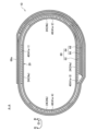
- FIG. 5 is a developed view of an example of the heating section 40 according to this embodiment.
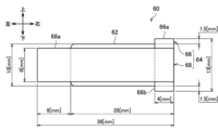
- FIG. 6 is a developed view of an example of the heat diffusion sheet 60 according to this embodiment. Note that the units of dimensions illustrated in FIGS. 5 and 6 are millimeters [mm]. It is assumed that the outer circumferential length of the accommodating portion 20 is 23.3 [mm].
- the height direction of the accommodating portion 20 (in other words, the direction in which the stick-shaped base material 150 is inserted and removed) is also referred to as the up-down direction.
- the direction toward the opening 22 of the accommodating portion 20 is defined as an upward direction, and the direction toward the bottom wall 26 is defined as a downward direction.
- the circumferential direction of the accommodating portion 20 is also referred to as the left-right direction.
- the clockwise direction is defined as the left direction
- the counterclockwise direction is defined as the right direction.
- the heater assembly 10 is one of the components that constitute the suction device 100.
- the heater assembly 10 is a component that is particularly involved in heating the stick-type base material 150.
- the heater assembly 10 includes a housing section 20, a heating section 40, and a heat diffusion sheet 60.
- the heater assembly 10 is constructed by wrapping and arranging the heating section 40 and the heat diffusion sheet 60 around the outer surface of the housing section 20.
- the housing section 20 is a bottomed cylindrical member that includes an opening 22, a side wall 24, and a bottom wall 26 that closes the end opposite to the opening 22.
- a hole (not shown) is provided in the bottom wall 26, and an air flow path 28 having a cylindrical shape is connected thereto.
- the stick-type base material 150 is inserted into the accommodating portion 20 through the opening 22 and is accommodated in the internal space 30 surrounded by the side wall 24 and the bottom wall 26 .
- the accommodating portion 20 is made of a material having a predetermined heat conductivity, such as SUS (Steel Use Stainless). This enables efficient heating of the stick-type base material 150.
- the side wall 24 of the accommodating portion 20 includes two planar portions 24a formed in a planar shape and two curved portions 24b formed in a curved manner.
- the shape of the accommodating portion 20 in a plane perpendicular to the vertical direction may be approximately elliptical.
- the two plane parts 24a may each form a straight line, and the two curved parts 24b may each form a semicircular arc.
- the distance between the inner surfaces of the two flat parts 24a is preferably smaller than the width of the stick-shaped base material 150. In that case, the accommodating part 20 can hold the stick-shaped base material 150 while pressing it with the two flat parts 24a.
- the heating section 40 includes a conductive track 41 and an electrically insulating base material 42.
- the conductive track 41 is a circuit made of a conductive material.
- the electrically insulating base material 42 is a film-like base material made of an insulating material.
- An example of the material having insulation properties is PI (Polyimide).
- the heating section 40 may be constructed by arranging a conductive track 41 on a membrane-like electrically insulating substrate 42 .
- the heating unit 40 may be a film heater configured by sandwiching a conductive track 41 between two electrically insulating base materials 42 configured as PI films.
- Other examples of materials having insulating properties include PET (Polyethylene terephthalate) and fluororesin.
- the conductive track 41 includes a heat generating portion 41a and a non-heat generating portion 41b.
- the heat generating portion 41a is a portion of the conductive track 41 that generates heat when a current is applied.
- the non-heat generating portion 41b is a portion of the conductive track 41 that does not generate heat or generates very little heat even when a current is applied. That is, the electrical resistance of the heat generating portion 41a is higher than the electrical resistance of the non-heat generating portion 41b.
- the heat generating portion 41a may be configured to be thin, and the non-heat generating portion 41b may be configured to be wide. Thereby, the magnitude relationship of the electrical resistance described above can be realized.
- the heat generating portion 41a may be made of, for example, SUS (steel use stainless).
- the non-heat generating portion 41b may be made of a material containing at least one of copper and nickel, for example.
- the non-heat generating portion 41b may be formed by plating SUS with copper and nickel.
- the thickness of SUS may be 30 ⁇ m
- the thickness of nickel may be 30 ⁇ m
- the thickness of copper may be 5 ⁇ m.
- the material constituting the conductive track 41 is not limited to the above example, but may be other materials such as aluminum.
- the heating unit 40 is placed in the housing unit 20 with a part of the outer surface of the housing unit 20 covered and the other part exposed.
- the heating section 40 may be formed in a shape having cutouts 49a and 49b in plan view. In that case, the heating section 40 covers the outer surface of the housing section 20 except for the cutouts 49a and 49b.
- the outer surface of the housing portion 20 is exposed at the cutouts 49a and 49b. According to this configuration, when the outer surface of the accommodating part 20 has irregularities, the heating part 40 comes into close contact with the outer surface of the accommodating part 20 while avoiding the irregularities on the outer surface of the accommodating part 20 by the cutouts 49a and 49b. becomes possible.
- the heating section 40 will float on the uneven portion of the outer surface of the housing section 20, and the temperature of the floating section will rise rapidly, potentially damaging the heating section 40.
- the heating section 40 comes into close contact with the outer surface of the housing section 20, so that it is possible to prevent the heating section 40 from being damaged.
- the electrically insulating base material 42 has cutouts 49a and 49b.
- the conductive track 41 is then placed on the electrically insulating base material 42, avoiding the cutouts 49a and 49b.
- the conductive track 41 is arranged on the electrically insulating base material 42 so as to go around the electrically insulating base material 42 from the lower end, bypassing the cutouts 49a and 49b, and return to the lower end again.
- the conductive track 41 is exposed from the electrically insulating base material 42 at the lower end of the heating section 40 and is electrically connected to the power supply section 111 .
- the conductive track 41 is formed in an M-shape with three folds in the heat generating portion 41a.
- heat generating portions 41a-1 to 41a-4 corresponding to four vertical bars arranged before and after the three folds forming the M-shape are arranged at equal intervals on the outer surface of the housing section 20. They may be spaced apart.
- the number of turns of the conductive track 41 is not limited to three, but may be any number greater than or equal to one.
- the thermal diffusion sheet 60 is constructed by laminating a graphite sheet 62 and a PI tape 64.
- the heat diffusion sheet 60 is an example of a heat diffusion layer formed in a film shape.
- the heat diffusion sheet 60 has a function of diffusing heat.
- the heat diffusion sheet 60 is arranged so as to be wrapped around the outside of the heating section 40, which is arranged around the outer surface of the housing section 20. As shown in FIGS. With this configuration, the heat of the heating section 40 can be diffused throughout the housing section 20. As a result, it becomes possible to efficiently heat the stick-shaped base material 150 housed in the housing section 20.
- the graphite sheet 62 is a sheet-like member made of graphite.
- the graphite sheet 62 is an example of a first layer whose thermal conductivity is greater than or equal to a first threshold value. It is desirable that the thermal conductivity of the graphite sheet 62 is higher than at least the thermal conductivity of the accommodating portion 20.
- An example of the first threshold value is 50 [W/(m ⁇ K)], and more preferably 100 [W/(m ⁇ K)]. Note that it is desirable that the thermal conductivity of the graphite sheet 62 in the plane direction is equal to or higher than the first threshold value, and the thermal conductivity of the graphite sheet 62 in the thickness direction is not particularly limited.
- the graphite sheet 62 has a thickness of 40 [um], a thermal conductivity in the plane direction of 1500 [W/(m ⁇ K)], and a thermal conductivity in the thickness direction of 5 [W/( m ⁇ K)]. According to this configuration, the graphite sheet 62 can efficiently transmit the heat of the heating section 40 to the entire area of the housing section 20.
- the PI tape 64 is a tape made of PI.
- the PI tape 64 is constructed by applying an adhesive to one surface of a film-like member made of PI.
- the PI tape 64 is an example of a second layer whose tensile strength is greater than or equal to the second threshold. It is desirable that the tensile strength of the PI tape 64 is at least higher than the tensile strength of the graphite sheet 62.
- An example of the second threshold value is 60 [MPa] under a normal temperature environment, and more preferably 120 [MPa]. Note that an example of the second threshold value relates to the tensile strength in the longitudinal direction when the PI tape 64 has a width of 25 mm. According to this configuration, the PI tape 64 can prevent the graphite sheet 62 from tearing during assembly.
- the PI tape 64 includes a vertically long PI tape 66 and a horizontally long PI tape 68.
- the vertically elongated PI tape 66 is an example of the first portion of the PI tape 64.
- the horizontally long PI tape 68 is an example of the second portion of the PI tape 64.
- the heat diffusion sheet 60 is constructed by having a graphite sheet 62 as the bottom layer, a vertically long PI tape 66 as the middle layer, and a horizontally long PI tape 68 as the top layer, which are superimposed and adhered.
- the vertically long PI tape 66 and the horizontally long PI tape 68 are stacked on top of each other with their adhesive surfaces facing toward the bottom layer.
- the graphite sheet 62, the vertically long PI tape 66, and the horizontally long PI tape 68 are stacked so that their right ends coincide and their vertical centers coincide. Note that when the heat diffusion sheet 60 is wound around the housing portion 20, the inner layer is the bottom layer, and the outer layer is the uppermost layer.
- the length of the graphite sheet 62 in the vertical direction is 10 mm, and the length in the horizontal direction is 28 mm.
- the length of the vertically long PI tape 66 in the vertical direction is 13 mm, and the length in the horizontal direction is 4 mm.
- the length of the horizontally long PI tape 68 in the vertical direction is 8 mm, and the length in the horizontal direction is 36 mm.
- the heat diffusion sheet 60 is arranged so as to be wrapped around the outside of the heating section 40 disposed on the outer surface of the storage section 20, with the graphite sheet 62 on the inside and the PI tape 64 on the outside. That is, the heating section 40, the graphite sheet 62, and the PI tape 64 are arranged around the outer surface of the housing section 20 in this order. According to this configuration, it becomes possible to bring the graphite sheet 62 into close contact with the heating section 40 or the housing section 20. As a result, it becomes possible to improve the heat diffusion effect from the heating section 40 to the housing section 20 via the graphite sheet 62.
- the graphite sheet 62 is formed longer than the outer circumferential length of the accommodating portion 20 in the left-right direction. Specifically, the length of the graphite sheet 62 in the left-right direction is 28 [mm], and the outer circumferential length of the accommodating portion 20 is 23.3 [mm]. As a result, as shown in FIG. 3, the graphite sheet 62 is wrapped around the outer surface of the accommodating portion 20 one or more times. According to this configuration, the graphite sheet 62 completely covers the outer periphery of the accommodating part 20, making it possible to diffuse the heat of the heating part 40 to the entire outer periphery of the accommodating part 20.
- the horizontally long PI tape 68 is formed to be longer than the outer circumferential length of the accommodating portion 20 in the left-right direction. Specifically, the length of the horizontally long PI tape 68 in the left-right direction is 36 [mm], and the outer circumferential length of the accommodating portion 20 is 23.3 [mm]. According to this configuration, the graphite sheet 62 can be more firmly fixed by wrapping the horizontally long PI tape 68 around the accommodating portion 20 one turn or more.
- the PI tape 64 (particularly the horizontally long PI tape 68) is formed longer than the graphite sheet 62 in the left-right direction. Specifically, the length of the horizontally long PI tape 68 in the left-right direction is 36 [mm], and the length of the graphite sheet 62 in the left-right direction is 28 [mm].
- the heat diffusion sheet 60 is formed by bonding the graphite sheet 62 and the PI tape 64 so that the PI tape 64 (in particular, the horizontally long PI tape 68) covers the entire graphite sheet 62 in the left and right direction.
- the heat diffusion sheet 60 is wound around the outer surface of the storage section 20 by rotating the storage section 20 while pressing the heat diffusion sheet 60 against the storage section 20 using a rubber roller or the like.
- the rubber roller when winding the heat diffusion sheet 60 around the storage portion 20, the rubber roller can be brought into contact only with the PI tape 64 and not with the graphite sheet 62. This makes it possible to reduce the force applied to the graphite sheet 62 and prevent the graphite sheet 62 from breaking.
- the horizontally long PI tape 68 is provided with a protruding portion 68a that protrudes from the graphite sheet 62 in the left-right direction.
- the protruding portion 68a is adhered to the PI tape 64 (particularly the horizontally long PI tape 68) that is wound one round inside the protruding portion 68a.
- the position of the graphite sheet 62 can be fixed by the horizontally long PI tape 68.
- the horizontally long PI tape 68 may be formed shorter than the graphite sheet 62 in the vertical direction.
- the length of the horizontally long PI tape 68 in the vertical direction is 8 [mm]
- the length of the graphite sheet 62 in the vertical direction is 10 [mm].
- the vertically long PI tape 66 is formed longer than the graphite sheet 62 in the vertical direction. Specifically, the length of the vertically long PI tape 66 in the vertical direction is 13 [mm], and the length of the graphite sheet 62 in the vertical direction is 10 [mm]. Therefore, both end portions 66a and 66b of the vertically long PI tape 66 in the vertical direction protrude from the graphite sheet 62 in the vertical direction. Specifically, both end portions 66a and 66b of the vertically long PI tape 66 protrude from the graphite sheet 62 by 1.5 mm in the vertical direction.
- both end portions 66 a and 66 b of the vertically long PI tape 66 that protrude from the graphite sheet 62 in the vertical direction are adhered to the heating section 40 . According to this configuration, it is possible to fix the heat diffusion sheet 60 to the heating section 40 and prevent misalignment between the heating section 40 and the heat diffusion sheet 60.
- the heating part 40 has blank areas 43a and 43b where the conductive track 41 is not arranged, which are vertically adjacent to the part where the heat generating part 41a is arranged.
- the blank areas 43a and 43b are areas consisting only of the electrically insulating base material 42.
- both end portions 66a and 66b in the vertical direction of the vertically long PI tape 66 are adhered to the blank areas 43a and 43b of the heating section 40.
- the heat diffusion sheet 60 can be more firmly fixed to the heating section 40.
- the size of the region of the heating unit 40 where the heat generating portion 41a is arranged is 20.75 [mm] in the left-right direction and 10 [mm] in the vertical direction.
- the blank areas 43a and 43b of the heating section 40 are configured to have positions and sizes corresponding to both end portions 66a and 66b of the vertically long PI tape 66.
- a blank area 43a having a size of 1.5 [mm] in the vertical direction and 6.1 [mm] in the horizontal direction is provided above the region of the heating unit 40 where the heat generating portion 41a is arranged. provided.
- a margin area 43b having a size of 1.5 [mm] in the vertical direction and 6.1 [mm] in the horizontal direction is provided below the region of the heating section 40 where the heat generating part 41a is arranged. .
- the blank area 43a and the blank area 43b of the heating unit 40 are provided so as to be separated by 10 mm in the vertical direction.
- the length from the top end to the bottom end of the margin areas 43a and 43b is 13 [mm], which is the same as the length in the vertical direction of the vertically long PI tape 66, and the length from the left end to the right end of the margin areas 43a and 43b is 13 [mm].
- the length is 6.1 mm, which is longer than the length of the tape 66 in the left-right direction.
- a graphite sheet 62 that also has a length of 10 [mm] in the vertical direction is wrapped around a region of the heating unit 40 that has a length of 10 [mm] in the vertical direction, where the heat generating portion 41a is arranged. becomes possible. According to this configuration, the portion of the heating section 40 where the heat generating portion 41a is arranged is completely covered with the graphite sheet 62, and the heat of the heating section 40 can be efficiently diffused.
- FIG. 7 is a flowchart illustrating an example of a method for manufacturing the heater assembly 10 according to this embodiment.
- FIG. 8 is a diagram schematically showing an example of a method for manufacturing the heater assembly 10 according to the present embodiment.
- the manufacturing method described below with reference to FIGS. 7 and 8 is executed by, for example, a machine tool.
- the machine tool includes a belt conveyor that conveys various parts, an arm that grips and operates various parts, a rotating machine that rotates the housing part 20, and a heating unit 40 and a heat diffusion sheet 60 on the outer surface of the rotating housing part 20. It may have a rubber roller or the like that adheres while pressing.
- the machine tool first generates the thermal diffusion sheet 60 by laminating and bonding the graphite sheet 62, the vertically long PI tape 66, and the horizontally long PI tape 68 (step S102).
- the machine tool adheres the thermal diffusion sheet 60 to the heating section 40 with the graphite sheet 62 on the inside (step S104).
- the machine tool adheres both vertically end portions 66a and 66b of the vertically long PI tape 66 to the blank areas 43a and 43b of the heating section 40.
- the machine tool places the bonded heating unit 40 and thermal diffusion sheet 60 around the outer surface of the storage unit 20, with the heating unit 40 on the inside (step S106). Specifically, first, as shown in FIG. 8, the machine tool attaches a portion of the bonded heating section 40 and heat diffusion sheet 60 that corresponds to the vertically long PI tape 66 to the flat section 24a of the accommodating section 20. Next, as shown in FIG. 8, the machine tool rotates the housing section 20 by 100 degrees to the left, and then by 640 degrees to the right. At this time, the machine tool rotates the housing section 20 while pressing the heating section 40 and the heat diffusion sheet 60 against the outer surface of the housing section 20 using a rubber roller. Thereby, the heating section 40 and the heat diffusion sheet 60 can be suitably adhered to the outer surface of the housing section 20.
- FIG. 9 is a diagram schematically showing an example of a cross section of the heater assembly 10 according to the first supplement.
- the heater assembly 10 may include a heat insulating part 70 and a heat shrink tube 80 in addition to the housing part 20, the heating part 40, and the heat diffusion sheet 60.
- the heater assembly 10 shown in FIG. 9 has a heating section 40 and a heat diffusion sheet 60 wrapped around the outer surface of the housing section 20, and a heat insulating section 70 and a heat shrink tube 80 wrapped around the outer side of the heating section 40 and a heat diffusion sheet 60. , configured.
- the heat insulating section 70 is constructed by laminating a heat insulating sheet 71 and a PI tape 72.
- the heat insulating sheet 71 is an example of a heat insulating layer whose thermal conductivity is less than the third threshold value. It is desirable that the thermal conductivity of the heat insulating sheet 71 is at least lower than that of the PI tape 64.
- An example of the third threshold is 1 [W/mK], and more preferably 0.5 [W/mK].
- the heat insulating sheet 71 is made of a glass material, a vacuum heat insulating material, an airgel heat insulating material, or the like.
- the heat insulating sheet 71 may be an airgel sheet made of an airgel heat insulating material and having a thermal conductivity of 0.02 [W/mK].
- the PI tape 72 is a tape made of PI.
- the PI tape 72 is constructed by applying an adhesive to one surface of a film-like member made of PI.
- the heat insulating section 70 is arranged so as to be wrapped further outside the heating section 40 and the heat diffusion sheet 60 that are wrapped around the outer surface of the housing section 20.
- the heat insulating section 70 is wound with the heat insulating sheet 71 on the inside and the PI tape 72 on the outside, with the adhesive surface of the PI tape 72 facing inward.
- the PI tape 72 is formed longer than the heat insulating sheet 71 in the left-right direction. Then, a protruding portion 72a of the PI tape 72 that protrudes from the heat insulating sheet 71 in the left-right direction is adhered to the PI tape 72 that is wound one round inside the protruding portion 72a of the PI tape 72.
- the PI tape 72 can fix the heat insulating sheet 71.
- the outer periphery of the heat diffusion sheet 60 can be completely covered by the heat insulating part 70.
- the heat shrink tube 80 is a tubular member that shrinks when heat is applied.
- the heating section 40 and the heat diffusion sheet 60 are wrapped around the outer surface of the housing section 20 and fixed to the housing section 20 with a heat shrink tube 80 while being covered by the heat insulating section 70 .
- the heat shrink tube 80 is made of a resin material.
- the heating unit 40 is attached to the outer surface of the accommodating portion 20 in a state where a part of the outer surface of the accommodating portion 20 is covered and the other part is exposed. Placed.
- the shape of the heating part 40 for realizing such a configuration is not formed in a shape having notches 49a and 49b in plan view.
- the heating section 40 may be formed in a T-shape in plan view.
- FIGS. 10 to 12 an example in which the heating section 40 is formed in a T-shape will be described with reference to FIGS. 10 to 12.
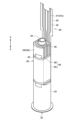
- FIG. 10 is a perspective view schematically showing an example of the heater assembly 10 according to the second supplement.
- FIG. 11 is a perspective view showing an example of the state before the heating unit 40 according to the second supplement is arranged on the outer surface of the housing unit 20.
- FIG. 12 is a perspective view showing an example of the state after the heating part 40 according to the second supplement is arranged on the outer surface of the housing part 20.
- the heater assembly 10 includes a housing section 20, a heating section 40, and a heat diffusion sheet 60.
- the heater assembly 10 is configured by arranging the heating section 40 and the heat diffusion sheet 60 on the outer surface of the housing section 20.
- the configuration of the accommodating portion 20 is as described in the above embodiment. However, as shown in FIGS. 10 to 12, the flat part 24a of the accommodating part 20 is formed only on a lower part of the side wall 24, and the side wall 24 above the flat part 24a may be curved. good.
- the heating section 40 has a T-shape in plan view before being bent.
- the T-shaped horizontal bar portion 44 of the heating section 40 is bent along the outer surface of the housing section 20 and arranged along the outer surface of the housing section 20 .
- the T-shaped vertical bar portion 45 of the heating portion 40 is bent in the opposite direction to the T-shaped horizontal bar portion 44, and is separated from the outer surface of the housing portion 20.
- the heating section 40 is provided with a hole 46. More specifically, a hole 46 is provided in the center of the T-shape before bending.
- the conductive track 41 starts from the end of the T-shaped vertical bar portion 45 of the heating unit 40, goes around the T-shaped horizontal bar portion 44 while bypassing the hole 46, and goes around the T-shaped horizontal bar portion 44 to the end of the T-shaped vertical bar portion 45. It is arranged so that it will come back to the department again.
- the heating unit 40 is arranged around the housing unit 20 with the air flow path 28 provided in the bottom wall 26 of the housing unit 20 passing through the hole 46 of the heating unit 40.
- the holes 46 of the heating section 40 circumscribe the air flow path 28 . With this configuration, it is possible to prevent the heating unit 40 from shifting.
- the heating section 40 is bent at a T-shaped horizontal bar section 44 and arranged along the bottom wall 26 and the flat section 24a of the accommodating section 20.
- the two flat parts 24a are provided at positions facing each other, and the T-shaped horizontal bar part 44 of the heating part 40 is arranged along each of these two facing flat parts 24a.
- the heating section 40 is fixed so as to sandwich the housing section 20 from the outside of the opposing flat section 24a. This makes it possible to prevent the heating unit 40 from shifting.
- the configuration of the heat diffusion sheet 60 is as described in the above embodiment.
- the heat diffusion sheet 60 is arranged so as to be wrapped around the housing section 20 in which the heating section 40 is arranged, with the graphite sheet 62 inside.
- the heat diffusion sheet 60 is arranged so as to be wrapped around the outer surface of the accommodating part 20 so as to cover the T-shaped horizontal bar part 44 of the heating part 40 arranged on the flat surface 24a of the accommodating part 20.
- a vertically long PI tape 66 is adhered to the curved portion 24b of the housing portion 20.
- the vertically long PI tape 66 may be adhered to the heating section 40 disposed on the flat section 24a of the housing section 20.
- the graphite sheet 62 made of graphite was cited as an example of the first layer making up the heat diffusion sheet 60, but the present invention is not limited to this example.
- the first layer constituting the heat diffusion sheet 60 may be composed of one or more materials selected from a group of materials including copper, graphite, aluminum, and the like.
- the PI tape 64 made of PI was cited as an example of the second layer making up the heat diffusion sheet 60, but the present invention is not limited to such an example.
- the second layer constituting the heat diffusion sheet 60 may be made of one or more materials selected from a group of materials including PI, silica, polyester, glass cloth, and the like.
- the heat diffusion sheet 60 is configured such that the bottom layer is a graphite sheet 62, the middle layer is a vertically long PI tape 66, and the top layer is a horizontally long PI tape 68, which are bonded in an overlapping state.
- the present invention is not limited to such examples.
- the adhesion order of the vertically long PI tape 66 and the horizontally long PI tape 68 may be reversed.
- each device described in this specification may be realized using software, hardware, or a combination of software and hardware.
- a program constituting the software is stored in advance, for example, in a recording medium (specifically, a computer-readable non-temporary storage medium) provided inside or outside each device.
- each program is read into the RAM when executed by a computer that controls each device described in this specification, and is executed by a processing circuit such as a CPU.
- the recording medium is, for example, a magnetic disk, an optical disk, a magneto-optical disk, a flash memory, or the like.
- the above computer program may be distributed, for example, via a network, without using a recording medium.
- the above-mentioned computer may be an application-specific integrated circuit such as an ASIC, a general-purpose processor that executes functions by loading a software program, or a computer on a server used for cloud computing. Furthermore, a series of processes performed by each device described in this specification may be distributed and processed by multiple computers.
- a cylindrical member having an opening into which an aerosol generating article containing an aerosol source can be inserted; a membrane-shaped heating section disposed on the outer surface of the cylindrical member; a thermal diffusion layer in which a first layer having a thermal conductivity equal to or higher than a first threshold value and a second layer having a tensile strength equal to or higher than a second threshold value are laminated; Equipped with The heat diffusion layer is arranged so as to wrap around the outside of the heating section disposed on the outer surface of the cylindrical member, with the first layer on the inside and the second layer on the outside. Aerosol generation system.
- the second layer is formed longer than the first layer in the circumferential direction of the cylindrical member,
- the heat diffusion layer is formed by adhering the first layer and the second layer so that the second layer covers the first layer over the entire circumferential direction of the cylindrical member.
- Ru The aerosol generation system according to (1) above.
- the second layer includes a first portion that is longer than the first layer in the height direction of the cylindrical member, Of the first portion of the second layer, both end portions protruding from the first layer in the height direction of the cylindrical member are bonded to the heating section.
- the heating section is a membrane-like electrically insulating base material; a conductive track disposed on the electrically insulating substrate; including; The both end portions of the first portion of the second layer are located at a height of the cylindrical member and a portion of the heating portion where a heating portion of the conductive track that generates heat when a current is applied is disposed. Adhering to a blank area adjacent in the width direction where the conductive track is not placed; The aerosol generation system according to (3) above.
- the second layer includes a second portion whose length in the circumferential direction of the cylindrical member is longer than the outer circumferential length of the cylindrical member, Among the second portions of the second layer, a protruding portion that protrudes from the first layer in the circumferential direction of the cylindrical member is a portion of the second layer that is wound one circumference inward from the protruding portion. glued to, The aerosol generation system according to any one of (1) to (4) above. (6) The second portion of the second layer is formed shorter than the first layer in the height direction of the cylindrical member. The aerosol generation system according to (5) above. (7) The first layer is formed to be longer than the outer circumferential length of the cylindrical member in the circumferential direction of the cylindrical member.
- the heating section is a membrane-like electrically insulating base material; a conductive track disposed on the electrically insulating substrate; including;
- the heating part is arranged on the outer surface of the cylindrical member, with a part of the outer surface of the cylindrical member covered and another part exposed.
- the heating part is formed in a T-shape or a shape having a notch in a plan view.
- the aerosol generation system includes: a heat insulating layer whose thermal conductivity is less than a third threshold; heat shrink tubing that shrinks when heated; Equipped with The heating part and the heat diffusion layer are wrapped around the outer surface of the cylindrical member and fixed to the cylindrical member with a heat shrink tube while being covered with the heat insulating layer.
- the aerosol generation system according to any one of (1) to (9) above.
- the first layer is formed of copper, graphite, or aluminum.
- the second layer is formed of PI (Polyimide).
- the cylindrical member is formed of SUS (steel use stainless).
- a heat diffusion layer in which a first layer having a thermal conductivity equal to or higher than a first threshold value and a second layer having a tensile strength equal to or higher than a second threshold value are laminated is formed into a film shape with the first layer inside. Adhering to the heating part of the arranging the bonded heating section and the thermal diffusion layer on the outer surface of a cylindrical member having an opening into which an aerosol generating article containing an aerosol source can be inserted, with the heating section inside;
- a method of manufacturing an aerosol generation system comprising:
- Suction device 111 Power supply section 112 Sensor section 113 Notification section 114 Storage section 115 Communication section 116 Control section 150 Stick type base material 151 Base material section 152 Sucking section 10 Heater assembly 20 Accommodation section 22 Opening 24 Side wall (24a: flat section, 24b : curved part) 26 Bottom wall 28 Air flow path 30 Internal space 40 Heating part 41 Conductive track (41a: heat generating part, 41b: non-heat generating part) 42 Electrical insulation base material 43a, 43b Margin area 60 Heat diffusion sheet 62 Graphite sheet 64 PI tape 66 Vertical PI tape (66a, 66b: both end portions) 68 Horizontal PI tape (68a: protruding part) 70 Heat insulation part 71 Heat insulation sheet 71 Heat insulation sheet 72 PI tape (72a: protruding part) 80 Heat shrink tube
Landscapes
- Resistance Heating (AREA)
Abstract
【課題】基材をより適切に加熱することが可能な仕組みを提供する。 【解決手段】エアロゾル源を含有したエアロゾル生成物品を挿入可能な開口を有する筒状部材と、前記筒状部材の外側面に配置される膜状の加熱部と、熱伝導率が第1の閾値以上である第1の層と引張強度が第2の閾値以上である第2の層とが積層された熱拡散層と、を備え、前記熱拡散層は、前記第1の層を内側とし前記第2の層を外側として、前記筒状部材の外側面に配置された前記加熱部の外側を覆うように巻き付けて配置される、エアロゾル生成システム。
Description
本発明は、エアロゾル生成システム、及びエアロゾル生成システムの製造方法に関する。
電子タバコ及びネブライザ等の、ユーザに吸引される物質を生成する吸引装置が広く普及している。例えば、吸引装置は、エアロゾルを生成するためのエアロゾル源、及び生成されたエアロゾルに香味成分を付与するための香味源等を含む基材を用いて、香味成分が付与されたエアロゾルを生成する。ユーザは、吸引装置により生成された、香味成分が付与されたエアロゾルを吸引することで、香味を味わうことができる。ユーザがエアロゾルを吸引する動作を、以下ではパフ又はパフ動作とも称する。
典型的には、基材を加熱することでエアロゾルが生成される。例えば、下記特許文献1では、基材を取り囲むように管状に巻かれた1枚のフィルムヒータにより、基材を加熱する技術が開示されている。
上記特許文献1に開示された技術では、基材を収容する筒状部材の外側にフィルムヒータが巻き付けられる。しかし、フィルムヒータを筒状部材に単に巻き付けただけでは、基材を適切に加熱することが困難になるおそれがあった。
そこで、本発明は、上記問題に鑑みてなされたものであり、本発明の目的とするところは、基材をより適切に加熱することが可能な仕組みを提供することにある。
上記課題を解決するために、本発明のある観点によれば、エアロゾル源を含有したエアロゾル生成物品を挿入可能な開口を有する筒状部材と、前記筒状部材の外側面に配置される膜状の加熱部と、熱伝導率が第1の閾値以上である第1の層と引張強度が第2の閾値以上である第2の層とが積層された熱拡散層と、を備え、前記熱拡散層は、前記第1の層を内側とし前記第2の層を外側として、前記筒状部材の外側面に配置された前記加熱部の外側を覆うように巻き付けて配置される、エアロゾル生成システムが提供される。
前記第2の層は、前記筒状部材の周方向において前記第1の層よりも長く形成され、前記熱拡散層は、前記第2の層が前記筒状部材の周方向の全体にわたって前記第1の層を覆うように、前記第1の層と前記第2の層とが接着されて形成されてもよい。
前記第2の層は、前記筒状部材の高さ方向において前記第1の層よりも長く形成される第1部分を含み、前記第2の層の前記第1部分のうち、前記筒状部材の高さ方向において前記第1の層から突出した両端部分は、前記加熱部に接着されてもよい。
前記加熱部は、膜状の電気絶縁基材と、前記電気絶縁基材上に配置された導電トラックと、を含み、前記第2の層の前記第1部分の前記両端部分は、前記加熱部のうち、前記導電トラックのうち電流が印可された場合に発熱する発熱部分が配置される部分と前記筒状部材の高さ方向において隣接する、前記導電トラックが配置されない余白領域に接着されてもよい。
前記第2の層は、前記筒状部材の周方向における長さが前記筒状部材の外周長よりも長く形成される第2部分を含み、前記第2の層の前記第2部分のうち、前記筒状部材の周方向において前記第1の層から突出する突出部分は、前記突出部分よりも1周内側に巻き付けられた前記第2の層に接着されてもよい。
前記第2の層の前記第2部分は、前記筒状部材の高さ方向において前記第1の層よりも短く形成されてもよい。
前記第1の層は、前記筒状部材の周方向において前記筒状部材の外周長よりも長く形成されてもよい。
前記加熱部は、膜状の電気絶縁基材と、前記電気絶縁基材上に配置された導電トラックと、を含み、前記加熱部は、前記筒状部材の外側面の一部を覆い他の一部を露出させた状態で、前記筒状部材の外側面に配置されてもよい。
前記加熱部は、平面視でT字状又は切り欠きを有する形状に形成されてもよい。
前記エアロゾル生成システムは、熱伝導率が第3の閾値未満である断熱層と、加熱された場合に収縮する熱収縮チューブと、を備え、前記加熱部及び前記熱拡散層は、前記筒状部材の外側面に巻き付けられ、前記断熱層により覆われた状態で、熱収縮チューブにより前記筒状部材に固定されてもよい。
前記第1の層は、銅、グラファイト、又はアルミニウムにより形成されてもよい。
前記第2の層は、PI(Polyimide)により形成されてもよい。
前記筒状部材は、SUS(steel use stainless)により形成されてもよい。
また、上記課題を解決するために、本発明の別の観点によれば、熱伝導率が第1の閾値以上である第1の層と引張強度が第2の閾値以上である第2の層とが積層された熱拡散層を、前記第1の層を内側として膜状の加熱部に接着することと、接着された前記加熱部と前記熱拡散層とを、前記加熱部を内側として、エアロゾル源を含有したエアロゾル生成物品を挿入可能な開口を有する筒状部材の外側面に配置することと、を含む、エアロゾル生成システムの製造方法が提供される。
以上説明したように本発明によれば、基材をより適切に加熱することが可能な仕組みが提供される。
以下に添付図面を参照しながら、本発明の好適な実施の形態について詳細に説明する。なお、本明細書及び図面において、実質的に同一の機能構成を有する構成要素については、同一の符号を付することにより重複説明を省略する。
<1.吸引装置の構成例>
吸引装置は、ユーザにより吸引される物質を生成する装置である。以下では、吸引装置により生成される物質が、エアロゾルであるものとして説明する。他に、吸引装置により生成される物質は、気体であってもよい。
吸引装置は、ユーザにより吸引される物質を生成する装置である。以下では、吸引装置により生成される物質が、エアロゾルであるものとして説明する。他に、吸引装置により生成される物質は、気体であってもよい。
図1は、吸引装置の構成例を模式的に示す模式図である。図1に示すように、本構成例に係る吸引装置100は、電源部111、センサ部112、通知部113、記憶部114、通信部115、制御部116、収容部20、加熱部40、及び断熱部70を含む。
電源部111は、電力を蓄積する。そして、電源部111は、制御部116による制御に基づいて、吸引装置100の各構成要素に電力を供給する。電源部111は、例えば、リチウムイオン二次電池等の充電式バッテリにより構成され得る。
センサ部112は、吸引装置100に関する各種情報を取得する。一例として、センサ部112は、コンデンサマイクロホン等の圧力センサ、流量センサ又は温度センサ等により構成され、ユーザによる吸引に伴う値を取得する。他の一例として、センサ部112は、ボタン又はスイッチ等の、ユーザからの情報の入力を受け付ける入力装置により構成される。
通知部113は、情報をユーザに通知する。通知部113は、例えば、発光する発光装置、画像を表示する表示装置、音を出力する音出力装置、又は振動する振動装置等により構成される。
記憶部114は、吸引装置100の動作のための各種情報を記憶する。記憶部114は、例えば、フラッシュメモリ等の不揮発性の記憶媒体により構成される。
通信部115は、有線又は無線の任意の通信規格に準拠した通信を行うことが可能な通信インタフェースである。かかる通信規格としては、例えば、Wi-Fi(登録商標)、Bluetooth(登録商標)、BLE(Bluetooth Low Energy(登録商標))、NFC(Near Field Communication)、又はLPWA(Low Power Wide Area)を用いる規格等が採用され得る。
制御部116は、演算処理装置及び制御装置として機能し、各種プログラムに従って吸引装置100内の動作全般を制御する。制御部116は、例えばCPU(Central Processing Unit)、又はマイクロプロセッサ等の電子回路によって実現される。
収容部20は、内部空間30を有し、内部空間30にスティック型基材150の一部を収容しながらスティック型基材150を保持する。収容部20は、開口22からスティック型基材150を挿入可能に構成される。とりわけ、収容部20は、内部空間30を外部に連通する開口22を有し、開口22から内部空間30に挿入されたスティック型基材150を収容する。例えば、収容部20は、開口22及び底壁26を両端とする筒状部材であり、柱状の内部空間30を画定する。収容部20には、内部空間30に空気を供給する空気流路が接続される。空気流路への空気の入口である空気流入孔は、例えば、吸引装置100の側面に配置される。空気流路から内部空間30への空気の出口である空気流出孔は、例えば、底壁26に配置される。
スティック型基材150は、基材部151、及び吸口部152を含む。基材部151は、エアロゾル源を含む。エアロゾル源は、たばこ由来又は非たばこ由来の香味成分を含む。吸引装置100がネブライザ等の医療用吸入器である場合、エアロゾル源は、薬剤を含んでもよい。エアロゾル源は、例えば、たばこ由来又は非たばこ由来の香味成分を含む、グリセリン及びプロピレングリコール等の多価アルコール、並びに水等の液体であってもよく、たばこ由来又は非たばこ由来の香味成分を含む固体であってもよい。スティック型基材150が収容部20に保持された状態において、基材部151の少なくとも一部は内部空間30に収容され、吸口部152の少なくとも一部は開口22から突出する。そして、開口22から突出した吸口部152をユーザが咥えて吸引すると、図示しない空気流路を経由して内部空間30に空気が流入し、基材部151から発生するエアロゾルと共にユーザの口内に到達する。
加熱部40は、エアロゾル源を加熱することで、エアロゾル源を霧化してエアロゾルを生成する。図1に示した例では、加熱部40は、膜状に構成され、収容部20の外周を覆うように配置される。そして、加熱部40が発熱すると、スティック型基材150の基材部151が外周から加熱され、エアロゾルが生成される。加熱部40は、電源部111から給電されると発熱する。一例として、ユーザが吸引を開始したこと、及び/又は所定の情報が入力されたことが、センサ部112により検出された場合に、給電されてもよい。そして、ユーザが吸引を終了したこと、及び/又は所定の情報が入力されたことが、センサ部112により検出された場合に、給電が停止されてもよい。
断熱部70は、加熱部40から他の構成要素への伝熱を防止する。例えば、断熱部70は、真空断熱材、又はエアロゲル断熱材等により構成される。
吸引装置100とスティック型基材150とは協働してユーザにより吸引されるエアロゾルを生成する。そのため、吸引装置100とスティック型基材150との組み合わせは、エアロゾル生成システムとして捉えられてもよい。スティック型基材150は、エアロゾル源を含有しエアロゾルを生成するエアロゾル生成物品の一例である。
<2.ヒータアッセンブリの詳細な構成>
以下、図2~図6を参照しながら、本実施形態に係る吸引装置100の物理的な構成について詳しく説明する。図2は、本実施形態に係るヒータアッセンブリ10の一例を模式的に示す斜視図である。図3は、矢視A-Aにおけるヒータアッセンブリ10の断面の一例を模式的に示す図である。図4は、本実施形態に係る収容部20の一例を模式的に示す斜視図である。図5は、本実施形態に係る加熱部40の一例を展開した展開図である。図6は、本実施形態に係る熱拡散シート60の一例を展開した展開図である。なお、図5及び図6に図示された寸法の単位はミリメートル[mm]である。収容部20の外周長は、23.3[mm]であるものとする。
以下、図2~図6を参照しながら、本実施形態に係る吸引装置100の物理的な構成について詳しく説明する。図2は、本実施形態に係るヒータアッセンブリ10の一例を模式的に示す斜視図である。図3は、矢視A-Aにおけるヒータアッセンブリ10の断面の一例を模式的に示す図である。図4は、本実施形態に係る収容部20の一例を模式的に示す斜視図である。図5は、本実施形態に係る加熱部40の一例を展開した展開図である。図6は、本実施形態に係る熱拡散シート60の一例を展開した展開図である。なお、図5及び図6に図示された寸法の単位はミリメートル[mm]である。収容部20の外周長は、23.3[mm]であるものとする。
これらの図において、収容部20の高さ方向(換言すると、スティック型基材150が挿抜される方向)を、上下方向とも称する。そして、収容部20のうち開口22側の方向を上方向とし、底壁26側の方向を下方向とする。また、収容部20の周方向を、左右方向とも称する。そして、開口22側から底壁26側を見たときの時計回りの方向を左方向とし、反時計回りの方向を右方向とする。
ヒータアッセンブリ10は、吸引装置100を構成する部品のひとつである。ヒータアッセンブリ10は、スティック型基材150の加熱に特に関与する部品である。図2に示すように、ヒータアッセンブリ10は、収容部20、加熱部40、及び熱拡散シート60を含む。とりわけ、図2及び図3に示すように、ヒータアッセンブリ10は、収容部20の外側面に、加熱部40及び熱拡散シート60を巻き付けて配置することで、構成される。
図4に示すように、収容部20は、開口22と、側壁24と、開口22と反対側の端部を塞ぐ底壁26と、を含む、有底の筒状部材である。底壁26には、図示しない孔が設けられ、筒状に構成された空気流路28が接続される。スティック型基材150は、開口22から収容部20に挿入され、側壁24及び底壁26により囲まれた内部空間30に収容される。収容部20は、例えばSUS(Steel Use Stainless)等の、所定の伝熱性を有する材料により構成される。これにより、スティック型基材150の効率的な加熱が可能になる。
図4に示すように、収容部20の側壁24は、平面状に形成される2つ平面部24aと、湾曲して形成される2つの湾曲部24bと、を含む。図3に示すように、上下方向に直交する面における収容部20の形状は、略楕円形であってよい。詳しくは、上下方向に直交する面において、2つの平面部24aはそれぞれ直線を形成し、2つの湾曲部24bはそれぞれ半円の円弧を形成してもよい。2つの平面部24aの内面間の距離は、スティック型基材150の幅よりも小さいことが好ましい。その場合、収容部20は、2つの平面部24aによりスティック型基材150を押圧しながら保持することが可能となる。
図5に示すように、加熱部40は、導電トラック41と電気絶縁基材42とを含む。導電トラック41は、導電性を有する材料により構成された回路である。電気絶縁基材42は、絶縁性を有する材料により構成された膜状の基材である。絶縁性を有する材料としては、PI(Polyimide)が挙げられる。加熱部40は、導電トラック41を膜状の電気絶縁基材42上に配置することで構成され得る。例えば、加熱部40は、導電トラック41をPIフィルムとして構成された2枚の電気絶縁基材42により挟み込むことで構成された、フィルムヒータであってよい。絶縁性を有する材料としては、他にもPET(Polyethylene terephthalate)又はフッ素樹脂等が挙げられる。
図5に示すように、導電トラック41は、発熱部分41aと非発熱部分41bとを含む。発熱部分41aは、導電トラック41のうち、電流が印可された場合に発熱する部分である。非発熱部分41bは、導電トラック41のうち、電流が印可されても発熱しない又は極微小に発熱する部分である。即ち、発熱部分41aの電気抵抗は、非発熱部分41bの電気抵抗よりも高い。一例として、発熱部分41aは細く構成され、非発熱部分41bは幅広に構成されてもよい。これにより、上述した電気抵抗の大小関係を実現することができる。また、発熱部分41aは、例えばSUS(steel use stainless)により構成されてよい。他方、非発熱部分41bは、例えば銅又はニッケルの少なくともいずれか1つを含む材料により構成されてよい。具体的には、非発熱部分41bは、SUSを銅及びニッケルでめっきすることで構成されてもよい。その際、例えば、SUSの厚みは30μmに、ニッケルの厚みは30μmに、銅の厚みは5μmに、構成されてよい。かかる構成によっても、上述した電気抵抗の大小関係を実現することができる上に、発熱部分41aの耐熱性を高くすることができる。もちろん、導電トラック41を構成する材料は上記の例に限定されず、アルミニウム等の他の材料であってよい。
加熱部40は、収容部20の外側面の一部を覆い他の一部を露出させた状態で、収容部20に配置される。とりわけ、図5に示すように、加熱部40は、平面視で切り欠き49a及び49bを有する形状に形成されてよい。その場合、加熱部40は、切り欠き49a及び49bを除いて収容部20の外側面を被覆する。他方、切り欠き49a及び49bにおいて収容部20の外側面が露出する。かかる構成によれば、収容部20の外側面に凹凸があった場合、収容部20の外側面の凹凸を切り欠き49a及び49bにより避けながら、加熱部40が収容部20の外側面に密着することが可能となる。切り欠き49a及び49bが無い場合、収容部20の外側面の凹凸部分において加熱部40が浮いてしまい、かかる浮いた部分の温度が急激に上昇して、加熱部40が損傷するおそれがある。この点、かかる構成によれば、加熱部40が収容部20の外側面に密着するので、加熱部40の損傷を防止することが可能となる。
図5に示すように、電気絶縁基材42は、切り欠き49a及び49bを有する。そして、導電トラック41は、切り欠き49a及び49bを避けて電気絶縁基材42上に配置される。詳しくは、導電トラック41は、下端から切り欠き49a及び49bを迂回しつつ電気絶縁基材42上を一巡して下端に再度戻ってくるように、電気絶縁基材42上に配置される。導電トラック41は、加熱部40の下端において電気絶縁基材42から露出し、電源部111に電気的に接続される。図5に示した例では、導電トラック41は、発熱部分41aにおいて、3つの折り返しを有するM字状に形成される。図3に示すように、M字を構成する3つの折り返しの前後に配置される4本の縦棒に対応する発熱部分41a-1~41a-4が、収容部20の外側面に等間隔に離隔して配置されていてもよい。もちろん、導電トラック41の折り返し数は3に限定されず、1以上の任意の数であってよい。
図6に示すように、熱拡散シート60は、グラファイトシート62とPIテープ64とが積層されて構成される。熱拡散シート60は、膜状に形成された熱拡散層の一例である。熱拡散シート60は、熱を拡散する機能を有する。図2及び図3に示すように、熱拡散シート60は、収容部20の外側面に巻き付けて配置された加熱部40の外側を覆うように巻き付けて配置される。かかる構成により、加熱部40の熱を収容部20の全体に拡散させることができる。その結果、収容部20に収容されたスティック型基材150を、効率的に加熱することが可能となる。
グラファイトシート62は、グラファイトにより構成されたシート状の部材である。グラファイトシート62は、熱伝導率が第1の閾値以上である第1の層の一例である。グラファイトシート62の熱伝導率は、少なくとも収容部20の熱伝導率よりも高いことが望ましい。第1の閾値の一例は、50[W/(m・K)]であり、さらに望ましくは、100[W/(m・K)]である。なお、グラファイトシート62の面方向の熱伝導率が第1の閾値以上であることが望ましく、グラファイトシート62の厚さ方向の熱伝導率は特に限定されない。厚さ方向の熱伝導は、電気絶縁基材42に律速されるためである。一例として、グラファイトシート62は、厚み40[um]に構成され、面方向の熱伝導率は1500[W/(m・K)]であり、厚さ方向の熱伝導率は5[W/(m・K)]であってよい。かかる構成によれば、グラファイトシート62は、加熱部40の熱を収容部20の全域に効率よく伝達することが可能となる。
PIテープ64は、PIにより構成されたテープである。PIテープ64は、PIにより構成された膜状の部材の一面に、接着剤を塗布することで構成される。PIテープ64は、引張強度が第2の閾値以上である第2の層の一例である。PIテープ64の引張強度は、少なくともグラファイトシート62の引張強度よりも高いことが望ましい。第2の閾値の一例は、常温環境下で60[MPa]であり、さらに望ましくは、120[MPa]である。なお、かかる第2の閾値の一例は、PIテープ64が25mm幅である場合の長さ方向の引張強度に関する。かかる構成によれば、PIテープ64は、組み立て時のグラファイトシート62の破れを防止することが可能となる。
図6に示すように、PIテープ64は、縦長PIテープ66及び横長PIテープ68を含む。縦長PIテープ66は、PIテープ64の第1部分の一例である。横長PIテープ68は、PIテープ64の第2部分の一例である。
熱拡散シート60は、最下層をグラファイトシート62とし、中層を縦長PIテープ66とし、最上層を横長PIテープ68として、重ね合わされた状態で接着されることで、構成される。縦長PIテープ66及び横長PIテープ68は、接着面を最下層に向けた状態で、重ね合わされる。とりわけ、グラファイトシート62、縦長PIテープ66、及び横長PIテープ68は、右端が一致し、且つ上下方向の中心が一致するようにして重ね合わされる。なお、ここでは、熱拡散シート60を収容部20に巻き付ける際に内側となる層を最下層とし、外側となる層を最上層としている。
図6に示した例では、グラファイトシート62の上下方向における長さは10mmであり、左右方向における長さは28mmである。縦長PIテープ66の上下方向における長さは13mmであり、左右方向における長さは4mmである。横長PIテープ68の上下方向における長さは8mmであり、左右方向における長さは36mmである。
熱拡散シート60は、グラファイトシート62を内側としPIテープ64を外側として、収容部20の外側面に配置された加熱部40の外側を覆うように巻き付けて配置される。即ち、収容部20の外側面に、加熱部40、グラファイトシート62、及びPIテープ64が、この順番に巻き付けて配置される。かかる構成によれば、グラファイトシート62を加熱部40又は収容部20に密着させることが可能となる。その結果、グラファイトシート62を介した加熱部40から収容部20への熱拡散効果を向上させることが可能となる。また、かかる構成によれば、加熱部40又は収容部20に密着したグラファイトシート62を、外側からPIテープ64により保護することが可能となる。その結果、PIテープ64によるグラファイトシート62の破れ防止効果を向上させることが可能となる。
グラファイトシート62は、左右方向において収容部20の外周長よりも長く形成される。具体的には、グラファイトシート62の左右方向の長さは28[mm]であり、収容部20の外周長は23.3[mm]である。その結果、図3に示すように、収容部20の外側面に、グラファイトシート62が1周以上巻き付けられる。かかる構成によれば、グラファイトシート62により収容部20の外周を余すことなく覆い、加熱部40の熱を収容部20の外周全体に拡散させることが可能となる。
横長PIテープ68は、左右方向において収容部20の外周長よりも長く形成される。具体的には、横長PIテープ68の左右方向の長さは36[mm]であり、収容部20の外周長は23.3[mm]である。かかる構成によれば、横長PIテープ68を収容部20に1周以上巻き付けて、グラファイトシート62をより強固に固定することが可能となる。
図6に示すように、PIテープ64(とりわけ、横長PIテープ68)は、左右方向においてグラファイトシート62よりも長く形成される。具体的には、横長PIテープ68の左右方向の長さは36[mm]であり、グラファイトシート62の左右方向の長さは28[mm]である。そして、熱拡散シート60は、PIテープ64(とりわけ、横長PIテープ68)が左右方向の全体にわたってグラファイトシート62を覆うように、グラファイトシート62とPIテープ64とを接着することで形成される。後述するように、ゴムローラー等で熱拡散シート60を収容部20に押し当てた状態で収容部20を回転させることで、熱拡散シート60が収容部20の外側面に巻き付けられる。この点、かかる構成によれば、熱拡散シート60を収容部20に巻き付ける際に、ゴムローラーをPIテープ64にのみ接触させ、グラファイトシート62に非接触にすることができる。これにより、グラファイトシート62にかかる力を緩和して、グラファイトシート62の破断を防止することが可能となる。
図6に示すように、横長PIテープ68には、左右方向においてグラファイトシート62から突出する突出部分68aが設けられる。そして、図3に示すように、かかる突出部分68aは、当該突出部分68aよりも1周内側に巻き付けられたPIテープ64(とりわけ、横長PIテープ68)に接着される。かかる構成によれば、グラファイトシート62の位置を、横長PIテープ68により固定することができる。その結果、グラファイトシート62に余計な力が加わってグラファイトシート62が破断するような事態を防止することが可能となる。
さらに、図6に示すように、横長PIテープ68は、上下方向においてグラファイトシート62よりも短く形成されてよい。具体的には、横長PIテープ68の上下方向の長さは8[mm]であり、グラファイトシート62の上下方向の長さは10[mm]である。かかる構成によれば、横長PIテープ68が、上下方向においてグラファイトシート62から突出して、加熱部40又は収容部20に直接接着するような事態が防止される。これにより、グラファイトシート62を、遊びを持たせつつ固定することができる。その結果、グラファイトシート62に余計な力が加わってグラファイトシート62が破断するような事態を防止することが可能となる。
図6に示すように、縦長PIテープ66は、上下方向においてグラファイトシート62よりも長く形成される。具体的には、縦長PIテープ66の上下方向の長さは13[mm]であり、グラファイトシート62の上下方向の長さは10[mm]である。そのため、縦長PIテープ66の上下方向の両端部分66a及び66bは、上下方向においてグラファイトシート62から突出することとなる。具体的には、縦長PIテープ66の両端部分66a及び66bは、上下方向においてグラファイトシート62から1.5[mm]突出している。そして、縦長PIテープ66のうち、上下方向においてグラファイトシート62から突出した両端部分66a及び66bは、加熱部40に接着される。かかる構成によれば、熱拡散シート60を加熱部40に固定して、加熱部40と熱拡散シート60との間の位置ずれを防止することが可能となる。
ここで、図5に示すように、加熱部40は、発熱部分41aが配置される部分と上下方向において隣接する、導電トラック41が配置されない余白領域43a及び43bを有する。余白領域43a及び43bは、電気絶縁基材42のみから成る領域である。そして、縦長PIテープ66の上下方向の両端部分66a及び66bは、加熱部40の余白領域43a及び43bに接着される。このように、熱拡散シート60を接着するための余白領域43a及び43bを加熱部40に予め設けておくことで、熱拡散シート60をより強固に加熱部40に固定することが可能となる。
具体的には、図5に示すように、加熱部40のうち発熱部分41aが配置される領域の大きさは、左右方向で20.75[mm]、上下方向で10[mm]である。そして、加熱部40の余白領域43a及び43bは、縦長PIテープ66の両端部分66a及び66bに対応する位置及び大きさに構成される。具体的には、加熱部40のうち発熱部分41aが配置される領域の上側に、上下方向において1.5[mm]、左右方向において6.1[mm]の大きさを有する余白領域43aが設けられる。他方、加熱部40のうち発熱部分41aが配置される領域の下側に、上下方向において1.5[mm]、左右方向において6.1[mm]の大きさを有する余白領域43bが設けられる。そして、加熱部40の余白領域43a及び余白領域43bは、上下方向において10[mm]離隔するよう、設けられる。その結果、余白領域43a及び43bの上端から下端までの長さが縦長PIテープ66の上下方向の長さと同じ13[mm]となり、余白領域43a及び43bの左端から右端までの長さが縦長PIテープ66の左右方向の長さよりも長い6.1[mm]となる。これにより、余白領域43a及び43bに、縦長PIテープ66の上下方向の両端部分66a及び66bを余すことなく接着することが可能となる。さらには、加熱部40のうち発熱部分41aが配置される、上下方向に10[mm]の長さを有する領域に、同じく上下方向に10[mm]の長さを有するグラファイトシート62を、巻き付けることが可能となる。かかる構成によれば、加熱部40のうち発熱部分41aが配置される部分を、グラファイトシート62により余すことなく被覆し、加熱部40の熱を効率よく拡散させることが可能となる。
<3.ヒータアッセンブリの製造方法>
以下、図7及び図8を参照しながら、ヒータアッセンブリ10の製造方法の一例を説明する。図7は、本実施形態に係るヒータアッセンブリ10の製造方法の一例を示すフローチャートである。図8は、本実施形態に係るヒータアッセンブリ10の製造方法の一例を模式的に示す図である。
以下、図7及び図8を参照しながら、ヒータアッセンブリ10の製造方法の一例を説明する。図7は、本実施形態に係るヒータアッセンブリ10の製造方法の一例を示すフローチャートである。図8は、本実施形態に係るヒータアッセンブリ10の製造方法の一例を模式的に示す図である。
図7及び図8を参照しながら以下に説明する製造方法は、例えば、工作機械により実行される。工作機械は、各種部品を搬送するベルトコンベア、各種部品を把持して操作するアーム、収容部20を回転させる回転機、並びに回転する収容部20の外側面に加熱部40及び熱拡散シート60を押し当てながら接着するゴムローラー等を有し得る。
図7に示すように、まず、工作機械は、グラファイトシート62、縦長PIテープ66、及び横長PIテープ68を積層して接着することで、熱拡散シート60を生成する(ステップS102)。
次いで、工作機械は、熱拡散シート60を、グラファイトシート62を内側として加熱部40に接着する(ステップS104)。とりわけ、工作機械は、縦長PIテープ66の上下方向の両端部分66a及び66bを、加熱部40の余白領域43a及び43bに接着する。
次に、工作機械は、接着された加熱部40と熱拡散シート60とを、加熱部40を内側として、収容部20の外側面に巻き付けて配置する(ステップS106)。詳しくは、まず、図8に示すように、工作機械は、接着した加熱部40及び熱拡散シート60のうち、縦長PIテープ66に対応する部分を収容部20の平面部24aに貼り付ける。次いで、図8に示すように、工作機械は、収容部20を左に100°回転させ、その後右に640°回転させる。その際、工作機械は、収容部20の外側面に加熱部40及び熱拡散シート60をゴムローラーにより押し当てながら、収容部20を回転させる。これにより、収容部20の外側面に加熱部40及び熱拡散シート60を好適に接着させることができる。
<4.補足>
以上、添付図面を参照しながら本発明の好適な実施形態について詳細に説明したが、本発明はかかる例に限定されない。本発明の属する技術の分野における通常の知識を有する者であれば、請求の範囲に記載された技術的思想の範疇内において、各種の変更例または修正例に想到し得ることは明らかであり、これらについても、当然に本発明の技術的範囲に属するものと了解される。
以上、添付図面を参照しながら本発明の好適な実施形態について詳細に説明したが、本発明はかかる例に限定されない。本発明の属する技術の分野における通常の知識を有する者であれば、請求の範囲に記載された技術的思想の範疇内において、各種の変更例または修正例に想到し得ることは明らかであり、これらについても、当然に本発明の技術的範囲に属するものと了解される。
(1)第1の補足
上記実施形態では、ヒータアッセンブリ10の構成から断熱部70を省略して説明したが、ヒータアッセンブリ10は断熱部70を含み得る。断熱部70を含むヒータアッセンブリ10について、図9を参照しながら説明する。図9は、第1の補足に係るヒータアッセンブリ10の断面の一例を模式的に示す図である。
上記実施形態では、ヒータアッセンブリ10の構成から断熱部70を省略して説明したが、ヒータアッセンブリ10は断熱部70を含み得る。断熱部70を含むヒータアッセンブリ10について、図9を参照しながら説明する。図9は、第1の補足に係るヒータアッセンブリ10の断面の一例を模式的に示す図である。
図9に示すように、ヒータアッセンブリ10は、収容部20、加熱部40、及び熱拡散シート60に加えて、断熱部70及び熱収縮チューブ80を含んでいてもよい。図9に示すヒータアッセンブリ10は、収容部20の外側面に、加熱部40及び熱拡散シート60を巻き付けて配置し、さらにその外側に断熱部70及び熱収縮チューブ80を巻き付けて配置することで、構成される。
断熱部70は、断熱シート71とPIテープ72とが積層されて構成される。断熱シート71は、熱伝導率が第3の閾値未満である断熱層の一例である。断熱シート71の熱伝導率は、少なくともPIテープ64より低いことが望ましい。第3の閾値の一例は、1[W/mK]であり、さらに望ましくは、0.5[W/mK]である。例えば、断熱シート71は、ガラス材料、真空断熱材、又はエアロゲル断熱材等により構成される。一例として、断熱シート71は、エアロゲル断熱材により構成された、熱伝導率が0.02[W/mK]であるエアロゲルシートであってよい。PIテープ72は、PIにより構成されたテープである。PIテープ72は、PIにより構成された膜状の部材の一面に、接着剤を塗布することで構成される。
図9に示すように、断熱部70は、収容部20の外側面に巻き付けられた加熱部40及び熱拡散シート60のさらに外側に巻き付けて配置される。とりわけ、断熱部70は、断熱シート71を内側としPIテープ72を外側とし、且つPIテープ72の接着面を内側に向けて、巻き付けられる。PIテープ72は、左右方向に断熱シート71よりも長く形成される。そして、PIテープ72のうち、左右方向において断熱シート71から突出する突出部分72aは、PIテープ72のうち当該突出部分72aよりも1周内側に巻き付けられたPIテープ72に接着される。これにより、PIテープ72は、断熱シート71を固定することができる。かかる構成によれば、断熱部70により熱拡散シート60の外周を余すことなく覆うことができる。その結果、熱拡散シート60により拡散された加熱部40からの熱が、断熱部70よりも外側に拡散することを防止することが可能となる。
熱収縮チューブ80は、熱を加えると収縮する、管状の部材である。加熱部40及び熱拡散シート60は、収容部20の外側面に巻き付けられ、断熱部70により覆われた状態で、熱収縮チューブ80により収容部20に固定される。例えば、熱収縮チューブ80は、樹脂材料により構成される。収容部20に、加熱部40、熱拡散シート60、断熱部70、及び熱収縮チューブ80を順に巻き付けた状態で、熱収縮チューブ80を加熱することで、これらの構成要素を容易に固定することが可能となる。
(2)第2の補足
上記実施形態において説明したように、加熱部40は、収容部20の外側面の一部を覆い他の一部を露出させた状態で、収容部20の外側面に配置される。ただし、かかる構成を実現するための加熱部40の形状は、平面視で切り欠き49a及び49bを有する形状に形成されない。他の一例として、加熱部40は、平面視でT字状に形成されてもよい。以下、加熱部40がT字状に形成される例について、図10~図12を参照しながら説明する。
上記実施形態において説明したように、加熱部40は、収容部20の外側面の一部を覆い他の一部を露出させた状態で、収容部20の外側面に配置される。ただし、かかる構成を実現するための加熱部40の形状は、平面視で切り欠き49a及び49bを有する形状に形成されない。他の一例として、加熱部40は、平面視でT字状に形成されてもよい。以下、加熱部40がT字状に形成される例について、図10~図12を参照しながら説明する。
図10は、第2の補足に係るヒータアッセンブリ10の一例を模式的に示す斜視図である。図11は、第2の補足に係る加熱部40を収容部20の外側面に配置する前の様子の一例を示す斜視図である。図12は、第2の補足に係る加熱部40を収容部20の外側面に配置した後の様子の一例を示す斜視図である。
図10に示すように、ヒータアッセンブリ10は、収容部20、加熱部40、及び熱拡散シート60を含む。とりわけ、ヒータアッセンブリ10は、収容部20の外側面に、加熱部40及び熱拡散シート60を配置することで、構成される。
収容部20の構成は、上記実施形態において説明した通りである。ただし、図10~図12に示すように、収容部20の平面部24aは、側壁24のうち下側の一部にのみ形成され、平面部24aよりも上側の側壁24は湾曲していてもよい。
図11に示すように、加熱部40は、折り曲げ前の状態において平面視でT字型を構成する。そして、図12に示すように、加熱部40のうちT字の横棒部分44が、収容部20の外面に沿うように折り曲げられ、収容部20の外面に沿って配置される。他方、図12に示すように、加熱部40のうちT字の縦棒部分45は、T字の横棒部分44とは逆方向に折り曲げられ、収容部20の外面から離隔される。
図11に示すように、加熱部40には、孔46が設けられる。より詳しくは、折り曲げ前の状態におけるT字の中央部分に、孔46が設けられる。そして、導電トラック41は、加熱部40のうちT字の縦棒部分45の端部から、孔46を迂回しつつT字の横棒部分44を一巡してT字の縦棒部分45の端部に再度戻ってくるように配置される。
図12に示すように、加熱部40は、収容部20の底壁26に設けられた空気流路28が加熱部40の孔46を通過した状態で、収容部20の周囲に配置される。とりわけ、加熱部40の孔46は、空気流路28に外接する。かかる構成により、加熱部40の位置ずれを防止することが可能となる。
さらに、図12に示すように、加熱部40は、T字の横棒部分44において折り曲げられ、収容部20の底壁26及び平面部24aに沿って配置される。ここで、2つの平面部24aは、互いに対向する位置に設けられており、加熱部40のT字の横棒部分44が、これら対向する2つの平面部24aの各々に沿って配置される。かかる構成により、加熱部40は、収容部20を対向する平面部24aの外側から挟持するようにして固定される。これにより、加熱部40の位置ずれを防止することが可能となる。
熱拡散シート60の構成は、上記実施形態において説明した通りである。図10に示すように、熱拡散シート60は、グラファイトシート62を内側として、加熱部40が配置された収容部20に巻き付けて配置される。とりわけ、熱拡散シート60は、収容部20の平面部24aに配置された加熱部40のT字の横棒部分44を覆うように、収容部20の外側面に巻き付けて配置される。図10に示した例では、縦長PIテープ66が収容部20の湾曲部24bに接着されている。かかる配置は一例であり、縦長PIテープ66は、収容部20の平面部24aに配置された加熱部40に接着されてもよい。
(3)その他
上記実施形態では、熱拡散シート60を構成する第1の層の一例として、グラファイトにより構成されたグラファイトシート62を挙げたが、本発明はかかる例に限定されない。熱拡散シート60を構成する第1の層は、銅、グラファイト、又はアルミニウム等を含む材料群から選択された1つ以上の材料により構成されてよい。
上記実施形態では、熱拡散シート60を構成する第1の層の一例として、グラファイトにより構成されたグラファイトシート62を挙げたが、本発明はかかる例に限定されない。熱拡散シート60を構成する第1の層は、銅、グラファイト、又はアルミニウム等を含む材料群から選択された1つ以上の材料により構成されてよい。
上記実施形態では、熱拡散シート60を構成する第2の層の一例として、PIにより構成されたPIテープ64を挙げたが、本発明はかかる例に限定されない。熱拡散シート60を構成する第2の層は、PI、シリカ、ポリエステル又はガラスクロス等を含む材料群から選択された1つ以上の材料により構成されてよい。
上記実施形態では、熱拡散シート60が、最下層をグラファイトシート62とし、中層を縦長PIテープ66とし、最上層を横長PIテープ68として、重ね合わされた状態で接着されることで、構成される例を説明したが、本発明はかかる例に限定されない。縦長PIテープ66と横長PIテープ68の接着順序は逆であってもよい。
なお、本明細書において説明した各装置による一連の処理は、ソフトウェア、ハードウェア、及びソフトウェアとハードウェアとの組合せのいずれを用いて実現されてもよい。ソフトウェアを構成するプログラムは、例えば、各装置の内部又は外部に設けられる記録媒体(詳しくは、コンピュータにより読み取り可能な非一時的な記憶媒体)に予め格納される。そして、各プログラムは、例えば、本明細書において説明した各装置を制御するコンピュータによる実行時にRAMに読み込まれ、CPUなどの処理回路により実行される。上記記録媒体は、例えば、磁気ディスク、光ディスク、光磁気ディスク、フラッシュメモリ等である。また、上記のコンピュータプログラムは、記録媒体を用いずに、例えばネットワークを介して配信されてもよい。また、上記のコンピュータは、ASICのような特定用途向け集積回路、ソフトウエアプログラムを読み込むことで機能を実行する汎用プロセッサ、又はクラウドコンピューティングに使用されるサーバ上のコンピュータ等であってよい。また、本明細書において説明した各装置による一連の処理は、複数のコンピュータにより分散して処理されてもよい。
また、本明細書においてフローチャート及びシーケンス図を用いて説明した処理は、必ずしも図示された順序で実行されなくてもよい。いくつかの処理ステップは、並列的に実行されてもよい。また、追加的な処理ステップが採用されてもよく、一部の処理ステップが省略されてもよい。
なお、以下のような構成も本発明の技術的範囲に属する。
(1)
エアロゾル源を含有したエアロゾル生成物品を挿入可能な開口を有する筒状部材と、
前記筒状部材の外側面に配置される膜状の加熱部と、
熱伝導率が第1の閾値以上である第1の層と引張強度が第2の閾値以上である第2の層とが積層された熱拡散層と、
を備え、
前記熱拡散層は、前記第1の層を内側とし前記第2の層を外側として、前記筒状部材の外側面に配置された前記加熱部の外側を覆うように巻き付けて配置される、
エアロゾル生成システム。
(2)
前記第2の層は、前記筒状部材の周方向において前記第1の層よりも長く形成され、
前記熱拡散層は、前記第2の層が前記筒状部材の周方向の全体にわたって前記第1の層を覆うように、前記第1の層と前記第2の層とが接着されて形成される、
前記(1)に記載のエアロゾル生成システム。
(3)
前記第2の層は、前記筒状部材の高さ方向において前記第1の層よりも長く形成される第1部分を含み、
前記第2の層の前記第1部分のうち、前記筒状部材の高さ方向において前記第1の層から突出した両端部分は、前記加熱部に接着される、
前記(1)又は(2)に記載のエアロゾル生成システム。
(4)
前記加熱部は、
膜状の電気絶縁基材と、
前記電気絶縁基材上に配置された導電トラックと、
を含み、
前記第2の層の前記第1部分の前記両端部分は、前記加熱部のうち、前記導電トラックのうち電流が印可された場合に発熱する発熱部分が配置される部分と前記筒状部材の高さ方向において隣接する、前記導電トラックが配置されない余白領域に接着される、
前記(3)に記載のエアロゾル生成システム。
(5)
前記第2の層は、前記筒状部材の周方向における長さが前記筒状部材の外周長よりも長く形成される第2部分を含み、
前記第2の層の前記第2部分のうち、前記筒状部材の周方向において前記第1の層から突出する突出部分は、前記突出部分よりも1周内側に巻き付けられた前記第2の層に接着される、
前記(1)~(4)のいずれか一項に記載のエアロゾル生成システム。
(6)
前記第2の層の前記第2部分は、前記筒状部材の高さ方向において前記第1の層よりも短く形成される、
前記(5)に記載のエアロゾル生成システム。
(7)
前記第1の層は、前記筒状部材の周方向において前記筒状部材の外周長よりも長く形成される、
前記(1)~(6)のいずれか一項に記載のエアロゾル生成システム。
(8)
前記加熱部は、
膜状の電気絶縁基材と、
前記電気絶縁基材上に配置された導電トラックと、
を含み、
前記加熱部は、前記筒状部材の外側面の一部を覆い他の一部を露出させた状態で、前記筒状部材の外側面に配置される、
前記(1)~(7)のいずれか一項に記載のエアロゾル生成システム。
(9)
前記加熱部は、平面視でT字状又は切り欠きを有する形状に形成される、
前記(8)に記載のエアロゾル生成システム。
(10)
前記エアロゾル生成システムは、
熱伝導率が第3の閾値未満である断熱層と、
加熱された場合に収縮する熱収縮チューブと、
を備え、
前記加熱部及び前記熱拡散層は、前記筒状部材の外側面に巻き付けられ、前記断熱層により覆われた状態で、熱収縮チューブにより前記筒状部材に固定される、
前記(1)~(9)のいずれか一項に記載のエアロゾル生成システム。
(11)
前記第1の層は、銅、グラファイト、又はアルミニウムにより形成される、
前記(1)~(10)のいずれか一項に記載のエアロゾル生成システム。
(12)
前記第2の層は、PI(Polyimide)により形成される、
前記(1)~(11)のいずれか一項に記載のエアロゾル生成システム。
(13)
前記筒状部材は、SUS(steel use stainless)により形成される、
前記(1)~(12)のいずれか一項に記載のエアロゾル生成システム。
(14)
熱伝導率が第1の閾値以上である第1の層と引張強度が第2の閾値以上である第2の層とが積層された熱拡散層を、前記第1の層を内側として膜状の加熱部に接着することと、
接着された前記加熱部と前記熱拡散層とを、前記加熱部を内側として、エアロゾル源を含有したエアロゾル生成物品を挿入可能な開口を有する筒状部材の外側面に配置することと、
を含む、エアロゾル生成システムの製造方法。
100 吸引装置
111 電源部
112 センサ部
113 通知部
114 記憶部
115 通信部
116 制御部
150 スティック型基材
151 基材部
152 吸口部
10 ヒータアッセンブリ
20 収容部
22 開口
24 側壁(24a:平面部、24b:湾曲部)
26 底壁
28 空気流路
30 内部空間
40 加熱部
41 導電トラック(41a:発熱部分、41b:非発熱部分)
42 電気絶縁基材
43a、43b 余白領域
60 熱拡散シート
62 グラファイトシート
64 PIテープ
66 縦長PIテープ(66a、66b:両端部分)
68 横長PIテープ(68a:突出部分)
70 断熱部
71 断熱シート
71 断熱シート
72 PIテープ(72a:突出部分)
80 熱収縮チューブ
Claims (14)
- エアロゾル源を含有したエアロゾル生成物品を挿入可能な開口を有する筒状部材と、
前記筒状部材の外側面に配置される膜状の加熱部と、
熱伝導率が第1の閾値以上である第1の層と引張強度が第2の閾値以上である第2の層とが積層された熱拡散層と、
を備え、
前記熱拡散層は、前記第1の層を内側とし前記第2の層を外側として、前記筒状部材の外側面に配置された前記加熱部の外側を覆うように巻き付けて配置される、
エアロゾル生成システム。 - 前記第2の層は、前記筒状部材の周方向において前記第1の層よりも長く形成され、
前記熱拡散層は、前記第2の層が前記筒状部材の周方向の全体にわたって前記第1の層を覆うように、前記第1の層と前記第2の層とが接着されて形成される、
請求項1に記載のエアロゾル生成システム。 - 前記第2の層は、前記筒状部材の高さ方向において前記第1の層よりも長く形成される第1部分を含み、
前記第2の層の前記第1部分のうち、前記筒状部材の高さ方向において前記第1の層から突出した両端部分は、前記加熱部に接着される、
請求項1又は2に記載のエアロゾル生成システム。 - 前記加熱部は、
膜状の電気絶縁基材と、
前記電気絶縁基材上に配置された導電トラックと、
を含み、
前記第2の層の前記第1部分の前記両端部分は、前記加熱部のうち、前記導電トラックのうち電流が印可された場合に発熱する発熱部分が配置される部分と前記筒状部材の高さ方向において隣接する、前記導電トラックが配置されない余白領域に接着される、
請求項3に記載のエアロゾル生成システム。 - 前記第2の層は、前記筒状部材の周方向における長さが前記筒状部材の外周長よりも長く形成される第2部分を含み、
前記第2の層の前記第2部分のうち、前記筒状部材の周方向において前記第1の層から突出する突出部分は、前記突出部分よりも1周内側に巻き付けられた前記第2の層に接着される、
請求項1~4のいずれか一項に記載のエアロゾル生成システム。 - 前記第2の層の前記第2部分は、前記筒状部材の高さ方向において前記第1の層よりも短く形成される、
請求項5に記載のエアロゾル生成システム。 - 前記第1の層は、前記筒状部材の周方向において前記筒状部材の外周長よりも長く形成される、
請求項1~6のいずれか一項に記載のエアロゾル生成システム。 - 前記加熱部は、
膜状の電気絶縁基材と、
前記電気絶縁基材上に配置された導電トラックと、
を含み、
前記加熱部は、前記筒状部材の外側面の一部を覆い他の一部を露出させた状態で、前記筒状部材の外側面に配置される、
請求項1~7のいずれか一項に記載のエアロゾル生成システム。 - 前記加熱部は、平面視でT字状又は切り欠きを有する形状に形成される、
請求項8に記載のエアロゾル生成システム。 - 前記エアロゾル生成システムは、
熱伝導率が第3の閾値未満である断熱層と、
加熱された場合に収縮する熱収縮チューブと、
を備え、
前記加熱部及び前記熱拡散層は、前記筒状部材の外側面に巻き付けられ、前記断熱層により覆われた状態で、熱収縮チューブにより前記筒状部材に固定される、
請求項1~9のいずれか一項に記載のエアロゾル生成システム。 - 前記第1の層は、銅、グラファイト、又はアルミニウムにより形成される、
請求項1~10のいずれか一項に記載のエアロゾル生成システム。 - 前記第2の層は、PI(Polyimide)により形成される、
請求項1~11のいずれか一項に記載のエアロゾル生成システム。 - 前記筒状部材は、SUS(steel use stainless)により形成される、
請求項1~12のいずれか一項に記載のエアロゾル生成システム。 - 熱伝導率が第1の閾値以上である第1の層と引張強度が第2の閾値以上である第2の層とが積層された熱拡散層を、前記第1の層を内側として膜状の加熱部に接着することと、
接着された前記加熱部と前記熱拡散層とを、前記加熱部を内側として、エアロゾル源を含有したエアロゾル生成物品を挿入可能な開口を有する筒状部材の外側面に配置することと、
を含む、エアロゾル生成システムの製造方法。
Priority Applications (1)
| Application Number | Priority Date | Filing Date | Title |
|---|---|---|---|
| PCT/JP2022/020019 WO2023218586A1 (ja) | 2022-05-12 | 2022-05-12 | エアロゾル生成システム、及びエアロゾル生成システムの製造方法 |
Applications Claiming Priority (1)
| Application Number | Priority Date | Filing Date | Title |
|---|---|---|---|
| PCT/JP2022/020019 WO2023218586A1 (ja) | 2022-05-12 | 2022-05-12 | エアロゾル生成システム、及びエアロゾル生成システムの製造方法 |
Publications (1)
| Publication Number | Publication Date |
|---|---|
| WO2023218586A1 true WO2023218586A1 (ja) | 2023-11-16 |
Family
ID=88730136
Family Applications (1)
| Application Number | Title | Priority Date | Filing Date |
|---|---|---|---|
| PCT/JP2022/020019 WO2023218586A1 (ja) | 2022-05-12 | 2022-05-12 | エアロゾル生成システム、及びエアロゾル生成システムの製造方法 |
Country Status (1)
| Country | Link |
|---|---|
| WO (1) | WO2023218586A1 (ja) |
Citations (5)
| Publication number | Priority date | Publication date | Assignee | Title |
|---|---|---|---|---|
| JPH08135888A (ja) * | 1994-11-07 | 1996-05-31 | Sekisui Chem Co Ltd | 断熱保温テープ |
| WO2019208536A1 (ja) * | 2018-04-26 | 2019-10-31 | 日本たばこ産業株式会社 | ヒータアッセンブリ及び容器 |
| WO2020084759A1 (ja) * | 2018-10-26 | 2020-04-30 | 日本たばこ産業株式会社 | 筐体およびこれを備えた香味吸引器 |
| JP2020527955A (ja) * | 2017-07-21 | 2020-09-17 | アモセンス・カンパニー・リミテッドAmosense Co., Ltd. | 巻きタバコ型電子タバコ用ヒーター組立体およびこれを含む巻きタバコ型電子タバコ |
| JP2022504402A (ja) * | 2018-10-12 | 2022-01-13 | ジェイティー インターナショナル エス.エイ. | エアロゾル発生装置及びそのための加熱チャンバ |
-
2022
- 2022-05-12 WO PCT/JP2022/020019 patent/WO2023218586A1/ja unknown
Patent Citations (5)
| Publication number | Priority date | Publication date | Assignee | Title |
|---|---|---|---|---|
| JPH08135888A (ja) * | 1994-11-07 | 1996-05-31 | Sekisui Chem Co Ltd | 断熱保温テープ |
| JP2020527955A (ja) * | 2017-07-21 | 2020-09-17 | アモセンス・カンパニー・リミテッドAmosense Co., Ltd. | 巻きタバコ型電子タバコ用ヒーター組立体およびこれを含む巻きタバコ型電子タバコ |
| WO2019208536A1 (ja) * | 2018-04-26 | 2019-10-31 | 日本たばこ産業株式会社 | ヒータアッセンブリ及び容器 |
| JP2022504402A (ja) * | 2018-10-12 | 2022-01-13 | ジェイティー インターナショナル エス.エイ. | エアロゾル発生装置及びそのための加熱チャンバ |
| WO2020084759A1 (ja) * | 2018-10-26 | 2020-04-30 | 日本たばこ産業株式会社 | 筐体およびこれを備えた香味吸引器 |
Similar Documents
| Publication | Publication Date | Title |
|---|---|---|
| JP7323132B2 (ja) | 電子エアロゾル供給システム及び電子エアロゾル供給システムのための気化器 | |
| US20200008480A1 (en) | Container having a heater for an aerosol-generating device, and aerosol-generating device | |
| JP2020516306A (ja) | 巻きタバコ型電子タバコ装置用発熱ヒーター | |
| US20210235761A1 (en) | Housing and flavor aspirator provided with same | |
| JP7463556B2 (ja) | 香味吸引器 | |
| CN214431820U (zh) | 气溶胶生成装置以及红外加热器 | |
| TW202126110A (zh) | 薄膜加熱器 | |
| WO2023218586A1 (ja) | エアロゾル生成システム、及びエアロゾル生成システムの製造方法 | |
| WO2022264312A1 (ja) | エアロゾル生成システム | |
| WO2024089730A1 (ja) | エアロゾル生成システム | |
| WO2024089729A1 (ja) | エアロゾル生成システム | |
| WO2024089731A1 (ja) | エアロゾル生成システム | |
| WO2024089732A1 (ja) | エアロゾル生成システム | |
| WO2023105558A1 (ja) | エアロゾル生成システム | |
| WO2023105560A1 (ja) | エアロゾル生成システム | |
| WO2023105559A1 (ja) | エアロゾル生成システム | |
| TW202222178A (zh) | 香味吸嚐器及壓力緩和方法 | |
| JP7204918B2 (ja) | 加熱アセンブリおよび香味吸引器 | |
| WO2024004214A1 (ja) | エアロゾル生成装置、及びエアロゾル生成システム | |
| WO2024004213A1 (ja) | エアロゾル生成装置、及びエアロゾル生成システム | |
| WO2022230009A1 (ja) | 香味吸引器 | |
| WO2023286194A1 (ja) | 香味吸引器及びヒータの製造方法 | |
| US20240023619A1 (en) | Flavour inhaler, and heater manufacturing method | |
| WO2023127048A1 (ja) | 非燃焼型香味吸引器の本体ユニット及び非燃焼型香味吸引器 | |
| WO2024105820A1 (ja) | エアロゾル生成システム、制御方法及びプログラム |
Legal Events
| Date | Code | Title | Description |
|---|---|---|---|
| 121 | Ep: the epo has been informed by wipo that ep was designated in this application |
Ref document number: 22941666 Country of ref document: EP Kind code of ref document: A1 |