WO2022230009A1 - 香味吸引器 - Google Patents
香味吸引器 Download PDFInfo
- Publication number
- WO2022230009A1 WO2022230009A1 PCT/JP2021/016605 JP2021016605W WO2022230009A1 WO 2022230009 A1 WO2022230009 A1 WO 2022230009A1 JP 2021016605 W JP2021016605 W JP 2021016605W WO 2022230009 A1 WO2022230009 A1 WO 2022230009A1
- Authority
- WO
- WIPO (PCT)
- Prior art keywords
- heat insulating
- flavor inhaler
- insulating member
- flavor
- chamber
- Prior art date
Links
- 239000000796 flavoring agent Substances 0.000 title claims abstract description 80
- 235000019634 flavors Nutrition 0.000 title claims abstract description 80
- 238000010438 heat treatment Methods 0.000 claims abstract description 98
- 239000000463 material Substances 0.000 claims abstract description 53
- 239000011810 insulating material Substances 0.000 claims abstract description 16
- 239000000835 fiber Substances 0.000 claims description 8
- 230000004308 accommodation Effects 0.000 claims description 6
- 238000003780 insertion Methods 0.000 description 11
- 230000037431 insertion Effects 0.000 description 11
- 229920005989 resin Polymers 0.000 description 11
- 239000011347 resin Substances 0.000 description 11
- 239000004696 Poly ether ether ketone Substances 0.000 description 10
- 238000009413 insulation Methods 0.000 description 10
- 229920002530 polyetherether ketone Polymers 0.000 description 10
- XECAHXYUAAWDEL-UHFFFAOYSA-N acrylonitrile butadiene styrene Chemical compound C=CC=C.C=CC#N.C=CC1=CC=CC=C1 XECAHXYUAAWDEL-UHFFFAOYSA-N 0.000 description 5
- 239000004676 acrylonitrile butadiene styrene Substances 0.000 description 5
- 229920000122 acrylonitrile butadiene styrene Polymers 0.000 description 5
- 239000000853 adhesive Substances 0.000 description 5
- 230000001070 adhesive effect Effects 0.000 description 5
- 229910052751 metal Inorganic materials 0.000 description 5
- 239000002184 metal Substances 0.000 description 5
- 238000004804 winding Methods 0.000 description 5
- 239000000443 aerosol Substances 0.000 description 4
- 239000006260 foam Substances 0.000 description 4
- 239000011521 glass Substances 0.000 description 4
- 230000002093 peripheral effect Effects 0.000 description 4
- 229920000642 polymer Polymers 0.000 description 4
- 239000000779 smoke Substances 0.000 description 4
- 239000004642 Polyimide Substances 0.000 description 3
- 238000000889 atomisation Methods 0.000 description 3
- 239000000919 ceramic Substances 0.000 description 3
- 239000004417 polycarbonate Substances 0.000 description 3
- 229920000515 polycarbonate Polymers 0.000 description 3
- 229920001721 polyimide Polymers 0.000 description 3
- 239000004693 Polybenzimidazole Substances 0.000 description 2
- 229910045601 alloy Inorganic materials 0.000 description 2
- 239000000956 alloy Substances 0.000 description 2
- 229910052782 aluminium Inorganic materials 0.000 description 2
- XAGFODPZIPBFFR-UHFFFAOYSA-N aluminium Chemical compound [Al] XAGFODPZIPBFFR-UHFFFAOYSA-N 0.000 description 2
- 239000003795 chemical substances by application Substances 0.000 description 2
- 230000007423 decrease Effects 0.000 description 2
- 239000011491 glass wool Substances 0.000 description 2
- 229920002480 polybenzimidazole Polymers 0.000 description 2
- 239000010935 stainless steel Substances 0.000 description 2
- 229910001220 stainless steel Inorganic materials 0.000 description 2
- JOYRKODLDBILNP-UHFFFAOYSA-N Ethyl urethane Chemical compound CCOC(N)=O JOYRKODLDBILNP-UHFFFAOYSA-N 0.000 description 1
- 229920000106 Liquid crystal polymer Polymers 0.000 description 1
- 239000004977 Liquid-crystal polymers (LCPs) Substances 0.000 description 1
- 241000208125 Nicotiana Species 0.000 description 1
- 235000002637 Nicotiana tabacum Nutrition 0.000 description 1
- 229920001774 Perfluoroether Polymers 0.000 description 1
- ISWSIDIOOBJBQZ-UHFFFAOYSA-N Phenol Chemical compound OC1=CC=CC=C1 ISWSIDIOOBJBQZ-UHFFFAOYSA-N 0.000 description 1
- 230000005540 biological transmission Effects 0.000 description 1
- 238000001514 detection method Methods 0.000 description 1
- 230000000694 effects Effects 0.000 description 1
- 229920001971 elastomer Polymers 0.000 description 1
- 239000000806 elastomer Substances 0.000 description 1
- 239000003822 epoxy resin Substances 0.000 description 1
- 239000004744 fabric Substances 0.000 description 1
- 229910010272 inorganic material Inorganic materials 0.000 description 1
- 239000011147 inorganic material Substances 0.000 description 1
- 239000011490 mineral wool Substances 0.000 description 1
- 238000012986 modification Methods 0.000 description 1
- 230000004048 modification Effects 0.000 description 1
- 229920002312 polyamide-imide Polymers 0.000 description 1
- 229920000647 polyepoxide Polymers 0.000 description 1
- 229920002379 silicone rubber Polymers 0.000 description 1
- 239000004945 silicone rubber Substances 0.000 description 1
- 230000000391 smoking effect Effects 0.000 description 1
- 229920005992 thermoplastic resin Polymers 0.000 description 1
Images


Classifications
-
- A—HUMAN NECESSITIES
- A24—TOBACCO; CIGARS; CIGARETTES; SIMULATED SMOKING DEVICES; SMOKERS' REQUISITES
- A24F—SMOKERS' REQUISITES; MATCH BOXES; SIMULATED SMOKING DEVICES
- A24F40/00—Electrically operated smoking devices; Component parts thereof; Manufacture thereof; Maintenance or testing thereof; Charging means specially adapted therefor
- A24F40/40—Constructional details, e.g. connection of cartridges and battery parts
- A24F40/46—Shape or structure of electric heating means
-
- A—HUMAN NECESSITIES
- A24—TOBACCO; CIGARS; CIGARETTES; SIMULATED SMOKING DEVICES; SMOKERS' REQUISITES
- A24F—SMOKERS' REQUISITES; MATCH BOXES; SIMULATED SMOKING DEVICES
- A24F40/00—Electrically operated smoking devices; Component parts thereof; Manufacture thereof; Maintenance or testing thereof; Charging means specially adapted therefor
- A24F40/20—Devices using solid inhalable precursors
-
- A—HUMAN NECESSITIES
- A24—TOBACCO; CIGARS; CIGARETTES; SIMULATED SMOKING DEVICES; SMOKERS' REQUISITES
- A24F—SMOKERS' REQUISITES; MATCH BOXES; SIMULATED SMOKING DEVICES
- A24F40/00—Electrically operated smoking devices; Component parts thereof; Manufacture thereof; Maintenance or testing thereof; Charging means specially adapted therefor
- A24F40/40—Constructional details, e.g. connection of cartridges and battery parts
-
- A—HUMAN NECESSITIES
- A24—TOBACCO; CIGARS; CIGARETTES; SIMULATED SMOKING DEVICES; SMOKERS' REQUISITES
- A24F—SMOKERS' REQUISITES; MATCH BOXES; SIMULATED SMOKING DEVICES
- A24F40/00—Electrically operated smoking devices; Component parts thereof; Manufacture thereof; Maintenance or testing thereof; Charging means specially adapted therefor
- A24F40/50—Control or monitoring
- A24F40/51—Arrangement of sensors
-
- A—HUMAN NECESSITIES
- A24—TOBACCO; CIGARS; CIGARETTES; SIMULATED SMOKING DEVICES; SMOKERS' REQUISITES
- A24F—SMOKERS' REQUISITES; MATCH BOXES; SIMULATED SMOKING DEVICES
- A24F47/00—Smokers' requisites not otherwise provided for
Definitions
- the present invention relates to flavor inhalers.
- flavor inhalers for inhaling flavors without burning materials have been known.
- the flavor inhaler has, for example, a chamber containing a flavor generating article and a heater for heating the flavor generating article contained in the chamber.
- a cylindrical heat insulating material on the outside of a member that accommodates a flavor generating article (see Patent Document 1).
- Patent Document 1 discloses that the heat insulating material can be a fiber heat insulating material or a foam heat insulating material. However, there is no disclosure as to how such insulation is attached to the outside of the containing member containing the flavor generating article. Such a heat insulating material tends to have a weak structural strength, and it has been necessary to devise ways to attach the heat insulating material to the outside of the housing member.
- One of the purposes of the present invention is to more appropriately attach the heat insulating material to the outside of the housing.
- a flavor inhaler capable of heating consumables.
- This flavor inhaler includes a storage section for storing the consumable material, a heating element for heating the consumable material, a heat insulating member provided on the outer periphery of the storage section, and a first tape member attached to the heat insulating member. and have The first tape member has a first portion extending from a first circumferential end of the insulating member and a second portion located on or extending from the insulating member. . The first part is attached to the second part.
- the heat insulating member tends to have a weak structural strength, when the first tape member is attached to the heat insulating member and the heat insulating member is attached to the housing portion, the first tape member may peel off from the heat insulating member. be.
- the adhesive strength of the first tape member can be improved.
- the heat-insulating member can be appropriately attached to the outside of the container, so that the flavor inhaler has excellent heat-insulating function and can heat the consumable material with high precision.
- the first tape member extends from a second end opposite to the first end of the heat insulating member and directly or indirectly
- the gist of the invention is that it has a fixed part to be pasted.
- the second end of the first tape member can be directly or indirectly attached and fixed to the housing portion by the fixing portion.
- the position of the first tape member relative to the heating element or the accommodation portion can be fixed, so that the first tape member and the heat insulating member can be easily attached to the accommodation portion. Therefore, since the heat insulating member can be appropriately attached, the flavor inhaler can have an excellent heat insulating function.
- a gist of a third aspect is that in the first aspect or the second aspect, the first tape member is attached to the heat insulating member over the entire length in the circumferential direction of the heat insulating member.
- the strength of the heat insulating member can be improved by the first tape member. Specifically, the tensile strength of the heat insulating member in the circumferential direction can be improved. Moreover, since the heat insulating member can be attached to the accommodation portion by winding the first tape member, the heat insulating member can be wound around the accommodation portion while being compressed. As a result, the thickness of the heat insulating member can be easily adjusted, so that the flavor inhaler can have excellent design accuracy.
- a gist of a fourth aspect is that, in any one of the first to third aspects, the heat insulating member is wound around the outer circumference of the accommodating portion in one or more folds.
- the flavor inhaler is configured such that the heat of the heated consumable material is suppressed from being transmitted to the outside of the device. .
- a gist of a fifth aspect is that, in the fourth aspect, the heat insulating member and the first tape member are wound around the outer circumference of the accommodating portion in two or more layers.
- a flavor inhaler is constructed in which the heat of the heated consumable material is further suppressed from being transmitted to the outside of the device.
- a gist of a sixth aspect is that, in any one of the first to fifth aspects, a thermistor is provided on the outer surface of the first tape member.
- the thermistor can be fixed more easily than when the thermistor is provided on the outer surface of the heat insulating member. Also, when the thermistor is attached to the first tape member with a tape member, it can be attached again. Therefore, since the thermistor can be arranged at a desired position, a flavor inhaler with good detection accuracy and excellent product yield can be constructed.
- a gist of a seventh aspect is that in the sixth aspect, the thermistor is positioned radially outward of the heating element.
- the thermistor can be arranged near the heating element, the temperature of the heating element or the housing can be obtained accurately.
- the accommodating portion has a cylindrical side wall portion, the side wall portion has a flat outer surface, and the thermistor has a diameter of the flat outer surface.
- the gist is that it is located on the outside of the direction.
- the thermistor can be easily arranged on the outer surface of the first tape member compared to the case where the thermistor is arranged on the curved surface. Further, when a cylindrical heat insulating portion is provided on the outer peripheral side of the housing portion, the distance between the heat insulating portion and the thermistor can be widened by locating the thermistor outside the flat outer surface. physical contact with the thermistor can be further suppressed.
- the gist of a ninth aspect is that, in any one of the sixth to eighth aspects, it has a second tape member that sandwiches and fixes the thermistor together with the first tape member.
- the thermistor since the thermistor is sandwiched between the first tape member and the second tape member, the thermistor can be more firmly attached to the first tape member.
- the gist of the tenth aspect is that in the ninth aspect, there is a shrinkable tube located outside the second tape member.
- the shrinkable tube can fix the heating element, the heat insulating member, the first tape member, the thermistor, and the second tape member by applying force so as to press them against the housing portion.
- the length of the first tape member in the axial direction of the accommodation portion is 50% or more of the length of the heat insulating member in the axial direction. , is the gist of it.
- the eleventh aspect it is possible to suppress the heat insulating member from being displaced with respect to the housing portion or the heating element.
- 50% or more of the heat insulating member in the axial direction is covered by the first tape member, the frictional force applied to the shrinkable tube when the cylindrical shrinkable tube is arranged outside the heat insulating member and the first tape member is reduced. can do. Therefore, a cylindrical member such as a shrinkable tube can be easily arranged outside the heat insulating member and the first tape member.
- a gist of a twelfth aspect is that in any one of the first to eleventh aspects, the heat insulating member is a fiber-based heat insulating material.
- the adhesive strength of the first tape member is increased compared to the case where the first portion is attached to the fiber-based heat insulating material. can be improved.
- the accommodating portion has an opening into which the consumable is inserted and a bottom portion that abuts on an end surface of the consumable, and the heating element is positioned closer to the opening than to the bottom.
- the heating element is arranged so as to be spaced apart from the bottom of the container, so heating of the tip of the consumable material by the heating element is suppressed.
- the tip of the consumable product can be heated and contracted, thereby preventing the material of the consumable product (such as a smokable article) from spilling from the tip of the consumable product.
- the tip side of the consumable material can be cooled relatively more than the consumable material on the opening side, the sidestream smoke generated by heating the consumable material can be cooled at the tip side, and the sidestream smoke can be cooled at the tip side of the consumable material. can be prevented from leaking from
- a fourteenth aspect is characterized in that, in any one of the first to thirteenth aspects, the heating element heats the consumable material from the outside.
- the heating element heats the consumable material from the outside
- the heat of the heating element is easily transferred to the outside of the device because the heating element is arranged outside compared to the so-called internal heating type heating element. According to the fourteenth aspect, even when the heating element heats the consumable material from the outside, it is possible to suppress the heat of the heating element from being transmitted to the outside of the apparatus.
- FIG. 1 is a schematic cross-sectional side view of a consumable;
- FIG. 3 is a cross-sectional view of the flavor inhaler taken along line 3-3 shown in FIG. 1B;
- FIG. 3 is a perspective view of the chamber;
- Figure 4B is a cross-sectional view of the chamber taken along line 4B-4B shown in Figure 4A;
- Figure 5A is a cross-sectional view of the chamber taken along line 5A-5A shown in Figure 4B;
- 5B is a cross-sectional view of the chamber taken along line 5B-5B shown in FIG. 4B;
- FIG. Fig. 3 is a perspective view of the chamber and heating unit;
- FIG. 4 is a schematic side cross-sectional view of a chamber and a heating section showing a state in which members forming the heating section are overlapped;
- 8 is a schematic cross-sectional view of the chamber and heating section taken along line 8-8 shown in FIG. 6;
- FIG. 10 is a plan view of another example in which the heat insulating member and the first tape member that are wound around the chamber are unfolded;
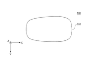
- FIG. 1A is a schematic front view of the flavor inhaler 100 according to this embodiment.
- FIG. 1B is a schematic top view of the flavor inhaler 100 according to this embodiment.
- FIG. 1C is a schematic bottom view of the flavor inhaler 100 according to this embodiment.
- an XYZ orthogonal coordinate system may be attached for convenience of explanation. In this coordinate system, the Z axis points vertically upward, the XY plane is arranged to cut the flavor inhaler 100 horizontally, and the Y axis extends from the front to the back of the flavor inhaler 100. arranged to come out.
- the Z-axis can also be said to be the direction of insertion of consumables contained in the chamber 50 of the atomizing section 30 described later or the axial direction of the chamber 50 .
- the X-axis direction can also be said to be the longitudinal direction of the device in a plane perpendicular to the direction in which the consumable is inserted, or the direction in which the heating section and the power supply section are aligned.
- the Y-axis direction can also be said to be the lateral direction of the device in a plane perpendicular to the direction of insertion of the consumable.
- the direction parallel to the XY plane is the direction orthogonal to the axial direction of the chamber 50, and can also be called the radial direction.
- the circumferential direction refers to the circumferential direction around the insertion direction of the consumable or the axial direction of the chamber 50 .
- the flavor inhaler 100 is configured, for example, to generate an aerosol containing flavor by heating a stick-shaped consumable material having a flavor source containing an aerosol source.
- the flavor inhaler 100 can be composed of a slide cover 90 and a main body 120.
- the main body 120 has an outer housing 101 and a switch section 103 .
- Outer housing 101 forms the outermost housing of flavor inhaler 100 and is sized to fit in the user's hand. When a user uses the flavor inhaler 100, the body 120 can be held by hand to inhale the aerosol.
- Outer housing 101 may be configured by assembling a plurality of members.
- the outer housing 101 has an opening 101a into which consumables are inserted.
- the slide cover 90 is slidably attached to the outer housing 101 so as to close the opening 101a. Specifically, the slide cover 90 moves between a closed position (position shown in FIG. 1A) that closes the opening 101a of the outer housing 101 and an open position (position shown in FIG. 1B) that opens the opening 101a. It is configured to be movable along the outer surface of the outer housing 101 . For example, the user can manually operate the slide cover 90 to move the slide cover 90 between the closed position and the open position. The sliding cover 90 thereby allows or restricts access of consumables to the interior of the flavor inhaler 100 .
- the switch section 103 is used to switch the operation of the flavor inhaler 100 between on and off. For example, by operating the switch unit 103 with the consumable material inserted into the flavor inhaler 100, the user can supply power from a power source (not shown) to a heating unit (not shown) to heat the consumable material without burning it. can be done.
- the switch section 103 may have a switch provided outside the outer housing 101 or may have a switch positioned inside the outer housing 101 . When the switch is located inside the outer housing 101 , the switch is indirectly pressed by pressing the switch portion 103 on the surface of the outer housing 101 . In this embodiment, an example in which the switches of the switch section 103 are located inside the outer housing 101 will be described.
- the flavor inhaler 100 may further have a terminal (not shown).
- a terminal may be an interface that connects the flavor inhaler 100 to, for example, an external power source.
- the power source of the flavor inhaler 100 is a rechargeable battery
- current can flow from the external power source to the power source to charge the power source.
- data transmission cable to the terminal, data related to the operation of the flavor inhaler 100 may be transmitted to an external device.
- FIG. 2 is a schematic side cross-sectional view of consumable 110 .
- the flavor inhaler 100 and the consumable 110 may constitute a smoking system.
- consumable article 110 includes smokable article 111 , tubular member 114 , hollow filter portion 116 and filter portion 115 .
- a smokable article 111 is wrapped by a first wrapping paper 112 .
- the tubular member 114 , the hollow filter portion 116 and the filter portion 115 are wrapped with a second wrapping paper 113 different from the first wrapping paper 112 .
- the second wrapping paper 113 also wraps a portion of the first wrapping paper 112 that wraps the smokable article 111 .
- the tubular member 114, the hollow filter portion 116, the filter portion 115 and the smokable article 111 are connected.
- second wrapping paper 113 may be omitted and first wrapping paper 112 may be used to connect tubular member 114, hollow filter portion 116, and filter portion 115 to smokable article 111.
- the tubular member 114 and the second wrapping paper 113 covering the tubular member 114 may be provided with an aperture V. As shown in FIG.
- the opening V is a hole for facilitating the inflow of air from the outside normally by the user's suction, and the inflow of air can lower the temperature of the components and the air flowing in from the smokable article 111 .
- a lip release agent 117 is applied to the outer surface of the second wrapping paper 113 in the vicinity of the filter portion 115 side end to prevent the user's lips from sticking to the second wrapping paper 113 .
- the portion of the consumable product 110 to which the lip release agent 117 is applied functions as a mouthpiece for the consumable product 110 .
- the smokable material 111 may include a flavor source, such as tobacco, and an aerosol source.
- the first wrapping paper 112 around which the smokable article 111 is wrapped may be a breathable sheet member.
- Tubular member 114 may be a paper tube or hollow filter.
- the consumable item 110 includes a smokable article 111, a tubular member 114, a hollow filter portion 116, and a filter portion 115, but the configuration of the consumable item 110 is not limited to this.
- hollow filter portion 116 may be omitted, and cylindrical member 114 and filter portion 115 may be arranged adjacent to each other.
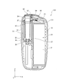
- FIG. 3 is a cross-sectional view of flavor inhaler 100 taken along line 3-3 shown in FIG. 1B.
- the slide cover 90 is positioned at the closed position.
- the inner housing 10 is accommodated inside the outer housing 101 of the flavor inhaler 100 .
- the inner housing 10 is made of, for example, a resin, particularly polycarbonate (PC), ABS (Acrylonitrile-Butadiene-Styrene) resin, PEEK (polyetheretherketone), or a polymer alloy containing a plurality of types of polymers, or It can be made of metal such as aluminum.
- the inner housing 10 is preferably made of PEEK.
- the material of the inner housing 10 is not particularly limited.
- a power supply section 20 and an atomization section 30 are provided in the inner space of the inner housing 10 .
- the outer housing 101 is made of, for example, a resin, particularly polycarbonate (PC), ABS (Acrylonitrile-Butadiene-Styrene) resin, PEEK (polyetheretherketone), or a polymer alloy containing a plurality of types of polymers. Alternatively, it may be made of metal such as aluminum.
- the power supply unit 20 has a power supply 21 .
- Power source 21 may be, for example, a rechargeable battery or a non-rechargeable battery.
- the power supply 21 is electrically connected to the atomizing section 30 via a PCB (Printed Circuit Board) (not shown) or the like. Thereby, the power source 21 can supply power to the atomization section 30 so as to appropriately heat the consumable material 110 .
- PCB Print Circuit Board
- the atomization section 30 includes a chamber 50 (corresponding to an example of a storage section) extending in the insertion direction (Z-axis direction) of the consumable material 110, a heating section 40 surrounding a part of the chamber 50, and a heat-insulating section. It has a portion 32 and a substantially cylindrical insertion guide member 34 .
- Chamber 50 is configured to contain consumables 110 .
- the chamber 50 is preferably made of a material having heat resistance and a small coefficient of thermal expansion.
- the chamber 50 can be made of metal such as stainless steel, resin such as PEEK, glass, or ceramic.
- a bottom member 36 may be provided at the bottom of the chamber 50 as shown. Bottom member 36 may act as a stop to position consumable 110 inserted into chamber 50 .
- the bottom member 36 has unevenness on the surface with which the consumable material 110 abuts, and can define a space capable of supplying air to the surface with which the consumable material 110 abuts.
- the bottom member 36 may be made of, for example, a resin material such as PEEK, metal, glass, ceramic, or the like, but is not particularly limited to this.
- the material forming the bottom member 36 may be a material having a lower thermal conductivity than the material forming the chamber 50 .
- an adhesive that can be composed of a resin material such as epoxy resin or an inorganic material can be used.
- the heating unit 40 is configured to contact the outer peripheral surface of the chamber 50 and heat the consumable material 110 housed in the chamber 50 .
- the heating section 40 may comprise a heating element, such as a heating track, and an electrically insulating sheet covering at least one side of the heating element. A detailed configuration of the heating unit 40 will be described later.
- the heat insulation part 32 is generally cylindrical as a whole, and is arranged so as to surround the chamber 50 and the heating part 40 .
- the heat insulating portion 32 may include, for example, an airgel sheet.
- the heat insulation part 32 is arranged so as to be separated from the chamber 50 and the heating part 40 , and an air layer is formed between the heat insulation part 32 and the chamber 50 and the heating part 40 .
- the insertion guide member 34 is made of a resin material such as PEEK, PC, or ABS, and is provided between the slide cover 90 in the closed position and the chamber 50 .
- the flavor inhaler 100 also has a first holding portion 37 and a second holding portion 38 for holding the heat insulating portion 32 .
- the first holding portion 37 and the second holding portion 38 can be made of elastomer such as silicone rubber, for example. As shown in FIG. 3, the first holding portion 37 holds the end portion of the heat insulating portion 32 on the Z-axis positive direction side. Also, the second holding portion 38 holds the end portion of the heat insulating portion 32 on the Z-axis negative direction side.
- the insertion guide member 34 has a function of guiding the insertion of the consumable item 110 . Specifically, when the slide cover 90 is in the open position, the insertion guide member 34 communicates with the opening 101a shown in FIG. , guides the consumables 110 into the chamber 50 . In this embodiment, since the insertion guide member 34 can come into contact with the chamber 50, the insertion guide member 34 is preferably made of PEEK from the viewpoint of heat resistance.
- the flavor inhaler 100 has a first chassis 22 extending in the Z-axis direction between the power source 21 and the atomizing section 30, and a second chassis 23 extending to cover the slide cover 90 side of the power source 21.
- the first chassis 22 and the second chassis 23 are configured to define a space within the inner housing 10 in which the power source 21 is housed.
- the flavor inhaler 100 further has a slider 94 that connects with the slide cover 90 .
- a slider 94 may be slidably attached to a portion of the inner housing 10 of the body 120 . This allows the slide cover 90 connected to the slider 94 to slide along the outer surface of the outer housing 101 of the main body 120 .
- the slide cover 90 can be fixed to the slider 94 with screws 92 .
- slider 94 may be fixed to a portion of inner housing 10 via spring 96 .
- a spring 96 is configured to bias the slider 94 to bias the slide cover 90 to the open or closed position.
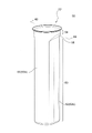
- FIG. 4A is a perspective view of chamber 50.
- FIG. 4B is a cross-sectional view of chamber 50 taken along line 4B-4B shown in FIG. 4A.
- 5A is a cross-sectional view of chamber 50 taken along line 5A-5A shown in FIG. 4B.
- 5B is a cross-sectional view of chamber 50 taken along line 5B-5B shown in FIG. 4B.
- the chamber 50 can be a tubular member that includes an opening 52 into which the consumable 110 is inserted and a tubular sidewall 60 that houses the consumable 110 .
- the chamber 50 is preferably made of a material having heat resistance and a small coefficient of thermal expansion.
- the chamber 50 can be made of metal such as stainless steel, resin such as PEEK, glass, or ceramic.
- the side wall portion 60 includes a flat portion 62 and a curved portion 66.
- Flat portion 62 contacts or presses against a portion of consumable 110 and curved portion 66 moves away from consumable 110 when consumable 110 is in the desired position within chamber 50 .
- the term "desired position within the chamber 50" refers to a position where the consumable 110 is properly heated or a position of the consumable 110 when smoked by the user.
- the flat portion 62 has a flat inner surface 62a and a flat outer surface 62b.
- the curved portion 66 has an inner surface 66a and an outer surface 66b.
- the chamber 50 has two flat portions 62 in the circumferential direction of the chamber 50, and the pair of flat portions 62 are parallel to each other. At least a portion of the distance between the inner surfaces 62a of the pair of flat portions 62 is preferably smaller than the width of the portion of the consumable 110 inserted into the chamber 50 that is positioned between the flat portions 62 .
- the inner surface 66a of the curved portion 66 can have a generally arcuate cross-section in a plane orthogonal to the longitudinal direction (Z-axis direction) of the chamber 50.
- the curved portion 66 is arranged so as to be adjacent to the flat portion 62 in the circumferential direction. In other words, the curved portion 66 is configured to connect respective ends of the pair of flat portions 62 .
- the chamber 50 may have a hole 56a in its bottom 56 through which the bottom member 36 shown in FIG. 3 is positioned inside the chamber 50 .
- the bottom member 36 may be secured within the bottom portion 56 of the chamber 50 by adhesive or the like.
- a bottom member 36 provided on the bottom portion 56 may support a portion of the consumable 110 inserted into the chamber 50 such that at least a portion of the end surface of the consumable 110 is exposed.
- the chamber 50 preferably has a tubular portion 54 between the opening 52 and the side wall portion 60. As shown in FIGS. A gap may be formed between the tubular portion 54 and the consumable 110 with the consumable 110 positioned at the desired location in the chamber 50 .
- the chamber 50 preferably has a first guide portion 58 having a tapered surface 58a connecting the inner surface of the cylindrical portion 54 and the inner surface 62a of the flat portion 62. As shown in FIGS.
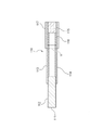
- FIG. 6 is a perspective view of the chamber 50 and the heating section 40.
- FIG. FIG. 7 is a schematic side cross-sectional view of the chamber 50 and the heating section 40 showing a state in which members forming the heating section 40 are overlapped.
- FIG. 8 is a schematic cross-sectional view of chamber 50 and heating section 40 taken along line 8-8 shown in FIG.
- the shrinkable tube 46 is omitted.
- FIG. 7 shows a state before each member is compressed by the shrinkable tube 46 so that the overlapping order of each member constituting the heating section 40 is clarified.
- 8 shows a cross section that does not include the thermistor 43 and the second tape member 45. As shown in FIG.
- side wall 60 of chamber 50 includes heating element 42, insulating member 70, first tape member 80, thermistor 43, second tape member 45, and shrink tube 46.
- heating element 42, the heat insulating member 70, the first tape member 80, the thermistor 43, the second tape member 45, and the shrinkable tube 46, which constitute the heating unit 40 are referred to as "outside and "inside” refer to the chamber 50;
- the heating element 42 is configured to heat the consumable material 110 contained in the chamber 50 from the outside.
- Heating element 42 may be, for example, a heating track.
- the heating element 42 may be provided on the outer surface of the side wall portion 60 of the chamber 50 or may be provided on the inner surface.
- the heating element 42 is affixed to the outer surface 62b of the flat portion 62 of the side wall portion 60.
- FIG. Heating element 42 is preferably positioned to heat flat portion 62 without contacting curved portion 66 of chamber 50 .
- the heating element 42 is preferably located only on the outer surface 62b or the inner surface 62a of the flat portion 62. As shown in FIG.
- the heating unit 40 may have an electrically insulating member (not shown) such as polyimide covering at least one surface of the heating element 42 , and the electrically insulating member is arranged to cover both surfaces of the heating element 42 . preferably.
- the heat insulating member 70 is provided on the outer circumference of the chamber 50 .
- the heating element 42 is attached to the outer surface of the flat portion 62 of the chamber 50 , so the heat insulating member 70 is provided so as to cover the outer surface of the heating element 42 .
- heating element 42 is sandwiched between flat portion 62 of chamber 50 and insulating member 70 .
- the heat insulating member 70 may be, for example, a fiber heat insulating material such as glass wool or rock wool, or a foam heat insulating material such as urethane foam or phenol foam.
- the first tape member 80 is attached to the heat insulating member 70 .
- the first tape member 80 is attached to the heat insulating member 70 so that the heat insulating member 70 is fixed with respect to the chamber 50 or is prevented from being displaced.
- a resin material such as polyimide (PI), polybenzimidazole (PBI), polyamideimide (PAI), liquid crystal polymer, glass cloth, or the like can be used. It is preferably a material having a property or an insulating property.
- the heat insulating member 70 is preferably wrapped around the outer circumference of the chamber 50 in one or more layers. Accordingly, since the chamber 50 is covered with the heat insulating member 70 over the entire circumferential length, it is possible to suppress the heat of the heated consumable material 110 from being transmitted to the outside of the apparatus. Moreover, as shown in FIG. 8, it is preferable that the heat insulating member 70 is wound around the outer circumference of the side wall portion 60 of the chamber 50 in two or more layers. In the example of FIG. 8, the heat insulating member 70 is wound around the outer periphery of the side wall portion 60 in approximately double. As a result, the heat insulating member 70 and the first tape member 80 have portions alternately arranged in layers on the side wall portion 60 of the chamber 50 . Thereby, it is possible to further suppress the heat of the heated consumable material 110 from being transferred to the outside of the apparatus.
- the heat insulating member 70 tends to have weak structural strength depending on the material.
- the heat insulating member 70 is a fiber-based heat insulating material such as glass wool
- the first tape member 80 is There is a risk that the member 80 will separate from the heat insulating member 70 . Therefore, in this embodiment, in order to properly arrange the heat insulating member 70 outside the chamber 50, the first tape members 80 are attached such that the first tape members 80 overlap each other.
- FIG. 9 is a developed plan view of the heat insulating member 70 and the first tape member 80 wound around the chamber 50.
- the heat insulating member 70 has a strip-like planar shape as a whole so as to be wrapped around the chamber 50 .
- the heat insulating member 70 has a first end 70 a and a second end 70 b that is the winding start end for the chamber 50 .
- the second end 70b is the end opposite the first end 70a.
- the first end portion 70 a forms an end portion of the heat insulating member 70 in the circumferential direction when the heat insulating member 70 is wound around the chamber 50 .
- the first tape member 80 has a first portion 80a extending from the first end 70a of the heat insulating member 70. As shown in FIG. This first portion 80 a is attached to the second portion 80 b of the first tape member 80 . As a result, the bonding strength of the first tape member 80 can be improved as compared with the case where the first portion 80a of the first tape member 80 is attached to the heat insulating member 70 . As a result, the heat insulating member 70 can be properly attached to the outside of the side wall portion 60 . In particular, when the heat insulating member 70 is a fiber heat insulating material, the bonding strength of the first tape member 80 can be improved compared to the case where the first portion 80a is attached to the fiber heat insulating material.
- the second portion 80b is attached onto the heat insulating member 70 .
- the heat insulating member 70 is wound approximately twice around the chamber 50 from the second end 70b at the winding start, so that the first portion 80a of the first tape member 80 is attached.
- the second portion 80 b may be located approximately in the central portion of the heat insulating member 70 .
- the first tape member 80 preferably has a fixed portion 80c that extends from the second end 70b of the heat insulating member 70 and is attached to the chamber 50 directly or indirectly.
- the fixed portion 80 c is attached to the outer surface of the heating element 42 so that the fixed portion 80 c is indirectly attached to the chamber 50 . can be attached. This allows the second end 70b of the first tape member 80 to be affixed and secured to the heating element 42 or the chamber 50 by the securing portion 80c.
- the fixing portion 80c can be attached directly to the chamber 50, such as when the heating element 42 is provided on the inner surface of the side wall portion 60 of the chamber 50.
- the fixed portion 80 c may be indirectly attached to the chamber 50 by being attached to another member fixed to the chamber 50 .
- the first tape member 80 is preferably attached to the heat insulating member 70 over the entire length of the heat insulating member 70 in the circumferential direction.
- the strength of the heat insulating member 70 can be improved by the first tape member 80 .
- the tensile strength of the heat insulating member 70 in the circumferential direction can be improved.
- the heat insulating member 70 can be attached to the chamber 50 by winding the first tape member 80, the heat insulating member 70 can be wound around the chamber 50 while being compressed. As a result, the thickness of the heat insulating member 70 can be easily adjusted.
- the first tape member 80 may be attached to the entire length of the heat insulating member 70 in the circumferential direction as a long piece of tape, or a plurality of tapes may be joined together to form the heat insulating member 70. It may be affixed over the entire length in the circumferential direction.
- FIG. 10 is a plan view of another example in which the heat insulating member 70 wound around the chamber 50 and the first tape member 80 are unfolded.
- the first tape member 80 may include a plurality of tape members 81,82.
- the tape member 81 is attached to the first end 70a of the insulating member 70 and includes a first portion 80a extending from the first end 70a.
- Tape member 82 may be affixed to second end 70b of insulating member 70 and have a securing portion 80c extending from second end 70b.
- the fixing portion 80c is attached directly or indirectly to the chamber 50, and the heat insulating member 70 starts winding around the chamber 50 from the second end 70b.
- the heat insulating member 70 is wrapped around the chamber 50 once and the first portion 80a is attached to the second portion 80b of the tape member 82 .
- the second portion 80b partially overlaps with the fixed portion 80c, but this is not a limitation, and the second portion 80b may completely match the fixed portion 80c, or may overlap with the fixed portion 80c. It may be a completely separate part. In other words, the second portion 80 b may be a portion extending from the heat insulating member 70 .
- the heat insulating member 70 is wound around the chamber 50 once, so that the heat insulating member 70 is formed shorter than the heat insulating member 70 shown in FIG.
- the length of the first tape member 80 in the axial direction is preferably 50% or more of the length of the heat insulating member 70 in the axial direction. This can prevent the heat insulating member 70 from being displaced with respect to the chamber 50 or the heating element 42 .
- the heat insulating member 70 has a higher coefficient of friction than the first tape member 80 which can generally be made of a resin material or the like.
- 50% or more of the insulation member 70 in the axial direction is covered by the first tape member 80, when the cylindrical shrink tube 46 is placed outside the insulation member 70 and the first tape member 80, the shrink tube Frictional force applied to 46 can be reduced. Therefore, a cylindrical member such as the shrinkable tube 46 can be easily arranged outside the heat insulating member 70 and the first tape member 80 .
- the heating element 42 is preferably positioned closer to the opening 52 than the bottom 56 of the chamber 50 .
- heating of the tip of the consumable item 110 by the heating element 42 is suppressed, so that the tip of the consumable item 110 is heated and shrinks, and the material of the consumable item (smokable material) is removed from the tip of the consumable item 110 . 111 etc.) can be suppressed from spilling.
- the tip side of the consumable material 110 can be cooled relatively more than the consumable material 110 on the side of the opening 52 into which the consumable material is inserted, sidestream smoke generated by heating the consumable material is cooled at the tip side.
- the heating element 42 near the opening 52 into which the consumable is inserted, the vapor generated due to the consumable 110 can be effectively sucked without condensing.
- the power density decreases and the heating rate decreases.
- a desired position in the chamber 50 can be heated by the heat transfer from the vapor, which effectively contributes to the efficient generation of the vapor.
- Thermistor 43 is configured to measure the temperature of consumable 110 , chamber 50 or heating element 42 .
- the thermistor 43 is electrically connected to a PCB (not shown) via wiring 43a, and can transmit temperature data to the PCB.
- the thermistor 43 is provided on the outer surface of the first tape member 80, as shown in FIGS.
- the thermistor 43 can be fixed more easily than when the thermistor 43 is provided on the outer surface of the heat insulating member 70 . Further, when the thermistor 43 is attached to the first tape member 80 by the second tape member 45, it can be attached again.
- the thermistor 43 is preferably located radially outside the heating element 42 . This allows the thermistor 43 to be placed near the heating element 42 so that the temperature of the heating element 42 or chamber 50 can be obtained accurately. Furthermore, as shown in FIGS. 6 and 7, the thermistor 43 is preferably positioned radially outward of the flat outer surface 62b of the flat portion 62. As shown in FIGS. This makes it easier to arrange the thermistor 43 on the outer surface of the first tape member 80 than when the thermistor 43 is arranged on the outer surface 66 b of the curved portion 66 .
- the thermistor 43 is positioned on the flat outer surface 62b, so that the distance between the heat insulating portion 32 and the thermistor 43 can be widened. , the physical contact between the heat insulating portion 32 and the thermistor 43 can be further suppressed.
- the second tape member 45 is configured to sandwich and fix the thermistor 43 together with the first tape member 80 .
- the second tape member 45 is adhered onto the thermistor 43 thereby securing the thermistor 43 to the outer surface of the first tape member 80 .
- the thermistor 43 is sandwiched between the first tape member 80 and the second tape member 45, so that the thermistor 43 can be attached to the first tape member 80 more firmly.
- the second tape member 45 may be omitted and the thermistor 43 may be fixed on the outer surface of the first tape member 80 with an adhesive or the like.
- the shrinkable tube 46 is tubular, arranged on the outermost side of the heating section 40 , and can be configured to fix each member constituting the heating section 40 to the chamber 50 .
- the shrink tube 46 may be positioned outside the second tape member 45 . This allows shrink tubing 46 to apply force to secure heating element 42 , insulation member 70 , first tape member 80 , thermistor 43 , and second tape member 45 against chamber 50 .
- the heating unit 40 does not have to include the thermistor 43 and the second tape member 45 .
- the shrink tube 46 may be positioned outside the first tape member 80 so as to contact the outer surface of the first tape member 80 .
- the shrinkable tube 46 may be, for example, a heat-shrinkable tube that shrinks when heat is applied while being arranged on the outer peripheral side of each member that constitutes the heating section 40 . By thermally shrinking the shrinkable tube 46 , each member constituting the heating section 40 can be pressed against the chamber 50 .
- the shrinkable tube 46 is a heat-shrinkable tube, it may be made of thermoplastic resin such as perfluoroalkoxy fluororesin (PFA).
- PFA perfluoroalkoxy fluororesin
- Thermal insulation part 40 Heating part 42: Heating element 43: Thermistor 45: Second tape member 46: Shrinkable tube 50: Chamber 52: Opening 56: Bottom part 60: Side wall part 62b: Outer surface 70: Thermal insulation member 70a: First end Part 70b: Second end 80: First tape member 80a: First part 80b: Second part 80c: Fixed part 81: Tape member 82: Tape member 100: Flavor sucker 110: Consumable material
Landscapes
- Packages (AREA)
- Thermotherapy And Cooling Therapy Devices (AREA)
- Disinfection, Sterilisation Or Deodorisation Of Air (AREA)
- Catching Or Destruction (AREA)
Abstract
Description
40 :加熱部
42 :加熱要素
43 :サーミスタ
45 :第2テープ部材
46 :収縮チューブ
50 :チャンバ
52 :開口
56 :底部
60 :側壁部
62b :外面
70 :断熱部材
70a :第1端部
70b :第2端部
80 :第1テープ部材
80a :第1部分
80b :第2部分
80c :固定部分
81 :テープ部材
82 :テープ部材
100 :香味吸引器
110 :消費材
Claims (14)
- 消費材を加熱可能な香味吸引器であって、
前記消費材が収容される収容部と、
前記消費材を加熱する加熱要素と、
前記収容部の外周に設けられる断熱部材と、
前記断熱部材に貼り付けられる第1テープ部材と、を有し、
前記第1テープ部材は、前記断熱部材の周方向における第1端部から延在する第1部分と、前記断熱部材上に位置するか又は前記断熱部材から延在する第2部分と、を有し、
前記第1部分が前記第2部分に貼り付けられる、香味吸引器。 - 請求項1に記載された香味吸引器において、
前記第1テープ部材は、前記断熱部材の前記第1端部とは反対側の第2端部から少なくとも一部が延在して前記加熱要素又は前記収容部に貼り付けられる固定部分を有する、香味吸引器。 - 請求項1又は2に記載された香味吸引器において、
前記第1テープ部材は、前記断熱部材の周方向の全長に亘って前記断熱部材に貼り付けられる、香味吸引器。 - 請求項1から3のいずれか一項に記載された香味吸引器において、
前記断熱部材は、前記収容部の外周に1重以上に巻き付けられる、香味吸引器。 - 請求項4に記載された香味吸引器において、
前記断熱部材は、前記収容部の外周に2重以上に巻き付けられる、香味吸引器。 - 請求項1から5のいずれか一項に記載された香味吸引器において、
前記第1テープ部材の外面上に設けられるサーミスタを有する、香味吸引器。 - 請求項6に記載された香味吸引器において、
前記サーミスタは、前記加熱要素の径方向外側に位置する、香味吸引器。 - 請求項6又は7に記載された香味吸引器において、
前記収容部は、筒状の側壁部を有し、
前記側壁部は、平坦な外面を有し、
前記サーミスタは、前記平坦な外面の径方向外側に位置する、香味吸引器。 - 請求項6から8のいずれか一項に記載された香味吸引器において、
前記サーミスタを前記第1テープ部材と共に挟み込んで固定する第2テープ部材を有する、香味吸引器。 - 請求項9に記載された香味吸引器において、
前記第2テープ部材の外側に位置する収縮チューブを有する、香味吸引器。 - 請求項1から10のいずれか一項に記載された香味吸引器において、
前記第1テープ部材の前記収容部の軸方向における長さは、前記断熱部材の前記軸方向における長さの50%以上である、香味吸引器。 - 請求項1から11のいずれか一項に記載された香味吸引器において、
前記断熱部材は、繊維系断熱材である、香味吸引器。 - 請求項1から12のいずれか一項に記載された香味吸引器において、
前記収容部は、前記消費材が挿入される開口と、前記消費材の端面と当接する底部と、を有し、
前記加熱要素は、前記底部よりも前記開口に近くなるように配置される、香味吸引器。 - 請求項1から13のいずれか一項に記載された香味吸引器において、
前記加熱要素は前記消費材を外側から加熱する、香味吸引器。
Priority Applications (7)
| Application Number | Priority Date | Filing Date | Title |
|---|---|---|---|
| KR1020237038482A KR20230169225A (ko) | 2021-04-26 | 2021-04-26 | 향미 흡인기 |
| PCT/JP2021/016605 WO2022230009A1 (ja) | 2021-04-26 | 2021-04-26 | 香味吸引器 |
| CN202180097464.7A CN117255629A (zh) | 2021-04-26 | 2021-04-26 | 香味吸取器 |
| JP2023516865A JPWO2022230009A1 (ja) | 2021-04-26 | 2021-04-26 | |
| EP21939173.7A EP4331397A1 (en) | 2021-04-26 | 2021-04-26 | Flavor inhaler |
| TW110137352A TW202241290A (zh) | 2021-04-26 | 2021-10-07 | 香味吸嚐器 |
| US18/466,684 US20230413909A1 (en) | 2021-04-26 | 2023-09-13 | Flavor inhaler |
Applications Claiming Priority (1)
| Application Number | Priority Date | Filing Date | Title |
|---|---|---|---|
| PCT/JP2021/016605 WO2022230009A1 (ja) | 2021-04-26 | 2021-04-26 | 香味吸引器 |
Related Child Applications (1)
| Application Number | Title | Priority Date | Filing Date |
|---|---|---|---|
| US18/466,684 Continuation US20230413909A1 (en) | 2021-04-26 | 2023-09-13 | Flavor inhaler |
Publications (1)
| Publication Number | Publication Date |
|---|---|
| WO2022230009A1 true WO2022230009A1 (ja) | 2022-11-03 |
Family
ID=83846775
Family Applications (1)
| Application Number | Title | Priority Date | Filing Date |
|---|---|---|---|
| PCT/JP2021/016605 WO2022230009A1 (ja) | 2021-04-26 | 2021-04-26 | 香味吸引器 |
Country Status (7)
| Country | Link |
|---|---|
| US (1) | US20230413909A1 (ja) |
| EP (1) | EP4331397A1 (ja) |
| JP (1) | JPWO2022230009A1 (ja) |
| KR (1) | KR20230169225A (ja) |
| CN (1) | CN117255629A (ja) |
| TW (1) | TW202241290A (ja) |
| WO (1) | WO2022230009A1 (ja) |
Citations (5)
| Publication number | Priority date | Publication date | Assignee | Title |
|---|---|---|---|---|
| JPH08135888A (ja) * | 1994-11-07 | 1996-05-31 | Sekisui Chem Co Ltd | 断熱保温テープ |
| JP2009299760A (ja) * | 2008-06-12 | 2009-12-24 | Imae Kogyo Kk | 熱機器の断熱装置 |
| JP2019525737A (ja) * | 2016-06-29 | 2019-09-12 | フィリップ・モーリス・プロダクツ・ソシエテ・アノニム | 温度依存電池予備加熱を備える電池式エアロゾル発生装置 |
| WO2019208536A1 (ja) * | 2018-04-26 | 2019-10-31 | 日本たばこ産業株式会社 | ヒータアッセンブリ及び容器 |
| WO2020084775A1 (ja) | 2018-10-26 | 2020-04-30 | 日本たばこ産業株式会社 | 制御ユニット、エアロゾル生成装置、ヒータを制御する方法及びプログラム、並びに喫煙物品 |
Family Cites Families (1)
| Publication number | Priority date | Publication date | Assignee | Title |
|---|---|---|---|---|
| JP7228994B2 (ja) | 2018-11-15 | 2023-02-27 | 株式会社小松製作所 | ピストン及び油圧ポンプ・モータ |
-
2021
- 2021-04-26 JP JP2023516865A patent/JPWO2022230009A1/ja active Pending
- 2021-04-26 EP EP21939173.7A patent/EP4331397A1/en active Pending
- 2021-04-26 WO PCT/JP2021/016605 patent/WO2022230009A1/ja active Application Filing
- 2021-04-26 KR KR1020237038482A patent/KR20230169225A/ko unknown
- 2021-04-26 CN CN202180097464.7A patent/CN117255629A/zh active Pending
- 2021-10-07 TW TW110137352A patent/TW202241290A/zh unknown
-
2023
- 2023-09-13 US US18/466,684 patent/US20230413909A1/en active Pending
Patent Citations (5)
| Publication number | Priority date | Publication date | Assignee | Title |
|---|---|---|---|---|
| JPH08135888A (ja) * | 1994-11-07 | 1996-05-31 | Sekisui Chem Co Ltd | 断熱保温テープ |
| JP2009299760A (ja) * | 2008-06-12 | 2009-12-24 | Imae Kogyo Kk | 熱機器の断熱装置 |
| JP2019525737A (ja) * | 2016-06-29 | 2019-09-12 | フィリップ・モーリス・プロダクツ・ソシエテ・アノニム | 温度依存電池予備加熱を備える電池式エアロゾル発生装置 |
| WO2019208536A1 (ja) * | 2018-04-26 | 2019-10-31 | 日本たばこ産業株式会社 | ヒータアッセンブリ及び容器 |
| WO2020084775A1 (ja) | 2018-10-26 | 2020-04-30 | 日本たばこ産業株式会社 | 制御ユニット、エアロゾル生成装置、ヒータを制御する方法及びプログラム、並びに喫煙物品 |
Also Published As
| Publication number | Publication date |
|---|---|
| TW202241290A (zh) | 2022-11-01 |
| KR20230169225A (ko) | 2023-12-15 |
| EP4331397A1 (en) | 2024-03-06 |
| US20230413909A1 (en) | 2023-12-28 |
| JPWO2022230009A1 (ja) | 2022-11-03 |
| CN117255629A (zh) | 2023-12-19 |
Similar Documents
| Publication | Publication Date | Title |
|---|---|---|
| CA3095711C (en) | Vapour provision systems, liquid transport elements and vaporisers for vapour provision systems, and methods of assembly | |
| JP7463556B2 (ja) | 香味吸引器 | |
| WO2019193311A1 (en) | Vapour provision systems | |
| JP2024057043A (ja) | 香味吸引器 | |
| WO2022230009A1 (ja) | 香味吸引器 | |
| WO2022123766A1 (ja) | 香味吸引器及び香味吸引器の製造方法 | |
| JP7204918B2 (ja) | 加熱アセンブリおよび香味吸引器 | |
| WO2022123761A1 (ja) | 香味吸引器および圧力緩和方法 | |
| WO2022123760A1 (ja) | 香味吸引器 | |
| WO2023286194A1 (ja) | 香味吸引器及びヒータの製造方法 | |
| WO2023286193A1 (ja) | 香味吸引器及びヒータの製造方法 | |
| WO2022230127A1 (ja) | 香味吸引器及び香味吸引器の製造方法 | |
| EP3871533A1 (en) | Heating assembly and flavor inhaler provided with same | |
| WO2023218586A1 (ja) | エアロゾル生成システム、及びエアロゾル生成システムの製造方法 | |
| WO2022230086A1 (ja) | 香味吸引器および香味吸引器の製造方法 | |
| WO2023058220A1 (ja) | 香味吸引器 | |
| WO2022123759A1 (ja) | 香味吸引器および香味吸引器の製造方法 | |
| JP2023113847A (ja) | 香味吸引器 | |
| WO2023127048A1 (ja) | 非燃焼型香味吸引器の本体ユニット及び非燃焼型香味吸引器 | |
| WO2023112145A1 (ja) | 霧化ユニット及び香味吸引器 | |
| WO2022123770A1 (ja) | 香味吸引器及び香味吸引器の製造方法 | |
| WO2023112143A1 (ja) | 霧化ユニット及び香味吸引器 | |
| WO2023112182A1 (ja) | 香味吸引器 | |
| KR20230173693A (ko) | 향미 흡인기 |
Legal Events
| Date | Code | Title | Description |
|---|---|---|---|
| 121 | Ep: the epo has been informed by wipo that ep was designated in this application |
Ref document number: 21939173 Country of ref document: EP Kind code of ref document: A1 |
|
| ENP | Entry into the national phase |
Ref document number: 2023516865 Country of ref document: JP Kind code of ref document: A |
|
| WWE | Wipo information: entry into national phase |
Ref document number: 202180097464.7 Country of ref document: CN |
|
| ENP | Entry into the national phase |
Ref document number: 20237038482 Country of ref document: KR Kind code of ref document: A |
|
| WWE | Wipo information: entry into national phase |
Ref document number: 1020237038482 Country of ref document: KR |
|
| WWE | Wipo information: entry into national phase |
Ref document number: 2021939173 Country of ref document: EP |
|
| NENP | Non-entry into the national phase |
Ref country code: DE |
|
| ENP | Entry into the national phase |
Ref document number: 2021939173 Country of ref document: EP Effective date: 20231127 |