WO2023218565A1 - 除湿機 - Google Patents
除湿機 Download PDFInfo
- Publication number
- WO2023218565A1 WO2023218565A1 PCT/JP2022/019969 JP2022019969W WO2023218565A1 WO 2023218565 A1 WO2023218565 A1 WO 2023218565A1 JP 2022019969 W JP2022019969 W JP 2022019969W WO 2023218565 A1 WO2023218565 A1 WO 2023218565A1
- Authority
- WO
- WIPO (PCT)
- Prior art keywords
- airflow
- air
- opening
- dehumidifier
- closing
- Prior art date
- Legal status (The legal status is an assumption and is not a legal conclusion. Google has not performed a legal analysis and makes no representation as to the accuracy of the status listed.)
- Ceased
Links
Images


Classifications
-
- F—MECHANICAL ENGINEERING; LIGHTING; HEATING; WEAPONS; BLASTING
- F24—HEATING; RANGES; VENTILATING
- F24F—AIR-CONDITIONING; AIR-HUMIDIFICATION; VENTILATION; USE OF AIR CURRENTS FOR SCREENING
- F24F1/00—Room units for air-conditioning, e.g. separate or self-contained units or units receiving primary air from a central station
- F24F1/02—Self-contained room units for air-conditioning, i.e. with all apparatus for treatment installed in a common casing
- F24F1/0328—Self-contained room units for air-conditioning, i.e. with all apparatus for treatment installed in a common casing with means for purifying supplied air
- F24F1/035—Self-contained room units for air-conditioning, i.e. with all apparatus for treatment installed in a common casing with means for purifying supplied air characterised by the mounting or arrangement of filters
-
- F—MECHANICAL ENGINEERING; LIGHTING; HEATING; WEAPONS; BLASTING
- F24—HEATING; RANGES; VENTILATING
- F24F—AIR-CONDITIONING; AIR-HUMIDIFICATION; VENTILATION; USE OF AIR CURRENTS FOR SCREENING
- F24F1/00—Room units for air-conditioning, e.g. separate or self-contained units or units receiving primary air from a central station
- F24F1/02—Self-contained room units for air-conditioning, i.e. with all apparatus for treatment installed in a common casing
- F24F1/0358—Self-contained room units for air-conditioning, i.e. with all apparatus for treatment installed in a common casing with dehumidification means
-
- F—MECHANICAL ENGINEERING; LIGHTING; HEATING; WEAPONS; BLASTING
- F24—HEATING; RANGES; VENTILATING
- F24F—AIR-CONDITIONING; AIR-HUMIDIFICATION; VENTILATION; USE OF AIR CURRENTS FOR SCREENING
- F24F2130/00—Control inputs relating to environmental factors not covered by group F24F2110/00
- F24F2130/20—Sunlight
Definitions
- the present disclosure relates to a dehumidifier.
- a dehumidifier is described in Patent Document 1.
- the dehumidifier shown in Patent Document 1 dehumidifies air taken in from an intake port by passing it through a heat exchanger.
- the filter is arranged between the air intake port and the heat exchanger so as not to cover the front side of the heat exchanger, that is, a portion of the upstream side of the airflow when viewed from the heat exchanger.
- a shutter is provided to block air flow. The shutter is selectively provided in a position where it covers a portion of the passage to the heat exchanger and a position where it does not cover the passage.
- An object of the present disclosure is to provide a dehumidifier that can be operated efficiently.
- the dehumidifier according to the present disclosure includes a casing in which an inlet and an outlet are formed, a blowing means for generating an airflow from the inlet to the outlet, and a dehumidifier that is disposed inside the casing and is detachable.
- the dehumidifier includes an air purifying means provided in the casing, and a dehumidifying means disposed inside the casing to remove moisture from the airflow.
- This dehumidifier includes a first air path formed inside the housing, through which the airflow passes through the air purifying means, and reaches the dehumidification means; a second air path leading to the dehumidifying means without passing through the air purifying means; an air flow restricting means for restricting airflow flowing through the second air path; and a compressor for supplying refrigerant to the dehumidifying means.
- a control device for controlling the air blowing means, the air flow restricting means, and the compressor, and an attachment/detachment detection means for detecting the attachment/detachment state of the air purifying means. The control device controls the air blower according to the detection result of the attachment/detachment detection means.
- the dehumidifier includes a casing in which an inlet and an outlet are formed, a blower for generating an airflow from the inlet to the outlet, and disposed inside the casing,
- the dehumidifier includes an air purifying means that is detachably provided, and a dehumidifying means that is disposed inside the housing and removes moisture from the airflow.
- This dehumidifier includes a first air path formed inside the housing, through which the airflow passes through the air purifying means, and reaches the dehumidification means; Selecting a second air path that reaches the dehumidifying means without passing through the air purifying means, a state in which the air flow in the second air path is allowed to pass, and a state in which the air flow in the second air path is blocked.
- a compressor that supplies refrigerant to the dehumidifying means; and a control device that controls the blowing means, the opening and closing means, and the compressor.
- the opening/closing means is disposed within the second air path and is supported by two shafts in the vertical direction of the housing.
- a motor with a position control function is connected to one side of the two shafts, and an opening/closing detection means for detecting whether the opening/closing means is open or closed is provided on the other side.
- FIG. 2 is a perspective view of the dehumidifier of Embodiment 1 seen from the front side.
- FIG. 2 is a perspective view of the dehumidifier of Embodiment 1 seen from the back side.
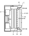
- 2 is a vertical cross-sectional view taken along line AA shown in FIG. 1.
- FIG. 2 is a horizontal cross-sectional view taken along line BB shown in FIG. 1.
- FIG. FIG. 2 is a block diagram showing the main control configuration of the dehumidifier according to the first embodiment.
- FIG. 2 is a perspective view of the dehumidifier of Embodiment 1 with the suction port cover, HEPA filter, and activated carbon filter removed, as seen from the back side.
- FIG. 3 is a schematic diagram for easily explaining the flow of air in the first embodiment.
- FIG. 1 is a simplified diagram showing the configuration of a shutter in Embodiment 1.
- FIG. FIG. 2 is a cross-sectional view of a main part when a shutter is shielding a bypass air path in Embodiment 1;
- FIG. 2 is a sectional view of a main part when the shutter opens a bypass air path in the first embodiment.
- 5 is a flowchart showing operational steps during dehumidifying operation of the dehumidifier of Embodiment 1.
- FIG. 3 is a flowchart showing operational steps during air purifying operation of the dehumidifier of Embodiment 1.
- FIG. 2 is a flowchart showing operational steps during dehumidifying air cleaning operation of the dehumidifier of the first embodiment.
- 3 is a flowchart showing the basic operation steps of the control device when starting the operation of the dehumidifier according to the first embodiment.
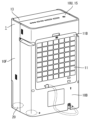
- FIG. 1 is a perspective view of a dehumidifier 1 according to the first embodiment seen from the front side.
- FIG. 2 is a perspective view of the dehumidifier 1 according to the first embodiment, viewed from the back side.
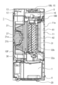
- FIG. 3 is a vertical cross-sectional view taken along line AA shown in FIG.
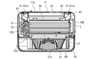
- FIG. 4 is a horizontal cross-sectional view taken along line BB shown in FIG.
- FIG. 5 is a block diagram showing the main control configuration of the dehumidifier according to the first embodiment.
- the dehumidifier 1 will be described based on the state in which the dehumidifier 1 is placed on a horizontal surface such as a floor surface.
- the dehumidifier 1 includes a front case 10F and a rear case 10B.
- the front case 10F and the rear case 10B are members that constitute a casing that forms the outer shell of the dehumidifier 1.
- the housing of the dehumidifier 1 has a bottom plate 4 to which a plurality of wheels 20 are attached.
- the front case 10F, the rear case 10B, and the bottom plate 4 constitute a hollow box-shaped casing.
- a plurality of wheels 20 for moving the dehumidifier 1 are attached to the bottom plate 4.
- the plurality of wheels 20 are arranged one each at positions apart from each other in the front, back, left and right, that is, a total of four wheels 20 are arranged.
- a heavy object such as a compressor is placed on the bottom plate 4. Note that in the present disclosure, illustration of the compressor is omitted for clarity and simplification of the description of the drawings.
- the front case 10F and the rear case 10B are assembled into one box shape by being connected with a coupling device such as a screw, for example.
- the front case 10F is a member that forms the front part of the dehumidifier 1.
- the rear case 10B is a member that forms the back part of the dehumidifier 1.
- a flat upper case 10U is connected to the upper ends of the front case 10F and the rear case 10B.
- a louver 13 is provided at the front of the upper case 10U.
- the upper case 10U and the louver 13 are arranged so as to face each other and come into contact with each other from the front and rear.
- the louver 13 in the closed state forms one flat surface together with the upper case 10U. This surface is the top surface of the casing of the dehumidifier 1.
- a suction port 11 and an air outlet 12 are formed in the casing of the dehumidifier 1.
- the suction port 11 is an opening for taking air into the dehumidifier 1 from the outside.
- the air outlet 12 is an opening for sending air from the inside of the dehumidifier 1 to the outside.
- the suction port 11 is formed as a square window-shaped opening in the center of the rear case 10B.
- the air outlet 12 is formed on the top surface of the dehumidifier 1.
- a louver 13 is arranged at a location where the air outlet 12 is formed. The air outlet 12 is opened by opening the louver 13 upward to a certain angle.
- the suction port 11 has a square shape when the dehumidifier 1 is viewed from the back side.
- the shape of this suction port 11 is not limited to this example, and may be rectangular or circular, for example.
- the dehumidifier 1 includes a suction port cover 11a that covers the suction port 11.
- the suction port cover 11a is a member that prevents foreign matter from entering the inside of the dehumidifier 1 through the suction port 11.
- the suction port cover 11a prevents foreign matter, such as paper scraps and fiber scraps, which are thrown into the air, from entering the inside of the dehumidifier 1, for example.
- the suction port cover 11a is detachably fixed to the rear case 10B.
- the suction port cover 11a is formed, for example, in a grid shape.
- the suction port cover 11a may be formed into a shutter shape, for example.
- a net may be attached to the entire surface of the suction port cover 11a to prevent foreign matter from entering.
- the suction port cover 11a may be formed as a net-shaped member by integral molding of a plastic material.
- the dehumidifier 1 includes a compressor (not shown).
- the compressor may be of any type, such as a reciprocating type or a rotary type.
- the compressor has a motor and circulates refrigerant through the refrigerant pipe 22 connected to the evaporator 31, the first condenser 32a, and the second condenser 32b.
- the compressor is connected to an evaporator 31, a first condenser 32a, a second condenser 32b, and a pressure reducing device (not shown) through a refrigerant pipe 22 to form a refrigerant circuit using a refrigeration cycle.
- the compressor compresses and supplies refrigerant to the refrigerant circuit.
- the evaporator 31, the first condenser 32a, and the second condenser 32b are heat exchangers for exchanging heat between the refrigerant and air.
- a pressure reducing device is a device that reduces the pressure of a refrigerant.
- the pressure reducing device is, for example, an expansion valve or a capillary tube.
- the dehumidifier 1 includes a water storage tank 7. Drain water generated on the external surface of the evaporator 31 during the dehumidifying operation is dripped and guided to the water storage tank 7 .
- the water storage tank 7 can be taken out from an outlet formed in the front case 10F.
- the louver 13 is composed of a single plate-shaped member or a plurality of plate-shaped members.
- the louver 13 is for adjusting the direction in which air is sent out from the air outlet 12, and is installed so as to be openable and closable.
- louver driving motor 13M shown in FIG. 5 is connected to the louver 13.
- the posture of the louver 13 is changed by this louver drive motor 13M.
- the louver drive motor 13M allows the louver 13 to change its inclination angle with respect to the air outlet 12 in several stages. Thereby, the direction of air blown out from the air outlet 12 can be adjusted.
- louver drive motor 13M The operation of the louver drive motor 13M is controlled by a drive signal from a drive circuit 13A mounted on a control board (not shown).
- the control board is housed in a board box 16 formed as a case made of metal or nonflammable heat-resistant plastic.
- control board includes an inverter circuit 27 for driving the compressor, and a drive circuit 28 for driving the fan 21, which will be described later.
- the dehumidifier 1 includes an operation notification section 15.
- the operation notification section 15 includes an input operation section 17 for the user to operate the dehumidifier 1, and a notification section 23 for making various notifications.
- the notification unit 23 displays, for example, the status of the dehumidifier 1 and the like using visible information such as characters. Further, the notification unit 23 may also be capable of providing audio notification.
- the operation notification section 15 is arranged on the top of the dehumidifier 1.
- An operation display board 8 for controlling the operation notification section 15 is arranged inside the upper case 10U so as to face the operation notification section 15.
- An operation switch for starting and stopping the operation of the dehumidifier 1 is arranged in the input operation section 17.
- the input operation unit 17 is an operation mode for switching the operation mode of the dehumidifier 1 to any one of three types: "dehumidification operation mode”, “air purification operation mode”, and “dehumidification air purification operation mode”. It has a changeover switch 17S.
- a fan 21 is housed inside the dehumidifier 1.
- the fan 21 is a device that takes air into the dehumidifier 1 and sends the taken air to the outside of the dehumidifier 1.
- the fan 21 generates an airflow from the suction port 11 to the blowout port 12 in an air path from the suction port 11 to the blowout port 12 by rotating.
- a motor 21a is housed inside the dehumidifier 1.
- the motor 21a is a device that rotates the fan 21.
- fan 21 and motor 21a are arranged on the front side of dehumidifier 1.
- the motor 21a is connected to the rotation center of the fan 21 via a rotation shaft 21b extending in the horizontal direction.
- the fan 21 and the motor 21a constitute an example of a blowing means that generates an airflow from the suction port 11 to the blowout port 12.
- the start of rotation, the stop of rotation, and the rotation speed of the motor 21a are controlled by a drive circuit 28.
- the fan 21 is, for example, a sirocco fan.
- the center of rotation of the fan 21 is fixed by a rotating shaft 21b.
- the fan 21 sucks air into the fan case 36 from the front and blows the air out from the air outlet 12.
- the fan case 36 surrounds the fan 21 and the motor 21a.
- a bell mouth portion 37 is formed on the front wall surface of the fan case 36 at a position corresponding to the fan 21.
- This bell mouth portion 37 is a large circular opening, and its mouth edge is largely curved toward the leeward side.
- the bell mouth portion 37 is configured to smoothly suck in the airflow that has passed through the first condenser 32a.
- the dehumidifier 1 of the present embodiment includes an evaporator 31, a first condenser 32a, and a second condenser 32b as an example of a dehumidifying means for removing moisture in the airflow from the suction port 11 to the blowout port 12. .
- the evaporator 31, the first condenser 32a, and the second condenser 32b are housed inside the casing of the dehumidifier 1. As shown in FIG. 4, the evaporator 31, the first condenser 32a, and the second condenser 32b are each installed vertically so as to close the front side of the bell mouth portion 37.
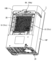
- FIG. 6 is a perspective view of the dehumidifier 1 according to the first embodiment, with the suction port cover 11a, HEPA filter 41, and activated carbon filter 42 removed, as seen from the back side.
- the dehumidifier 1 includes a flow regulating member 38.
- the flow regulating member 38 is formed from a frame-shaped member that intersects in the vertical direction and the horizontal direction, and a large number of ventilation windows are formed between each frame. In other words, this rectifying member 38 forms a grid-like member.
- the rectifying member 38 faces the rear surface of the evaporator 31 with a first space in between. That is, the rectifying member 38 faces the evaporator 31 at a predetermined distance.
- this rectifying member 38 faces the front surface of the activated carbon filter 42 with a second space in between. That is, the rectifying member 38 faces the front surface of the activated carbon filter 42 with a predetermined distance therebetween.
- the dehumidifier 1 of this embodiment includes a HEPA filter 41 and an activated carbon filter 42, which are air purifying filters for purifying the air, as an example of air purifying means for removing dust, odor, etc. from the air.
- HEPA filter 41 and activated carbon filter 42 are housed inside rear case 10B.
- the HEPA filter 41 is a filter that collects fine dust in the air.
- HEPA filter 41 is an example of a first filter that collects dust from airflow.
- the activated carbon filter 42 is a filter that deodorizes the air.
- Activated carbon filter 42 is an example of a second filter that removes odors from the airflow. As described above, the activated carbon filter 42 is placed a predetermined distance apart from the rear surface of the flow regulating member 38.
- the HEPA filter 41 and activated carbon filter 42 can be inserted up to the rear position of the flow regulating member 38 with the suction port cover 11a removed from the rear case 10B.
- the HEPA filter 41 and the activated carbon filter 42 can be detachably installed inside the rear case 10B.
- a filter detection section 64 is provided in the rear case 10B as an example of an attachment/detachment means for detecting the attachment/detachment state of a filter, which is an air purifying means.
- the filter detection unit 64 includes a detection lever 64a that is pressed down by the edge of the HEPA filter 41 and a detection switch. The detection lever 64a is pressed down when the HEPA filter 41 is installed, and when the detection lever 64a is pressed down, the detection switch is pressed and turned on. The ON state and OFF state of the detection switch can be determined by the presence or absence of an electric signal.
- the rectifying member 38 also serves as a protective member to prevent the user from touching the evaporator 31 when the HEPA filter 41 and activated carbon filter 42 are removed from the rear case 10B. For example, even if a user pushes the rectifying member 38 from the front with a finger or the like, the finger or the like will not touch the evaporator 31.
- an air path leading from the suction port 11 to the outlet 12 is formed inside the dehumidifier 1.
- the airflow flowing inside the air passage passes through the suction port 11, the suction port cover 11a, the HEPA filter 41, the activated carbon filter 42, the evaporator 31, the second condenser 32b, the first condenser 32a, and the fan 21 in this order.
- a series of air passages are formed through which air entering from the suction port 11 passes through a filter, which is an air purifying means, and flows from each heat exchanger toward the fan 21.
- the upstream side and the downstream side are defined using the airflow flowing through the air path leading from the inlet 11 to the outlet 12.
- the side where the suction port 11 is located with respect to the heat exchanger such as the evaporator 31 is defined as the upstream side.
- the side where the air outlet 12 is located with respect to the heat exchanger such as the evaporator 31 is defined as the downstream side.
- the dehumidifier 1 includes a dust sensor 62.
- This dust sensor 62 is arranged inside the dehumidifier 1.
- a small opening is provided near the dust sensor 62 so that the dust sensor 62 communicates with the outside of the dehumidifier 1.
- Dust sensor 62 and control device 18 can acquire dust detection information.
- the dust sensor 62 and the control device 18 can measure the amount and concentration of dust in the indoor space where the dehumidifier 1 is installed.
- the dust sensor 62 has the ability to detect particles of 0.1 ⁇ m, for example.
- the detection result of the dust sensor 62 is acquired by the control device 18, and the acquired dust detection information can be displayed on the operation notification section 15.
- the dehumidifier 1 includes a gas sensor 63.
- This gas sensor 63 is arranged inside the dehumidifier 1, and a small opening is provided near the gas sensor 63 so that the gas sensor 63 communicates with the outside of the dehumidifier 1.
- Gas detection information is acquired by the gas sensor 63 and the control device 18, and the odor of indoor air can be measured.
- the detection result of the gas sensor 63 is acquired by the control device 18, and the acquired gas detection information can be displayed on the operation notification section 15.
- the dehumidifier 1 includes a wireless communication section 26.
- the wireless communication unit 26 is housed near the ceiling inside the upper case 10U.
- the wireless communication unit 26 is capable of wireless communication with local network equipment such as a wireless router installed in the home or office where the dehumidifier 1 is located.
- the wireless communication unit 26 may be connected to the Internet line via local network equipment.
- the wireless communication unit 26 can exchange information with an information processing terminal such as a smartphone and other communication devices located at a remote location via an Internet line.
- the local network equipment may be a command device that controls the total amount of electricity used in a home or office, or an integrated management device that collects and coordinates information on multiple electrical devices. Also called "point".
- bypass air passages 43 adjacent to the left and right sides of the HEPA filter 41 and the activated carbon filter 42.
- the bypass air passage 43 is a space provided throughout the height direction of the suction port 11 inside the rear case 10B.
- the bypass air path 43 is an air path that extends forward from the suction port 11.
- the bypass air passage 43 is a narrow space extending from the rear to the front.
- the bypass air passage 43 is an air passage sandwiched between a bypass air passage outer wall 43a and a filter case outer wall 43b.
- the gap between the rear end of the bypass air passage outer wall 43a and the rear end of the filter case outer wall 43b serves as an entrance to the bypass air passage 43.
- the front end of the bypass air passage outer wall 43a is in contact with the outer peripheral end of the flow regulating member 38, so that airflow does not leak outside in the middle of the bypass air passage 43.
- a gap between the front end of the bypass air passage outer wall 43a and the front end of the filter case outer wall 43b serves as an outlet of the bypass air passage 43.
- the air passage leading from the inlet 11 to the outlet 12 includes two air passages: a main air passage 44 that is a first air passage and a bypass air passage 43 that is a second air passage. It is configured.
- the main air passage 44 is an air passage that extends from the suction port 11 through the HEPA filter 41 and the activated carbon filter 42 and reaches the flow regulating member 38.
- the bypass air passage 43 is an air passage from the suction port 11 to the rectifying member 38 without passing through the HEPA filter 41 and the activated carbon filter 42 .
- the main air passage 44 and the bypass air passage 43 join immediately before the flow straightening member 38.
- the dehumidifier 1 includes an airflow restriction means 51 for substantially opening and closing the inlet of the bypass airway 43 to restrict the airflow flowing through the bypass airway 43.
- the airflow restricting means 51 are arranged on the left and right sides of the suction port 11, respectively. Note that as the configuration of the airflow restricting means 51, any configuration can be adopted as long as it is capable of restricting the airflow flowing through the bypass air path 43.
- a configuration will be described in which a shutter 51s, which is an opening/closing means, is adopted.
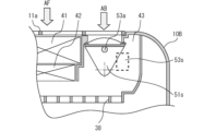
- FIG. 7 is a schematic diagram for easily explaining the flow of air in the first embodiment.
- the bypass air passage 43 is an air passage through which the air flow AB flows downstream without passing through the HEPA filter 41 and the activated carbon filter 42.
- a main air path 44 is an air path through which the airflow AF passes through the HEPA filter 41 and the activated carbon filter 42.
- bypass air passages 43 are formed on the right and left sides of the HEPA filter 41 and activated carbon filter 42, respectively.
- the bypass air passage 43 and the main air passage 44 are arranged adjacent to each other on the left and right in parallel.
- the airflow AB passing through the bypass air passage 43 and the airflow AF passing through the main air passage 44 do not merge inside the HEPA filter 41 and the activated carbon filter 42.
- the air path inside the dehumidifier 1 is improved.
- the air path inside the dehumidifier 1 is improved.
- the vertical height of the bypass air passage 43 is set to be approximately the same as the length of the HEPA filter 41 in the vertical direction.
- the bypass airflow AB flowing in the bypass airflow path 43 and the main airflow AF flowing in the main airflow path 44 are connected to a space downstream of the activated carbon filter 42, that is, a first space a certain distance apart from the rectification member 38 as a starting point, and a rectification. Starting from the member 38, it merges with a second space spaced a certain distance apart.
- the bypass airflow AB and the main airflow AF merge before the evaporator 31 located downstream of the activated carbon filter 42, and thereafter flow in one air path.
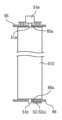
- FIG. 8 is a simplified diagram showing the configuration of the shutter 51s of the first embodiment.
- FIG. 9 is a sectional view of a main part when the shutter 51s is shielding the bypass air passage 43 in the first embodiment.
- FIG. 10 is a sectional view of a main part when the shutter 51s opens the bypass air passage 43 in the first embodiment.
- the shutter 51s is provided in the bypass air passage 43.
- the shutter 51s is supported by two shafts in the vertical direction of the casing of the dehumidifier 1.
- the shutter 51s has an upper rotation shaft 51a and a lower rotation shaft 51b.
- the upper bypass wall 65 and lower bypass wall 66 of the bypass air passage 43 are provided with an upper bearing 65a and a lower bearing 66a, respectively.
- the upper rotation shaft 51a and the lower rotation shaft 51b of the shutter 51s are inserted into the upper bearing 65a and the lower bearing 66a, respectively, so that the shutter 51s is rotatable.
- a shutter motor 51m is arranged inside the bypass upper wall 65 of the bypass air passage 43.
- the upper rotating shaft 51a of the shutter 51s is connected to the rotating shaft of the shutter motor 51m.
- the shutter motor 51m is a motor with a position control function. By controlling the rotational position of the shutter motor 51m, the shutter 51s can be moved to a position where the airflow in the bypass air path 43 is blocked, as shown in FIG. 9, and a position where the airflow is allowed to pass through the bypass air path 43, as shown in FIG. It rotates between .
- the shutter 51s can select between a state in which the airflow in the bypass air path 43, which is the second air path, is allowed to pass through and a state in which the airflow in the bypass air path 43 is blocked.
- the shutter 51s is provided with an opening/closing detection section 53 as an opening/closing detection means for detecting whether the shutter 51s is in an open state or a closed state.
- an opening/closing detection section 53 can be configured arbitrarily, the opening/closing detection sensor 53s will be described here as an example.
- An opening/closing detection sensor 53s is arranged inside the bypass lower wall 66 of the bypass air passage 43. The opening/closing detection sensor 53s detects magnetism to turn ON/OFF a signal, and can use, for example, a Hall IC or a reed switch.
- a magnet 53a is installed on the wall surface of the lower end of the shutter 51s.
- a magnet 53a is installed at a position facing the opening/closing detection sensor 53s when the shutter 51s is in a position to open the bypass air passage 43.
- the opening/closing detection sensor 53s detects the magnet 53a, thereby making it possible to determine whether the bypass air passage 43 is open.
- the shutter motor 51m is arranged inside the bypass upper wall 65 of the bypass air passage 43, and the opening/closing detection sensor 53s is arranged inside the bypass lower wall 66, resulting in a compact and simple structure.
- the shutter motor 51m and the opening/closing detection sensor 53s are configured to face each other.
- FIG. 11 is a flowchart showing operation steps during dehumidifying operation of the dehumidifier 1 of the first embodiment.
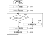
- FIG. 12 is a flowchart showing operational steps during air purifying operation of the dehumidifier 1 of the first embodiment.
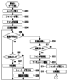
- FIG. 13 is a flowchart showing operation steps during dehumidifying air cleaning operation of the dehumidifier 1 according to the first embodiment.
- the control device 18 controls the inverter circuit 27 for driving the compressor, the louver driving motor 13M of the louver 13, and the motor 21a to all stop. That is, power is not supplied to the compressor motor, the louver drive motor 13M, and the motor 21a. At this time, the louver 13 and the shutter 51s are maintained in a state where the air outlet 12 and the entrance of the bypass air passage 43 are closed, respectively.
- “Dehumidification operation mode” is an operation mode for dehumidifying the room.
- the user can start the operation of the dehumidifier 1 by turning on the operation switch of the input operation section 17 and activating the control device 18.
- the dehumidifier 1 starts dehumidifying operation through the steps shown below.
- control device 18 starts energizing the louver drive motor 13M and controls the position of the louver 13 so that the louver 13 opens the air outlet 12 (step S001).
- louver drive motor 13M For example, a stepping motor is used as the louver drive motor 13M.
- the louver drive motor 13M rotates in a predetermined direction by a constant angle in response to a drive signal from the drive circuit 13A.
- the internal mechanical structure of the louver drive motor 13M enables highly accurate positioning even under open loop control.
- the louver drive motor 13M moves at a step angle in accordance with the number of pulses from the drive circuit 13A. This allows the louver 13 to be maintained open to a specified angle, such as 45 degrees, 60 degrees, or 75 degrees.
- control device 18 controls the position of the shutter 51s by issuing a command signal to the drive circuit 29 so that the shutter 51s opens to the open position, thereby applying drive power to the shutter motor 51m.
- a stepping motor is used as the shutter motor 51m.
- the shutter 51s rotates in a predetermined direction by a constant angle. This rotational movement opens the entrance of the bypass air passage 43 (step S002).
- the shutter 51s When closing the bypass air passage 43, the shutter 51s is in the closed position as shown in FIG. 9. At this time, since the magnet 53a is not located at a position facing the opening/closing detection sensor 53s, the opening/closing detection sensor 53s is in an OFF state. The opening/closing detection sensor 53s emits a signal indicating an OFF state.
- the shutter 51s When opening the bypass air passage 43, the shutter 51s is in the open position as shown in FIG. 10. At this time, since the magnet 53a is in a position opposite to the opening/closing detection sensor 53s, the opening/closing detection sensor 53s is in an ON state. The opening/closing detection sensor 53s emits a signal that is in an ON state. Thereby, the control device 18 can determine that the shutter 51s has reliably opened the bypass air passage 43.
- the shutter 51s rotates in a predetermined direction by a constant angle in response to a drive signal from the drive circuit 29. Therefore, the opening/closing detection section 53 may be omitted.
- the opening/closing detection unit is designed so that the operation can be performed without any abnormality even if there is some kind of defect in this opening/closing. 53 are provided.
- step S002 After determining in step S002 that the shutter 51s is in an open state, the control device 18 drives the motor 21a to control the fan 21 to rotate at a preset strong rotation speed (step S002). S003). It also controls the inverter circuit 27 to drive the compressor. (Step S004).
- the control device 18 uses, for example, the humidity sensor 61 to grasp the humidity.
- the humidity sensor 61 starts an operation of detecting the humidity of the surrounding air and transmits detection data to the control device 18. Thereby, the control device 18 determines whether the humidity is equal to or higher than a threshold value, for example, 50% (step S005).
- Humidity information is an example of environmental information according to the present disclosure. If the humidity is 50% or more, the compressor continues to be driven to perform dehumidifying operation (S006), and after a certain period of time, returns to step S005.
- step S005 if the humidity is lower than 50% as determined in step S005, the control device 18 controls the compressor to stop, and the refrigerant compression operation by the compressor is stopped (step S007). At this time, the control device 18 controls the motor 21a of the fan 21 to continue its rotational driving operation, and returns to step S005 after a certain period of time.
- the humidity detection threshold of the humidity sensor 61 is set to 50%, but the threshold may be any other value.
- the fan 21 is configured to rotate at a preset medium rotation speed instead of a preset high rotation speed. may be controlled. This is because when a filter is not installed, the air volume becomes too large at the same rotation speed as compared to when a filter is installed. In this way, by controlling the fan 21 according to the detection result of the filter detection unit 64, efficient dehumidification is possible.
- the filter detection unit 64 may be configured to be able to detect whether or not both of the two filters are installed, or may be configured to detect either one of them.
- the operation notification unit 15 may notify that the filter is not placed.
- step S002 the shutter 51s may be controlled not to open. That is, when the filter detection unit 64 detects that no filter is installed, it is not necessary to control the opening and closing of the shutter 51s.
- the “air cleaning operation mode” is an operation mode for cleaning indoor air.
- the dehumidifier 1 starts air cleaning operation in the following steps.
- control device 18 sends a start signal to the drive circuit 13A so that the louver 13 opens the air outlet 12, and starts operating the louver drive motor 13M. Then, the louver 13 is opened to a predetermined position (step S101).
- the control device 18 rotates the motor 21a to control the fan 21 to rotate at a preset strong rotation speed (step S102).
- the control device 18 issues measurement commands to the dust sensor 62 and gas sensor 63.
- the dust sensor 62 and the gas sensor 63 each start detecting dust and gas in the air around the sensor and send the detection to the control device 18 .
- the control device 18 determines the level of air pollution from the acquired data (step 103).
- Information indicating the cleanliness of the air acquired by the dust sensor 62 and the gas sensor 63 is an example of environmental information according to the present disclosure.
- step S103 If it is determined in step S103 that the degree of air contamination is small, the control device 18 rotates the fan 21, which is currently being operated at a preset high speed, at a preset low speed. A command to change the rotational speed is issued to the drive circuit 28 (step S104). As a result, air cleaning operation (weak) is performed (step S105), and after a certain period of time, the process returns to step S103.
- step S103 determines whether the air is highly contaminated. If it is determined in step S103 that the air is highly contaminated, the control device 18 performs an air cleaning operation (strong) in which the fan 21 continues to operate at strong rotation (step S106). That is, in this case, the process returns to step S103 after a certain period of time without issuing a command to change the rotation speed to the drive circuit 28.
- strong air cleaning operation
- the operation notification unit 15 may notify that the filter is not placed in step S101. At this time, since the air cannot be purified because no filter is installed, the operation may be stopped. This eliminates wasteful operation and enables efficient operation.
- the dehumidifying air cleaning operation mode automatically switches the operation mode of the dehumidifier 1 to a dehumidifying operation mode, an air cleaning operation mode, or the like, depending on the indoor humidity and air pollution state. For example, when the user turns on the main power switch of the input operation section 17 and selects the dehumidifying air cleaning operation mode with the operation mode changeover switch 17S, the dehumidifier 1 starts the dehumidifying air cleaning operation as follows.
- control device 18 issues a drive command to the drive circuit 28 and controls the louver drive motor 13M so that the louver 13 opens the air outlet 12 (step S201).
- control device 18 issues a drive command to the drive circuit 29 to open the shutter 51s, and controls the shutter motor 51m for opening and closing the shutter 51s. As a result, the entrance of the bypass air passage 43 is opened (step S202).
- control device 18 determines that the shutter 51s has been opened to a predetermined position, it issues a predetermined drive command to the drive circuit 28 in order to rotationally drive the motor 21a.
- the drive circuit 28 controls the rotation speed of the motor 21a so that the fan 21 rotates at a preset high rotation speed (step S203). Further, the control device 18 starts operating the compressor (step S204).
- the humidity sensor 61 starts a humidity detection operation and sends humidity detection data to the control device 18.
- the control device 18 determines whether the humidity is 50% or more (step S205).
- step S206 If the humidity is 50% or higher, continue driving the compressor.
- the dust sensor 62 and the gas sensor 63 start detecting dust and gas in the air around each sensor, and determine the degree of air pollution (step S206). If the degree of air contamination is small, the operations of steps S202, S203, and S204 are continued, and dehumidification operation is performed (step S207). Then, after a certain period of time has passed since step S206, the process returns to step S205.
- control device 18 controls the shutter motor 51m to close the shutter 51s, closes the entrance of the bypass air passage 43 (step S208), and performs a dehumidifying air purification operation (step S209). , after a certain period of time has elapsed from step S206, the process returns to step S205.
- step S205 if the humidity is lower than 50%, the control device 18 controls the compressor to stop driving (step S210).
- control device 18 controls the dust sensor 62 and the gas sensor 63 to start their detection operations, and determines the amount of dirt in the air (step S211).
- step S212 If the degree of air pollution is small, the motor 21a is controlled so that the fan 21 rotates at a preset low rotational speed (step S212), and a circulating operation is performed in which only air is blown without dehumidification (step S213). ), and after a certain period of time, the process returns to step S205.
- the control device 18 issues a closing command signal to the drive circuit 29 to close the shutter 51s.
- the drive circuit 29 starts operating the shutter motor 51m, moves the shutter 51s to the closed position, and the entrance of the bypass air passage 43 is closed (step S214).
- the fan 21 maintains the "strong operation” in step S203 and performs air purifying operation (step S215).
- the process returns to step S005 in the dehumidifying operation mode in FIG.
- the humidity threshold of the humidity sensor 61 in step S205 is set to 50%, but the threshold may be any other value.
- step S203 the fan 21 may be controlled to rotate at a preset medium rotation speed instead of a preset high rotation speed. Further, even if it is detected that the air is highly contaminated in steps S206 and S214, the shutter 51s may not close in steps S208 and S214. At this time, the operation may be stopped because the air cannot be purified. Further, in steps S202, S206, and S214, the flap may not be opened. That is, when the filter detection unit 64 detects that no filter is installed, the shutter 51s may not be controlled to open or close.
- the airflow restricting means 51 for opening and closing the entrance of the bypass air passage 43 is provided, it is possible to select which of the bypass air passage 43 and the main air passage 44 is suitable as an air passage for performing dehumidification operation and air purification operation.
- the dehumidifier 1 can be easily selected and can be easily used and operated efficiently.
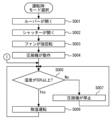
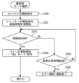
- FIG. 14 is a flowchart showing the basic operation steps of the control device 18 when the dehumidifier 1 of the first embodiment starts operating.
- the user turns on the main power switch using the input operation section 17 and operates the operation mode changeover switch 17S. In this way, an operation mode such as "dehumidification operation” or “air purification operation” is selected.
- control device 18 first checks whether there is any abnormality in its own internal configuration. If there is no abnormality in the initial abnormality determination, a command signal to open the louver 13 is issued to the drive circuit 13A (step S300).
- step S300 the louver 13 is quickly rotated to a predetermined open position by the louver drive motor 13M. Further, the control device 18 issues a command signal to the drive circuit 29 to open the shutter 51s. Then, the timer section 24T starts measuring the elapsed time from this point (step S301).
- the drive circuit 29 starts driving the shutter motor 51m of the airflow restricting means 51.
- the shutter 51s is rotated by a shutter motor 51m to an open position by a range of about 90 degrees about the upper rotation shaft 51a and the lower rotation shaft 51b. As a result, the entrance of the bypass air passage 43 is opened.
- control device 18 waits for the arrival of an open detection signal from the open/close detector 53 and determines whether the entrance of the bypass air passage 43 is opened (step S302). If the determination result in step S302 is "Yes”, a command signal to start blowing air is issued to the drive circuit 28.
- the command regarding the blowing intensity in this case is “strong”, and the fan 21 starts operating in the "strong” operation mode determined by the rated blowing capacity (step S303).
- step S304 if the elapsed time from step S301 does not exceed a predetermined "reference response time", for example, 10 seconds, the process returns to step S302 and the open detection signal from the open/close detector 53 is detected. Determine whether or not it is open or closed based on
- step S304 if the elapsed time from step S301 exceeds the "standard response time", it is determined that an abnormality has occurred in the airflow restricting means 51 for some reason, and the shutter 51s is opened by the notification unit 23. It is notified that it will not be done (step S305).
- the display unit 23D provides notification in text or graphics.
- the audio notification unit 23V may provide a notification such as "the bypass air path does not open properly” or the like. Then, after a certain period of time has elapsed from the time of these notifications, for example, 30 seconds, the main power switch is automatically turned off and the operation is automatically terminated.
- step S305 if the notification unit 23 notifies you to only perform an operation that does not use the bypass air path 43, and no input is made from the input operation unit 17 after that, the process will proceed as in step S305.
- the power may be automatically shut off.
- a shutter 51s is installed in each of the plurality of bypass air passages 43. If a shutter 51s that does not open or close in response to an instruction from the control device 18 is included among the plurality of shutters 51s, an abnormality of the shutter 51s is notified, that is, which shutter 51s has an abnormality. It may be configured as follows.
- the airflow restricting means 51 is configured to open and close the shutter 51s in response to an electric signal. Therefore, there is no need for the user to manually open and close the shutter 51s, and the burden on the user associated with the dehumidifying operation can be reduced.
- the attachment/detachment status of the filter can be detected, the operating status of the fan 21 can be appropriately controlled depending on whether the filter is installed or not, and efficient operation is possible. Furthermore, since it is possible to notify whether a filter is installed or not, it is possible to prevent forgetting to attach a filter. Furthermore, during the air cleaning operation and the dehumidifying air cleaning operation, it is also possible to notify that the air cannot be cleaned if a filter is not placed.
- the shutter motor 51m is arranged inside the upper wall of the bypass air passage 43, and the opening/closing detection sensor 53s is arranged inside the lower wall, making the structure of the dehumidifier 1 compact and simple. can. Further, the shutter 51s can be opened and closed reliably.
- the dehumidifier according to the present disclosure can be used, for example, to dehumidify indoor air.
Landscapes
- Engineering & Computer Science (AREA)
- Chemical & Material Sciences (AREA)
- Combustion & Propulsion (AREA)
- Mechanical Engineering (AREA)
- General Engineering & Computer Science (AREA)
- Drying Of Gases (AREA)
Priority Applications (2)
| Application Number | Priority Date | Filing Date | Title |
|---|---|---|---|
| JP2024520147A JP7632748B2 (ja) | 2022-05-11 | 2022-05-11 | 除湿機 |
| PCT/JP2022/019969 WO2023218565A1 (ja) | 2022-05-11 | 2022-05-11 | 除湿機 |
Applications Claiming Priority (1)
| Application Number | Priority Date | Filing Date | Title |
|---|---|---|---|
| PCT/JP2022/019969 WO2023218565A1 (ja) | 2022-05-11 | 2022-05-11 | 除湿機 |
Publications (1)
| Publication Number | Publication Date |
|---|---|
| WO2023218565A1 true WO2023218565A1 (ja) | 2023-11-16 |
Family
ID=88730050
Family Applications (1)
| Application Number | Title | Priority Date | Filing Date |
|---|---|---|---|
| PCT/JP2022/019969 Ceased WO2023218565A1 (ja) | 2022-05-11 | 2022-05-11 | 除湿機 |
Country Status (2)
| Country | Link |
|---|---|
| JP (1) | JP7632748B2 (enExample) |
| WO (1) | WO2023218565A1 (enExample) |
Families Citing this family (1)
| Publication number | Priority date | Publication date | Assignee | Title |
|---|---|---|---|---|
| JP7666398B2 (ja) * | 2022-05-13 | 2025-04-22 | 三菱電機株式会社 | 除湿機 |
Citations (4)
| Publication number | Priority date | Publication date | Assignee | Title |
|---|---|---|---|---|
| JP2000055424A (ja) * | 1998-08-04 | 2000-02-25 | Sanyo Electric Co Ltd | 空気清浄機 |
| JP2004077082A (ja) * | 2002-08-21 | 2004-03-11 | Daikin Ind Ltd | 換気装置 |
| JP2004211913A (ja) * | 2002-12-26 | 2004-07-29 | Sanyo Electric Co Ltd | 除湿機 |
| JP2021085555A (ja) * | 2019-11-25 | 2021-06-03 | シャープ株式会社 | フィルタ検知装置、空気調和機 |
-
2022
- 2022-05-11 JP JP2024520147A patent/JP7632748B2/ja active Active
- 2022-05-11 WO PCT/JP2022/019969 patent/WO2023218565A1/ja not_active Ceased
Patent Citations (4)
| Publication number | Priority date | Publication date | Assignee | Title |
|---|---|---|---|---|
| JP2000055424A (ja) * | 1998-08-04 | 2000-02-25 | Sanyo Electric Co Ltd | 空気清浄機 |
| JP2004077082A (ja) * | 2002-08-21 | 2004-03-11 | Daikin Ind Ltd | 換気装置 |
| JP2004211913A (ja) * | 2002-12-26 | 2004-07-29 | Sanyo Electric Co Ltd | 除湿機 |
| JP2021085555A (ja) * | 2019-11-25 | 2021-06-03 | シャープ株式会社 | フィルタ検知装置、空気調和機 |
Also Published As
| Publication number | Publication date |
|---|---|
| JP7632748B2 (ja) | 2025-02-19 |
| JPWO2023218565A1 (enExample) | 2023-11-16 |
Similar Documents
| Publication | Publication Date | Title |
|---|---|---|
| EP2088382A1 (en) | Air conditioner | |
| CN111189119B (zh) | 空气处理装置、空调室内机及空调器 | |
| JP2024079784A (ja) | 除湿機 | |
| JP4417709B2 (ja) | 空気調和機 | |
| JP7632748B2 (ja) | 除湿機 | |
| JP2008196715A (ja) | 空気調和装置 | |
| JP7452765B2 (ja) | 空気調和機または空気清浄機または除湿空清機 | |
| KR100845836B1 (ko) | 환기장치 및 환기장치의 운영방법 | |
| CN114270103B (zh) | 空调机 | |
| CN215809064U (zh) | 一种新风机及机柜 | |
| JP7622817B2 (ja) | 除湿機 | |
| CN118318131A (zh) | 空气处理装置 | |
| JP7666398B2 (ja) | 除湿機 | |
| JP7694823B2 (ja) | 除湿機 | |
| JP7668543B2 (ja) | 空気調和装置 | |
| HK40090311B (zh) | 除湿机 | |
| HK40090311A (zh) | 除湿机 | |
| TWI836819B (zh) | 除濕機 | |
| JP2023167895A (ja) | 除湿機 | |
| JP2012097999A (ja) | 空気調和機 | |
| JP2001116333A (ja) | 空気調和機 | |
| JP2025174594A (ja) | 空気調和装置及び衣類乾燥方法 | |
| JP2025135302A (ja) | 空気調和装置 | |
| JP2008014608A (ja) | 床置き空気調和装置 |
Legal Events
| Date | Code | Title | Description |
|---|---|---|---|
| 121 | Ep: the epo has been informed by wipo that ep was designated in this application |
Ref document number: 22941645 Country of ref document: EP Kind code of ref document: A1 |
|
| ENP | Entry into the national phase |
Ref document number: 2024520147 Country of ref document: JP Kind code of ref document: A |
|
| NENP | Non-entry into the national phase |
Ref country code: DE |
|
| 122 | Ep: pct application non-entry in european phase |
Ref document number: 22941645 Country of ref document: EP Kind code of ref document: A1 |