WO2023218565A1 - Dehumidifier - Google Patents
Dehumidifier Download PDFInfo
- Publication number
- WO2023218565A1 WO2023218565A1 PCT/JP2022/019969 JP2022019969W WO2023218565A1 WO 2023218565 A1 WO2023218565 A1 WO 2023218565A1 JP 2022019969 W JP2022019969 W JP 2022019969W WO 2023218565 A1 WO2023218565 A1 WO 2023218565A1
- Authority
- WO
- WIPO (PCT)
- Prior art keywords
- airflow
- air
- opening
- dehumidifier
- closing
- Prior art date
Links
- 238000001514 detection method Methods 0.000 claims abstract description 75
- 238000007664 blowing Methods 0.000 claims abstract description 15
- 239000003507 refrigerant Substances 0.000 claims abstract description 15
- 238000004887 air purification Methods 0.000 claims abstract description 10
- 239000000428 dust Substances 0.000 claims description 23
- 230000004044 response Effects 0.000 claims description 11
- 230000005856 abnormality Effects 0.000 claims description 8
- 230000007613 environmental effect Effects 0.000 claims description 6
- 230000003749 cleanliness Effects 0.000 claims description 3
- 238000009434 installation Methods 0.000 claims 2
- 238000007791 dehumidification Methods 0.000 abstract description 17
- OKTJSMMVPCPJKN-UHFFFAOYSA-N Carbon Chemical compound [C] OKTJSMMVPCPJKN-UHFFFAOYSA-N 0.000 description 46
- 238000004140 cleaning Methods 0.000 description 16
- 238000000034 method Methods 0.000 description 10
- 230000008569 process Effects 0.000 description 10
- 238000004891 communication Methods 0.000 description 8
- 238000010586 diagram Methods 0.000 description 6
- 230000001105 regulatory effect Effects 0.000 description 6
- XLYOFNOQVPJJNP-UHFFFAOYSA-N water Substances O XLYOFNOQVPJJNP-UHFFFAOYSA-N 0.000 description 5
- 238000003915 air pollution Methods 0.000 description 4
- 230000001276 controlling effect Effects 0.000 description 4
- 230000008859 change Effects 0.000 description 3
- 235000019645 odor Nutrition 0.000 description 3
- 238000011144 upstream manufacturing Methods 0.000 description 3
- 238000011109 contamination Methods 0.000 description 2
- 235000014676 Phragmites communis Nutrition 0.000 description 1
- 230000003213 activating effect Effects 0.000 description 1
- 230000006835 compression Effects 0.000 description 1
- 238000007906 compression Methods 0.000 description 1
- 230000008878 coupling Effects 0.000 description 1
- 238000010168 coupling process Methods 0.000 description 1
- 238000005859 coupling reaction Methods 0.000 description 1
- 230000007547 defect Effects 0.000 description 1
- 230000000694 effects Effects 0.000 description 1
- 230000005611 electricity Effects 0.000 description 1
- 239000000835 fiber Substances 0.000 description 1
- 230000010365 information processing Effects 0.000 description 1
- 230000005389 magnetism Effects 0.000 description 1
- 239000000463 material Substances 0.000 description 1
- 238000005259 measurement Methods 0.000 description 1
- 239000002184 metal Substances 0.000 description 1
- 238000000465 moulding Methods 0.000 description 1
- 239000002245 particle Substances 0.000 description 1
- 230000002093 peripheral effect Effects 0.000 description 1
- 230000001681 protective effect Effects 0.000 description 1
- 238000005057 refrigeration Methods 0.000 description 1
- 238000009423 ventilation Methods 0.000 description 1
Images


Classifications
-
- F—MECHANICAL ENGINEERING; LIGHTING; HEATING; WEAPONS; BLASTING
- F24—HEATING; RANGES; VENTILATING
- F24F—AIR-CONDITIONING; AIR-HUMIDIFICATION; VENTILATION; USE OF AIR CURRENTS FOR SCREENING
- F24F1/00—Room units for air-conditioning, e.g. separate or self-contained units or units receiving primary air from a central station
- F24F1/02—Self-contained room units for air-conditioning, i.e. with all apparatus for treatment installed in a common casing
- F24F1/0328—Self-contained room units for air-conditioning, i.e. with all apparatus for treatment installed in a common casing with means for purifying supplied air
- F24F1/035—Self-contained room units for air-conditioning, i.e. with all apparatus for treatment installed in a common casing with means for purifying supplied air characterised by the mounting or arrangement of filters
-
- F—MECHANICAL ENGINEERING; LIGHTING; HEATING; WEAPONS; BLASTING
- F24—HEATING; RANGES; VENTILATING
- F24F—AIR-CONDITIONING; AIR-HUMIDIFICATION; VENTILATION; USE OF AIR CURRENTS FOR SCREENING
- F24F1/00—Room units for air-conditioning, e.g. separate or self-contained units or units receiving primary air from a central station
- F24F1/02—Self-contained room units for air-conditioning, i.e. with all apparatus for treatment installed in a common casing
- F24F1/0358—Self-contained room units for air-conditioning, i.e. with all apparatus for treatment installed in a common casing with dehumidification means
-
- F—MECHANICAL ENGINEERING; LIGHTING; HEATING; WEAPONS; BLASTING
- F24—HEATING; RANGES; VENTILATING
- F24F—AIR-CONDITIONING; AIR-HUMIDIFICATION; VENTILATION; USE OF AIR CURRENTS FOR SCREENING
- F24F2130/00—Control inputs relating to environmental factors not covered by group F24F2110/00
- F24F2130/20—Sunlight
Definitions
- the present disclosure relates to a dehumidifier.
- a dehumidifier is described in Patent Document 1.
- the dehumidifier shown in Patent Document 1 dehumidifies air taken in from an intake port by passing it through a heat exchanger.
- the filter is arranged between the air intake port and the heat exchanger so as not to cover the front side of the heat exchanger, that is, a portion of the upstream side of the airflow when viewed from the heat exchanger.
- a shutter is provided to block air flow. The shutter is selectively provided in a position where it covers a portion of the passage to the heat exchanger and a position where it does not cover the passage.
- An object of the present disclosure is to provide a dehumidifier that can be operated efficiently.
- the dehumidifier according to the present disclosure includes a casing in which an inlet and an outlet are formed, a blowing means for generating an airflow from the inlet to the outlet, and a dehumidifier that is disposed inside the casing and is detachable.
- the dehumidifier includes an air purifying means provided in the casing, and a dehumidifying means disposed inside the casing to remove moisture from the airflow.
- This dehumidifier includes a first air path formed inside the housing, through which the airflow passes through the air purifying means, and reaches the dehumidification means; a second air path leading to the dehumidifying means without passing through the air purifying means; an air flow restricting means for restricting airflow flowing through the second air path; and a compressor for supplying refrigerant to the dehumidifying means.
- a control device for controlling the air blowing means, the air flow restricting means, and the compressor, and an attachment/detachment detection means for detecting the attachment/detachment state of the air purifying means. The control device controls the air blower according to the detection result of the attachment/detachment detection means.
- the dehumidifier includes a casing in which an inlet and an outlet are formed, a blower for generating an airflow from the inlet to the outlet, and disposed inside the casing,
- the dehumidifier includes an air purifying means that is detachably provided, and a dehumidifying means that is disposed inside the housing and removes moisture from the airflow.
- This dehumidifier includes a first air path formed inside the housing, through which the airflow passes through the air purifying means, and reaches the dehumidification means; Selecting a second air path that reaches the dehumidifying means without passing through the air purifying means, a state in which the air flow in the second air path is allowed to pass, and a state in which the air flow in the second air path is blocked.
- a compressor that supplies refrigerant to the dehumidifying means; and a control device that controls the blowing means, the opening and closing means, and the compressor.
- the opening/closing means is disposed within the second air path and is supported by two shafts in the vertical direction of the housing.
- a motor with a position control function is connected to one side of the two shafts, and an opening/closing detection means for detecting whether the opening/closing means is open or closed is provided on the other side.
- FIG. 2 is a perspective view of the dehumidifier of Embodiment 1 seen from the front side.
- FIG. 2 is a perspective view of the dehumidifier of Embodiment 1 seen from the back side.
- 2 is a vertical cross-sectional view taken along line AA shown in FIG. 1.
- FIG. 2 is a horizontal cross-sectional view taken along line BB shown in FIG. 1.
- FIG. FIG. 2 is a block diagram showing the main control configuration of the dehumidifier according to the first embodiment.
- FIG. 2 is a perspective view of the dehumidifier of Embodiment 1 with the suction port cover, HEPA filter, and activated carbon filter removed, as seen from the back side.
- FIG. 3 is a schematic diagram for easily explaining the flow of air in the first embodiment.
- FIG. 1 is a simplified diagram showing the configuration of a shutter in Embodiment 1.
- FIG. FIG. 2 is a cross-sectional view of a main part when a shutter is shielding a bypass air path in Embodiment 1;
- FIG. 2 is a sectional view of a main part when the shutter opens a bypass air path in the first embodiment.
- 5 is a flowchart showing operational steps during dehumidifying operation of the dehumidifier of Embodiment 1.
- FIG. 3 is a flowchart showing operational steps during air purifying operation of the dehumidifier of Embodiment 1.
- FIG. 2 is a flowchart showing operational steps during dehumidifying air cleaning operation of the dehumidifier of the first embodiment.
- 3 is a flowchart showing the basic operation steps of the control device when starting the operation of the dehumidifier according to the first embodiment.
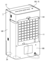
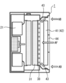
- FIG. 1 is a perspective view of a dehumidifier 1 according to the first embodiment seen from the front side.
- FIG. 2 is a perspective view of the dehumidifier 1 according to the first embodiment, viewed from the back side.
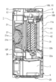
- FIG. 3 is a vertical cross-sectional view taken along line AA shown in FIG.
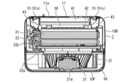
- FIG. 4 is a horizontal cross-sectional view taken along line BB shown in FIG.
- FIG. 5 is a block diagram showing the main control configuration of the dehumidifier according to the first embodiment.
- the dehumidifier 1 will be described based on the state in which the dehumidifier 1 is placed on a horizontal surface such as a floor surface.
- the dehumidifier 1 includes a front case 10F and a rear case 10B.
- the front case 10F and the rear case 10B are members that constitute a casing that forms the outer shell of the dehumidifier 1.
- the housing of the dehumidifier 1 has a bottom plate 4 to which a plurality of wheels 20 are attached.
- the front case 10F, the rear case 10B, and the bottom plate 4 constitute a hollow box-shaped casing.
- a plurality of wheels 20 for moving the dehumidifier 1 are attached to the bottom plate 4.
- the plurality of wheels 20 are arranged one each at positions apart from each other in the front, back, left and right, that is, a total of four wheels 20 are arranged.
- a heavy object such as a compressor is placed on the bottom plate 4. Note that in the present disclosure, illustration of the compressor is omitted for clarity and simplification of the description of the drawings.
- the front case 10F and the rear case 10B are assembled into one box shape by being connected with a coupling device such as a screw, for example.
- the front case 10F is a member that forms the front part of the dehumidifier 1.
- the rear case 10B is a member that forms the back part of the dehumidifier 1.
- a flat upper case 10U is connected to the upper ends of the front case 10F and the rear case 10B.
- a louver 13 is provided at the front of the upper case 10U.
- the upper case 10U and the louver 13 are arranged so as to face each other and come into contact with each other from the front and rear.
- the louver 13 in the closed state forms one flat surface together with the upper case 10U. This surface is the top surface of the casing of the dehumidifier 1.
- a suction port 11 and an air outlet 12 are formed in the casing of the dehumidifier 1.
- the suction port 11 is an opening for taking air into the dehumidifier 1 from the outside.
- the air outlet 12 is an opening for sending air from the inside of the dehumidifier 1 to the outside.
- the suction port 11 is formed as a square window-shaped opening in the center of the rear case 10B.
- the air outlet 12 is formed on the top surface of the dehumidifier 1.
- a louver 13 is arranged at a location where the air outlet 12 is formed. The air outlet 12 is opened by opening the louver 13 upward to a certain angle.
- the suction port 11 has a square shape when the dehumidifier 1 is viewed from the back side.
- the shape of this suction port 11 is not limited to this example, and may be rectangular or circular, for example.
- the dehumidifier 1 includes a suction port cover 11a that covers the suction port 11.
- the suction port cover 11a is a member that prevents foreign matter from entering the inside of the dehumidifier 1 through the suction port 11.
- the suction port cover 11a prevents foreign matter, such as paper scraps and fiber scraps, which are thrown into the air, from entering the inside of the dehumidifier 1, for example.
- the suction port cover 11a is detachably fixed to the rear case 10B.
- the suction port cover 11a is formed, for example, in a grid shape.
- the suction port cover 11a may be formed into a shutter shape, for example.
- a net may be attached to the entire surface of the suction port cover 11a to prevent foreign matter from entering.
- the suction port cover 11a may be formed as a net-shaped member by integral molding of a plastic material.
- the dehumidifier 1 includes a compressor (not shown).
- the compressor may be of any type, such as a reciprocating type or a rotary type.
- the compressor has a motor and circulates refrigerant through the refrigerant pipe 22 connected to the evaporator 31, the first condenser 32a, and the second condenser 32b.
- the compressor is connected to an evaporator 31, a first condenser 32a, a second condenser 32b, and a pressure reducing device (not shown) through a refrigerant pipe 22 to form a refrigerant circuit using a refrigeration cycle.
- the compressor compresses and supplies refrigerant to the refrigerant circuit.
- the evaporator 31, the first condenser 32a, and the second condenser 32b are heat exchangers for exchanging heat between the refrigerant and air.
- a pressure reducing device is a device that reduces the pressure of a refrigerant.
- the pressure reducing device is, for example, an expansion valve or a capillary tube.
- the dehumidifier 1 includes a water storage tank 7. Drain water generated on the external surface of the evaporator 31 during the dehumidifying operation is dripped and guided to the water storage tank 7 .
- the water storage tank 7 can be taken out from an outlet formed in the front case 10F.
- the louver 13 is composed of a single plate-shaped member or a plurality of plate-shaped members.
- the louver 13 is for adjusting the direction in which air is sent out from the air outlet 12, and is installed so as to be openable and closable.
- louver driving motor 13M shown in FIG. 5 is connected to the louver 13.
- the posture of the louver 13 is changed by this louver drive motor 13M.
- the louver drive motor 13M allows the louver 13 to change its inclination angle with respect to the air outlet 12 in several stages. Thereby, the direction of air blown out from the air outlet 12 can be adjusted.
- louver drive motor 13M The operation of the louver drive motor 13M is controlled by a drive signal from a drive circuit 13A mounted on a control board (not shown).
- the control board is housed in a board box 16 formed as a case made of metal or nonflammable heat-resistant plastic.
- control board includes an inverter circuit 27 for driving the compressor, and a drive circuit 28 for driving the fan 21, which will be described later.
- the dehumidifier 1 includes an operation notification section 15.
- the operation notification section 15 includes an input operation section 17 for the user to operate the dehumidifier 1, and a notification section 23 for making various notifications.
- the notification unit 23 displays, for example, the status of the dehumidifier 1 and the like using visible information such as characters. Further, the notification unit 23 may also be capable of providing audio notification.
- the operation notification section 15 is arranged on the top of the dehumidifier 1.
- An operation display board 8 for controlling the operation notification section 15 is arranged inside the upper case 10U so as to face the operation notification section 15.
- An operation switch for starting and stopping the operation of the dehumidifier 1 is arranged in the input operation section 17.
- the input operation unit 17 is an operation mode for switching the operation mode of the dehumidifier 1 to any one of three types: "dehumidification operation mode”, “air purification operation mode”, and “dehumidification air purification operation mode”. It has a changeover switch 17S.
- a fan 21 is housed inside the dehumidifier 1.
- the fan 21 is a device that takes air into the dehumidifier 1 and sends the taken air to the outside of the dehumidifier 1.
- the fan 21 generates an airflow from the suction port 11 to the blowout port 12 in an air path from the suction port 11 to the blowout port 12 by rotating.
- a motor 21a is housed inside the dehumidifier 1.
- the motor 21a is a device that rotates the fan 21.
- fan 21 and motor 21a are arranged on the front side of dehumidifier 1.
- the motor 21a is connected to the rotation center of the fan 21 via a rotation shaft 21b extending in the horizontal direction.
- the fan 21 and the motor 21a constitute an example of a blowing means that generates an airflow from the suction port 11 to the blowout port 12.
- the start of rotation, the stop of rotation, and the rotation speed of the motor 21a are controlled by a drive circuit 28.
- the fan 21 is, for example, a sirocco fan.
- the center of rotation of the fan 21 is fixed by a rotating shaft 21b.
- the fan 21 sucks air into the fan case 36 from the front and blows the air out from the air outlet 12.
- the fan case 36 surrounds the fan 21 and the motor 21a.
- a bell mouth portion 37 is formed on the front wall surface of the fan case 36 at a position corresponding to the fan 21.
- This bell mouth portion 37 is a large circular opening, and its mouth edge is largely curved toward the leeward side.
- the bell mouth portion 37 is configured to smoothly suck in the airflow that has passed through the first condenser 32a.
- the dehumidifier 1 of the present embodiment includes an evaporator 31, a first condenser 32a, and a second condenser 32b as an example of a dehumidifying means for removing moisture in the airflow from the suction port 11 to the blowout port 12. .
- the evaporator 31, the first condenser 32a, and the second condenser 32b are housed inside the casing of the dehumidifier 1. As shown in FIG. 4, the evaporator 31, the first condenser 32a, and the second condenser 32b are each installed vertically so as to close the front side of the bell mouth portion 37.
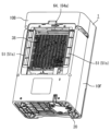
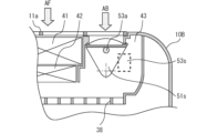
- FIG. 6 is a perspective view of the dehumidifier 1 according to the first embodiment, with the suction port cover 11a, HEPA filter 41, and activated carbon filter 42 removed, as seen from the back side.
- the dehumidifier 1 includes a flow regulating member 38.
- the flow regulating member 38 is formed from a frame-shaped member that intersects in the vertical direction and the horizontal direction, and a large number of ventilation windows are formed between each frame. In other words, this rectifying member 38 forms a grid-like member.
- the rectifying member 38 faces the rear surface of the evaporator 31 with a first space in between. That is, the rectifying member 38 faces the evaporator 31 at a predetermined distance.
- this rectifying member 38 faces the front surface of the activated carbon filter 42 with a second space in between. That is, the rectifying member 38 faces the front surface of the activated carbon filter 42 with a predetermined distance therebetween.
- the dehumidifier 1 of this embodiment includes a HEPA filter 41 and an activated carbon filter 42, which are air purifying filters for purifying the air, as an example of air purifying means for removing dust, odor, etc. from the air.
- HEPA filter 41 and activated carbon filter 42 are housed inside rear case 10B.
- the HEPA filter 41 is a filter that collects fine dust in the air.
- HEPA filter 41 is an example of a first filter that collects dust from airflow.
- the activated carbon filter 42 is a filter that deodorizes the air.
- Activated carbon filter 42 is an example of a second filter that removes odors from the airflow. As described above, the activated carbon filter 42 is placed a predetermined distance apart from the rear surface of the flow regulating member 38.
- the HEPA filter 41 and activated carbon filter 42 can be inserted up to the rear position of the flow regulating member 38 with the suction port cover 11a removed from the rear case 10B.
- the HEPA filter 41 and the activated carbon filter 42 can be detachably installed inside the rear case 10B.
- a filter detection section 64 is provided in the rear case 10B as an example of an attachment/detachment means for detecting the attachment/detachment state of a filter, which is an air purifying means.
- the filter detection unit 64 includes a detection lever 64a that is pressed down by the edge of the HEPA filter 41 and a detection switch. The detection lever 64a is pressed down when the HEPA filter 41 is installed, and when the detection lever 64a is pressed down, the detection switch is pressed and turned on. The ON state and OFF state of the detection switch can be determined by the presence or absence of an electric signal.
- the rectifying member 38 also serves as a protective member to prevent the user from touching the evaporator 31 when the HEPA filter 41 and activated carbon filter 42 are removed from the rear case 10B. For example, even if a user pushes the rectifying member 38 from the front with a finger or the like, the finger or the like will not touch the evaporator 31.
- an air path leading from the suction port 11 to the outlet 12 is formed inside the dehumidifier 1.
- the airflow flowing inside the air passage passes through the suction port 11, the suction port cover 11a, the HEPA filter 41, the activated carbon filter 42, the evaporator 31, the second condenser 32b, the first condenser 32a, and the fan 21 in this order.
- a series of air passages are formed through which air entering from the suction port 11 passes through a filter, which is an air purifying means, and flows from each heat exchanger toward the fan 21.
- the upstream side and the downstream side are defined using the airflow flowing through the air path leading from the inlet 11 to the outlet 12.
- the side where the suction port 11 is located with respect to the heat exchanger such as the evaporator 31 is defined as the upstream side.
- the side where the air outlet 12 is located with respect to the heat exchanger such as the evaporator 31 is defined as the downstream side.
- the dehumidifier 1 includes a dust sensor 62.
- This dust sensor 62 is arranged inside the dehumidifier 1.
- a small opening is provided near the dust sensor 62 so that the dust sensor 62 communicates with the outside of the dehumidifier 1.
- Dust sensor 62 and control device 18 can acquire dust detection information.
- the dust sensor 62 and the control device 18 can measure the amount and concentration of dust in the indoor space where the dehumidifier 1 is installed.
- the dust sensor 62 has the ability to detect particles of 0.1 ⁇ m, for example.
- the detection result of the dust sensor 62 is acquired by the control device 18, and the acquired dust detection information can be displayed on the operation notification section 15.
- the dehumidifier 1 includes a gas sensor 63.
- This gas sensor 63 is arranged inside the dehumidifier 1, and a small opening is provided near the gas sensor 63 so that the gas sensor 63 communicates with the outside of the dehumidifier 1.
- Gas detection information is acquired by the gas sensor 63 and the control device 18, and the odor of indoor air can be measured.
- the detection result of the gas sensor 63 is acquired by the control device 18, and the acquired gas detection information can be displayed on the operation notification section 15.
- the dehumidifier 1 includes a wireless communication section 26.
- the wireless communication unit 26 is housed near the ceiling inside the upper case 10U.
- the wireless communication unit 26 is capable of wireless communication with local network equipment such as a wireless router installed in the home or office where the dehumidifier 1 is located.
- the wireless communication unit 26 may be connected to the Internet line via local network equipment.
- the wireless communication unit 26 can exchange information with an information processing terminal such as a smartphone and other communication devices located at a remote location via an Internet line.
- the local network equipment may be a command device that controls the total amount of electricity used in a home or office, or an integrated management device that collects and coordinates information on multiple electrical devices. Also called "point".
- bypass air passages 43 adjacent to the left and right sides of the HEPA filter 41 and the activated carbon filter 42.
- the bypass air passage 43 is a space provided throughout the height direction of the suction port 11 inside the rear case 10B.
- the bypass air path 43 is an air path that extends forward from the suction port 11.
- the bypass air passage 43 is a narrow space extending from the rear to the front.
- the bypass air passage 43 is an air passage sandwiched between a bypass air passage outer wall 43a and a filter case outer wall 43b.
- the gap between the rear end of the bypass air passage outer wall 43a and the rear end of the filter case outer wall 43b serves as an entrance to the bypass air passage 43.
- the front end of the bypass air passage outer wall 43a is in contact with the outer peripheral end of the flow regulating member 38, so that airflow does not leak outside in the middle of the bypass air passage 43.
- a gap between the front end of the bypass air passage outer wall 43a and the front end of the filter case outer wall 43b serves as an outlet of the bypass air passage 43.
- the air passage leading from the inlet 11 to the outlet 12 includes two air passages: a main air passage 44 that is a first air passage and a bypass air passage 43 that is a second air passage. It is configured.
- the main air passage 44 is an air passage that extends from the suction port 11 through the HEPA filter 41 and the activated carbon filter 42 and reaches the flow regulating member 38.
- the bypass air passage 43 is an air passage from the suction port 11 to the rectifying member 38 without passing through the HEPA filter 41 and the activated carbon filter 42 .
- the main air passage 44 and the bypass air passage 43 join immediately before the flow straightening member 38.
- the dehumidifier 1 includes an airflow restriction means 51 for substantially opening and closing the inlet of the bypass airway 43 to restrict the airflow flowing through the bypass airway 43.
- the airflow restricting means 51 are arranged on the left and right sides of the suction port 11, respectively. Note that as the configuration of the airflow restricting means 51, any configuration can be adopted as long as it is capable of restricting the airflow flowing through the bypass air path 43.
- a configuration will be described in which a shutter 51s, which is an opening/closing means, is adopted.
- FIG. 7 is a schematic diagram for easily explaining the flow of air in the first embodiment.
- the bypass air passage 43 is an air passage through which the air flow AB flows downstream without passing through the HEPA filter 41 and the activated carbon filter 42.
- a main air path 44 is an air path through which the airflow AF passes through the HEPA filter 41 and the activated carbon filter 42.
- bypass air passages 43 are formed on the right and left sides of the HEPA filter 41 and activated carbon filter 42, respectively.
- the bypass air passage 43 and the main air passage 44 are arranged adjacent to each other on the left and right in parallel.
- the airflow AB passing through the bypass air passage 43 and the airflow AF passing through the main air passage 44 do not merge inside the HEPA filter 41 and the activated carbon filter 42.
- the air path inside the dehumidifier 1 is improved.
- the air path inside the dehumidifier 1 is improved.
- the vertical height of the bypass air passage 43 is set to be approximately the same as the length of the HEPA filter 41 in the vertical direction.
- the bypass airflow AB flowing in the bypass airflow path 43 and the main airflow AF flowing in the main airflow path 44 are connected to a space downstream of the activated carbon filter 42, that is, a first space a certain distance apart from the rectification member 38 as a starting point, and a rectification. Starting from the member 38, it merges with a second space spaced a certain distance apart.
- the bypass airflow AB and the main airflow AF merge before the evaporator 31 located downstream of the activated carbon filter 42, and thereafter flow in one air path.
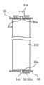
- FIG. 8 is a simplified diagram showing the configuration of the shutter 51s of the first embodiment.
- FIG. 9 is a sectional view of a main part when the shutter 51s is shielding the bypass air passage 43 in the first embodiment.
- FIG. 10 is a sectional view of a main part when the shutter 51s opens the bypass air passage 43 in the first embodiment.
- the shutter 51s is provided in the bypass air passage 43.
- the shutter 51s is supported by two shafts in the vertical direction of the casing of the dehumidifier 1.
- the shutter 51s has an upper rotation shaft 51a and a lower rotation shaft 51b.
- the upper bypass wall 65 and lower bypass wall 66 of the bypass air passage 43 are provided with an upper bearing 65a and a lower bearing 66a, respectively.
- the upper rotation shaft 51a and the lower rotation shaft 51b of the shutter 51s are inserted into the upper bearing 65a and the lower bearing 66a, respectively, so that the shutter 51s is rotatable.
- a shutter motor 51m is arranged inside the bypass upper wall 65 of the bypass air passage 43.
- the upper rotating shaft 51a of the shutter 51s is connected to the rotating shaft of the shutter motor 51m.
- the shutter motor 51m is a motor with a position control function. By controlling the rotational position of the shutter motor 51m, the shutter 51s can be moved to a position where the airflow in the bypass air path 43 is blocked, as shown in FIG. 9, and a position where the airflow is allowed to pass through the bypass air path 43, as shown in FIG. It rotates between .
- the shutter 51s can select between a state in which the airflow in the bypass air path 43, which is the second air path, is allowed to pass through and a state in which the airflow in the bypass air path 43 is blocked.
- the shutter 51s is provided with an opening/closing detection section 53 as an opening/closing detection means for detecting whether the shutter 51s is in an open state or a closed state.
- an opening/closing detection section 53 can be configured arbitrarily, the opening/closing detection sensor 53s will be described here as an example.
- An opening/closing detection sensor 53s is arranged inside the bypass lower wall 66 of the bypass air passage 43. The opening/closing detection sensor 53s detects magnetism to turn ON/OFF a signal, and can use, for example, a Hall IC or a reed switch.
- a magnet 53a is installed on the wall surface of the lower end of the shutter 51s.
- a magnet 53a is installed at a position facing the opening/closing detection sensor 53s when the shutter 51s is in a position to open the bypass air passage 43.
- the opening/closing detection sensor 53s detects the magnet 53a, thereby making it possible to determine whether the bypass air passage 43 is open.
- the shutter motor 51m is arranged inside the bypass upper wall 65 of the bypass air passage 43, and the opening/closing detection sensor 53s is arranged inside the bypass lower wall 66, resulting in a compact and simple structure.
- the shutter motor 51m and the opening/closing detection sensor 53s are configured to face each other.
- FIG. 11 is a flowchart showing operation steps during dehumidifying operation of the dehumidifier 1 of the first embodiment.
- FIG. 12 is a flowchart showing operational steps during air purifying operation of the dehumidifier 1 of the first embodiment.
- FIG. 13 is a flowchart showing operation steps during dehumidifying air cleaning operation of the dehumidifier 1 according to the first embodiment.
- the control device 18 controls the inverter circuit 27 for driving the compressor, the louver driving motor 13M of the louver 13, and the motor 21a to all stop. That is, power is not supplied to the compressor motor, the louver drive motor 13M, and the motor 21a. At this time, the louver 13 and the shutter 51s are maintained in a state where the air outlet 12 and the entrance of the bypass air passage 43 are closed, respectively.
- “Dehumidification operation mode” is an operation mode for dehumidifying the room.
- the user can start the operation of the dehumidifier 1 by turning on the operation switch of the input operation section 17 and activating the control device 18.
- the dehumidifier 1 starts dehumidifying operation through the steps shown below.
- control device 18 starts energizing the louver drive motor 13M and controls the position of the louver 13 so that the louver 13 opens the air outlet 12 (step S001).
- louver drive motor 13M For example, a stepping motor is used as the louver drive motor 13M.
- the louver drive motor 13M rotates in a predetermined direction by a constant angle in response to a drive signal from the drive circuit 13A.
- the internal mechanical structure of the louver drive motor 13M enables highly accurate positioning even under open loop control.
- the louver drive motor 13M moves at a step angle in accordance with the number of pulses from the drive circuit 13A. This allows the louver 13 to be maintained open to a specified angle, such as 45 degrees, 60 degrees, or 75 degrees.
- control device 18 controls the position of the shutter 51s by issuing a command signal to the drive circuit 29 so that the shutter 51s opens to the open position, thereby applying drive power to the shutter motor 51m.
- a stepping motor is used as the shutter motor 51m.
- the shutter 51s rotates in a predetermined direction by a constant angle. This rotational movement opens the entrance of the bypass air passage 43 (step S002).
- the shutter 51s When closing the bypass air passage 43, the shutter 51s is in the closed position as shown in FIG. 9. At this time, since the magnet 53a is not located at a position facing the opening/closing detection sensor 53s, the opening/closing detection sensor 53s is in an OFF state. The opening/closing detection sensor 53s emits a signal indicating an OFF state.
- the shutter 51s When opening the bypass air passage 43, the shutter 51s is in the open position as shown in FIG. 10. At this time, since the magnet 53a is in a position opposite to the opening/closing detection sensor 53s, the opening/closing detection sensor 53s is in an ON state. The opening/closing detection sensor 53s emits a signal that is in an ON state. Thereby, the control device 18 can determine that the shutter 51s has reliably opened the bypass air passage 43.
- the shutter 51s rotates in a predetermined direction by a constant angle in response to a drive signal from the drive circuit 29. Therefore, the opening/closing detection section 53 may be omitted.
- the opening/closing detection unit is designed so that the operation can be performed without any abnormality even if there is some kind of defect in this opening/closing. 53 are provided.
- step S002 After determining in step S002 that the shutter 51s is in an open state, the control device 18 drives the motor 21a to control the fan 21 to rotate at a preset strong rotation speed (step S002). S003). It also controls the inverter circuit 27 to drive the compressor. (Step S004).
- the control device 18 uses, for example, the humidity sensor 61 to grasp the humidity.
- the humidity sensor 61 starts an operation of detecting the humidity of the surrounding air and transmits detection data to the control device 18. Thereby, the control device 18 determines whether the humidity is equal to or higher than a threshold value, for example, 50% (step S005).
- Humidity information is an example of environmental information according to the present disclosure. If the humidity is 50% or more, the compressor continues to be driven to perform dehumidifying operation (S006), and after a certain period of time, returns to step S005.
- step S005 if the humidity is lower than 50% as determined in step S005, the control device 18 controls the compressor to stop, and the refrigerant compression operation by the compressor is stopped (step S007). At this time, the control device 18 controls the motor 21a of the fan 21 to continue its rotational driving operation, and returns to step S005 after a certain period of time.
- the humidity detection threshold of the humidity sensor 61 is set to 50%, but the threshold may be any other value.
- the fan 21 is configured to rotate at a preset medium rotation speed instead of a preset high rotation speed. may be controlled. This is because when a filter is not installed, the air volume becomes too large at the same rotation speed as compared to when a filter is installed. In this way, by controlling the fan 21 according to the detection result of the filter detection unit 64, efficient dehumidification is possible.
- the filter detection unit 64 may be configured to be able to detect whether or not both of the two filters are installed, or may be configured to detect either one of them.
- the operation notification unit 15 may notify that the filter is not placed.
- step S002 the shutter 51s may be controlled not to open. That is, when the filter detection unit 64 detects that no filter is installed, it is not necessary to control the opening and closing of the shutter 51s.
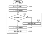
- the “air cleaning operation mode” is an operation mode for cleaning indoor air.
- the dehumidifier 1 starts air cleaning operation in the following steps.
- control device 18 sends a start signal to the drive circuit 13A so that the louver 13 opens the air outlet 12, and starts operating the louver drive motor 13M. Then, the louver 13 is opened to a predetermined position (step S101).
- the control device 18 rotates the motor 21a to control the fan 21 to rotate at a preset strong rotation speed (step S102).
- the control device 18 issues measurement commands to the dust sensor 62 and gas sensor 63.
- the dust sensor 62 and the gas sensor 63 each start detecting dust and gas in the air around the sensor and send the detection to the control device 18 .
- the control device 18 determines the level of air pollution from the acquired data (step 103).
- Information indicating the cleanliness of the air acquired by the dust sensor 62 and the gas sensor 63 is an example of environmental information according to the present disclosure.
- step S103 If it is determined in step S103 that the degree of air contamination is small, the control device 18 rotates the fan 21, which is currently being operated at a preset high speed, at a preset low speed. A command to change the rotational speed is issued to the drive circuit 28 (step S104). As a result, air cleaning operation (weak) is performed (step S105), and after a certain period of time, the process returns to step S103.
- step S103 determines whether the air is highly contaminated. If it is determined in step S103 that the air is highly contaminated, the control device 18 performs an air cleaning operation (strong) in which the fan 21 continues to operate at strong rotation (step S106). That is, in this case, the process returns to step S103 after a certain period of time without issuing a command to change the rotation speed to the drive circuit 28.
- strong air cleaning operation
- the operation notification unit 15 may notify that the filter is not placed in step S101. At this time, since the air cannot be purified because no filter is installed, the operation may be stopped. This eliminates wasteful operation and enables efficient operation.
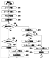
- the dehumidifying air cleaning operation mode automatically switches the operation mode of the dehumidifier 1 to a dehumidifying operation mode, an air cleaning operation mode, or the like, depending on the indoor humidity and air pollution state. For example, when the user turns on the main power switch of the input operation section 17 and selects the dehumidifying air cleaning operation mode with the operation mode changeover switch 17S, the dehumidifier 1 starts the dehumidifying air cleaning operation as follows.
- control device 18 issues a drive command to the drive circuit 28 and controls the louver drive motor 13M so that the louver 13 opens the air outlet 12 (step S201).
- control device 18 issues a drive command to the drive circuit 29 to open the shutter 51s, and controls the shutter motor 51m for opening and closing the shutter 51s. As a result, the entrance of the bypass air passage 43 is opened (step S202).
- control device 18 determines that the shutter 51s has been opened to a predetermined position, it issues a predetermined drive command to the drive circuit 28 in order to rotationally drive the motor 21a.
- the drive circuit 28 controls the rotation speed of the motor 21a so that the fan 21 rotates at a preset high rotation speed (step S203). Further, the control device 18 starts operating the compressor (step S204).
- the humidity sensor 61 starts a humidity detection operation and sends humidity detection data to the control device 18.
- the control device 18 determines whether the humidity is 50% or more (step S205).
- step S206 If the humidity is 50% or higher, continue driving the compressor.
- the dust sensor 62 and the gas sensor 63 start detecting dust and gas in the air around each sensor, and determine the degree of air pollution (step S206). If the degree of air contamination is small, the operations of steps S202, S203, and S204 are continued, and dehumidification operation is performed (step S207). Then, after a certain period of time has passed since step S206, the process returns to step S205.
- control device 18 controls the shutter motor 51m to close the shutter 51s, closes the entrance of the bypass air passage 43 (step S208), and performs a dehumidifying air purification operation (step S209). , after a certain period of time has elapsed from step S206, the process returns to step S205.
- step S205 if the humidity is lower than 50%, the control device 18 controls the compressor to stop driving (step S210).
- control device 18 controls the dust sensor 62 and the gas sensor 63 to start their detection operations, and determines the amount of dirt in the air (step S211).
- step S212 If the degree of air pollution is small, the motor 21a is controlled so that the fan 21 rotates at a preset low rotational speed (step S212), and a circulating operation is performed in which only air is blown without dehumidification (step S213). ), and after a certain period of time, the process returns to step S205.
- the control device 18 issues a closing command signal to the drive circuit 29 to close the shutter 51s.
- the drive circuit 29 starts operating the shutter motor 51m, moves the shutter 51s to the closed position, and the entrance of the bypass air passage 43 is closed (step S214).
- the fan 21 maintains the "strong operation” in step S203 and performs air purifying operation (step S215).
- the process returns to step S005 in the dehumidifying operation mode in FIG.
- the humidity threshold of the humidity sensor 61 in step S205 is set to 50%, but the threshold may be any other value.
- step S203 the fan 21 may be controlled to rotate at a preset medium rotation speed instead of a preset high rotation speed. Further, even if it is detected that the air is highly contaminated in steps S206 and S214, the shutter 51s may not close in steps S208 and S214. At this time, the operation may be stopped because the air cannot be purified. Further, in steps S202, S206, and S214, the flap may not be opened. That is, when the filter detection unit 64 detects that no filter is installed, the shutter 51s may not be controlled to open or close.
- the airflow restricting means 51 for opening and closing the entrance of the bypass air passage 43 is provided, it is possible to select which of the bypass air passage 43 and the main air passage 44 is suitable as an air passage for performing dehumidification operation and air purification operation.
- the dehumidifier 1 can be easily selected and can be easily used and operated efficiently.
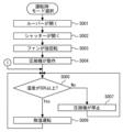
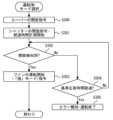
- FIG. 14 is a flowchart showing the basic operation steps of the control device 18 when the dehumidifier 1 of the first embodiment starts operating.
- the user turns on the main power switch using the input operation section 17 and operates the operation mode changeover switch 17S. In this way, an operation mode such as "dehumidification operation” or “air purification operation” is selected.
- control device 18 first checks whether there is any abnormality in its own internal configuration. If there is no abnormality in the initial abnormality determination, a command signal to open the louver 13 is issued to the drive circuit 13A (step S300).
- step S300 the louver 13 is quickly rotated to a predetermined open position by the louver drive motor 13M. Further, the control device 18 issues a command signal to the drive circuit 29 to open the shutter 51s. Then, the timer section 24T starts measuring the elapsed time from this point (step S301).
- the drive circuit 29 starts driving the shutter motor 51m of the airflow restricting means 51.
- the shutter 51s is rotated by a shutter motor 51m to an open position by a range of about 90 degrees about the upper rotation shaft 51a and the lower rotation shaft 51b. As a result, the entrance of the bypass air passage 43 is opened.
- control device 18 waits for the arrival of an open detection signal from the open/close detector 53 and determines whether the entrance of the bypass air passage 43 is opened (step S302). If the determination result in step S302 is "Yes”, a command signal to start blowing air is issued to the drive circuit 28.
- the command regarding the blowing intensity in this case is “strong”, and the fan 21 starts operating in the "strong” operation mode determined by the rated blowing capacity (step S303).
- step S304 if the elapsed time from step S301 does not exceed a predetermined "reference response time", for example, 10 seconds, the process returns to step S302 and the open detection signal from the open/close detector 53 is detected. Determine whether or not it is open or closed based on
- step S304 if the elapsed time from step S301 exceeds the "standard response time", it is determined that an abnormality has occurred in the airflow restricting means 51 for some reason, and the shutter 51s is opened by the notification unit 23. It is notified that it will not be done (step S305).
- the display unit 23D provides notification in text or graphics.
- the audio notification unit 23V may provide a notification such as "the bypass air path does not open properly” or the like. Then, after a certain period of time has elapsed from the time of these notifications, for example, 30 seconds, the main power switch is automatically turned off and the operation is automatically terminated.
- step S305 if the notification unit 23 notifies you to only perform an operation that does not use the bypass air path 43, and no input is made from the input operation unit 17 after that, the process will proceed as in step S305.
- the power may be automatically shut off.
- a shutter 51s is installed in each of the plurality of bypass air passages 43. If a shutter 51s that does not open or close in response to an instruction from the control device 18 is included among the plurality of shutters 51s, an abnormality of the shutter 51s is notified, that is, which shutter 51s has an abnormality. It may be configured as follows.
- the airflow restricting means 51 is configured to open and close the shutter 51s in response to an electric signal. Therefore, there is no need for the user to manually open and close the shutter 51s, and the burden on the user associated with the dehumidifying operation can be reduced.
- the attachment/detachment status of the filter can be detected, the operating status of the fan 21 can be appropriately controlled depending on whether the filter is installed or not, and efficient operation is possible. Furthermore, since it is possible to notify whether a filter is installed or not, it is possible to prevent forgetting to attach a filter. Furthermore, during the air cleaning operation and the dehumidifying air cleaning operation, it is also possible to notify that the air cannot be cleaned if a filter is not placed.
- the shutter motor 51m is arranged inside the upper wall of the bypass air passage 43, and the opening/closing detection sensor 53s is arranged inside the lower wall, making the structure of the dehumidifier 1 compact and simple. can. Further, the shutter 51s can be opened and closed reliably.
- the dehumidifier according to the present disclosure can be used, for example, to dehumidify indoor air.
Landscapes
- Engineering & Computer Science (AREA)
- Chemical & Material Sciences (AREA)
- Combustion & Propulsion (AREA)
- Mechanical Engineering (AREA)
- General Engineering & Computer Science (AREA)
- Drying Of Gases (AREA)
Abstract
A dehumidifier (1) comprising: a first air passage which is formed inside a housing, and in which an airflow from an intake port to an outlet port (12) passes through an air purification means to reach a dehumidification means; a second air passage which is formed inside the housing, and in which the airflow reaches the dehumidification means without passing through the air purification means; an airflow restriction means for restricting the flow of the airflow flowing through the second air passage; a compressor which supplies a refrigerant to the dehumidification means; a control device for controlling the airflow restriction means, the compressor, and a blowing means that generates the airflow; and an attachment/detachment detection means which detects the attachment/detachment state of the air purification means. The control device controls the blowing means in accordance with the detection result from the attachment/detachment detection means.
Description
本開示は、除湿機に関するものである。
The present disclosure relates to a dehumidifier.
特許文献1に除湿機が記載されている。特許文献1に示された除湿機は、吸気口から吸気される空気を熱交換器に通して除湿する。吸気口と熱交換器との通風路間で、熱交換器の前面側、つまり熱交換器から見て空気流の上流側の一部分を覆わないようにフィルターを配置している。フィルターが熱交換器の前面側を覆わない部分には、空気流を遮断できるシャッターを設けている。シャッターは、熱交換器への通路の一部を覆う位置と当該通路を覆わない位置とに選択可能に設けられている。
A dehumidifier is described in Patent Document 1. The dehumidifier shown in Patent Document 1 dehumidifies air taken in from an intake port by passing it through a heat exchanger. The filter is arranged between the air intake port and the heat exchanger so as not to cover the front side of the heat exchanger, that is, a portion of the upstream side of the airflow when viewed from the heat exchanger. In the area where the filter does not cover the front side of the heat exchanger, a shutter is provided to block air flow. The shutter is selectively provided in a position where it covers a portion of the passage to the heat exchanger and a position where it does not cover the passage.
特許文献1に開示の構成では、シャッターを開けた状態において、フィルターを通過しない空気が熱交換器の一部分のみを通過することで、空気流の速度分布が悪化し、除湿の効率が悪くなるという課題がある。
In the configuration disclosed in Patent Document 1, when the shutter is open, air that does not pass through the filter passes through only a portion of the heat exchanger, which deteriorates the velocity distribution of the airflow and deteriorates the dehumidification efficiency. There are challenges.
本開示は、上記のような課題を解決するためのものである。本開示の目的は、効率のよい運転が可能な除湿機を提供することである。
The present disclosure is intended to solve the above problems. An object of the present disclosure is to provide a dehumidifier that can be operated efficiently.
本開示に係る除湿機は、吸込口と吹出口とが形成された筐体と、前記吸込口から前記吹出口へ至る気流を発生させる送風手段と、前記筐体の内部に配置され、着脱自在に設けられた空気清浄化手段と、前記筐体の内部に配置され、前記気流の中の水分を除去する除湿手段と、を備える除湿機である。この除湿機は、前記筐体の内部に形成され、前記気流が前記空気清浄化手段を通過して前記除湿手段に至る第一の風路と、前記筐体の内部に形成され、前記気流が前記空気清浄化手段を通過せずに前記除湿手段に至る第二の風路と、前記第二の風路を流れる気流を制限する気流制限手段と、前記除湿手段に冷媒を供給する圧縮機と、前記送風手段、前記気流制限手段および前記圧縮機を制御する制御装置と、前記空気清浄化手段の着脱の状態を検知する着脱検知手段と、を有する。前記制御装置は、前記着脱検知手段の検知結果に応じて、前記送風手段を制御する。
The dehumidifier according to the present disclosure includes a casing in which an inlet and an outlet are formed, a blowing means for generating an airflow from the inlet to the outlet, and a dehumidifier that is disposed inside the casing and is detachable. The dehumidifier includes an air purifying means provided in the casing, and a dehumidifying means disposed inside the casing to remove moisture from the airflow. This dehumidifier includes a first air path formed inside the housing, through which the airflow passes through the air purifying means, and reaches the dehumidification means; a second air path leading to the dehumidifying means without passing through the air purifying means; an air flow restricting means for restricting airflow flowing through the second air path; and a compressor for supplying refrigerant to the dehumidifying means. , a control device for controlling the air blowing means, the air flow restricting means, and the compressor, and an attachment/detachment detection means for detecting the attachment/detachment state of the air purifying means. The control device controls the air blower according to the detection result of the attachment/detachment detection means.
また、本開示に係る除湿機は、吸込口と吹出口とが形成された筐体と、前記吸込口から前記吹出口へ至る気流を発生させる送風手段と、前記筐体の内部に配置され、着脱自在に設けられた空気清浄化手段と、前記筐体の内部に配置され、前記気流の中の水分を除去する除湿手段と、を備える除湿機である。この除湿機は、前記筐体の内部に形成され、前記気流が前記空気清浄化手段を通過して前記除湿手段に至る第一の風路と、前記筐体の内部に形成され、前記気流が前記空気清浄化手段を通過せずに前記除湿手段に至る第二の風路と、前記第二の風路における気流を通過させる状態と前記第二の風路における気流を遮断する状態とを選択できる開閉手段と、前記除湿手段に冷媒を供給する圧縮機と、前記送風手段、前記開閉手段及び前記圧縮機を制御する制御装置と、を有する。前記開閉手段は、前記第二の風路内に配置され、前記筐体の上下方向に2つの軸で軸支されている。前記2つの軸の一方側に位置制御機能付きモータを接続し、他方側に前記開閉手段が開放した状態か閉鎖した状態であるか検知する開閉検知手段を設けた。
Further, the dehumidifier according to the present disclosure includes a casing in which an inlet and an outlet are formed, a blower for generating an airflow from the inlet to the outlet, and disposed inside the casing, The dehumidifier includes an air purifying means that is detachably provided, and a dehumidifying means that is disposed inside the housing and removes moisture from the airflow. This dehumidifier includes a first air path formed inside the housing, through which the airflow passes through the air purifying means, and reaches the dehumidification means; Selecting a second air path that reaches the dehumidifying means without passing through the air purifying means, a state in which the air flow in the second air path is allowed to pass, and a state in which the air flow in the second air path is blocked. a compressor that supplies refrigerant to the dehumidifying means; and a control device that controls the blowing means, the opening and closing means, and the compressor. The opening/closing means is disposed within the second air path and is supported by two shafts in the vertical direction of the housing. A motor with a position control function is connected to one side of the two shafts, and an opening/closing detection means for detecting whether the opening/closing means is open or closed is provided on the other side.
本開示に係る除湿機によれば、効率のよい運転が可能である。
According to the dehumidifier according to the present disclosure, efficient operation is possible.
以下、添付の図面を参照して、実施の形態について説明する。各図における同一の符号は、同一の部分または相当する部分を示す。また、本開示では、重複する説明については適宜に簡略化または省略する。なお、本開示は、以下の実施の形態で説明する構成のうち、組み合わせ可能な構成のあらゆる組み合わせを含み得るものである。
Hereinafter, embodiments will be described with reference to the accompanying drawings. The same reference numerals in each figure indicate the same or corresponding parts. Further, in this disclosure, overlapping explanations will be simplified or omitted as appropriate. Note that the present disclosure may include all combinations of configurations that can be combined among the configurations described in the embodiments below.
実施の形態1.
図1は、実施の形態1の除湿機1を正面側から見た斜視図である。図2は、実施の形態1の除湿機1を背面側から見た斜視図である。図3は、図1に示したA-A線における垂直方向断面図である。図4は、図1に示したB-B線における水平方向断面図である。図5は、実施の形態1の除湿機の主要な制御構成を示すブロック図である。なお、本開示では、原則として、除湿機1が床面等の水平面に置かれた状態を基準にして、当該除湿機1について説明する。Embodiment 1.
FIG. 1 is a perspective view of adehumidifier 1 according to the first embodiment seen from the front side. FIG. 2 is a perspective view of the dehumidifier 1 according to the first embodiment, viewed from the back side. FIG. 3 is a vertical cross-sectional view taken along line AA shown in FIG. FIG. 4 is a horizontal cross-sectional view taken along line BB shown in FIG. FIG. 5 is a block diagram showing the main control configuration of the dehumidifier according to the first embodiment. In addition, in this disclosure, the dehumidifier 1 will be described based on the state in which the dehumidifier 1 is placed on a horizontal surface such as a floor surface.
図1は、実施の形態1の除湿機1を正面側から見た斜視図である。図2は、実施の形態1の除湿機1を背面側から見た斜視図である。図3は、図1に示したA-A線における垂直方向断面図である。図4は、図1に示したB-B線における水平方向断面図である。図5は、実施の形態1の除湿機の主要な制御構成を示すブロック図である。なお、本開示では、原則として、除湿機1が床面等の水平面に置かれた状態を基準にして、当該除湿機1について説明する。
FIG. 1 is a perspective view of a
図1から図4に示すように、除湿機1は、前ケース10Fと後ケース10Bとを備える。前ケース10Fと後ケース10Bとは、除湿機1の外殻を形成する筐体を構成する部材である。除湿機1の筐体は、複数個の車輪20が取り付けられた底板4を有している。前ケース10Fと後ケース10Bと底板4とによって、中空の箱型の筐体が構成されている。
As shown in FIGS. 1 to 4, the dehumidifier 1 includes a front case 10F and a rear case 10B. The front case 10F and the rear case 10B are members that constitute a casing that forms the outer shell of the dehumidifier 1. The housing of the dehumidifier 1 has a bottom plate 4 to which a plurality of wheels 20 are attached. The front case 10F, the rear case 10B, and the bottom plate 4 constitute a hollow box-shaped casing.
上記のように、底板4には、除湿機1を移動させるための複数個の車輪20が取り付けられている。複数個の車輪20は、前後左右に、互いに離れた位置に1つずつ、すなわち合計4つ配置されている。底板4には、圧縮機等の重量物が載置される。なお、本開示においては、図面の記載の明確化および簡略化のため、圧縮機については図示を省略している。
As mentioned above, a plurality of wheels 20 for moving the dehumidifier 1 are attached to the bottom plate 4. The plurality of wheels 20 are arranged one each at positions apart from each other in the front, back, left and right, that is, a total of four wheels 20 are arranged. A heavy object such as a compressor is placed on the bottom plate 4. Note that in the present disclosure, illustration of the compressor is omitted for clarity and simplification of the description of the drawings.
前ケース10Fと後ケース10Bとは、例えばネジ等の結合具で結合されることで、1つの箱形形状に組み立てられる。前ケース10Fは、除湿機1の前面部分を形成する部材である。後ケース10Bは、除湿機1の背面部分を形成する部材である。
The front case 10F and the rear case 10B are assembled into one box shape by being connected with a coupling device such as a screw, for example. The front case 10F is a member that forms the front part of the dehumidifier 1. The rear case 10B is a member that forms the back part of the dehumidifier 1.
前ケース10Fおよび後ケース10Bの上端部には、平板上の上ケース10Uが連結されている。上ケース10Uの前方には、ルーバー13が設けられている。上ケース10Uとルーバー13とは、前後から向かい合う形で当接するように配置される。閉じた状態のルーバー13は、上ケース10Uと共に、1つの平らな面を構成している。この面は、除湿機1の筐体の天面となっている。
A flat upper case 10U is connected to the upper ends of the front case 10F and the rear case 10B. A louver 13 is provided at the front of the upper case 10U. The upper case 10U and the louver 13 are arranged so as to face each other and come into contact with each other from the front and rear. The louver 13 in the closed state forms one flat surface together with the upper case 10U. This surface is the top surface of the casing of the dehumidifier 1.
除湿機1の筐体には、吸込口11と吹出口12とが形成される。吸込口11は、除湿機1の外部から内部へ空気を取り込むための開口である。吹出口12は、除湿機1の内部から外部へ空気を送り出すための開口である。
A suction port 11 and an air outlet 12 are formed in the casing of the dehumidifier 1. The suction port 11 is an opening for taking air into the dehumidifier 1 from the outside. The air outlet 12 is an opening for sending air from the inside of the dehumidifier 1 to the outside.
本実施の形態において、吸込口11は、後ケース10Bの中央部分に、正方形の窓状の開口として形成されている。また、吹出口12は、除湿機1の天面部分に形成されている。吹出口12が形成される箇所には、ルーバー13が配置されている。ルーバー13が一定の角度まで上方向に開くことで、吹出口12が開放される。
In this embodiment, the suction port 11 is formed as a square window-shaped opening in the center of the rear case 10B. Further, the air outlet 12 is formed on the top surface of the dehumidifier 1. A louver 13 is arranged at a location where the air outlet 12 is formed. The air outlet 12 is opened by opening the louver 13 upward to a certain angle.
上述したように、一例として、吸込口11は、除湿機1を背面方向から見た場合に正方形となっている。この吸込口11の形状は、本例に限定されるものではなく、例えば、長方形であってもよいし、円形であってもよい。
As mentioned above, as an example, the suction port 11 has a square shape when the dehumidifier 1 is viewed from the back side. The shape of this suction port 11 is not limited to this example, and may be rectangular or circular, for example.
除湿機1は、吸込口11を覆う吸込口カバー11aを備える。吸込口カバー11aは、吸込口11を介して除湿機1の内部へ異物が侵入してしまうことを防止する部材である。吸込口カバー11aは、例えば、空気中に舞い上がった紙くずおよび繊維くず等の異物が、除湿機1の内部に侵入することを防止する。吸込口カバー11aは、例えば、後ケース10Bに対して、着脱自在に固定される。
The dehumidifier 1 includes a suction port cover 11a that covers the suction port 11. The suction port cover 11a is a member that prevents foreign matter from entering the inside of the dehumidifier 1 through the suction port 11. The suction port cover 11a prevents foreign matter, such as paper scraps and fiber scraps, which are thrown into the air, from entering the inside of the dehumidifier 1, for example. For example, the suction port cover 11a is detachably fixed to the rear case 10B.
吸込口カバー11aは、例えば、格子状に形成される。吸込口カバー11aは、例えば、鎧戸状に形成されていてもよい。一例として、吸込口カバー11aの表面全体には、異物の侵入を防止するための網が取り付けられてもよい。あるいは、吸込口カバー11aは、プラスチック材料による一体成型によって網形状の部材として形成されてもよい。
The suction port cover 11a is formed, for example, in a grid shape. The suction port cover 11a may be formed into a shutter shape, for example. As an example, a net may be attached to the entire surface of the suction port cover 11a to prevent foreign matter from entering. Alternatively, the suction port cover 11a may be formed as a net-shaped member by integral molding of a plastic material.
上述したように、除湿機1は、図示しない圧縮機を備える。圧縮機の形式は、例えば、レシプロ式あるいはロータリー式等の何れの形式であっても良い。圧縮機は、モータを有しており、蒸発器31、第一凝縮器32aおよび第二凝縮器32bに繋がっている冷媒配管22の中に、冷媒を循環させる。圧縮機は、蒸発器31、第一凝縮器32a、第二凝縮器32bおよび図示しない減圧装置と共に、冷媒配管22で接続されて、冷凍サイクルを利用した冷媒回路を構成している。圧縮機は、冷媒回路に冷媒を圧縮して供給するものである。蒸発器31、第一凝縮器32a、第二凝縮器32bは、冷媒と空気との間での熱交換を行うための熱交換器である。減圧装置は、冷媒を減圧させる装置である。減圧装置は、例えば、膨張弁またはキャピラリーチューブである。
As mentioned above, the dehumidifier 1 includes a compressor (not shown). The compressor may be of any type, such as a reciprocating type or a rotary type. The compressor has a motor and circulates refrigerant through the refrigerant pipe 22 connected to the evaporator 31, the first condenser 32a, and the second condenser 32b. The compressor is connected to an evaporator 31, a first condenser 32a, a second condenser 32b, and a pressure reducing device (not shown) through a refrigerant pipe 22 to form a refrigerant circuit using a refrigeration cycle. The compressor compresses and supplies refrigerant to the refrigerant circuit. The evaporator 31, the first condenser 32a, and the second condenser 32b are heat exchangers for exchanging heat between the refrigerant and air. A pressure reducing device is a device that reduces the pressure of a refrigerant. The pressure reducing device is, for example, an expansion valve or a capillary tube.
図1に示すように、除湿機1は、貯水タンク7を備えている。貯水タンク7には、除湿動作に伴って蒸発器31の外部表面に発生するドレン水が滴下して導かれる。一例として、貯水タンク7は、前ケース10Fに形成された取出口から取り出すことができる。
As shown in FIG. 1, the dehumidifier 1 includes a water storage tank 7. Drain water generated on the external surface of the evaporator 31 during the dehumidifying operation is dripped and guided to the water storage tank 7 . As an example, the water storage tank 7 can be taken out from an outlet formed in the front case 10F.
ルーバー13は、一枚の板状の部材、あるいは、複数枚の板状の部材によって構成される。ルーバー13は、吹出口12から空気が送り出される方向を調整するためのものであり、開閉自在に設置されている。
The louver 13 is composed of a single plate-shaped member or a plurality of plate-shaped members. The louver 13 is for adjusting the direction in which air is sent out from the air outlet 12, and is installed so as to be openable and closable.
ルーバー13には、図5に示すルーバー駆動用モータ13Mが連結されている。ルーバー13は、このルーバー駆動用モータ13Mによって姿勢が変更される。ルーバー駆動用モータ13Mによって、ルーバー13は、吹出口12に対する傾斜角度を数段階に変化できる。これにより、吹出口12から吹き出される空気の方向を調整することができる。
A louver driving motor 13M shown in FIG. 5 is connected to the louver 13. The posture of the louver 13 is changed by this louver drive motor 13M. The louver drive motor 13M allows the louver 13 to change its inclination angle with respect to the air outlet 12 in several stages. Thereby, the direction of air blown out from the air outlet 12 can be adjusted.
ルーバー駆動用モータ13Mの運転は、図示を省略する制御基板に実装された駆動回路13Aからの駆動信号によって制御される。当該制御基板は、金属製あるいは不燃性の耐熱プラスチック製のケースとして形成された基板ボックス16の中に収容されている。
The operation of the louver drive motor 13M is controlled by a drive signal from a drive circuit 13A mounted on a control board (not shown). The control board is housed in a board box 16 formed as a case made of metal or nonflammable heat-resistant plastic.
基板ボックス16内には、1枚または複数枚の制御基板が収容される。この制御基板には、駆動回路13Aの他に、圧縮機を駆動するためのインバータ回路27と、後述するファン21を駆動するための駆動回路28と、がそれぞれ実装されている。
One or more control boards are housed in the board box 16. In addition to the drive circuit 13A, this control board includes an inverter circuit 27 for driving the compressor, and a drive circuit 28 for driving the fan 21, which will be described later.
除湿機1は、操作報知部15を備える。操作報知部15は、使用者が除湿機1を操作するための入力操作部17と各種の報知を行うための報知部23とから構成されている。報知部23は、例えば、除湿機1の状態等を文字等の可視情報で表示する。また、報知部23は、音声による報知も可能であってもよい。本実施の形態において、操作報知部15は、除湿機1の天面部に配置されている。上ケース10Uの内部には、操作報知部15に面するように、操作報知部15を制御する操作表示基板8が配置されている。
The dehumidifier 1 includes an operation notification section 15. The operation notification section 15 includes an input operation section 17 for the user to operate the dehumidifier 1, and a notification section 23 for making various notifications. The notification unit 23 displays, for example, the status of the dehumidifier 1 and the like using visible information such as characters. Further, the notification unit 23 may also be capable of providing audio notification. In this embodiment, the operation notification section 15 is arranged on the top of the dehumidifier 1. An operation display board 8 for controlling the operation notification section 15 is arranged inside the upper case 10U so as to face the operation notification section 15.
入力操作部17には、除湿機1の運転を開始および停止するための運転スイッチが配置されている。また、入力操作部17は、除湿機1の運転モードを、「除湿運転モード」、「空気清浄運転モード」および「除湿空気清浄運転モード」の3種類のいずれか1つに切り替えるための運転モード切換スイッチ17Sを有している。
An operation switch for starting and stopping the operation of the dehumidifier 1 is arranged in the input operation section 17. In addition, the input operation unit 17 is an operation mode for switching the operation mode of the dehumidifier 1 to any one of three types: "dehumidification operation mode", "air purification operation mode", and "dehumidification air purification operation mode". It has a changeover switch 17S.
除湿機1の内部には、ファン21が収容される。ファン21は、除湿機1の内部に空気を取り込み、取り込んだ空気を除湿機1の外部へ送る装置である。ファン21は、回転することで、吸込口11から吹出口12へ至る風路に、吸込口11から吹出口12へと向かう気流を発生させる。
A fan 21 is housed inside the dehumidifier 1. The fan 21 is a device that takes air into the dehumidifier 1 and sends the taken air to the outside of the dehumidifier 1. The fan 21 generates an airflow from the suction port 11 to the blowout port 12 in an air path from the suction port 11 to the blowout port 12 by rotating.
除湿機1の内部には、モータ21aが収容される。モータ21aは、ファン21を回転させる装置である。本実施の形態において、ファン21およびモータ21aは、除湿機1の正面側に配置される。モータ21aは、水平方向に伸びた回転軸21bを介し、ファン21の回転中心部に接続されている。ファン21およびモータ21aは、吸込口11から吹出口12へ至る気流を発生させる送風手段の一例を構成するものである。モータ21aの回転の開始、回転の停止および回転数は、駆動回路28によって制御される。
A motor 21a is housed inside the dehumidifier 1. The motor 21a is a device that rotates the fan 21. In this embodiment, fan 21 and motor 21a are arranged on the front side of dehumidifier 1. The motor 21a is connected to the rotation center of the fan 21 via a rotation shaft 21b extending in the horizontal direction. The fan 21 and the motor 21a constitute an example of a blowing means that generates an airflow from the suction port 11 to the blowout port 12. The start of rotation, the stop of rotation, and the rotation speed of the motor 21a are controlled by a drive circuit 28.
ファン21は、例えば、シロッコファンである。ファン21は、回転軸21bによって回転の中心部が固定されている。ファン21は、ファンケース36の内部に前方から空気を吸い込み、当該空気を吹出口12から吹き出させる。
The fan 21 is, for example, a sirocco fan. The center of rotation of the fan 21 is fixed by a rotating shaft 21b. The fan 21 sucks air into the fan case 36 from the front and blows the air out from the air outlet 12.
ファンケース36は、ファン21およびモータ21aの周囲を囲む。ファンケース36の前方側の壁面において、ファン21と対応した位置にベルマウス部37が形成されている。このベルマウス部37は、円形の大きな開口であり、口縁部が風下側に大きく湾曲している。ベルマウス部37は、第一凝縮器32aを通過した空気流を円滑に吸い込むように構成されている。
The fan case 36 surrounds the fan 21 and the motor 21a. A bell mouth portion 37 is formed on the front wall surface of the fan case 36 at a position corresponding to the fan 21. This bell mouth portion 37 is a large circular opening, and its mouth edge is largely curved toward the leeward side. The bell mouth portion 37 is configured to smoothly suck in the airflow that has passed through the first condenser 32a.
本実施の形態の除湿機1は、吸込口11から吹出口12に至る気流の中の水分を除去する除湿手段の一例として、蒸発器31、第一凝縮器32aおよび第二凝縮器32bを備える。蒸発器31、第一凝縮器32aおよび第二凝縮器32bは、除湿機1の筐体の内部に収容されている。蒸発器31、第一凝縮器32aおよび第二凝縮器32bは、図4に示すように、ベルマウス部37の前方側を塞ぐように、それぞれが垂直に設置されている。
The dehumidifier 1 of the present embodiment includes an evaporator 31, a first condenser 32a, and a second condenser 32b as an example of a dehumidifying means for removing moisture in the airflow from the suction port 11 to the blowout port 12. . The evaporator 31, the first condenser 32a, and the second condenser 32b are housed inside the casing of the dehumidifier 1. As shown in FIG. 4, the evaporator 31, the first condenser 32a, and the second condenser 32b are each installed vertically so as to close the front side of the bell mouth portion 37.
図6は、実施の形態1の除湿機1の吸込口カバー11aとHEPAフィルター41と活性炭フィルター42とを外した状態を背面側から見た斜視図である。除湿機1は、整流部材38を備える。整流部材38は、縦方向と横方向とに交わる枠状の部材から形成されており、それぞれ枠の間には、多数の通気窓が形成されている。つまり、この整流部材38は、格子状の部材を成している。
FIG. 6 is a perspective view of the dehumidifier 1 according to the first embodiment, with the suction port cover 11a, HEPA filter 41, and activated carbon filter 42 removed, as seen from the back side. The dehumidifier 1 includes a flow regulating member 38. The flow regulating member 38 is formed from a frame-shaped member that intersects in the vertical direction and the horizontal direction, and a large number of ventilation windows are formed between each frame. In other words, this rectifying member 38 forms a grid-like member.
整流部材38は、蒸発器31の後面と、第一の空間を隔てて対面している。つまり、整流部材38は、所定の距離をおいて蒸発器31と対向している。
The rectifying member 38 faces the rear surface of the evaporator 31 with a first space in between. That is, the rectifying member 38 faces the evaporator 31 at a predetermined distance.
また、この整流部材38は、活性炭フィルター42の前面との間に、第二の空間を隔てて対面している。つまり、整流部材38は、所定の距離をおいて活性炭フィルター42の前面と対向している。
Further, this rectifying member 38 faces the front surface of the activated carbon filter 42 with a second space in between. That is, the rectifying member 38 faces the front surface of the activated carbon filter 42 with a predetermined distance therebetween.
本実施の形態の除湿機1は、空気中の塵埃および臭気等を除去する空気清浄化手段の一例として、空気を清浄化するための空気清浄フィルターであるHEPAフィルター41と活性炭フィルター42とを備える。本実施の形態において、HEPAフィルター41および活性炭フィルター42は、後ケース10Bの内部に収納される。
The dehumidifier 1 of this embodiment includes a HEPA filter 41 and an activated carbon filter 42, which are air purifying filters for purifying the air, as an example of air purifying means for removing dust, odor, etc. from the air. . In this embodiment, HEPA filter 41 and activated carbon filter 42 are housed inside rear case 10B.
HEPAフィルター41は、空気中の細かい塵埃を捕集するフィルターである。HEPAフィルター41は、気流から塵埃を捕集する第一のフィルターの一例である。活性炭フィルター42は、空気を脱臭するフィルターである。活性炭フィルター42は、気流から臭気を除去する第二のフィルターの一例である。活性炭フィルター42は、前述したように、整流部材38の後面と、所定の距離の空間だけ離れて配置されている。
The HEPA filter 41 is a filter that collects fine dust in the air. HEPA filter 41 is an example of a first filter that collects dust from airflow. The activated carbon filter 42 is a filter that deodorizes the air. Activated carbon filter 42 is an example of a second filter that removes odors from the airflow. As described above, the activated carbon filter 42 is placed a predetermined distance apart from the rear surface of the flow regulating member 38.
HEPAフィルター41および活性炭フィルター42は、後ケース10Bより吸込口カバー11aを外した状態において、整流部材38の後方位置まで挿入できる。HEPAフィルター41および活性炭フィルター42は、後ケース10Bの内部に着脱自在に設置できる。
The HEPA filter 41 and activated carbon filter 42 can be inserted up to the rear position of the flow regulating member 38 with the suction port cover 11a removed from the rear case 10B. The HEPA filter 41 and the activated carbon filter 42 can be detachably installed inside the rear case 10B.
後ケース10Bには、空気清浄化手段であるフィルターの着脱の状態を検知する着脱件手段の一例として、フィルター検知部64が設けられている。一例として、フィルター検知部64は、HEPAフィルター41の縁部によって押下される検知レバー64aおよび検知スイッチから構成される。検知レバー64aは、HEPAフィルター41が設置されると押下され、検知レバー64aが押下されることにより、検知スイッチが押圧されてON状態となる。検知スイッチのON状態とOFF状態とは電気信号の有無により判別できる。
A filter detection section 64 is provided in the rear case 10B as an example of an attachment/detachment means for detecting the attachment/detachment state of a filter, which is an air purifying means. As an example, the filter detection unit 64 includes a detection lever 64a that is pressed down by the edge of the HEPA filter 41 and a detection switch. The detection lever 64a is pressed down when the HEPA filter 41 is installed, and when the detection lever 64a is pressed down, the detection switch is pressed and turned on. The ON state and OFF state of the detection switch can be determined by the presence or absence of an electric signal.
整流部材38は、HEPAフィルター41および活性炭フィルター42を後ケース10Bより取り外した状態において、使用者が蒸発器31に触れられないようにするための保護部材も兼ねている。例えば、前方から使用者が指等で整流部材38を押しても、その指等は蒸発器31に触れることはない。
The rectifying member 38 also serves as a protective member to prevent the user from touching the evaporator 31 when the HEPA filter 41 and activated carbon filter 42 are removed from the rear case 10B. For example, even if a user pushes the rectifying member 38 from the front with a finger or the like, the finger or the like will not touch the evaporator 31.
本実施の形態において、除湿機1の内部には、吸込口11から吹出口12へと通じる風路が形成されている。該風路の内部を流れる気流は、吸込口11から、吸込口カバー11a、HEPAフィルター41、活性炭フィルター42、蒸発器31、第二凝縮器32b、第一凝縮器32aおよびファン21を順に通過する。除湿機1の内部には、吸込口11から入った空気が、空気清浄化手段であるフィルターを通って各熱交換器からファン21の方に流れるための一連の風路が形成されている。
In this embodiment, an air path leading from the suction port 11 to the outlet 12 is formed inside the dehumidifier 1. The airflow flowing inside the air passage passes through the suction port 11, the suction port cover 11a, the HEPA filter 41, the activated carbon filter 42, the evaporator 31, the second condenser 32b, the first condenser 32a, and the fan 21 in this order. . Inside the dehumidifier 1, a series of air passages are formed through which air entering from the suction port 11 passes through a filter, which is an air purifying means, and flows from each heat exchanger toward the fan 21.
ここで、吸込口11から吹出口12へと通じる風路を流れる気流を用いて、上流側と下流側とを定める。例えば、蒸発器31等の熱交換器に対して吸込口11がある側を上流側とする。また、蒸発器31等の熱交換器に対して吹出口12がある側を下流側とする。
Here, the upstream side and the downstream side are defined using the airflow flowing through the air path leading from the inlet 11 to the outlet 12. For example, the side where the suction port 11 is located with respect to the heat exchanger such as the evaporator 31 is defined as the upstream side. Further, the side where the air outlet 12 is located with respect to the heat exchanger such as the evaporator 31 is defined as the downstream side.
図5に示すように、除湿機1は、塵埃センサー62を備える。この塵埃センサー62は、除湿機1の内部に配置される。塵埃センサー62の近傍には、塵埃センサー62が除湿機1の外側と連通するための小さな開口が設けられる。塵埃センサー62および制御装置18により、塵埃検出情報を取得することができる。塵埃センサー62および制御装置18により、除湿機1が設置された室内空間の塵埃の量と濃度とを測定することができる。塵埃センサー62は、例えば、0.1μmの粒子を検出する性能を持つ。塵埃センサー62の検知結果は制御装置18によって取得され、この取得した塵埃検出情報を操作報知部15に表示させることができる。
As shown in FIG. 5, the dehumidifier 1 includes a dust sensor 62. This dust sensor 62 is arranged inside the dehumidifier 1. A small opening is provided near the dust sensor 62 so that the dust sensor 62 communicates with the outside of the dehumidifier 1. Dust sensor 62 and control device 18 can acquire dust detection information. The dust sensor 62 and the control device 18 can measure the amount and concentration of dust in the indoor space where the dehumidifier 1 is installed. The dust sensor 62 has the ability to detect particles of 0.1 μm, for example. The detection result of the dust sensor 62 is acquired by the control device 18, and the acquired dust detection information can be displayed on the operation notification section 15.
図5に示すように、除湿機1は、ガスセンサー63を備える。このガスセンサー63は、除湿機1の内部に配置され、ガスセンサー63の近傍には、ガスセンサー63が除湿機1の外側と連通するため小さな開口が設けられる。ガスセンサー63と制御装置18とによりガス検出情報を取得し、室内の空気の臭気を測定することができる。ガスセンサー63の検知結果は制御装置18によって取得され、この取得したガス検出情報を操作報知部15に表示させることができる。
As shown in FIG. 5, the dehumidifier 1 includes a gas sensor 63. This gas sensor 63 is arranged inside the dehumidifier 1, and a small opening is provided near the gas sensor 63 so that the gas sensor 63 communicates with the outside of the dehumidifier 1. Gas detection information is acquired by the gas sensor 63 and the control device 18, and the odor of indoor air can be measured. The detection result of the gas sensor 63 is acquired by the control device 18, and the acquired gas detection information can be displayed on the operation notification section 15.
図5に示すように、除湿機1は、無線通信部26を備える。無線通信部26は、上ケース10Uの内部の天井部付近に収容される。無線通信部26は、除湿機1のある家庭内あるいは事務所に設置した無線ルーター等のローカルネットワーク設備との間で無線通信できるようになっている。無線通信部26は、ローカルネットワーク設備を介してインターネット回線に接続される場合もある。
As shown in FIG. 5, the dehumidifier 1 includes a wireless communication section 26. The wireless communication unit 26 is housed near the ceiling inside the upper case 10U. The wireless communication unit 26 is capable of wireless communication with local network equipment such as a wireless router installed in the home or office where the dehumidifier 1 is located. The wireless communication unit 26 may be connected to the Internet line via local network equipment.
例えば、無線通信部26は、インターネット回線を通じて、遠隔地にあるスマートフォン等の情報処理端末器およびその他の通信機器と情報の授受ができる。なお、ローカルネットワーク設備とは、家庭内あるいは事務所内部の総電力使用量を制御する指令装置、あるいは、複数の電気機器の情報を収集して連携させる統合管理装置等でも良く、また、「アクセスポイント」ともいう場合がある。
For example, the wireless communication unit 26 can exchange information with an information processing terminal such as a smartphone and other communication devices located at a remote location via an Internet line. Note that the local network equipment may be a command device that controls the total amount of electricity used in a home or office, or an integrated management device that collects and coordinates information on multiple electrical devices. Also called "point".
HEPAフィルター41および活性炭フィルター42の左右には、隣接してバイパス風路43がある。バイパス風路43は、後ケース10Bの内部において、吸込口11の高さ方向の全域に亘って設けられる空間である。
There are bypass air passages 43 adjacent to the left and right sides of the HEPA filter 41 and the activated carbon filter 42. The bypass air passage 43 is a space provided throughout the height direction of the suction port 11 inside the rear case 10B.
バイパス風路43は、吸込口11から前方に伸びている風路である。バイパス風路43は、後方から前方に伸びた、幅の狭い空間である。バイパス風路43は、バイパス風路外壁43aとフィルターケース外壁43bとに挟まれた風路である。バイパス風路外壁43aの後方端部とフィルターケース外壁43bの後方端部との間の空隙は、バイパス風路43の入口となっている。一方、バイパス風路外壁43aの前方端部は、整流部材38の外周端部に接触しており、バイパス風路43の途中で気流が外へ漏れないようになっている。バイパス風路外壁43aの前方端部とフィルターケース外壁43bの前方端部との間の空隙は、バイパス風路43の出口となっている。
The bypass air path 43 is an air path that extends forward from the suction port 11. The bypass air passage 43 is a narrow space extending from the rear to the front. The bypass air passage 43 is an air passage sandwiched between a bypass air passage outer wall 43a and a filter case outer wall 43b. The gap between the rear end of the bypass air passage outer wall 43a and the rear end of the filter case outer wall 43b serves as an entrance to the bypass air passage 43. On the other hand, the front end of the bypass air passage outer wall 43a is in contact with the outer peripheral end of the flow regulating member 38, so that airflow does not leak outside in the middle of the bypass air passage 43. A gap between the front end of the bypass air passage outer wall 43a and the front end of the filter case outer wall 43b serves as an outlet of the bypass air passage 43.
本実施の形態において、吸込口11から吹出口12へと通じる風路は、第一の風路であるメイン風路44と第二の風路であるバイパス風路43との2つの風路から構成されている。メイン風路44は、吸込口11からHEPAフィルター41と活性炭フィルター42とを通過して整流部材38に至る風路である。バイパス風路43は、吸込口11からHEPAフィルター41と活性炭フィルター42とを通過せずに、整流部材38に至る風路である。メイン風路44とバイパス風路43とは、整流部材38の直前で合流する。
In this embodiment, the air passage leading from the inlet 11 to the outlet 12 includes two air passages: a main air passage 44 that is a first air passage and a bypass air passage 43 that is a second air passage. It is configured. The main air passage 44 is an air passage that extends from the suction port 11 through the HEPA filter 41 and the activated carbon filter 42 and reaches the flow regulating member 38. The bypass air passage 43 is an air passage from the suction port 11 to the rectifying member 38 without passing through the HEPA filter 41 and the activated carbon filter 42 . The main air passage 44 and the bypass air passage 43 join immediately before the flow straightening member 38.
除湿機1は、バイパス風路43の入口を実質的に開閉して、バイパス風路43を流れる気流を制限するための気流制限手段51を備えている。この気流制限手段51は、吸込口11の左右にそれぞれ配置される。なお、気流制限手段51の構成としては、バイパス風路43を流れる気流を制限することができるものであれば、任意の構成を採用することができる。以下、本実施の形態では、気流制限手段51として、具体的な一例として、開閉手段であるシャッター51sを採用した構成について説明する。
The dehumidifier 1 includes an airflow restriction means 51 for substantially opening and closing the inlet of the bypass airway 43 to restrict the airflow flowing through the bypass airway 43. The airflow restricting means 51 are arranged on the left and right sides of the suction port 11, respectively. Note that as the configuration of the airflow restricting means 51, any configuration can be adopted as long as it is capable of restricting the airflow flowing through the bypass air path 43. Hereinafter, in this embodiment, as a specific example of the airflow restricting means 51, a configuration will be described in which a shutter 51s, which is an opening/closing means, is adopted.
図7は、実施の形態1における空気の流れを簡単に説明するための模式図である。バイパス風路43は、気流ABがHEPAフィルター41と活性炭フィルター42とを通過せずに下流へ流れる風路である。このバイパス風路43に対し、HEPAフィルター41と活性炭フィルター42とを気流AFが通過する風路が、メイン風路44である。
FIG. 7 is a schematic diagram for easily explaining the flow of air in the first embodiment. The bypass air passage 43 is an air passage through which the air flow AB flows downstream without passing through the HEPA filter 41 and the activated carbon filter 42. In contrast to the bypass air path 43, a main air path 44 is an air path through which the airflow AF passes through the HEPA filter 41 and the activated carbon filter 42.
バイパス風路43は、HEPAフィルター41と活性炭フィルター42とを挟んで、その右側と左側とに、それぞれ形成されている。バイパス風路43とメイン風路44とは、左右に隣接して並行に配置されている。
Bypass air passages 43 are formed on the right and left sides of the HEPA filter 41 and activated carbon filter 42, respectively. The bypass air passage 43 and the main air passage 44 are arranged adjacent to each other on the left and right in parallel.
バイパス風路43を通過する気流ABとメイン風路44を通過する気流AFとは、HEPAフィルター41および活性炭フィルター42の内部では合流しない。
The airflow AB passing through the bypass air passage 43 and the airflow AF passing through the main air passage 44 do not merge inside the HEPA filter 41 and the activated carbon filter 42.
空気清浄化手段であるフィルターを通過しない風路であるバイパス風路43と、フィルターを通過する風路であるメイン風路44とを隣接して配置することにより、除湿機1の中の風路をコンパクトに構成でき、除湿機1が小型化できる。なお、除湿機1を背面側から見た場合において、バイパス風路43の縦方向の高さ寸法は、HEPAフィルター41の縦方向の長さと同程度に設定するのが望ましい。
By arranging the bypass air path 43, which is an air path that does not pass through a filter serving as an air purifying means, and the main air path 44, which is an air path that passes through a filter, adjacent to each other, the air path inside the dehumidifier 1 is improved. can be configured compactly, and the dehumidifier 1 can be downsized. Note that when the dehumidifier 1 is viewed from the back side, it is desirable that the vertical height of the bypass air passage 43 is set to be approximately the same as the length of the HEPA filter 41 in the vertical direction.
バイパス風路43に流れるバイパス気流ABとメイン風路44に流れるメイン気流AFとは、活性炭フィルター42の下流の空間、つまり、整流部材38を起点として一定距離だけ離れた第一の空間と、整流部材38を起点として一定距離の間隔を有した第二の空間とにおいて合流する。バイパス気流ABとメイン気流AFは、活性炭フィルター42の下流に配置される蒸発器31の手前で合流し、その後は1つの風路の中を流れる。
The bypass airflow AB flowing in the bypass airflow path 43 and the main airflow AF flowing in the main airflow path 44 are connected to a space downstream of the activated carbon filter 42, that is, a first space a certain distance apart from the rectification member 38 as a starting point, and a rectification. Starting from the member 38, it merges with a second space spaced a certain distance apart. The bypass airflow AB and the main airflow AF merge before the evaporator 31 located downstream of the activated carbon filter 42, and thereafter flow in one air path.
図8は、実施の形態1のシャッター51sの構成を示す簡略図である。図9は、実施の形態1においてシャッター51sがバイパス風路43を遮蔽しているときの要部断面図である。図10は、実施の形態1においてシャッター51sがバイパス風路43を開放しているときの要部断面図である。本実施の形態において、シャッター51sは、バイパス風路43に設けられている。シャッター51sは、除湿機1の筐体の上下方向に2つの軸で軸支されている。シャッター51sは、上側回転軸51aと下側回転軸51bとを有する。バイパス風路43のバイパス上壁65とバイパス下壁66とには、それぞれ上側軸受け65aと下側軸受け66aとが設けられている。シャッター51sの上側回転軸51aと下側回転軸51bは、それぞれ、上側軸受け65aと下側軸受け66aとに挿入されており、シャッター51sは回転自在となっている。
FIG. 8 is a simplified diagram showing the configuration of the shutter 51s of the first embodiment. FIG. 9 is a sectional view of a main part when the shutter 51s is shielding the bypass air passage 43 in the first embodiment. FIG. 10 is a sectional view of a main part when the shutter 51s opens the bypass air passage 43 in the first embodiment. In this embodiment, the shutter 51s is provided in the bypass air passage 43. The shutter 51s is supported by two shafts in the vertical direction of the casing of the dehumidifier 1. The shutter 51s has an upper rotation shaft 51a and a lower rotation shaft 51b. The upper bypass wall 65 and lower bypass wall 66 of the bypass air passage 43 are provided with an upper bearing 65a and a lower bearing 66a, respectively. The upper rotation shaft 51a and the lower rotation shaft 51b of the shutter 51s are inserted into the upper bearing 65a and the lower bearing 66a, respectively, so that the shutter 51s is rotatable.
バイパス風路43のバイパス上壁65の内部には、シャッターモータ51mが配置される。シャッター51sの上側回転軸51aは、シャッターモータ51mの回転軸に接続される。シャッターモータ51mは、位置制御機能付きのモータである。シャッターモータ51mの回転位置を制御することで、シャッター51sは、図9に示すようにバイパス風路43の気流を遮断する位置と、図10に示すようにバイパス風路43の気流を通過させる位置と、の間で回転動作する。シャッター51sは、第二の風路であるバイパス風路43における気流を通過させる状態とバイパス風路43における気流を遮断する状態とを選択できる。
A shutter motor 51m is arranged inside the bypass upper wall 65 of the bypass air passage 43. The upper rotating shaft 51a of the shutter 51s is connected to the rotating shaft of the shutter motor 51m. The shutter motor 51m is a motor with a position control function. By controlling the rotational position of the shutter motor 51m, the shutter 51s can be moved to a position where the airflow in the bypass air path 43 is blocked, as shown in FIG. 9, and a position where the airflow is allowed to pass through the bypass air path 43, as shown in FIG. It rotates between . The shutter 51s can select between a state in which the airflow in the bypass air path 43, which is the second air path, is allowed to pass through and a state in which the airflow in the bypass air path 43 is blocked.
また、シャッター51sには、シャッター51sが開放した状態であるか閉鎖した状態であるか検知する開閉検知手段として、開閉検知部53が設けられている。開閉検知部53は、任意に構成し得るが、ここでは一例として、開閉検知センサー53sについて説明する。バイパス風路43のバイパス下壁66の内部に、開閉検知センサー53sを配置する。開閉検知センサー53sは、磁気を検知して信号のON/OFFを行うものであり、例えば、ホールICあるいはリードスイッチなどを用いることができる。
Further, the shutter 51s is provided with an opening/closing detection section 53 as an opening/closing detection means for detecting whether the shutter 51s is in an open state or a closed state. Although the opening/closing detection section 53 can be configured arbitrarily, the opening/closing detection sensor 53s will be described here as an example. An opening/closing detection sensor 53s is arranged inside the bypass lower wall 66 of the bypass air passage 43. The opening/closing detection sensor 53s detects magnetism to turn ON/OFF a signal, and can use, for example, a Hall IC or a reed switch.
シャッター51sの下端部壁面には、磁石53aを設置する。シャッター51sがバイパス風路43を開放する位置にいるときに開閉検知センサー53sに対向する位置に磁石53aを設置する。シャッター51sが、バイパス風路43を開放する位置となった時に、開閉検知センサー53sが磁石53aを検知することで、バイパス風路43の開放を判定することができる。
A magnet 53a is installed on the wall surface of the lower end of the shutter 51s. A magnet 53a is installed at a position facing the opening/closing detection sensor 53s when the shutter 51s is in a position to open the bypass air passage 43. When the shutter 51s is at the position where the bypass air passage 43 is opened, the opening/closing detection sensor 53s detects the magnet 53a, thereby making it possible to determine whether the bypass air passage 43 is open.
バイパス風路43のバイパス上壁65の内部にシャッターモータ51mを配置し、バイパス下壁66の内部に開閉検知センサー53sを配置したので、コンパクトかつ簡単な構となる。本実施の形態では、シャッターモータ51mと開閉検知センサー53sとを向かい合う位置に構成する。
The shutter motor 51m is arranged inside the bypass upper wall 65 of the bypass air passage 43, and the opening/closing detection sensor 53s is arranged inside the bypass lower wall 66, resulting in a compact and simple structure. In this embodiment, the shutter motor 51m and the opening/closing detection sensor 53s are configured to face each other.
次に、本実施の形態の除湿機1の運転について説明する。実施の形態1では、あらかじめ設定された、いくつかの「運転モード」が制御装置18の記憶手段25に記憶されている。
Next, the operation of the dehumidifier 1 of this embodiment will be explained. In the first embodiment, several preset "operation modes" are stored in the storage means 25 of the control device 18.
「運転モード」の一例として、「除湿運転モード」、「空気清浄運転モード」および「除湿空気清浄自動運転モード」がある。図11は、実施の形態1の除湿機1の除湿運転時の、動作ステップを示すフローチャートである。図12は、実施の形態1の除湿機1の空気清浄運転時の動作ステップを示すフローチャートである。図13は、実施の形態1の除湿機1の除湿空気清浄運転時の動作ステップを示すフローチャートである
Examples of "operating modes" include "dehumidifying operating mode," "air purifying operating mode," and "dehumidifying air purifying automatic operating mode." FIG. 11 is a flowchart showing operation steps during dehumidifying operation of the dehumidifier 1 of the first embodiment. FIG. 12 is a flowchart showing operational steps during air purifying operation of the dehumidifier 1 of the first embodiment. FIG. 13 is a flowchart showing operation steps during dehumidifying air cleaning operation of the dehumidifier 1 according to the first embodiment.
除湿機1の運転停止中は、制御装置18により、圧縮機の駆動用のインバータ回路27とルーバー13のルーバー駆動用モータ13Mとモータ21aとが、全て停止するよう制御されている。すなわち、圧縮機のモータ、ルーバー駆動用モータ13Mおよびモータ21aには電力が供給されていない。このとき、ルーバー13とシャッター51sとは、それぞれ、吹出口12とバイパス風路43の入口とを閉じた状態で維持されている。
While the operation of the dehumidifier 1 is stopped, the control device 18 controls the inverter circuit 27 for driving the compressor, the louver driving motor 13M of the louver 13, and the motor 21a to all stop. That is, power is not supplied to the compressor motor, the louver drive motor 13M, and the motor 21a. At this time, the louver 13 and the shutter 51s are maintained in a state where the air outlet 12 and the entrance of the bypass air passage 43 are closed, respectively.
図11を用いて、「除湿運転モード」を開始した場合について説明する。「除湿運転モード」は、室内を除湿するための運転モードである。例えば、使用者が入力操作部17の運転スイッチをONにして制御装置18を起動させることで、除湿機1の運転を開始することができる。
The case where the "dehumidification operation mode" is started will be explained using FIG. 11. "Dehumidification operation mode" is an operation mode for dehumidifying the room. For example, the user can start the operation of the dehumidifier 1 by turning on the operation switch of the input operation section 17 and activating the control device 18.
運転モード切換スイッチ17Sで除湿運転モードが選択されると、除湿機1は、以下に示すようなステップによって、除湿運転を開始する。
When the dehumidifying operation mode is selected with the operation mode changeover switch 17S, the dehumidifier 1 starts dehumidifying operation through the steps shown below.
最初に、制御装置18は、ルーバー13が吹出口12を開くように、ルーバー駆動用モータ13Mへの通電を開始させ、ルーバー13の位置を制御する(ステップS001)。
First, the control device 18 starts energizing the louver drive motor 13M and controls the position of the louver 13 so that the louver 13 opens the air outlet 12 (step S001).
ルーバー駆動用モータ13Mには、例えば、ステッピングモータが使用される。ルーバー駆動用モータ13Mは、駆動回路13Aからの駆動信号に対応して一定角度ずつ所定の方向に回動する。ルーバー駆動用モータ13Mの内部の機械的な構造により、高精度な位置決めをオープンループ制御でも可能にしている。駆動回路13Aからのパルス数に応じて、ルーバー駆動用モータ13Mはステップ角度で動く。これによって、ルーバー13を指定の角度、例えば、45度、60度あるいは75度等、まで開いた状態に維持できる。
For example, a stepping motor is used as the louver drive motor 13M. The louver drive motor 13M rotates in a predetermined direction by a constant angle in response to a drive signal from the drive circuit 13A. The internal mechanical structure of the louver drive motor 13M enables highly accurate positioning even under open loop control. The louver drive motor 13M moves at a step angle in accordance with the number of pulses from the drive circuit 13A. This allows the louver 13 to be maintained open to a specified angle, such as 45 degrees, 60 degrees, or 75 degrees.
次に、制御装置18は、シャッター51sが開放位置まで開くように駆動回路29に指令信号を発することで、シャッターモータ51mに駆動電力を与えてシャッター51sの位置を制御する。
Next, the control device 18 controls the position of the shutter 51s by issuing a command signal to the drive circuit 29 so that the shutter 51s opens to the open position, thereby applying drive power to the shutter motor 51m.
シャッターモータ51mには、例えば、ステッピングモータが使用される。駆動回路29からの駆動信号に対応して、シャッター51sは一定角度ずつ所定の方向に回動する。この回動動作によって、バイパス風路43の入口が開かれる(ステップS002)。
For example, a stepping motor is used as the shutter motor 51m. In response to a drive signal from the drive circuit 29, the shutter 51s rotates in a predetermined direction by a constant angle. This rotational movement opens the entrance of the bypass air passage 43 (step S002).
バイパス風路43を閉鎖する場合には、シャッター51sは図9に示すような閉鎖位置となる。このとき、開閉検知センサー53sに対向する位置に磁石53aがない状態なので、開閉検知センサー53sはOFFの状態となる。開閉検知センサー53sは、OFFの状態となっている信号を発する。
When closing the bypass air passage 43, the shutter 51s is in the closed position as shown in FIG. 9. At this time, since the magnet 53a is not located at a position facing the opening/closing detection sensor 53s, the opening/closing detection sensor 53s is in an OFF state. The opening/closing detection sensor 53s emits a signal indicating an OFF state.
バイパス風路43を開放する場合には、シャッター51sは、図10に示すような開放位置となる。このとき、開閉検知センサー53sの対抗の位置に磁石53aがある状態なので、開閉検知センサー53sはONの状態となる。開閉検知センサー53sは、ONの状態となっている信号を発する。これによって、シャッター51sが確実にバイパス風路43を開放したことを、制御装置18は判定できる。
When opening the bypass air passage 43, the shutter 51s is in the open position as shown in FIG. 10. At this time, since the magnet 53a is in a position opposite to the opening/closing detection sensor 53s, the opening/closing detection sensor 53s is in an ON state. The opening/closing detection sensor 53s emits a signal that is in an ON state. Thereby, the control device 18 can determine that the shutter 51s has reliably opened the bypass air passage 43.
上述したように、シャッターモータ51mにステッピングモータが使用されているので、駆動回路29からの駆動信号に対応して、一定角度ずつ所定の方向にシャッター51sは回動する。このため、開閉検知部53を省略しても良い。
As described above, since a stepping motor is used as the shutter motor 51m, the shutter 51s rotates in a predetermined direction by a constant angle in response to a drive signal from the drive circuit 29. Therefore, the opening/closing detection section 53 may be omitted.
本実施の形態では、除湿機1の基本的な機能に関係しているシャッター51sの開閉動作を重視し、この開閉に何らかの不備があった場合にも異常なく運転を行えるように、開閉検知部53を設けている。
In this embodiment, emphasis is placed on the opening/closing operation of the shutter 51s, which is related to the basic functions of the dehumidifier 1, and the opening/closing detection unit is designed so that the operation can be performed without any abnormality even if there is some kind of defect in this opening/closing. 53 are provided.
制御装置18は、シャッター51sが開放した状態であることをステップS002で判定した後、モータ21aを駆動して、ファン21があらかじめ設定された強回転の回転数で回転するように制御する(ステップS003)。また、圧縮機が駆動するようにインバータ回路27を制御する。(ステップS004)。
After determining in step S002 that the shutter 51s is in an open state, the control device 18 drives the motor 21a to control the fan 21 to rotate at a preset strong rotation speed (step S002). S003). It also controls the inverter circuit 27 to drive the compressor. (Step S004).
制御装置18は、例えば、湿度センサー61を利用して湿度を把握する。湿度センサー61は、周囲の空気の湿度検知動作を開始し、制御装置18に検知データを送信する。これにより、制御装置18において、湿度が閾値、例えば50%以上であるかを判定する(ステップS005)。湿度の情報は、本開示に係る環境情報の一例である。湿度50%以上の場合は、圧縮機の駆動動作を継続して除湿運転を行い(S006)、一定時間後、ステップS005に戻る。
The control device 18 uses, for example, the humidity sensor 61 to grasp the humidity. The humidity sensor 61 starts an operation of detecting the humidity of the surrounding air and transmits detection data to the control device 18. Thereby, the control device 18 determines whether the humidity is equal to or higher than a threshold value, for example, 50% (step S005). Humidity information is an example of environmental information according to the present disclosure. If the humidity is 50% or more, the compressor continues to be driven to perform dehumidifying operation (S006), and after a certain period of time, returns to step S005.
一方、ステップS005の判定で湿度が50%より低い場合は、制御装置18は圧縮機を停止するよう制御し、圧縮機による冷媒圧縮動作が停止する(ステップS007)。このとき、制御装置18は、ファン21のモータ21aの回転駆動動作を継続するよう制御し、一定時間後、ステップS005に戻る。なお、以上の説明では、除湿運転モードの運転可否の判定基準の一例として、湿度センサー61の湿度検知の閾値を50%としたが、閾値はこれ以外の値でもよい。
On the other hand, if the humidity is lower than 50% as determined in step S005, the control device 18 controls the compressor to stop, and the refrigerant compression operation by the compressor is stopped (step S007). At this time, the control device 18 controls the motor 21a of the fan 21 to continue its rotational driving operation, and returns to step S005 after a certain period of time. In the above description, as an example of the criterion for determining whether or not the dehumidifying operation mode can be operated, the humidity detection threshold of the humidity sensor 61 is set to 50%, but the threshold may be any other value.
フィルター検知部64においてフィルターが設置されていないことを検知した場合は、ステップS003において、ファン21があらかじめ設定された強回転の回転数ではなく、あらかじめ設定された中回転の回転数で回転するように制御してもよい。フィルターが設置されていない場合は、フィルターが配置されている場合と比較して同じ回転数では、風量が大きくなりすぎてしまうためである。このように、フィルター検知部64の検知結果に応じてファン21が制御されることで、効率のよい除湿が可能である。なお、フィルター検知部64は、2つのフィルターの両方の設置有無を検知可能に構成されていてもよいし、どちらか一方を検知するように構成されてもよい。また、フィルターが配置されていないことを、操作報知部15によって報知しても良い。ただし、このとき、フィルターは配置されていなくても、除湿はできるので運転は継続してもよい。また、このとき、ステップS002において、シャッター51sを開かないように制御しても良い。すなわち、フィルター検知部64においてフィルターが設置されていないことを検知した場合は、シャッター51sの開閉制御を行わなくてもよい。
If the filter detection unit 64 detects that no filter is installed, in step S003, the fan 21 is configured to rotate at a preset medium rotation speed instead of a preset high rotation speed. may be controlled. This is because when a filter is not installed, the air volume becomes too large at the same rotation speed as compared to when a filter is installed. In this way, by controlling the fan 21 according to the detection result of the filter detection unit 64, efficient dehumidification is possible. Note that the filter detection unit 64 may be configured to be able to detect whether or not both of the two filters are installed, or may be configured to detect either one of them. Furthermore, the operation notification unit 15 may notify that the filter is not placed. However, at this time, even if the filter is not installed, dehumidification can be performed, so operation may continue. Further, at this time, in step S002, the shutter 51s may be controlled not to open. That is, when the filter detection unit 64 detects that no filter is installed, it is not necessary to control the opening and closing of the shutter 51s.
次に、図12を用いて、「空気清浄運転モード」の場合について説明する。「空気清浄運転モード」は、室内空気を清浄化するための運転モードである。例えば、使用者が入力操作部17の主電源スイッチをONにし、運転モード切換スイッチ17Sで空気清浄運転モードを選択すると、除湿機1は、以下のようなステップで、空気清浄運転を開始する。
Next, the case of "air cleaning operation mode" will be explained using FIG. 12. The "air cleaning operation mode" is an operation mode for cleaning indoor air. For example, when the user turns on the main power switch of the input operation unit 17 and selects the air cleaning operation mode with the operation mode changeover switch 17S, the dehumidifier 1 starts air cleaning operation in the following steps.
最初に、制御装置18は、ルーバー13が吹出口12を開くように駆動回路13Aに起動信号を送信して、ルーバー駆動用モータ13Mの運転を開始する。すると、ルーバー13は、所定の位置まで開放される(ステップS101)。
First, the control device 18 sends a start signal to the drive circuit 13A so that the louver 13 opens the air outlet 12, and starts operating the louver drive motor 13M. Then, the louver 13 is opened to a predetermined position (step S101).
次に、制御装置18は、モータ21aを回転駆動して、ファン21があらかじめ設定された強回転の回転数で回転するように制御する(ステップS102)。制御装置18は、塵埃センサー62とガスセンサー63とに、計測指令を発する。塵埃センサー62とガスセンサー63とは、それぞれセンサーの周囲の空気の塵埃とガスの検知動作を開始し、制御装置18に送信する。制御装置18は、取得したデータから、空気の汚れの大小を判定する(ステップ103)。塵埃センサー62とガスセンサー63とによって取得される空気の清浄度を示す情報は、本開示に係る環境情報の一例である。
Next, the control device 18 rotates the motor 21a to control the fan 21 to rotate at a preset strong rotation speed (step S102). The control device 18 issues measurement commands to the dust sensor 62 and gas sensor 63. The dust sensor 62 and the gas sensor 63 each start detecting dust and gas in the air around the sensor and send the detection to the control device 18 . The control device 18 determines the level of air pollution from the acquired data (step 103). Information indicating the cleanliness of the air acquired by the dust sensor 62 and the gas sensor 63 is an example of environmental information according to the present disclosure.
ステップS103の判定において、空気の汚れ度合いが小さいと判定した場合は、制御装置18は、あらかじめ設定された強回転で運転されているファン21を、あらかじめ設定された弱回転の回転数で回転するように、駆動回路28に対して回転数変更の指令を発する(ステップS104)。これにより、空気清浄運転(弱)が行われ(ステップS105)、一定時間後、ステップS103に戻る。
If it is determined in step S103 that the degree of air contamination is small, the control device 18 rotates the fan 21, which is currently being operated at a preset high speed, at a preset low speed. A command to change the rotational speed is issued to the drive circuit 28 (step S104). As a result, air cleaning operation (weak) is performed (step S105), and after a certain period of time, the process returns to step S103.
一方、空気の汚れ度合いが大きいとステップS103で判定した場合には、制御装置18は、ファン21が強回転での動作を継続する空気清浄運転(強)を行う(ステップS106)。つまり、この場合には、駆動回路28に対しては回転数変更の指令を出さないで、一定時間後、ステップS103に戻る。
On the other hand, if it is determined in step S103 that the air is highly contaminated, the control device 18 performs an air cleaning operation (strong) in which the fan 21 continues to operate at strong rotation (step S106). That is, in this case, the process returns to step S103 after a certain period of time without issuing a command to change the rotation speed to the drive circuit 28.
フィルター検知部64においてフィルターが配置されていないことを検知した場合には、ステップS101において、フィルターが配置されていないことを、操作報知部15にて報知してもよい。このとき、フィルターが配置されていないために空気の清浄ができないので、運転を停止してもよい。これにより、無駄な運転をなくして、効率のよい運転ができる。
If the filter detection unit 64 detects that the filter is not placed, the operation notification unit 15 may notify that the filter is not placed in step S101. At this time, since the air cannot be purified because no filter is installed, the operation may be stopped. This eliminates wasteful operation and enables efficient operation.
次に、図13を用いて、「除湿空気清浄運転モード」の場合について説明する。除湿空気清浄運転モードは、室内の湿度および空気の汚れの状態に応じて、除湿機1の運転モードを、除湿運転モードまたは空気清浄運転モード等に自動で切り替えるものである。例えば、使用者が入力操作部17の主電源スイッチをONし、運転モード切換スイッチ17Sで除湿空気清浄運転モードを選択すると、除湿機1は除湿空気清浄運転を、以下の通り開始する。
Next, the case of the "dehumidifying air cleaning operation mode" will be explained using FIG. 13. The dehumidifying air cleaning operation mode automatically switches the operation mode of the dehumidifier 1 to a dehumidifying operation mode, an air cleaning operation mode, or the like, depending on the indoor humidity and air pollution state. For example, when the user turns on the main power switch of the input operation section 17 and selects the dehumidifying air cleaning operation mode with the operation mode changeover switch 17S, the dehumidifier 1 starts the dehumidifying air cleaning operation as follows.
まず、制御装置18は、駆動回路28に駆動指令を発し、ルーバー13が吹出口12を開放するようにルーバー駆動用モータ13Mを制御する(ステップS201)。次に、制御装置18は、シャッター51sが開くように、駆動回路29に駆動指令を発し、シャッター51sの開閉用のシャッターモータ51mを制御する。これにより、バイパス風路43の入口が開放される(ステップS202)。
First, the control device 18 issues a drive command to the drive circuit 28 and controls the louver drive motor 13M so that the louver 13 opens the air outlet 12 (step S201). Next, the control device 18 issues a drive command to the drive circuit 29 to open the shutter 51s, and controls the shutter motor 51m for opening and closing the shutter 51s. As a result, the entrance of the bypass air passage 43 is opened (step S202).
制御装置18は、シャッター51sが所定の位置まで開放したことを判定した場合、モータ21aを回転駆動するために、駆動回路28に対して所定の駆動指令を発する。駆動回路28は、ファン21があらかじめ設定された強回転の回転数で回転するように、モータ21aの回転数を制御する(ステップS203)。また、制御装置18は、圧縮機の運転を開始する(ステップS204)。
When the control device 18 determines that the shutter 51s has been opened to a predetermined position, it issues a predetermined drive command to the drive circuit 28 in order to rotationally drive the motor 21a. The drive circuit 28 controls the rotation speed of the motor 21a so that the fan 21 rotates at a preset high rotation speed (step S203). Further, the control device 18 starts operating the compressor (step S204).
湿度センサー61は、湿度検知動作を開始し、湿度検知データを制御装置18に送信する。制御装置18は、湿度が50%以上であるかどうかを判定する(ステップS205)。
The humidity sensor 61 starts a humidity detection operation and sends humidity detection data to the control device 18. The control device 18 determines whether the humidity is 50% or more (step S205).
湿度が50%以上の場合は、圧縮機の駆動動作を継続する。塵埃センサー62とガスセンサー63とは、それぞれのセンサーの周囲の空気の塵埃とガスとの検知動作を開始し、空気の汚れ度合いの大小を判定する(ステップS206)。空気の汚れ度合いが小さい場合は、ステップS202、S203、S204の動作を継続し、除湿運転を行う(ステップS207)。そして、ステップS206から一定時間が経過後、ステップS205に戻る。
If the humidity is 50% or higher, continue driving the compressor. The dust sensor 62 and the gas sensor 63 start detecting dust and gas in the air around each sensor, and determine the degree of air pollution (step S206). If the degree of air contamination is small, the operations of steps S202, S203, and S204 are continued, and dehumidification operation is performed (step S207). Then, after a certain period of time has passed since step S206, the process returns to step S205.
空気の汚れ度合いが大きい場合は、制御装置18は、シャッター51sを閉じるようにシャッターモータ51mを制御して、バイパス風路43の入口を閉じ(ステップS208)、除湿空清運転を行い(ステップS209)、ステップS206から一定時間経過後、ステップS205に戻る。
If the air is highly contaminated, the control device 18 controls the shutter motor 51m to close the shutter 51s, closes the entrance of the bypass air passage 43 (step S208), and performs a dehumidifying air purification operation (step S209). , after a certain period of time has elapsed from step S206, the process returns to step S205.
ステップS205において、湿度50%より低い場合は、制御装置18は圧縮機の駆動を停止するよう制御する(ステップS210)。
In step S205, if the humidity is lower than 50%, the control device 18 controls the compressor to stop driving (step S210).
この状態で、制御装置18は、塵埃センサー62とガスセンサー63とが検知動作を開始するよう制御し、空気の汚れの大小を判定する(ステップS211)。
In this state, the control device 18 controls the dust sensor 62 and the gas sensor 63 to start their detection operations, and determines the amount of dirt in the air (step S211).
空気の汚れ度合いが小さい場合は、ファン21があらかじめ設定された弱回転の回転数で回転するようモータ21aを制御し(ステップS212)、送風のみで除湿を行わないサーキュレート運転を行い(ステップS213)、一定時間後、ステップS205に戻る。
If the degree of air pollution is small, the motor 21a is controlled so that the fan 21 rotates at a preset low rotational speed (step S212), and a circulating operation is performed in which only air is blown without dehumidification (step S213). ), and after a certain period of time, the process returns to step S205.
空気の汚れが大きい場合は、制御装置18は、シャッター51sを閉じるように、駆動回路29に閉鎖指令信号を発する。駆動回路29は、シャッターモータ51mの運転を開始し、シャッター51sを閉鎖位置まで移動させ、バイパス風路43の入口は閉じられる(ステップS214)。ファン21は、ステップS203での「強運転」を維持し、空清運転を行う(ステップS215)。ステップS214又はステップS215の時点から一定時間経過後、図11の除湿運転モードにおけるステップS005に戻る。なお、除湿運転モードまたは空気清浄運転モード等に切り替えるための判定基準として、ステップS205における湿度センサー61の湿度の閾値を50%としたが、閾値はこれ以外の値でもよい。
If the air is highly contaminated, the control device 18 issues a closing command signal to the drive circuit 29 to close the shutter 51s. The drive circuit 29 starts operating the shutter motor 51m, moves the shutter 51s to the closed position, and the entrance of the bypass air passage 43 is closed (step S214). The fan 21 maintains the "strong operation" in step S203 and performs air purifying operation (step S215). After a certain period of time has elapsed from step S214 or step S215, the process returns to step S005 in the dehumidifying operation mode in FIG. Note that as a criterion for switching to the dehumidifying operation mode, the air purifying operation mode, etc., the humidity threshold of the humidity sensor 61 in step S205 is set to 50%, but the threshold may be any other value.
図13の「除湿空気清浄運転モード」において、フィルター検知部64においてフィルターが設置されていないことを検知した場合は、ステップS201において、フィルターが配置されていないことを、操作報知部15にて報知してもよい。また、ステップS203において、ファン21があらかじめ設定された強回転の回転数ではなく、あらかじめ設定された中回転の回転数で回転するように制御してもよい。さらに、ステップS206、S214において、空気の汚れが大を検知しても、ステップS208、S214において、シャッター51sは閉じないとしてもよい。このとき、空気清浄できないため運転は停止してもよい。また、ステップS202、S206、S214において、フラップを開かない制御にしても良い。すなわち、フィルター検知部64においてフィルターが設置されていないことを検知した場合は、シャッター51sを開閉制御しないようにしても良い。
In the "dehumidifying air purifying operation mode" of FIG. 13, if the filter detection unit 64 detects that no filter is installed, the operation notification unit 15 notifies in step S201 that the filter is not installed. You may. Further, in step S203, the fan 21 may be controlled to rotate at a preset medium rotation speed instead of a preset high rotation speed. Further, even if it is detected that the air is highly contaminated in steps S206 and S214, the shutter 51s may not close in steps S208 and S214. At this time, the operation may be stopped because the air cannot be purified. Further, in steps S202, S206, and S214, the flap may not be opened. That is, when the filter detection unit 64 detects that no filter is installed, the shutter 51s may not be controlled to open or close.
このように、バイパス風路43の入口を開閉する気流制限手段51を設けたので、除湿運転と空気清浄運転とを行うのに適当な風路として、バイパス風路43およびメイン風路44の何れかを容易に選択でき、使い勝手がよく効率のよい運転ができる除湿機1が得られる。
As described above, since the airflow restricting means 51 for opening and closing the entrance of the bypass air passage 43 is provided, it is possible to select which of the bypass air passage 43 and the main air passage 44 is suitable as an air passage for performing dehumidification operation and air purification operation. The dehumidifier 1 can be easily selected and can be easily used and operated efficiently.
図14は、実施の形態1の除湿機1の運転開始時の制御装置18の基本的な動作ステップを示すフローチャートである。まず、使用者は、入力操作部17で主電源スイッチをONにして、運転モード切換スイッチ17Sを操作する。こうして「除湿運転」あるいは「空気清浄運転」等の運転モードを選択する。
FIG. 14 is a flowchart showing the basic operation steps of the control device 18 when the dehumidifier 1 of the first embodiment starts operating. First, the user turns on the main power switch using the input operation section 17 and operates the operation mode changeover switch 17S. In this way, an operation mode such as "dehumidification operation" or "air purification operation" is selected.
すると、制御装置18には、電源部19から電力が供給開始される。制御装置18は、まず、自身の内部構成に異常がないかどうかをチェックする。そして、初期の異常判定で異常がなかった場合、ルーバー13を開放する指令信号を、駆動回路13Aに発する(ステップS300)。
Then, power is started to be supplied to the control device 18 from the power supply section 19. The control device 18 first checks whether there is any abnormality in its own internal configuration. If there is no abnormality in the initial abnormality determination, a command signal to open the louver 13 is issued to the drive circuit 13A (step S300).
ステップS300によって、ルーバー13は、ルーバー駆動用モータ13Mによって速やかに所定の開放位置まで回動される。また、制御装置18は、駆動回路29に対して、シャッター51sの開放指令信号を発する。そして、この時点からの経過時間の計測をタイマー部24Tによって開始させる(ステップS301)。
In step S300, the louver 13 is quickly rotated to a predetermined open position by the louver drive motor 13M. Further, the control device 18 issues a command signal to the drive circuit 29 to open the shutter 51s. Then, the timer section 24T starts measuring the elapsed time from this point (step S301).
気流制限手段51のシャッターモータ51mは、駆動回路29によって駆動が開始される。シャッター51sは、シャッターモータ51mによって開放位置まで、上側回転軸51aおよび下側回転軸51bを中心に、約90度の範囲だけ回動する。これにより、バイパス風路43の入口が開放される。
The drive circuit 29 starts driving the shutter motor 51m of the airflow restricting means 51. The shutter 51s is rotated by a shutter motor 51m to an open position by a range of about 90 degrees about the upper rotation shaft 51a and the lower rotation shaft 51b. As a result, the entrance of the bypass air passage 43 is opened.
次に、制御装置18は、開閉検知部53からの開放検知信号の到着を待って、バイパス風路43の入口が開放されたのかどうかを判定する(ステップS302)。このステップS302の判定結果が「Yes」であった場合には、駆動回路28に対して送風開始の指令信号を出す。この場合の送風強度についての指令は、「強」であり、定格送風能力で定められた「強」運転モードで、ファン21の運転が開始される(ステップS303)。
Next, the control device 18 waits for the arrival of an open detection signal from the open/close detector 53 and determines whether the entrance of the bypass air passage 43 is opened (step S302). If the determination result in step S302 is "Yes", a command signal to start blowing air is issued to the drive circuit 28. The command regarding the blowing intensity in this case is "strong", and the fan 21 starts operating in the "strong" operation mode determined by the rated blowing capacity (step S303).
一方、ステップS302の判定結果が「No」であった場合には、ステップS304に進む。ステップS304では、ステップS301からの経過時間が、事前に決定されている「基準応答時間」、例えば10秒間、を超えない場合、再び、ステップS302に戻って、開閉検知部53からの開放検知信号に基づく開閉有無の判定をする。
On the other hand, if the determination result in step S302 is "No", the process advances to step S304. In step S304, if the elapsed time from step S301 does not exceed a predetermined "reference response time", for example, 10 seconds, the process returns to step S302 and the open detection signal from the open/close detector 53 is detected. Determine whether or not it is open or closed based on
ステップS304の処理で、ステップS301からの経過時間が「基準応答時間」を超えていた場合、何らかの原因で気流制限手段51に異常が発生していると判定し、報知部23によってシャッター51sが開放しないことを報知する(ステップS305)。例えば、表示部23Dにおいて、文字あるいは図で報知する。また、音声報知部23Vによって、「バイパス風路が適正に開きません」等の報知を音声で行ってもよい。そして、これらの報知の時点から一定の時間経過後、例えば、30秒後に、自動的に主電源スイッチをOFFして、運転を自動的に終了する。
In the process of step S304, if the elapsed time from step S301 exceeds the "standard response time", it is determined that an abnormality has occurred in the airflow restricting means 51 for some reason, and the shutter 51s is opened by the notification unit 23. It is notified that it will not be done (step S305). For example, the display unit 23D provides notification in text or graphics. Further, the audio notification unit 23V may provide a notification such as "the bypass air path does not open properly" or the like. Then, after a certain period of time has elapsed from the time of these notifications, for example, 30 seconds, the main power switch is automatically turned off and the operation is automatically terminated.
なお、ステップS305の代わりに、バイパス風路43を使用しない運転だけを行うように報知部23で報知し、その後も入力操作部17から何も入力が行われなかった場合にはステップS305のように自動的に電源を遮断してもよい。また、本実施の形態では、複数のバイパス風路43のそれぞれにシャッター51sが設置されている。複数のシャッター51sのうち、制御装置18からの指示に応じて開閉しないシャッター51sが含まれる場合には、当該シャッター51sの異常を報知、すなわちどのシャッター51sに異常が発生しているかを報知するように構成してもよい。
Note that instead of step S305, if the notification unit 23 notifies you to only perform an operation that does not use the bypass air path 43, and no input is made from the input operation unit 17 after that, the process will proceed as in step S305. The power may be automatically shut off. Further, in this embodiment, a shutter 51s is installed in each of the plurality of bypass air passages 43. If a shutter 51s that does not open or close in response to an instruction from the control device 18 is included among the plurality of shutters 51s, an abnormality of the shutter 51s is notified, that is, which shutter 51s has an abnormality. It may be configured as follows.
以上の実施形態によれば、除湿運転時には、フィルターを通過しないバイパス風路43に空気が流れるので、フィルターにすべての空気を流して運転する場合よりも、ファン21の回転数を少なくでき、騒音の発生を少なくすることができる。さらに、気流制限手段51は、電気信号を受けてシャッター51sを開閉動作するように構成されている。このため、使用者がシャッター51sを手動で開閉操作する必要はなく、除湿運転に伴う使用者の負担を軽減できる。
According to the above embodiment, during dehumidification operation, air flows through the bypass air passage 43 that does not pass through the filter, so the number of rotations of the fan 21 can be lower than when operating with all the air flowing through the filter, resulting in noise. The occurrence of can be reduced. Further, the airflow restricting means 51 is configured to open and close the shutter 51s in response to an electric signal. Therefore, there is no need for the user to manually open and close the shutter 51s, and the burden on the user associated with the dehumidifying operation can be reduced.
さらに、フィルターの着脱の状態を検知できるので、フィルターの設置の有無によってファン21の運転状態を適切に制御することができる、効率のよい運転が可能である。また、フィルターの設置有無を報知できるので、フィルターの付け忘れを防止できる。さらに、空気清浄運転および除湿空気清浄運転時には、フィルターが配置されていない場合に空気清浄できないことを報知することもできる。
Furthermore, since the attachment/detachment status of the filter can be detected, the operating status of the fan 21 can be appropriately controlled depending on whether the filter is installed or not, and efficient operation is possible. Furthermore, since it is possible to notify whether a filter is installed or not, it is possible to prevent forgetting to attach a filter. Furthermore, during the air cleaning operation and the dehumidifying air cleaning operation, it is also possible to notify that the air cannot be cleaned if a filter is not placed.
上記の効果に加えて、バイパス風路43の上壁の内部にシャッターモータ51mを配置して、下壁の内部に開閉検知センサー53sを配置したので、除湿機1の構成をコンパクトかつ簡易なものできる。また、シャッター51sの開閉を確実に行うことができる。
In addition to the above effects, the shutter motor 51m is arranged inside the upper wall of the bypass air passage 43, and the opening/closing detection sensor 53s is arranged inside the lower wall, making the structure of the dehumidifier 1 compact and simple. can. Further, the shutter 51s can be opened and closed reliably.
本開示に係る除湿機は、例えば、室内の空気を除湿するために利用することができる。
The dehumidifier according to the present disclosure can be used, for example, to dehumidify indoor air.
1 除湿機、 4 底板、 7 貯水タンク、 8 操作表示基板、 10F 前ケース、 10B 後ケース、 10U 上ケース、 11 吸込口、 11a 吸込口カバー、 12 吹出口、 13 ルーバー、 13A 駆動回路、 13M ルーバー駆動用モータ、 15 操作報知部、 16 基板ボックス、 17 入力操作部、 17S 運転モード切換スイッチ、 18 制御装置、 19 電源部、 20 車輪、 21 ファン、 21a モータ、 21b 回転軸、 22 冷媒配管、 23 報知部、 23D 表示部、 23∨ 音声報知部、 24T タイマー部、 25 記憶手段、 26 無線通信部、 27 インバータ回路、 28 駆動回路、 29 駆動回路、 31 蒸発器、 32a 第一凝縮器、 32b 第二凝縮器、 36 ファンケース、 37 ベルマウス部、 38 整流部材、 41 HEPAフィルター、 42 活性炭フィルター、 43 バイパス風路、 43a バイパス風路外壁、 43b フィルターケース外壁、 44 メイン風路、 51 気流制限手段、 51a 上側回転軸、 51b 下側回転軸、 51m シャッターモータ、 51s シャッター、 53 開閉検知部、 53a 磁石、 53s 開閉検知センサー、 61 湿度センサー、 62 塵埃センサー、 63 ガスセンサー、 64 フィルター検知部、 64a 検知レバー、 65 バイパス上壁、 65a 上側軸受け、 66 バイパス下壁、 66a 下側軸受け
1 Dehumidifier, 4 Bottom plate, 7 Water tank, 8 Operation display board, 10F front case, 10B rear case, 10U upper case, 11 Suction port, 11a Suction port cover, 12 Air outlet, 13 Louver, 13A drive circuit, 13M louver Drive motor, 15 Operation notification unit, 16 Board box, 17 Input operation unit, 17S Operation mode selector switch, 18 Control device, 19 Power supply unit, 20 Wheels, 21 Fan, 21a Motor, 21b Rotating shaft , 22 Refrigerant piping, 23 Notification unit, 23D display unit, 23∨ audio notification unit, 24T timer unit, 25 storage means, 26 wireless communication unit, 27 inverter circuit, 28 drive circuit, 29 drive circuit, 31 evaporator, 32a First condenser, 32b No. 2 condensers, 36 fan case, 37 bell mouth part, 38 rectifying member, 41 HEPA filter, 42 activated carbon filter, 43 bypass air passage, 43a bypass air passage outer wall, 43b filter case outer wall, 44 main air passage, 51 Airflow restriction means , 51a upper rotation axis, 51b lower rotation axis, 51m shutter motor, 51s shutter, 53 open/close detection section, 53a magnet, 53s open/close detection sensor, 61 humidity sensor, 62 dust sensor, 63 Gas sensor, 64 Filter detection section, 64a Detection lever, 65 bypass upper wall, 65a upper bearing, 66 bypass lower wall, 66a lower bearing
Claims (18)
- 吸込口と吹出口とが形成された筐体と、
前記吸込口から前記吹出口へ至る気流を発生させる送風手段と、
前記筐体の内部に配置され、着脱自在に設けられた空気清浄化手段と、
前記筐体の内部に配置され、前記気流の中の水分を除去する除湿手段と、
を備える除湿機であって、
前記筐体の内部に形成され、前記気流が前記空気清浄化手段を通過して前記除湿手段に至る第一の風路と、
前記筐体の内部に形成され、前記気流が前記空気清浄化手段を通過せずに前記除湿手段に至る第二の風路と、
前記第二の風路を流れる気流を制限する気流制限手段と、
前記除湿手段に冷媒を供給する圧縮機と、
前記送風手段、前記気流制限手段および前記圧縮機を制御する制御装置と、
前記空気清浄化手段の着脱の状態を検知する着脱検知手段と、
を有し、
前記制御装置は、前記着脱検知手段の検知結果に応じて、前記送風手段を制御することを特徴とする除湿機。 A casing in which an inlet and an outlet are formed;
a blowing means for generating airflow from the suction port to the blowout port;
an air purifying means disposed inside the housing and detachably provided;
a dehumidifying means disposed inside the housing and removing moisture from the airflow;
A dehumidifier comprising:
a first air path formed inside the housing, through which the airflow passes through the air purifying means and reaches the dehumidifying means;
a second air path formed inside the casing, through which the airflow reaches the dehumidifying means without passing through the air purifying means;
an airflow restriction means for restricting the airflow flowing through the second air path;
a compressor that supplies refrigerant to the dehumidifying means;
a control device that controls the air blowing means, the airflow restriction means, and the compressor;
attachment/detachment detection means for detecting the attachment/detachment state of the air purifying means;
has
The dehumidifier is characterized in that the control device controls the air blowing means in accordance with the detection result of the attachment/detachment detection means. - 前記着脱検知手段によって前記空気清浄化手段が設置されていることを検知した場合には、前記制御装置は、環境情報に応じて前記気流制限手段の開閉制御をすることを特徴とする請求項1に記載の除湿機。 Claim 1, wherein when the installation/detaching detection means detects that the air purifying means is installed, the control device controls opening/closing of the airflow restricting means in accordance with environmental information. The dehumidifier described in .
- 前記着脱検知手段によって前記空気清浄化手段が設置されていないことを検知した場合には、前記制御装置は、環境情報に応じた前記気流制限手段の開閉制御を実行しないこと特徴とする請求項1に記載の除湿機。 Claim 1, wherein when the attachment/detachment detection means detects that the air purifying means is not installed, the control device does not perform opening/closing control of the airflow restricting means according to environmental information. The dehumidifier described in .
- 前記環境情報は、湿度を示す情報と、空気の清浄度を示す情報との、少なくとも一方を含むことを特徴とする請求項2または請求項3に記載の除湿機。 The dehumidifier according to claim 2 or 3, wherein the environmental information includes at least one of information indicating humidity and information indicating air cleanliness.
- 前記環境情報は、湿度を示す情報と、空気の清浄度を示す情報との、両方を含むことを特徴とする請求項2または請求項3に記載の除湿機。 The dehumidifier according to claim 2 or 3, wherein the environmental information includes both information indicating humidity and information indicating air cleanliness.
- 前記気流制限手段は、前記第二の風路における気流を通過させる状態と前記第二の風路における気流を遮断する状態とを選択できる開閉手段であることを特徴とする請求項1から請求項5の何れか1項に記載の除湿機。 The airflow restricting means is an opening/closing means that can select between a state in which the airflow in the second airflow path is allowed to pass and a state in which the airflow in the second airflow path is blocked. 5. The dehumidifier according to any one of Item 5.
- 前記着脱検知手段によって前記空気清浄化手段が設置されていないことを検知した場合には、前記制御装置は、前記気流制限手段を、前記第二の風路における前記気流を通過させる状態で維持することを特徴とする請求項6に記載の除湿機。 When the attachment/detachment detection means detects that the air purifying means is not installed, the control device maintains the airflow restriction means in a state that allows the airflow in the second air path to pass through. The dehumidifier according to claim 6, characterized in that:
- 前記着脱検知手段は前記第一の風路に設けられていることを特徴とする請求項1から請求項7の何れか1項に記載の除湿機。 The dehumidifier according to any one of claims 1 to 7, wherein the attachment/detachment detection means is provided in the first air path.
- 前記着脱検知手段は、前記空気清浄化手段によって検知レバーを介して検知スイッチが押圧されることによって当該空気清浄化手段の設置を検知することを特徴とする請求項1から請求項8の何れか1項に記載の除湿機。 9. The attachment/detachment detection means detects installation of the air purification means when a detection switch is pressed by the air purification means via a detection lever. The dehumidifier according to item 1.
- 前記着脱検知手段により前記空気清浄化手段が設置されていないことを検知した場合に報知を行う報知部を備えたことを特徴とする請求項1から請求項9の何れか1項に記載の除湿機。 The dehumidifier according to any one of claims 1 to 9, further comprising a notification unit that issues a notification when the attachment/detachment detection unit detects that the air purifying unit is not installed. Machine.
- 前記空気清浄化手段は、前記気流から塵埃を捕集する第一のフィルターと、前記気流から臭気を除去する第二のフィルターと、を有することを特徴とする請求項1から請求項10の何れか1項に記載の除湿機。 Any one of claims 1 to 10, wherein the air purifying means includes a first filter that collects dust from the airflow and a second filter that removes odor from the airflow. The dehumidifier according to item 1.
- 前記着脱検知手段は、前記第一のフィルターもしくは前記第二のフィルターのどちらか一方を検知するように構成した請求項11に記載の除湿機。 The dehumidifier according to claim 11, wherein the attachment/detachment detection means is configured to detect either the first filter or the second filter.
- 吸込口と吹出口とが形成された筐体と、
前記吸込口から前記吹出口へ至る気流を発生させる送風手段と、
前記筐体の内部に配置され、着脱自在に設けられた空気清浄化手段と、
前記筐体の内部に配置され、前記気流の中の水分を除去する除湿手段と、
を備える除湿機であって、
前記筐体の内部に形成され、前記気流が前記空気清浄化手段を通過して前記除湿手段に至る第一の風路と、
前記筐体の内部に形成され、前記気流が前記空気清浄化手段を通過せずに前記除湿手段に至る第二の風路と、
前記第二の風路における気流を通過させる状態と前記第二の風路における気流を遮断する状態とを選択できる開閉手段と、
前記除湿手段に冷媒を供給する圧縮機と、
前記送風手段、前記開閉手段及び前記圧縮機を制御する制御装置と、
を有し、
前記開閉手段は、前記第二の風路内に配置され、前記筐体の上下方向に2つの軸で軸支されており、前記2つの軸の一方側に位置制御機能付きモータを接続し、他方側に前記開閉手段が開放した状態か閉鎖した状態であるか検知する開閉検知手段を設けたことを特徴とする除湿機。 A casing in which an inlet and an outlet are formed;
a blowing means for generating airflow from the suction port to the blowout port;
an air purifying means disposed inside the housing and detachably provided;
a dehumidifying means disposed inside the housing and removing moisture from the airflow;
A dehumidifier comprising:
a first air path formed inside the housing, through which the airflow passes through the air purifying means and reaches the dehumidifying means;
a second air path formed inside the casing, through which the airflow reaches the dehumidifying means without passing through the air purifying means;
an opening/closing means that can select a state in which the airflow in the second airflow path is allowed to pass and a state in which the airflow in the second airflow path is blocked;
a compressor that supplies refrigerant to the dehumidifying means;
a control device that controls the blowing means, the opening/closing means, and the compressor;
has
The opening/closing means is disposed in the second air path and is supported by two shafts in the vertical direction of the housing, and a motor with a position control function is connected to one side of the two shafts, A dehumidifier characterized in that an opening/closing detection means for detecting whether the opening/closing means is in an open state or a closed state is provided on the other side. - 前記開閉手段は、前記制御装置からの電気信号を受けて開閉位置を変化させることを特徴とする請求項13に記載の除湿機。 The dehumidifier according to claim 13, wherein the opening/closing means changes the opening/closing position in response to an electric signal from the control device.
- 前記制御装置からの前記開閉手段の開閉指示に応じて前記開閉手段が開閉したことを前記開閉検知手段が検知できない場合に報知を行う報知部を備えたことを特徴とする請求項14に記載の除湿機。 15. The apparatus according to claim 14, further comprising a notification section that notifies when the opening/closing detection means cannot detect that the opening/closing means is opened or closed in response to an opening/closing instruction of the opening/closing means from the control device. Dehumidifier.
- 前記制御装置からの前記開閉手段の開閉指示に応じて前記開閉手段が開閉したことを前記開閉検知手段が検知した後に、前記送風手段と前記圧縮機とを駆動することを特徴とする請求項14に記載の除湿機。 Claim 14, wherein the air blowing means and the compressor are driven after the opening/closing detection means detects that the opening/closing means is opened or closed in response to an opening/closing instruction of the opening/closing means from the control device. The dehumidifier described in.
- 前記第二の風路を複数個設け、複数個の前記第二の風路のそれぞれに前記開閉手段を配置するように構成したことを特徴とする請求項13から請求項16の何れか1項に記載の除湿機。 Any one of claims 13 to 16, characterized in that a plurality of the second air passages are provided, and the opening/closing means is arranged in each of the plurality of second air passages. The dehumidifier described in.
- 複数個の前記開閉手段のうち、前記制御装置からの前記開閉手段の開閉指示に応じて開閉しない前記開閉手段が含まれる場合には、当該開閉手段の異常を報知する報知部を備えたことを特徴とする請求項17に記載の除湿機。 If the plurality of opening/closing means include the opening/closing means that does not open or close in response to an opening/closing instruction for the opening/closing means from the control device, it is provided with a notification unit that notifies the abnormality of the opening/closing means. The dehumidifier according to claim 17.
Priority Applications (2)
| Application Number | Priority Date | Filing Date | Title |
|---|---|---|---|
| PCT/JP2022/019969 WO2023218565A1 (en) | 2022-05-11 | 2022-05-11 | Dehumidifier |
| JP2024520147A JPWO2023218565A1 (en) | 2022-05-11 | 2022-05-11 |
Applications Claiming Priority (1)
| Application Number | Priority Date | Filing Date | Title |
|---|---|---|---|
| PCT/JP2022/019969 WO2023218565A1 (en) | 2022-05-11 | 2022-05-11 | Dehumidifier |
Publications (1)
| Publication Number | Publication Date |
|---|---|
| WO2023218565A1 true WO2023218565A1 (en) | 2023-11-16 |
Family
ID=88730050
Family Applications (1)
| Application Number | Title | Priority Date | Filing Date |
|---|---|---|---|
| PCT/JP2022/019969 WO2023218565A1 (en) | 2022-05-11 | 2022-05-11 | Dehumidifier |
Country Status (2)
| Country | Link |
|---|---|
| JP (1) | JPWO2023218565A1 (en) |
| WO (1) | WO2023218565A1 (en) |
Citations (4)
| Publication number | Priority date | Publication date | Assignee | Title |
|---|---|---|---|---|
| JP2000055424A (en) * | 1998-08-04 | 2000-02-25 | Sanyo Electric Co Ltd | Air cleaner |
| JP2004077082A (en) * | 2002-08-21 | 2004-03-11 | Daikin Ind Ltd | Ventilator |
| JP2004211913A (en) * | 2002-12-26 | 2004-07-29 | Sanyo Electric Co Ltd | Dehumidifier |
| JP2021085555A (en) * | 2019-11-25 | 2021-06-03 | シャープ株式会社 | Filter detection device and air conditioner |
-
2022
- 2022-05-11 WO PCT/JP2022/019969 patent/WO2023218565A1/en unknown
- 2022-05-11 JP JP2024520147A patent/JPWO2023218565A1/ja active Pending
Patent Citations (4)
| Publication number | Priority date | Publication date | Assignee | Title |
|---|---|---|---|---|
| JP2000055424A (en) * | 1998-08-04 | 2000-02-25 | Sanyo Electric Co Ltd | Air cleaner |
| JP2004077082A (en) * | 2002-08-21 | 2004-03-11 | Daikin Ind Ltd | Ventilator |
| JP2004211913A (en) * | 2002-12-26 | 2004-07-29 | Sanyo Electric Co Ltd | Dehumidifier |
| JP2021085555A (en) * | 2019-11-25 | 2021-06-03 | シャープ株式会社 | Filter detection device and air conditioner |
Also Published As
| Publication number | Publication date |
|---|---|
| JPWO2023218565A1 (en) | 2023-11-16 |
Similar Documents
| Publication | Publication Date | Title |
|---|---|---|
| JP4240115B2 (en) | Air conditioner | |
| JP4985735B2 (en) | Air cleaner | |
| CN113631864B (en) | Air conditioner and control method thereof | |
| JP3748046B2 (en) | Air conditioner | |
| JP2024079784A (en) | Dehumidifier | |
| JP4599906B2 (en) | Air purifier system | |
| JP4417709B2 (en) | Air conditioner | |
| JP2001280656A (en) | Air-conditioning ventilator | |
| JP3863360B2 (en) | Air conditioner | |
| WO2023218565A1 (en) | Dehumidifier | |
| JP2008196715A (en) | Air conditioning device | |
| WO2022269937A1 (en) | Air conditioner, air purifier, or dehumidifying air purifier | |
| CN215809064U (en) | New fan and rack | |
| CN114270103B (en) | air conditioner | |
| KR100845836B1 (en) | ventilating device and method of operating the same | |
| WO2022190447A1 (en) | Dehumidifier | |
| JP2005055085A (en) | Ventilator, air conditioner with ventilator, and air conditioner | |
| WO2023218564A1 (en) | Dehumidifier | |
| JP2023167894A (en) | dehumidifier | |
| JP2023167895A (en) | dehumidifier | |
| JP2012097999A (en) | Air conditioner | |
| WO2023218567A1 (en) | Dehumidifier | |
| KR102311881B1 (en) | Air cleaning system | |
| JP2004069108A (en) | Indoor unit of air conditioner | |
| JP2008014608A (en) | Floor-laid type air conditioner |
Legal Events
| Date | Code | Title | Description |
|---|---|---|---|
| 121 | Ep: the epo has been informed by wipo that ep was designated in this application |
Ref document number: 22941645 Country of ref document: EP Kind code of ref document: A1 |
|
| ENP | Entry into the national phase |
Ref document number: 2024520147 Country of ref document: JP Kind code of ref document: A |