WO2023214453A1 - 駆動装置及び冷凍サイクル装置 - Google Patents
駆動装置及び冷凍サイクル装置 Download PDFInfo
- Publication number
- WO2023214453A1 WO2023214453A1 PCT/JP2022/019525 JP2022019525W WO2023214453A1 WO 2023214453 A1 WO2023214453 A1 WO 2023214453A1 JP 2022019525 W JP2022019525 W JP 2022019525W WO 2023214453 A1 WO2023214453 A1 WO 2023214453A1
- Authority
- WO
- WIPO (PCT)
- Prior art keywords
- connection
- switching
- electric motor
- motor
- value
- Prior art date
- Legal status (The legal status is an assumption and is not a legal conclusion. Google has not performed a legal analysis and makes no representation as to the accuracy of the status listed.)
- Ceased
Links
Images


Classifications
-
- H—ELECTRICITY
- H02—GENERATION; CONVERSION OR DISTRIBUTION OF ELECTRIC POWER
- H02P—CONTROL OR REGULATION OF ELECTRIC MOTORS, ELECTRIC GENERATORS OR DYNAMO-ELECTRIC CONVERTERS; CONTROLLING TRANSFORMERS, REACTORS OR CHOKE COILS
- H02P25/00—Arrangements or methods for the control of AC motors characterised by the kind of AC motor or by structural details
- H02P25/16—Arrangements or methods for the control of AC motors characterised by the kind of AC motor or by structural details characterised by the circuit arrangement or by the kind of wiring
- H02P25/18—Arrangements or methods for the control of AC motors characterised by the kind of AC motor or by structural details characterised by the circuit arrangement or by the kind of wiring with arrangements for switching the windings, e.g. with mechanical switches or relays
-
- H—ELECTRICITY
- H02—GENERATION; CONVERSION OR DISTRIBUTION OF ELECTRIC POWER
- H02P—CONTROL OR REGULATION OF ELECTRIC MOTORS, ELECTRIC GENERATORS OR DYNAMO-ELECTRIC CONVERTERS; CONTROLLING TRANSFORMERS, REACTORS OR CHOKE COILS
- H02P27/00—Arrangements or methods for the control of AC motors characterised by the kind of supply voltage
- H02P27/04—Arrangements or methods for the control of AC motors characterised by the kind of supply voltage using variable-frequency supply voltage, e.g. inverter or converter supply voltage
- H02P27/06—Arrangements or methods for the control of AC motors characterised by the kind of supply voltage using variable-frequency supply voltage, e.g. inverter or converter supply voltage using DC to AC converters or inverters
Definitions
- the present disclosure relates to a drive device that drives an electric motor and a refrigeration cycle device.
- connection switching device that switches the stator windings (hereinafter simply referred to as "windings") of an electric motor to one of several different connection states, making it possible to switch the connection of the windings while the motor is rotating.
- a drive device is known.
- Patent Document 1 listed below when the first connection is selected and the electric motor is in the first state, when switching from the first connection to the second connection, the electric motor is switched to the second connection.
- the first state is a state in which the output voltage of the DC power supply circuit is a first voltage value and the rotation speed of the electric motor is a first speed value.
- the second state is such that the output voltage of the DC power supply circuit is higher than the first voltage value, the rotational speed of the motor is higher than the first speed value, and the current flowing through the motor is a predetermined threshold value.
- the state is as follows.
- the above-mentioned conventional technology does not take into consideration the magnitude of the load when switching the connection of the motor, that is, the grasping of the load state when switching the connection. For example, if the load is large when switching connections, there is a risk that the internal circuit of the drive device will become overvoltage due to regenerative current generated when the motor voltage exceeds the voltage of the drive device's internal circuit after the connection switch. . In order to prevent failure of the drive device and extend the life of the drive device, it is desirable to suppress overvoltage that may occur in the internal circuit of the drive device.
- the present disclosure has been made in view of the above, and an object of the present disclosure is to obtain a drive device that can suppress overvoltage that may occur in the internal circuit of the drive device, regardless of the load condition at the time of connection switching.
- a drive device includes a boost converter, an inverter, a connection switching device, and a control section.
- a boost converter receives an AC voltage output from an AC power supply and outputs a DC voltage whose voltage value is variable.
- the inverter converts the bus voltage output from the boost converter into a variable voltage and frequency variable alternating current voltage and applies it to the motor.
- the connection switching device mutually switches the windings of the motor between a first connection and a second connection.
- the control unit controls the boost converter, the inverter, and the connection switching device.
- the control unit performs zero current control in which the winding connections are switched with the motor current being zero.
- the control unit switches the connection to the first connection. Make the switch.
- the drive device it is possible to suppress overvoltage that may occur in the internal circuit of the drive device, regardless of the load condition at the time of connection switching.
- a diagram showing in detail the connection mode between the wiring switching device and the electric motor shown in FIG. 1 A diagram showing the detailed configuration of the switching device of the connection switching device shown in FIG. 1
- a first time chart for explaining a control sequence in connection switching control of the first embodiment Second time chart for explaining the control sequence in the connection switching control of the first embodiment
- Flowchart showing an example of a processing flow for implementing the control sequence of FIG. 7 A block diagram illustrating an example of a hardware configuration that realizes the functions of a control unit according to Embodiment 1.
- FIG. 1 is a diagram showing a configuration example of a drive device 100 according to the first embodiment.
- the drive device 100 is connected to the AC power supply 2 and drives the electric motor 1 using the power of the AC power supply 2 .
- a device 5 is connected to the electric motor 1.
- Drive device 100 includes a boost converter 3 , an inverter 4 , a connection switching device 20 , and a control section 30 .
- Control unit 30 controls boost converter 3 , inverter 4 , and connection switching device 20 .
- the boost converter 3 receives the AC voltage output from the AC power supply 2 and outputs a DC voltage whose voltage value is variable.
- this DC voltage will be referred to as "bus voltage.”
- the inverter 4 converts the bus voltage output from the boost converter 3 into a voltage variable and frequency variable AC voltage and applies it to the motor 1.
- the control unit 30 controls the operation of the inverter 4 based on the current output by the inverter 4.
- An example of the electric motor 1 is the illustrated three-phase electric motor.
- the ends of the windings in the electric motor 1 are drawn out to the outside of the electric motor 1.
- the windings may be star connected (hereinafter referred to as "Y connection” as appropriate), which is the first connection, or delta connection (hereinafter referred to as " ⁇ connection”, as appropriate), which is the second connection. It is possible.
- Y connection star connected
- ⁇ connection delta connection
- the wire connection switching device 20 includes switchers 21 , 22 , and 23 for switching the wire connections of the windings of the electric motor 1 .
- the selection of which connection state to drive the electric motor 1 between the Y connection and the ⁇ connection is controlled by the control unit 30.
- FIG. 2 is a diagram showing in detail the connection mode between the wire connection switching device 20 and the electric motor 1 shown in FIG. 1.
- FIG. 3 is a diagram showing a detailed configuration of the switches 21, 22, and 23 of the connection switching device 20 shown in FIG. 1.
- the first ends 41a, 42a, 43a of the three-phase windings 41, 42, 43 consisting of the U phase, V phase, and W phase of the electric motor 1 are connected to external terminals 41c, 42c, 43c.
- second ends 41b, 42b, 43b of the U-phase, V-phase, and W-phase windings 41, 42, and 43 are connected to external terminals 41d, 42d, and 43d, respectively.
- the external terminals 41c, 42c, 43c, 41d, 42d, and 43d are terminals that can be connected to the outside of the electric motor 1.
- U-phase, V-phase, and W-phase output lines 61, 62, and 63 of the inverter 4 are connected to the external terminals 41c, 42c, and 43c.
- the connection switching device 20 includes the switches 21, 22, and 23.
- Currents flowing through the windings 41, 42, and 43 flow through the switchers 21, 22, and 23, respectively.
- the switchers 21, 22, and 23 each switch the path of the current flowing through the windings 41, 42, and 43.
- electromagnetic contactors whose contacts are electromagnetically opened and closed are used. Such electromagnetic contactors include those called relays, contactors, and the like.
- the switching devices 21, 22, and 23 are configured as shown in FIG. 3, for example. In FIG. 3, the contacts of the switching devices 21, 22, and 23 are configured to have different connection states when current is flowing through the excitation coils 211, 221, and 231, and when no current is flowing. ing.
- excitation coils 211, 221, and 231 are connected to receive switching power supply voltage V20 via semiconductor switch 204. Opening and closing of the semiconductor switch 204 is controlled by a connection selection signal Sc output from the control section 30. For example, when the connection selection signal Sc has a first value, the semiconductor switch 204 is turned off, and when the connection selection signal Sc has a second value, the semiconductor switch 204 is turned on.
- the first value is, for example, a logical “Low” value
- the second value is, for example, a logical “High” value.
- connection selection signal Sc is output from a circuit with sufficient current capacity
- the current according to the connection selection signal Sc may be configured to flow directly from the circuit to the excitation coils 211, 221, 231. good. In that case, the semiconductor switch 204 becomes unnecessary.
- the semiconductor switch 204 is generally formed using a semiconductor element made of a silicon-based material, but is not limited thereto.
- the semiconductor switch 204 may use a semiconductor element formed of a wide bandgap semiconductor. By using a switching element made of a wide bandgap semiconductor, a device with lower loss can be constructed.
- the common contact 21c of the switch 21 is connected to the external terminal 41d via the lead wire 71, the normally closed contact 21b is connected to the neutral node 24, and the normally open contact 21a is connected to the inverter 4. It is connected to the V-phase output line 62 of.
- the common contact 22c of the switch 22 is connected to the external terminal 42d via the lead wire 72, the normally closed contact 22b is connected to the neutral node 24, and the normally open contact 22a is connected to the W-phase output of the inverter 4. It is connected to line 63.
- the common contact 23c of the switch 23 is connected to the external terminal 43d via the lead wire 73, the normally closed contact 23b is connected to the neutral node 24, and the normally open contact 23a is connected to the U-phase output of the inverter 4. It is connected to line 61.
- connection switching control when the connection selection signal Sc is at the first value, for example, Low, the motor 1 is in the Y-connection state. Further, when the connection selection signal Sc is at a second value, for example, High, the motor 1 is in the ⁇ connection state.
- connection switching control the control for switching the windings of the electric motor 1 between the Y connection and the ⁇ connection.
- FIG. 4 is a diagram showing two wiring states that can be switched in the electric motor 1 shown in FIG. 1.
- FIG. 4(a) shows the connection state when the three windings are connected in a Y-connection
- FIG. 4(b) shows the connection state when the three windings are connected in the ⁇ -connection.
- the line voltage during Y connection is V Y
- the flowing current is I Y
- the line voltage during ⁇ connection is V ⁇
- the flowing current is I ⁇
- the following equation (1) holds between the voltage V Y and the voltage V ⁇ .
- the electric motor 1 is a permanent magnet electric motor, it is possible to reduce the magnetic force of the permanent magnet or reduce the number of turns of the winding in order to suppress back electromotive force at higher rotation speeds. However, if this is done, the current required to obtain the same output torque increases, so the current flowing through the electric motor 1 and the inverter 4 increases, and the efficiency of the device decreases.
- the connection state is set to ⁇ connection.
- the voltage value required for driving can be reduced to 1/ ⁇ 3 compared to Y-connection.
- connection state is set to Y connection.
- the current value required for driving can be reduced to 1/ ⁇ 3 compared to the ⁇ connection.
- the winding in the Y-connected state it becomes possible to design the winding in the Y-connected state to be suitable for low-speed driving.
- the current value can be reduced compared to the case where Y-connection is used throughout the speed range.
- the loss of the inverter 4 can be reduced, and the efficiency of the device can be increased.
- the control unit 30 controls the boost converter 3 to change the bus voltage output from the boost converter 3. Further, the control unit 30 controls the inverter 4 to change the frequency and voltage value of the voltage applied to the electric motor 1. Further, the control unit 30 controls the connection switching device 20 to switch the connection state of the electric motor 1 between the Y connection and the ⁇ connection.
- connections other than Y connection and ⁇ connection may be used.
- FIG. 5 is a diagram showing a detailed configuration example of the control unit 30 according to the first embodiment.
- the control section 30 can be configured to include an operation command section 31, a bus voltage control section 32, and an inverter control section 33.
- Voltage detection section 6 detects bus voltage Vdc output by boost converter 3 and outputs the detected value to bus voltage control section 32 .
- Current detection section 7 detects bus current Idc flowing between boost converter 3 and inverter 4 and outputs the detected value to inverter control section 33 .
- Current detection unit 8 detects motor current Im flowing through electric motor 1 and outputs the detected value to operation command unit 31 .
- the operation command unit 31 calculates the bus voltage command value Vdc * , the frequency command value ⁇ * , the zero selection signal Sz, and the connection selection signal Sc mentioned above.
- Bus voltage command value Vdc * is output to bus voltage control section 32
- frequency command value ⁇ * and zero selection signal Sz are output to inverter control section 33 .
- the information on the motor current Im is referred to by the operation command unit 31 whenever necessary.
- connection selection signal Sc when the Y connection is selected, the connection selection signal Sc is controlled to a first value (for example, Low), and when the ⁇ connection is selected, the connection selection signal Sc is controlled to a second value (for example, Low). High).
- a first value for example, Low
- a second value for example, Low
- the zero selection signal Sz is normally controlled to a first value (for example, Low), and is controlled to a second value (for example, High) during a period of zero current control, which will be described later.
- the operation command unit 31 determines whether the windings of the electric motor 1 are Y-connected or ⁇ -connected, determines a target rotation speed, and generates a connection selection signal Sc and a frequency command value based on this determination.
- ⁇ * is output to the connection switching device 20 and the inverter control unit 33, respectively.
- the control unit 30 decides to use the ⁇ connection when the difference between the room temperature and the set temperature is large, and sets the connection selection signal Sc to the second value. Further, the operation command unit 31 sets the target rotation speed to a relatively high value, and generates a frequency command value ⁇ * that gradually increases the frequency to a frequency corresponding to the set target rotation speed after startup. When the frequency corresponding to the target rotation speed is reached, the operation command unit 31 maintains this state until the room temperature approaches the set temperature, and when the room temperature approaches the set temperature, the operation command unit 31 sets the connection selection signal Sc to the first As the value of , switch to Y connection. Thereafter, the operation command unit 31 performs control to maintain the room temperature close to the set temperature. Note that these controls include frequency adjustment, stopping and restarting the electric motor 1, and the like.
- the operation command unit 31 changes the value of the connection selection signal Sc in order to switch from one to the other between the Y connection and the ⁇ connection, and also selects the frequency command value ⁇ * and zero during the switching operation.
- the value of the signal Sz is temporarily changed.
- the operation command unit 31 when switching the connection state, temporarily sets the bus voltage command value Vdc * and the frequency command value ⁇ * to larger values. Then, during the period when the bus voltage command value Vdc * and the frequency command value ⁇ * are set to larger values, the zero selection signal Sz is temporarily changed from the first value (for example, Low) to the second value (for example, High). Then, during the period when the zero selection signal Sz is at the second value, the connection selection signal Sc is switched from the second value to the first value or from the first value to the second value.
- Bus voltage control section 32 generates drive signal Xn and outputs it to boost converter 3 based on bus voltage command value Vdc * and the detected value of bus voltage Vdc.
- Boost converter 3 operates a switching element (not shown) in boost converter 3 according to drive signal Xn so that bus voltage Vdc matches bus voltage command value Vdc * .
- the inverter control unit 33 generates a pulse width modulation (PWM) signal Sm based on the detected values of the bus voltage Vdc and the bus current Idc, and outputs it to the inverter 4.
- PWM pulse width modulation
- Zero current control is control in which the winding connections are switched while the current of the motor 1 is set to zero.
- the switches 21, 22, and 23 of the connection switching device 20 are operated.
- the connections of the common contacts 21c, 22c, 23c are switched between the normally closed contacts 21b, 22b, 23b and the normally open contacts 21a, 22a, 23a. If this switching operation is performed while the motor 1 is in operation, that is, when power is being supplied from the inverter 4 to the motor 1, arc discharge will occur between the contacts of the switching devices 21, 22, and 23, and this will cause the contacts to Failures such as welding may occur.
- the rotational speed of the electric motor 1 is reduced to zero, the torque required for restarting will increase, and there is a risk that the current at the time of starting will increase or that restarting will not be possible.
- the device 5 that is driven by the electric motor 1 is an air conditioner, the refrigerant state is not stable immediately after the rotation speed is reduced to zero to drive the compressor, so the torque required to restart it is required. increases. It is also conceivable to restart the electric motor 1 after the rotational speed of the electric motor 1 is reduced to zero and after a period of time necessary for the state of the refrigerant to become sufficiently stable has elapsed. In that case, the refrigerant cannot be pressurized by the compressor, and the cooling capacity and heating capacity are reduced, which may increase the deviation of the room temperature from the desired temperature.
- connection switching device 20 is controlled to be zero, and the connection switching device 20 is caused to perform the switching operation in this state.
- This control is zero current control.
- zero current control it is possible to prevent arc discharge from occurring between the contacts of the switching devices 21, 22, and 23 when switching the connection state.
- zero current control there is no need to take the trouble to set the rotational speed of the electric motor 1 to zero every time the connection state is switched.
- the current flowing through the motor 1 is detected and controlled by the switching operation of the inverter 4 so that the current becomes zero.
- the current is cut off by stopping the switching operation of the inverter 4.
- it can be realized by using both of these together.
- the back electromotive force generated in the electric motor 1 increases, and it is necessary to output a voltage higher than the back electromotive force from the inverter 4.
- the voltage that can be output from the inverter 4 is restricted by the bus voltage, which is the output voltage of the boost converter 3.
- the region where the output voltage from the inverter 4 exceeds the upper limit limited by the bus voltage and is saturated is called an "overmodulation region.”
- boost control is performed to increase the bus voltage using boost converter 3.
- This step-up control makes the bus voltage higher than the voltage of the motor 1 due to the back electromotive force. Then, in this state, zero current control is performed to switch the wiring connections. Then, once the connection switching is complete, the bus voltage is returned to its original value.
- FIG. 6 is a first time chart for explaining the control sequence in the connection switching control of the first embodiment.
- switching from Y connection to ⁇ connection is assumed.
- FIG. 6 does not show a control sequence for avoiding transition to the overmodulation region.
- a control sequence for avoiding transition to the overmodulation region will be described with reference to FIGS. 7 and 8, which will be described later.
- FIG. 6(a) shows the current flowing through the connection switching device 20.
- FIG. 6(b) shows changes in the zero selection signal Sz.
- FIG. 6(c) shows changes in the connection selection signal Sc.
- FIG. 6(d) shows changes in the bus voltage command value Vdc * .
- FIG. 6(e) shows changes in the frequency command value ⁇ * .
- the bus voltage command value Vdc * and the frequency command value ⁇ * are temporarily increased, and while they are being increased, zero current control is performed. While doing so, switch the wiring. This will be explained in more detail below.
- the bus voltage command value Vdc * is set to a second voltage value Vdc *(1) which is larger than the first voltage value Vdc* ( 0) during the period from time ta1 to time ta2 ( Figure 6(d)). This causes boost converter 3 to increase bus voltage Vdc.
- the frequency command value ⁇ * is changed to a second frequency value ⁇ *(0) which is larger than the first frequency value ⁇ * (0) during the period from time tb1 to time tb2. 1) (Fig. 6(e)). This increases the frequency ⁇ .
- the frequency command value ⁇ * is returned to the original value, the first frequency ⁇ * (0), during the period from time tf1 to time tf2 (FIG. 6(e)). .
- the bus voltage command value Vdc * is returned to the original value, the first voltage value Vdc * (0), during the period from time tg1 to time tg2 (FIG. 6(d)).
- connection switching device 20 may be switched during a period when the bus voltage Vdc and the frequency ⁇ are larger values. Further, during the zero current control period, the torque generated by the electric motor 1 disappears, and the speed of the electric motor 1 decreases in proportion to the magnitude of the load torque applied to the electric motor 1. Therefore, in anticipation of this speed reduction, the frequency command value ⁇ * at time te is set to a lower frequency value than the second frequency value ⁇ * (1).
- FIG. 6 assumes switching from Y-connection to ⁇ -connection
- switching from ⁇ -connection to Y-connection can also be performed in a similar sequence.
- the connection selection signal Sc in FIG. 6C does not switch from Low to High, but from High to Low.
- sequence in FIG. 6 is an example, and sequences other than those in FIG. 6 may be used without any problem.
- the electric motor 1 may be any type of electric motor, a permanent magnet synchronous motor will be described here as an example.
- Vd and Vq represent the dq-axis components of the armature voltage
- id and iq represent the dq-axis components of the armature current
- Ld and Lq represent dq-axis inductance
- Ra represents armature winding resistance
- ⁇ a represents armature flux linkage
- p represents a differential operator
- ⁇ is the rotational speed expressed in electrical angle.
- the value of the armature flux linkage ⁇ a changes depending on the wiring state, but it is necessary to use the larger value between the values before and after switching the wiring.
- the value of armature magnetic flux linkage ⁇ a during Y connection is ⁇ 3 times the value of armature magnetic flux linkage ⁇ a during ⁇ connection.
- the value of the armature interlinkage magnetic flux ⁇ a in the Y connection is used. Furthermore, in order to suppress overvoltage, the frequency command value ⁇ * when switching connections is selected so that the voltage of motor 1 after switching connections is smaller than the maximum output voltage of boost converter 3. Further, in order to suppress overvoltage, an upper limit is set on the rotational speed when switching the connection of the electric motor 1 based on the bus voltage Vdc.
- FIG. 7 is a second time chart for explaining the control sequence in the connection switching control of the first embodiment.
- FIG. 8 is a flowchart illustrating an example of a processing flow for implementing the control sequence of FIG.
- the connection switching control that takes the load state into consideration is control that switches the connection state of the motor 1 without entering the overmodulation region when switching the connection state of the electric motor 1.
- flux weakening control and zero current control in the overmodulation region are not compatible.
- FIG. 7 shows the switching operation from the ⁇ connection to the Y connection. Specifically, FIG. 7(a) shows changes in the rotational speed of the electric motor 1.
- FIG. 7(b) shows changes in armature voltage along with bus voltage Vdc.
- FIG. 7(c) shows changes in the connection selection signal Sc.
- FIG. 7(d) shows changes in the bus voltage command value Vdc * .
- the bus voltage command value Vdc * is changed to the bus voltage command maximum value Vdc_max * corresponding to the maximum output voltage of the boost converter 3, and the bus voltage Vdc is boosted (Fig. 7 ( d)).
- the control unit 30 determines whether the voltage has entered the overmodulation region (FIG. 8: Step S500). At this point, if the overmodulation region is entered, it is necessary to perform flux weakening control, and the current of the motor 1 cannot be controlled to zero. Furthermore, when the switching operation of the inverter 4 is stopped, a regenerative current is generated from the motor 1 side to the inverter 4, resulting in an overvoltage state.
- the control unit 30 performs control to lower the frequency command value ⁇ * (FIG. 8: Step S501).
- the armature voltage of the motor 1 is lowered by lowering the frequency command value ⁇ * , and then it is determined whether the overmodulation region has been entered again (FIG. 8: Step S500).
- the control unit 30 acquires information on the rotation speed and the load torque of the electric motor 1 before the zero current control period (FIG. 8 :Step S502).
- Information on the load torque can be obtained, for example, by assuming that the rotational speed follows the frequency command value ⁇ * and estimating it using the frequency command value ⁇ * or using a well-known speed sensorless technology. .
- the load torque Tload of the electric motor 1 can be calculated using the following equation (7).
- Pn the number of pole pairs of the electric motor 1.
- the control unit 30 calculates the amount of rotational speed decrease in the zero current control period (FIG. 8: Step S503).
- the amount of rotation speed decrease is the amount of rotation speed that decreases during the zero current control period, and can be determined from the calculated value of the load torque Tload before the zero current control period.
- the control unit 30 determines whether the rotation speed before the zero current control period exceeds the upper limit value of the rotation speed (FIG. 8: Step S504).
- the amount of rotational speed drop during the zero current control period due to load torque Tload is expressed as ⁇ . Note that in this paper, the rotational speed may also be expressed by the symbol ⁇ .
- the upper limit value of the rotational speed in consideration of the amount of rotational speed decrease ⁇ is expressed as ⁇ Tmax .
- the upper limit value ⁇ Tmax of this rotational speed is expressed by the following equation (8).
- Vdc_max represents the maximum value of the output voltage of the boost converter 3, that is, the maximum value of the bus voltage Vdc
- ⁇ y represents the armature flux linkage at the time of Y connection.
- the amount of rotational speed decrease ⁇ depends on the load torque Tload. Therefore, the upper limit value ⁇ Tmax of the rotational speed varies depending on the load condition of the electric motor 1.
- ⁇ max is the upper limit value of the rotation speed when the rotation speed drop amount ⁇ is not considered.
- Step S504 If the rotational speed before the zero current control period exceeds the upper limit value of the rotational speed (FIG. 8: Step S504, No), the control unit 30 lowers the frequency command value ⁇ * (FIG. 8: Step S505), and again Information on the rotational speed and load torque Tload before the zero current control period is acquired (FIG. 8: Step S502). Then, the control unit 30 calculates the amount of rotational speed decrease during the zero current control period (FIG. 8: Step S503), and performs the determination process of Step S504 again.
- Step S504 if the rotational speed before the zero current control period does not exceed the upper limit of the rotational speed (FIG. 8: Step S504, Yes), the control unit 30 performs connection switching (FIG. 8: Step S506).
- steps S502 to S505 are repeated until the determination process in step S504 becomes "Yes".
- the rotational speed immediately before and after the zero current control period and during the zero current control period does not exceed the upper limit value of the rotational speed. This avoids entering the overmodulation region when switching connections.
- the amount of rotational speed decrease ⁇ depends on the load torque Tload. Therefore, if the control unit 30 holds a table of the amount of rotational speed decrease ⁇ according to the load torque Tload, calculation of the upper limit value ⁇ Tmax of the rotational speed becomes easy.
- connection switching can be performed with the current set to zero without entering the overmodulation region at the time of connection switching.
- the upper limit value ⁇ Tmax is used as a constraint condition regarding the rotation speed.
- the connection state is switched in a state where the rotational speed is low, the rotational speed will decrease during the zero current control period, and the rotational speed will decrease to near zero, which may cause the electric motor 1 to step out. Further, when the rotational speed of the electric motor 1 decreases to around zero, it may be necessary to restart the electric motor 1. Therefore, regarding the rotation speed, there is also a restriction on the lower limit side.
- ⁇ min shown in the following equation (10) is set as the lower limit value of the rotation speed.
- T mmax represents the maximum load torque
- J m represents the inertia around the rotation axis of the motor 1
- T 0 [sec] represents the length of the zero current control period, that is, the zero current control time. represents.
- ⁇ min a minimum guaranteed rotational speed as a margin to the lower limit value ⁇ min of the rotational speed in order to guarantee operation to the extent that the electric motor 1 does not step out.
- the equation in this case is expressed by the following equation (11).
- the bus voltage command value Vdc * is set to the bus voltage command maximum value Vdc_max * corresponding to the maximum output voltage of the boost converter 3, and the bus voltage Vdc is boosted to switch the connection. Ta.
- a sequence may be included in which the boost amount of boost converter 3 is gradually increased so that bus voltage command value Vdc * becomes a value that corresponds to the rotation speed.
- the equation in this case is expressed by the above equation (11).
- the boost amount of the boost converter 3 is increased so that the upper limit value ⁇ max of the above equation (9) does not fall below the lower limit value ⁇ min of the above equation (11).
- the upper limit value ⁇ max of the above formula (9) does not exceed the lower limit value ⁇ min of the above formula (11) even if the output voltage of the boost converter 3 is increased to the maximum output voltage, the rotation speed is lowered. All you have to do is switch.
- connection switching control according to the first embodiment when switching the connection of the motor 1, the zero current control required for arc suppression between the contacts of the switching devices 21, 22, and 23 can be reliably performed. can do. Further, by using the connection switching control according to the first embodiment, it is possible to reliably suppress overvoltage that may occur in the internal circuit of the drive device 100, regardless of the load condition at the time of connection switching.
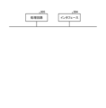
- FIG. 9 is a block diagram illustrating an example of a hardware configuration that implements the functions of the control unit 30 according to the first embodiment.
- FIG. 10 is a block diagram showing another example of the hardware configuration that implements the functions of the control unit 30 according to the first embodiment.
- a processor 300 that performs calculations
- a memory 302 that stores a program read by the processor 300
- an interface 304 for inputting and outputting signals.
- the processor 300 is an example of an arithmetic unit called an arithmetic device, a microprocessor, a microcomputer, a CPU (Central Processing Unit), or a DSP (Digital Signal Processor).
- the memory 302 also includes RAM (Random Access Memory), ROM (Read Only Memory), flash memory, EPROM (Erasable Programmable ROM), and EEPROM (registered trademark) (Electric Memory). non-volatile or volatile semiconductor memory such as Cally EPROM), Examples include a magnetic disk, a flexible disk, an optical disk, a compact disk, a mini disk, and a DVD (Digital Versatile Disc).
- the memory 302 stores a program that executes the functions of the control unit 30 according to the first embodiment.
- the processor 300 performs the above-described processing by exchanging necessary information via the interface 304, executing the program stored in the memory 302, and referring to the table stored in the memory 302. It can be carried out.
- the results of calculations by processor 300 can be stored in memory 302.
- the processing circuit 305 shown in FIG. 10 can also be used.
- the processing circuit 305 is a single circuit, a composite circuit, an ASIC (Application Specific Integrated Circuit), an FPGA (Field-Programmable Gate Array), or a combination thereof.
- Information input to processing circuit 305 and information output from processing circuit 305 can be obtained via interface 304 .
- control unit 30 may be performed by the processing circuit 305, and processing that is not performed by the processing circuit 305 may be performed by the processor 300 and the memory 302.
- the drive device includes a boost converter, an inverter, a connection switching device that switches the windings of the motor between the first connection and the second connection, the boost converter, It includes a control unit that controls the inverter and the connection switching device.
- the control unit performs zero current control in which the winding connections are switched with the motor current being zero.
- the control unit switches the connection to the first connection. Make the switch. This allows the winding connections to be switched even while the motor is rotating. Further, it is possible to suppress overvoltage that may occur in the internal circuit of the drive device, regardless of the load state at the time of switching the wiring connections.
- the control unit is configured such that in a state where the first connection is selected by the connection switching device, the bus voltage is the first voltage value, and the rotation speed of the motor is the first connection.
- the bus voltage is higher than the first voltage value and the current flowing through the motor is less than or equal to a predetermined threshold value, the first connection Switching to the second connection is performed.
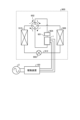
- FIG. 11 is a diagram showing a configuration example of a refrigeration cycle device 900 according to the second embodiment.
- a refrigeration cycle device 900 according to the second embodiment includes the drive device 100 described in the first embodiment.
- the refrigeration cycle device 900 according to the second embodiment can be applied to products including a refrigeration cycle, such as air conditioners, refrigerators, freezers, and heat pump water heaters. Note that in FIG. 11, components having the same functions as in the first embodiment are given the same reference numerals as in the first embodiment.
- a compressor 901 incorporating the electric motor 1 in the first embodiment, a four-way valve 902, an indoor heat exchanger 906, an expansion valve 908, and an outdoor heat exchanger 910 are connected via a refrigerant pipe 912. installed.
- a compression mechanism 904 that compresses refrigerant and an electric motor 1 that operates the compression mechanism 904 are provided inside the compressor 901.
- the refrigeration cycle device 900 can perform heating operation or cooling operation by switching the four-way valve 902.
- the compression mechanism 904 is driven by the electric motor 1 that is controlled at variable speed.
- the refrigerant is pressurized by the compression mechanism 904 and sent out, passing through the four-way valve 902, indoor heat exchanger 906, expansion valve 908, outdoor heat exchanger 910, and four-way valve 902. Returning to the compression mechanism 904.
- the refrigerant is pressurized by the compression mechanism 904 and sent out, passing through the four-way valve 902, the outdoor heat exchanger 910, the expansion valve 908, the indoor heat exchanger 906, and the four-way valve 902, as shown by the dashed arrow. Returning to the compression mechanism 904.
- the indoor heat exchanger 906 acts as a condenser and releases heat, and the outdoor heat exchanger 910 acts as an evaporator and absorbs heat.
- the outdoor heat exchanger 910 acts as a condenser and releases heat, and the indoor heat exchanger 906 acts as an evaporator and absorbs heat.
- the expansion valve 908 reduces the pressure of the refrigerant and expands it.
- the refrigeration cycle device 900 according to the second embodiment is equipped with the drive device 100 according to the first embodiment, it can enjoy the effects obtained in the first embodiment.
Landscapes
- Engineering & Computer Science (AREA)
- Power Engineering (AREA)
- Control Of Ac Motors In General (AREA)
Priority Applications (2)
| Application Number | Priority Date | Filing Date | Title |
|---|---|---|---|
| PCT/JP2022/019525 WO2023214453A1 (ja) | 2022-05-02 | 2022-05-02 | 駆動装置及び冷凍サイクル装置 |
| JP2024519155A JP7603884B2 (ja) | 2022-05-02 | 2022-05-02 | 駆動装置及び冷凍サイクル装置 |
Applications Claiming Priority (1)
| Application Number | Priority Date | Filing Date | Title |
|---|---|---|---|
| PCT/JP2022/019525 WO2023214453A1 (ja) | 2022-05-02 | 2022-05-02 | 駆動装置及び冷凍サイクル装置 |
Publications (1)
| Publication Number | Publication Date |
|---|---|
| WO2023214453A1 true WO2023214453A1 (ja) | 2023-11-09 |
Family
ID=88646397
Family Applications (1)
| Application Number | Title | Priority Date | Filing Date |
|---|---|---|---|
| PCT/JP2022/019525 Ceased WO2023214453A1 (ja) | 2022-05-02 | 2022-05-02 | 駆動装置及び冷凍サイクル装置 |
Country Status (2)
| Country | Link |
|---|---|
| JP (1) | JP7603884B2 (https=) |
| WO (1) | WO2023214453A1 (https=) |
Citations (3)
| Publication number | Priority date | Publication date | Assignee | Title |
|---|---|---|---|---|
| JP2018170919A (ja) * | 2017-03-30 | 2018-11-01 | アイシン・エィ・ダブリュ株式会社 | 車両用駆動制御装置 |
| WO2020016972A1 (ja) * | 2018-07-18 | 2020-01-23 | 三菱電機株式会社 | 回転機制御装置、冷媒圧縮装置、冷凍サイクル装置及び空気調和機 |
| WO2021210129A1 (ja) * | 2020-04-16 | 2021-10-21 | 三菱電機株式会社 | 駆動装置及び空気調和装置 |
-
2022
- 2022-05-02 WO PCT/JP2022/019525 patent/WO2023214453A1/ja not_active Ceased
- 2022-05-02 JP JP2024519155A patent/JP7603884B2/ja active Active
Patent Citations (3)
| Publication number | Priority date | Publication date | Assignee | Title |
|---|---|---|---|---|
| JP2018170919A (ja) * | 2017-03-30 | 2018-11-01 | アイシン・エィ・ダブリュ株式会社 | 車両用駆動制御装置 |
| WO2020016972A1 (ja) * | 2018-07-18 | 2020-01-23 | 三菱電機株式会社 | 回転機制御装置、冷媒圧縮装置、冷凍サイクル装置及び空気調和機 |
| WO2021210129A1 (ja) * | 2020-04-16 | 2021-10-21 | 三菱電機株式会社 | 駆動装置及び空気調和装置 |
Also Published As
| Publication number | Publication date |
|---|---|
| JPWO2023214453A1 (https=) | 2023-11-09 |
| JP7603884B2 (ja) | 2024-12-20 |
Similar Documents
| Publication | Publication Date | Title |
|---|---|---|
| JP5907712B2 (ja) | モータ駆動装置、およびこれを用いた機器 | |
| CN112400276B (zh) | 旋转机控制装置、制冷剂压缩装置、制冷环路装置以及空调机 | |
| JP2009216324A (ja) | 空気調和機 | |
| WO2016051456A1 (ja) | 巻線切替モータ駆動装置、巻線切替モータの駆動制御方法、及びそれらを用いた冷凍空調機器 | |
| JP6235381B2 (ja) | 圧縮機 | |
| WO2020021681A1 (ja) | 電動機駆動装置及び冷凍サイクル適用機器 | |
| JPH05272823A (ja) | 能力可変型空気調和装置の制御方法 | |
| JP7258235B2 (ja) | 駆動装置及び空気調和装置 | |
| WO2019229914A1 (ja) | 室外機及び冷凍サイクル装置 | |
| JP6991364B2 (ja) | モータ駆動装置、冷凍サイクル装置、空気調和機、給湯機及び冷蔵庫 | |
| JP4595372B2 (ja) | 圧縮機、圧縮機駆動制御装置および圧縮機の駆動制御方法 | |
| JP7603884B2 (ja) | 駆動装置及び冷凍サイクル装置 | |
| JP7325526B2 (ja) | 電動機駆動装置、冷凍サイクル装置、空気調和機、給湯機、及び冷蔵庫 | |
| JP7115360B2 (ja) | 電動圧縮機 | |
| JP7069400B2 (ja) | 電動機駆動装置及び空気調和機 | |
| JP7270841B2 (ja) | 電動機駆動装置及び空気調和機 | |
| EP4300810B1 (en) | Electric motor drive device and refrigeration cycle application device | |
| JP7486656B2 (ja) | 電動機駆動装置、冷凍サイクル装置、空気調和機、給湯器および冷蔵庫 | |
| JP5747145B2 (ja) | モータ駆動装置およびこれを用いた電気機器 | |
| JP2013225979A (ja) | モータ駆動装置、及びそれを適用した圧縮機駆動装置、並びにそれを備えた熱交換器 | |
| JP2022125083A (ja) | モータ駆動装置及び空気調和機 | |
| JP2001003864A (ja) | 空気調和装置 | |
| WO2023175893A1 (ja) | 駆動装置及び空気調和装置 |
Legal Events
| Date | Code | Title | Description |
|---|---|---|---|
| 121 | Ep: the epo has been informed by wipo that ep was designated in this application |
Ref document number: 22940814 Country of ref document: EP Kind code of ref document: A1 |
|
| WWE | Wipo information: entry into national phase |
Ref document number: 2024519155 Country of ref document: JP |
|
| NENP | Non-entry into the national phase |
Ref country code: DE |
|
| 122 | Ep: pct application non-entry in european phase |
Ref document number: 22940814 Country of ref document: EP Kind code of ref document: A1 |