WO2023210646A1 - バッテリマネジメントシステム - Google Patents
バッテリマネジメントシステム Download PDFInfo
- Publication number
- WO2023210646A1 WO2023210646A1 PCT/JP2023/016322 JP2023016322W WO2023210646A1 WO 2023210646 A1 WO2023210646 A1 WO 2023210646A1 JP 2023016322 W JP2023016322 W JP 2023016322W WO 2023210646 A1 WO2023210646 A1 WO 2023210646A1
- Authority
- WO
- WIPO (PCT)
- Prior art keywords
- circuit
- cmu
- bmu
- battery
- wireless communication
- Prior art date
- Legal status (The legal status is an assumption and is not a legal conclusion. Google has not performed a legal analysis and makes no representation as to the accuracy of the status listed.)
- Ceased
Links
Images




Classifications
-
- H—ELECTRICITY
- H02—GENERATION; CONVERSION OR DISTRIBUTION OF ELECTRIC POWER
- H02J—ELECTRIC POWER NETWORKS; CIRCUIT ARRANGEMENTS OR SYSTEMS FOR SUPPLYING OR DISTRIBUTING ELECTRIC POWER; SYSTEMS FOR STORING ELECTRIC ENERGY
- H02J50/00—Circuit arrangements or systems for wireless supply or distribution of electric power
- H02J50/20—Circuit arrangements or systems for wireless supply or distribution of electric power using microwaves or radio frequency waves
-
- G—PHYSICS
- G01—MEASURING; TESTING
- G01R—MEASURING ELECTRIC VARIABLES; MEASURING MAGNETIC VARIABLES
- G01R31/00—Arrangements for testing electric properties; Arrangements for locating electric faults; Arrangements for electrical testing characterised by what is being tested not provided for elsewhere
- G01R31/36—Arrangements for testing, measuring or monitoring the electrical condition of accumulators or electric batteries, e.g. capacity or state of charge [SoC]
-
- G—PHYSICS
- G01—MEASURING; TESTING
- G01R—MEASURING ELECTRIC VARIABLES; MEASURING MAGNETIC VARIABLES
- G01R31/00—Arrangements for testing electric properties; Arrangements for locating electric faults; Arrangements for electrical testing characterised by what is being tested not provided for elsewhere
- G01R31/36—Arrangements for testing, measuring or monitoring the electrical condition of accumulators or electric batteries, e.g. capacity or state of charge [SoC]
- G01R31/371—Arrangements for testing, measuring or monitoring the electrical condition of accumulators or electric batteries, e.g. capacity or state of charge [SoC] with remote indication, e.g. on external chargers
-
- G—PHYSICS
- G01—MEASURING; TESTING
- G01R—MEASURING ELECTRIC VARIABLES; MEASURING MAGNETIC VARIABLES
- G01R31/00—Arrangements for testing electric properties; Arrangements for locating electric faults; Arrangements for electrical testing characterised by what is being tested not provided for elsewhere
- G01R31/36—Arrangements for testing, measuring or monitoring the electrical condition of accumulators or electric batteries, e.g. capacity or state of charge [SoC]
- G01R31/382—Arrangements for monitoring battery or accumulator variables, e.g. SoC
-
- G—PHYSICS
- G01—MEASURING; TESTING
- G01R—MEASURING ELECTRIC VARIABLES; MEASURING MAGNETIC VARIABLES
- G01R31/00—Arrangements for testing electric properties; Arrangements for locating electric faults; Arrangements for electrical testing characterised by what is being tested not provided for elsewhere
- G01R31/36—Arrangements for testing, measuring or monitoring the electrical condition of accumulators or electric batteries, e.g. capacity or state of charge [SoC]
- G01R31/396—Acquisition or processing of data for testing or for monitoring individual cells or groups of cells within a battery
-
- G—PHYSICS
- G06—COMPUTING OR CALCULATING; COUNTING
- G06T—IMAGE DATA PROCESSING OR GENERATION, IN GENERAL
- G06T7/00—Image analysis
- G06T7/70—Determining position or orientation of objects or cameras
-
- H—ELECTRICITY
- H01—ELECTRIC ELEMENTS
- H01M—PROCESSES OR MEANS, e.g. BATTERIES, FOR THE DIRECT CONVERSION OF CHEMICAL ENERGY INTO ELECTRICAL ENERGY
- H01M10/00—Secondary cells; Manufacture thereof
- H01M10/42—Methods or arrangements for servicing or maintenance of secondary cells or secondary half-cells
-
- H—ELECTRICITY
- H01—ELECTRIC ELEMENTS
- H01M—PROCESSES OR MEANS, e.g. BATTERIES, FOR THE DIRECT CONVERSION OF CHEMICAL ENERGY INTO ELECTRICAL ENERGY
- H01M10/00—Secondary cells; Manufacture thereof
- H01M10/42—Methods or arrangements for servicing or maintenance of secondary cells or secondary half-cells
- H01M10/425—Structural combination with electronic components, e.g. electronic circuits integrated to the outside of the casing
-
- H—ELECTRICITY
- H01—ELECTRIC ELEMENTS
- H01M—PROCESSES OR MEANS, e.g. BATTERIES, FOR THE DIRECT CONVERSION OF CHEMICAL ENERGY INTO ELECTRICAL ENERGY
- H01M10/00—Secondary cells; Manufacture thereof
- H01M10/42—Methods or arrangements for servicing or maintenance of secondary cells or secondary half-cells
- H01M10/48—Accumulators combined with arrangements for measuring, testing or indicating the condition of cells, e.g. the level or density of the electrolyte
-
- H—ELECTRICITY
- H01—ELECTRIC ELEMENTS
- H01M—PROCESSES OR MEANS, e.g. BATTERIES, FOR THE DIRECT CONVERSION OF CHEMICAL ENERGY INTO ELECTRICAL ENERGY
- H01M10/00—Secondary cells; Manufacture thereof
- H01M10/42—Methods or arrangements for servicing or maintenance of secondary cells or secondary half-cells
- H01M10/48—Accumulators combined with arrangements for measuring, testing or indicating the condition of cells, e.g. the level or density of the electrolyte
- H01M10/482—Accumulators combined with arrangements for measuring, testing or indicating the condition of cells, e.g. the level or density of the electrolyte for several batteries or cells simultaneously or sequentially
-
- H—ELECTRICITY
- H01—ELECTRIC ELEMENTS
- H01M—PROCESSES OR MEANS, e.g. BATTERIES, FOR THE DIRECT CONVERSION OF CHEMICAL ENERGY INTO ELECTRICAL ENERGY
- H01M50/00—Constructional details or processes of manufacture of the non-active parts of electrochemical cells other than fuel cells, e.g. hybrid cells
- H01M50/20—Mountings; Secondary casings or frames; Racks, modules or packs; Suspension devices; Shock absorbers; Transport or carrying devices; Holders
- H01M50/204—Racks, modules or packs for multiple batteries or multiple cells
- H01M50/207—Racks, modules or packs for multiple batteries or multiple cells characterised by their shape
- H01M50/209—Racks, modules or packs for multiple batteries or multiple cells characterised by their shape adapted for prismatic or rectangular cells
-
- H—ELECTRICITY
- H01—ELECTRIC ELEMENTS
- H01M—PROCESSES OR MEANS, e.g. BATTERIES, FOR THE DIRECT CONVERSION OF CHEMICAL ENERGY INTO ELECTRICAL ENERGY
- H01M50/00—Constructional details or processes of manufacture of the non-active parts of electrochemical cells other than fuel cells, e.g. hybrid cells
- H01M50/20—Mountings; Secondary casings or frames; Racks, modules or packs; Suspension devices; Shock absorbers; Transport or carrying devices; Holders
- H01M50/249—Mountings; Secondary casings or frames; Racks, modules or packs; Suspension devices; Shock absorbers; Transport or carrying devices; Holders specially adapted for aircraft or vehicles, e.g. cars or trains
-
- H—ELECTRICITY
- H01—ELECTRIC ELEMENTS
- H01M—PROCESSES OR MEANS, e.g. BATTERIES, FOR THE DIRECT CONVERSION OF CHEMICAL ENERGY INTO ELECTRICAL ENERGY
- H01M50/00—Constructional details or processes of manufacture of the non-active parts of electrochemical cells other than fuel cells, e.g. hybrid cells
- H01M50/20—Mountings; Secondary casings or frames; Racks, modules or packs; Suspension devices; Shock absorbers; Transport or carrying devices; Holders
- H01M50/271—Lids or covers for the racks or secondary casings
-
- H—ELECTRICITY
- H01—ELECTRIC ELEMENTS
- H01Q—ANTENNAS, i.e. RADIO AERIALS
- H01Q1/00—Details of, or arrangements associated with, antennas
- H01Q1/12—Supports; Mounting means
- H01Q1/22—Supports; Mounting means by structural association with other equipment or articles
-
- H—ELECTRICITY
- H02—GENERATION; CONVERSION OR DISTRIBUTION OF ELECTRIC POWER
- H02J—ELECTRIC POWER NETWORKS; CIRCUIT ARRANGEMENTS OR SYSTEMS FOR SUPPLYING OR DISTRIBUTING ELECTRIC POWER; SYSTEMS FOR STORING ELECTRIC ENERGY
- H02J50/00—Circuit arrangements or systems for wireless supply or distribution of electric power
- H02J50/10—Circuit arrangements or systems for wireless supply or distribution of electric power using inductive coupling
-
- H—ELECTRICITY
- H02—GENERATION; CONVERSION OR DISTRIBUTION OF ELECTRIC POWER
- H02J—ELECTRIC POWER NETWORKS; CIRCUIT ARRANGEMENTS OR SYSTEMS FOR SUPPLYING OR DISTRIBUTING ELECTRIC POWER; SYSTEMS FOR STORING ELECTRIC ENERGY
- H02J7/00—Circuit arrangements for charging or discharging batteries or for supplying loads from batteries
-
- H—ELECTRICITY
- H02—GENERATION; CONVERSION OR DISTRIBUTION OF ELECTRIC POWER
- H02J—ELECTRIC POWER NETWORKS; CIRCUIT ARRANGEMENTS OR SYSTEMS FOR SUPPLYING OR DISTRIBUTING ELECTRIC POWER; SYSTEMS FOR STORING ELECTRIC ENERGY
- H02J7/00—Circuit arrangements for charging or discharging batteries or for supplying loads from batteries
- H02J7/02—Circuit arrangements for charging or discharging batteries or for supplying loads from batteries for charging batteries from AC mains by converters
-
- H—ELECTRICITY
- H02—GENERATION; CONVERSION OR DISTRIBUTION OF ELECTRIC POWER
- H02J—ELECTRIC POWER NETWORKS; CIRCUIT ARRANGEMENTS OR SYSTEMS FOR SUPPLYING OR DISTRIBUTING ELECTRIC POWER; SYSTEMS FOR STORING ELECTRIC ENERGY
- H02J7/00—Circuit arrangements for charging or discharging batteries or for supplying loads from batteries
- H02J7/40—Circuit arrangements for charging or discharging batteries or for supplying loads from batteries characterised by the exchange of charge or discharge related data
-
- H—ELECTRICITY
- H02—GENERATION; CONVERSION OR DISTRIBUTION OF ELECTRIC POWER
- H02J—ELECTRIC POWER NETWORKS; CIRCUIT ARRANGEMENTS OR SYSTEMS FOR SUPPLYING OR DISTRIBUTING ELECTRIC POWER; SYSTEMS FOR STORING ELECTRIC ENERGY
- H02J7/00—Circuit arrangements for charging or discharging batteries or for supplying loads from batteries
- H02J7/50—Circuit arrangements for charging or discharging batteries or for supplying loads from batteries acting upon multiple batteries simultaneously or sequentially
-
- H—ELECTRICITY
- H02—GENERATION; CONVERSION OR DISTRIBUTION OF ELECTRIC POWER
- H02J—ELECTRIC POWER NETWORKS; CIRCUIT ARRANGEMENTS OR SYSTEMS FOR SUPPLYING OR DISTRIBUTING ELECTRIC POWER; SYSTEMS FOR STORING ELECTRIC ENERGY
- H02J7/00—Circuit arrangements for charging or discharging batteries or for supplying loads from batteries
- H02J7/80—Circuit arrangements for charging or discharging batteries or for supplying loads from batteries including monitoring or indicating arrangements
-
- H—ELECTRICITY
- H02—GENERATION; CONVERSION OR DISTRIBUTION OF ELECTRIC POWER
- H02J—ELECTRIC POWER NETWORKS; CIRCUIT ARRANGEMENTS OR SYSTEMS FOR SUPPLYING OR DISTRIBUTING ELECTRIC POWER; SYSTEMS FOR STORING ELECTRIC ENERGY
- H02J7/00—Circuit arrangements for charging or discharging batteries or for supplying loads from batteries
- H02J7/80—Circuit arrangements for charging or discharging batteries or for supplying loads from batteries including monitoring or indicating arrangements
- H02J7/82—Control of state of charge [SOC]
-
- H—ELECTRICITY
- H04—ELECTRIC COMMUNICATION TECHNIQUE
- H04L—TRANSMISSION OF DIGITAL INFORMATION, e.g. TELEGRAPHIC COMMUNICATION
- H04L5/00—Arrangements affording multiple use of the transmission path
- H04L5/0001—Arrangements for dividing the transmission path
- H04L5/0003—Two-dimensional division
- H04L5/0005—Time-frequency
- H04L5/0007—Time-frequency the frequencies being orthogonal, e.g. OFDM(A) or DMT
-
- B—PERFORMING OPERATIONS; TRANSPORTING
- B60—VEHICLES IN GENERAL
- B60L—PROPULSION OF ELECTRICALLY-PROPELLED VEHICLES; SUPPLYING ELECTRIC POWER FOR AUXILIARY EQUIPMENT OF ELECTRICALLY-PROPELLED VEHICLES; ELECTRODYNAMIC BRAKE SYSTEMS FOR VEHICLES IN GENERAL; MAGNETIC SUSPENSION OR LEVITATION FOR VEHICLES; MONITORING OPERATING VARIABLES OF ELECTRICALLY-PROPELLED VEHICLES; ELECTRIC SAFETY DEVICES FOR ELECTRICALLY-PROPELLED VEHICLES
- B60L58/00—Methods or circuit arrangements for monitoring or controlling batteries or fuel cells, specially adapted for electric vehicles
- B60L58/10—Methods or circuit arrangements for monitoring or controlling batteries or fuel cells, specially adapted for electric vehicles for monitoring or controlling batteries
-
- H—ELECTRICITY
- H01—ELECTRIC ELEMENTS
- H01M—PROCESSES OR MEANS, e.g. BATTERIES, FOR THE DIRECT CONVERSION OF CHEMICAL ENERGY INTO ELECTRICAL ENERGY
- H01M10/00—Secondary cells; Manufacture thereof
- H01M10/42—Methods or arrangements for servicing or maintenance of secondary cells or secondary half-cells
- H01M10/425—Structural combination with electronic components, e.g. electronic circuits integrated to the outside of the casing
- H01M2010/4271—Battery management systems including electronic circuits, e.g. control of current or voltage to keep battery in healthy state, cell balancing
-
- H—ELECTRICITY
- H01—ELECTRIC ELEMENTS
- H01M—PROCESSES OR MEANS, e.g. BATTERIES, FOR THE DIRECT CONVERSION OF CHEMICAL ENERGY INTO ELECTRICAL ENERGY
- H01M10/00—Secondary cells; Manufacture thereof
- H01M10/42—Methods or arrangements for servicing or maintenance of secondary cells or secondary half-cells
- H01M10/425—Structural combination with electronic components, e.g. electronic circuits integrated to the outside of the casing
- H01M2010/4278—Systems for data transfer from batteries, e.g. transfer of battery parameters to a controller, data transferred between battery controller and main controller
-
- H—ELECTRICITY
- H01—ELECTRIC ELEMENTS
- H01M—PROCESSES OR MEANS, e.g. BATTERIES, FOR THE DIRECT CONVERSION OF CHEMICAL ENERGY INTO ELECTRICAL ENERGY
- H01M2220/00—Batteries for particular applications
- H01M2220/20—Batteries in motive systems, e.g. vehicle, ship, plane
-
- H—ELECTRICITY
- H01—ELECTRIC ELEMENTS
- H01P—WAVEGUIDES; RESONATORS, LINES, OR OTHER DEVICES OF THE WAVEGUIDE TYPE
- H01P3/00—Waveguides; Transmission lines of the waveguide type
- H01P3/12—Hollow waveguides
-
- H—ELECTRICITY
- H02—GENERATION; CONVERSION OR DISTRIBUTION OF ELECTRIC POWER
- H02J—ELECTRIC POWER NETWORKS; CIRCUIT ARRANGEMENTS OR SYSTEMS FOR SUPPLYING OR DISTRIBUTING ELECTRIC POWER; SYSTEMS FOR STORING ELECTRIC ENERGY
- H02J2105/00—Networks for supplying or distributing electric power characterised by their spatial reach or by the load
- H02J2105/30—Networks for supplying or distributing electric power characterised by their spatial reach or by the load the load networks being external to vehicles, i.e. exchanging power with vehicles
- H02J2105/33—Networks for supplying or distributing electric power characterised by their spatial reach or by the load the load networks being external to vehicles, i.e. exchanging power with vehicles exchanging power with road vehicles
- H02J2105/37—Networks for supplying or distributing electric power characterised by their spatial reach or by the load the load networks being external to vehicles, i.e. exchanging power with vehicles exchanging power with road vehicles exchanging power with electric vehicles [EV] or with hybrid electric vehicles [HEV]
-
- Y—GENERAL TAGGING OF NEW TECHNOLOGICAL DEVELOPMENTS; GENERAL TAGGING OF CROSS-SECTIONAL TECHNOLOGIES SPANNING OVER SEVERAL SECTIONS OF THE IPC; TECHNICAL SUBJECTS COVERED BY FORMER USPC CROSS-REFERENCE ART COLLECTIONS [XRACs] AND DIGESTS
- Y02—TECHNOLOGIES OR APPLICATIONS FOR MITIGATION OR ADAPTATION AGAINST CLIMATE CHANGE
- Y02E—REDUCTION OF GREENHOUSE GAS [GHG] EMISSIONS, RELATED TO ENERGY GENERATION, TRANSMISSION OR DISTRIBUTION
- Y02E60/00—Enabling technologies; Technologies with a potential or indirect contribution to GHG emissions mitigation
- Y02E60/10—Energy storage using batteries
Definitions
- the present disclosure relates to a battery management system for managing assembled batteries.
- Patent Document 1 discloses a technique for managing a plurality of battery cells that constitute an assembled battery.
- communication is performed between a management circuit that manages an assembled battery and a plurality of monitoring circuits that monitor the assembled battery.
- communication may fail due to disconnection of the communication line, external noise, communication interaction between the management circuit and each of the plurality of monitoring circuits, or the like.
- the present disclosure provides a battery management system that can increase communication redundancy within the battery management system.
- a battery management system is a battery management system for managing an assembled battery, and includes a management circuit that manages the assembled battery, and a first circuit that monitors one or more battery cells that constitute the assembled battery. a cell monitoring circuit; and a second cell monitoring circuit that monitors the one or more battery cells monitored by the first cell monitoring circuit, and the first cell monitoring circuit communicates with the management circuit.
- the second cell monitoring circuit includes a power line communication circuit using a power line in the assembled battery to communicate with the management circuit.
- a battery management system is a battery management system for managing an assembled battery, and includes a management circuit that manages the assembled battery, and a plurality of cells that monitor one or more battery cells forming the assembled battery. a monitoring circuit, each of the plurality of cell monitoring circuits is connected to another cell monitoring circuit through wired communication, and at least two of the plurality of cell monitoring circuits communicate with the management circuit. It is equipped with a wireless communication circuit and a communication antenna.
- redundancy of communication within the battery management system can be increased.
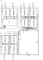
- FIG. 1 is an external view showing an example of a battery management system according to an embodiment.
- FIG. 1 is a configuration diagram showing a first example of a battery management system according to an embodiment.
- FIG. 2 is a configuration diagram showing an example of a wireless communication circuit included in a first cell monitoring circuit.
- FIG. 2 is a configuration diagram showing an example of a voltage monitoring circuit included in a first cell monitoring circuit.
- FIG. 3 is a configuration diagram showing an example of a power line communication circuit included in a second cell monitoring circuit.
- FIG. 3 is a configuration diagram showing an example of a voltage monitoring circuit included in a second cell monitoring circuit.
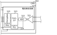
- FIG. 2 is a configuration diagram showing an example of a current measurement circuit included in the current monitoring circuit.
- FIG. 1 is an external view showing an example of a battery management system according to an embodiment.
- FIG. 1 is a configuration diagram showing a first example of a battery management system according to an embodiment.
- FIG. 2 is a configuration diagram showing an example of a wireless communication circuit
- FIG. 2 is a configuration diagram showing an example of a wireless communication circuit included in the management circuit.
- FIG. 2 is a configuration diagram showing an example of a power line communication circuit included in the management circuit. It is a block diagram which shows an example of MCU with which a management circuit is provided. It is a block diagram which shows the 2nd example of the battery management system based on embodiment.
- FIG. 3 is a configuration diagram showing an example of a current measurement circuit included in the first current monitoring circuit.
- FIG. 2 is a configuration diagram showing an example of a wireless communication circuit included in the first current monitoring circuit. It is a block diagram which shows the 3rd example of the battery management system based on embodiment. It is a block diagram which shows the 4th example of the battery management system based on embodiment. It is a block diagram which shows the 5th example of the battery management system based on embodiment.
- FIG. 1 is an external view showing an example of a battery management system 1 (hereinafter also referred to as BMS (Battery Management System) 1) according to an embodiment.
- BMS Battery Management System
- the BMS1 is a system for managing assembled batteries.
- the BMS 1 manages the SOC (State of Charge), SOH (State of Health), SOP (State of Power), etc. of the assembled battery.
- the BMS 1 also monitors the assembled battery for abnormalities.
- the BMS 1 includes a management circuit 200 that manages assembled batteries, and a plurality of monitoring circuits 100 that monitors the assembled batteries.
- a battery pack is configured by connecting a plurality of battery packs 10 in series or in parallel.
- the battery pack 10 is comprised of one or more battery cells. When the battery pack 10 is composed of a plurality of battery cells, the plurality of battery cells are connected in series.
- the monitoring circuit 100 is placed on each of the plurality of battery packs 10.
- the management circuit 200 is connected to the assembled battery via the connection box 20.
- BMUs Battery Management Units
- 201 to 203 which are specific examples of the management circuit 200, will be described later.
- FIG. 2 is a configuration diagram showing a first example of the BMS 1 according to the embodiment.
- FIG. 3A is a configuration diagram showing an example of the wireless communication circuit 111 included in the first cell monitoring circuit (CMU 101). Note that FIG. 3A also shows the peripheral portion of the wireless communication circuit 111 in the configuration diagram of FIG. 2.
- FIG. 3B is a configuration diagram showing an example of the voltage monitoring circuit 112 included in the first cell monitoring circuit (CMU 101). Note that FIG. 3B also shows the peripheral portion of the voltage monitoring circuit 112 in the configuration diagram of FIG. 2.
- FIG. 4A is a configuration diagram showing an example of the power line communication circuit 113 included in the second cell monitoring circuit (CMU 102). Note that FIG. 4A also shows the peripheral portion of the power line communication circuit 113 in the configuration diagram of FIG. 2.
- FIG. 4B is a configuration diagram showing an example of the voltage monitoring circuit 114 included in the second cell monitoring circuit (CMU 102). Note that FIG. 4B also shows the peripheral portion of the voltage monitoring circuit 114 in the configuration diagram of FIG. 2.
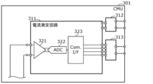
- FIG. 5 is a configuration diagram showing an example of the current measurement circuit 311 included in the current monitoring circuit (CMU 301). Note that FIG. 5 also shows the peripheral portion of the current measurement circuit 311 in the configuration diagram of FIG. 2.
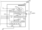
- FIG. 6A is a configuration diagram showing an example of the wireless communication circuit 211 included in the management circuit (BMU 201). Note that FIG. 6A also shows the peripheral portion of the wireless communication circuit 211 in the configuration diagram of FIG. 2.
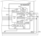
- FIG. 6B is a configuration diagram showing an example of the power line communication circuit 212 included in the management circuit (BMU 201). Note that FIG. 6B also shows the peripheral portion of the power line communication circuit 212 in the configuration diagram of FIG. 2.
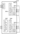
- FIG. 6C is a configuration diagram showing an example of the MCU 213 included in the management circuit (BMU 201). Note that FIG. 6C also shows the peripheral portion of the MCU 213 in the configuration diagram of FIG. 2.
- one battery pack 10 among the plurality of battery packs 10 attention is focused on one battery pack 10 among the plurality of battery packs 10, and one or more battery cells forming the assembled battery include a plurality of batteries forming one battery pack 10 in the assembled battery.
- Cell 11 is shown in FIG.
- the monitoring circuit 100 the CMUs 101 and 102 and the CMU 301 are shown, and as the management circuit 200, the BMU 201 is shown.
- a motor 400 is shown as a load to which power is supplied from the assembled battery, a power line 405 (bus bar) connecting the assembled battery and the motor 400, a relay 401 inserted into the power line 405, and a shunt resistor 402 are shown. ing.
- the relay 401 is a switch for cutting off the current flowing through the power line 405. For example, the relay 401 is turned off to cut off the current flowing through the power line 405 when the current monitored by the CMU 301 is determined to be abnormal. Further, for example, the relay 401 is turned off to cut off the current flowing through the power line 405 when the voltage monitored by the CMU 101 or 102 is determined to be abnormal.
- the shunt resistor 402 is a resistor for measuring the current flowing through the power line 405.
- the CMU 101 is an example of a first cell monitoring circuit that monitors one or more battery cells that constitute a battery pack. For example, the CMU 101 monitors the voltage of each of the plurality of battery cells 11.
- CMU 102 is an example of a second cell monitoring circuit that monitors one or more battery cells monitored by the first cell monitoring circuit. For example, the CMU 102 monitors the voltage of each of the plurality of battery cells 11 that the CMU 101 monitors.
- the CMU 101 and the CMU 102 each monitor the same battery cell 11.
- the CMU 101 includes a wireless communication circuit 111 and a communication antenna ANT1 for communicating with the BMU 201.
- the CMU 101 also includes a voltage monitoring circuit 112 that monitors the voltage of each of the plurality of battery cells 11.
- the wireless communication circuit 111 and the voltage monitoring circuit 112 are each realized by different ICs (Integrated Circuits). Note that the wireless communication circuit 111 and the voltage monitoring circuit 112 may be realized by one IC.
- the wireless communication circuit 111 includes a voltage conversion circuit (Reg.) 121, a timer circuit (Timer) 122, a communication interface (Com.I/F) 123, a clock generation circuit (Clockgen) 124, Phase locked loop (PLL) 125, modulation circuit (Modulator) 126, transmission circuit (Tx) 127, demodulation circuit (Demodulator) 128, reception circuit (Rx) 129, non-volatile memory (NVM) 130, communication error determination circuit (RF) Error) 131 and a wake up circuit 132.
- a voltage conversion circuit (Reg.) 121
- Timer timer circuit
- Communication interface Com.I/F
- PLL Phase locked loop
- Modulator Modulator
- Tx transmission circuit
- Demodulator demodulation circuit
- Rx non-volatile memory
- RF communication error determination circuit
- RF communication error determination circuit
- the voltage conversion circuit 121 is a circuit that converts the voltage input from the voltage monitoring circuit 112 into a voltage for operating the wireless communication circuit 111 and outputs the voltage.
- the timer circuit 122 is a circuit that counts time.
- the timer circuit 122 is used to cause the wireless communication circuit 111 to operate intermittently.
- the communication interface 123 is an interface for communicating between the wireless communication circuit 111 and the voltage monitoring circuit 112. Note that if the wireless communication circuit 111 and the voltage monitoring circuit 112 are realized by one IC, the communication interface 123 may not be provided.
- the clock generation circuit 124 is a circuit for generating a clock in the CMU 101.
- the phase synchronization circuit 125 is a circuit that adjusts the phase of the local signal to match the phase of the received signal.
- the modulation circuit 126 is a circuit that modulates the signal transmitted to the BMU 201.
- the transmitting circuit 127 is a circuit for transmitting a signal to the BMU 201.
- Transmission circuit 127 transmits a signal to BMU 201 via communication antenna ANT1.
- the demodulation circuit 128 is a circuit that demodulates the signal received from the BMU 201.
- the receiving circuit 129 is a circuit for receiving signals from the BMU 201.
- the receiving circuit 129 receives a signal from the BMU 201 via the communication antenna ANT1.
- the nonvolatile memory 130 stores identification information of the wireless communication circuit 111.
- the nonvolatile memory 130 stores identification information "ID2A".
- FIG. 3A shows the nonvolatile memory 130, the identification information may be stored in any memory included in the wireless communication circuit 111.
- illustrations of memories in which identification information is stored are omitted.
- the communication error determination circuit 131 is a circuit that determines whether an abnormality has occurred in the communication between the CMU 101 and the BMU 201.
- the startup circuit 132 is a circuit for starting the wireless communication circuit 111.
- the CMU 101 may include an LED 133.
- the LED 133 emits light when the wireless communication circuit 111 satisfies a specific condition.
- the voltage monitoring circuit 112 includes a voltage conversion circuit (Reg.) 141, a timer circuit (Timer) 142, a multiplexer (MUX) 143, an AD converter (ADC) 144, and a communication interface (Com. F) 145, a phase locked loop (PLL) 146, an encryption circuit (Encryption) 147, and a switch 148.
- a voltage conversion circuit (Reg.) 141
- a timer circuit timer
- MUX multiplexer
- ADC AD converter
- Com. F communication interface
- PLL phase locked loop
- Encryption Encryption
- the voltage conversion circuit 141 is a circuit that converts the voltage input from the assembled battery into a voltage for operating the voltage monitoring circuit 112 and outputs the voltage.
- the timer circuit 142 is a circuit that counts time.
- the timer circuit 142 is a circuit for causing the wireless communication circuit 111 to operate intermittently. Note that although the CMU 101 includes the timer circuits 122 and 142 in the wireless communication circuit 111 and the voltage monitoring circuit 112, it is not necessary to include both the timer circuits 122 and 142. That is, the wireless communication circuit 111 does not need to include the timer circuit 122, or the voltage monitoring circuit 112 does not need to include the timer circuit 142.
- the multiplexer 143 selects one battery cell 11 from among the plurality of battery cells 11 and outputs the voltage across the selected battery cell 11. That is, the multiplexer 143 can output the respective voltages of the plurality of battery cells 11.
- the AD converter 144 converts the voltage value (analog value) of the battery cell 11 selected by the multiplexer 143 into a digital value.
- the communication interface 145 is an interface for communicating between the wireless communication circuit 111 and the voltage monitoring circuit 112. Note that if the wireless communication circuit 111 and the voltage monitoring circuit 112 are realized by one IC, the communication interface 145 may not be provided.
- the phase synchronization circuit 146 is a circuit that adjusts the phase of the local signal to match the phase of the received signal.
- the encryption circuit 147 is a circuit that encrypts and decrypts signals. For example, the encryption circuit 147 encrypts a signal transmitted to the wireless communication circuit 111 and eventually the BMU 201 using an encryption key.
- the switch 148 is a switch that turns on and off the supply of power to the wireless communication circuit 111, and is, for example, a transistor. Switch 148 is controlled by a control signal from activation circuit 132.
- the startup circuit 132 can control the startup of the wireless communication circuit 111 by controlling the switch 148 and controlling the supply of power to the wireless communication circuit 111 .
- the CMU 101 detects the voltage value of each of the plurality of battery cells 11 using the voltage monitoring circuit 112, and transmits the detected voltage value to the BMU 201 via the wireless communication circuit 111.
- the CMU 102 includes a power line communication circuit 113 that uses a power line 405 (for example, a bus bar) in an assembled battery to communicate with the BMU 201.
- the CMU 102 also includes a voltage monitoring circuit 114 that monitors the voltage of each of the plurality of battery cells 11.
- the power line communication circuit 113 and the voltage monitoring circuit 114 are realized by different ICs. Note that the power line communication circuit 113 and the voltage monitoring circuit 114 may be realized by one IC.
- the power line communication circuit 113 includes a voltage conversion circuit (Reg.) 121, a timer circuit (Timer) 122, a communication interface (Com.I/F) 123, and a clock generation circuit (Clock gen). ) 124, phase locked loop (PLL) 125, modulator 126, demodulator 128, communication error determination circuit (RF Error) 131, wake up circuit 132, amplifier circuits 134 and 135, capacitor 136 and 137 and a coil 138. Further, in FIG. 4A, “ID2B” is shown as identification information of the power line communication circuit 113.
- the amplifier circuit 134 is a circuit that amplifies the signal sent to the BMU 201.
- the amplifier circuit 135 is a circuit that amplifies the signal received from the BMU 201.
- the capacitors 136 and 137 block the DC component superimposed on the signal received from the BMU 201 via power line communication.
- the coil 138 superimposes the signal transmitted from the CMU 102 to the BMU 201 on the power line, and also extracts the signal transmitted from the BMU 201 to the CMU 102 that is superimposed on the power line.
- the CMU 102 may include an LED 133.
- the LED 133 emits light when the power line communication circuit 113 satisfies a specific condition.
- the voltage monitoring circuit 114 includes a voltage conversion circuit (Reg.) 141, a timer circuit (Timer) 142, a communication interface (Com.I/F) 145, an encryption circuit (Encryption) 147, and a switch 148. and comparators 149 to 152.
- the functions of the voltage conversion circuit 141, timer circuit 142, communication interface 145, encryption circuit 147, and switch 148 included in the voltage monitoring circuit 114 will be explained in the description of the functions included in the voltage monitoring circuit 112 described above.
- the communication circuit 113, the voltage monitoring circuit 112 are replaced with a voltage monitoring circuit 114, and the CMU 101 is replaced with a CMU 102.
- Each of the comparators 149 to 152 is provided one-to-one for each of the plurality of battery cells 11.
- four comparators 149 to 152 are shown as an example, but the number of comparators corresponds to the number of battery cells 11.
- the comparator 149 compares the voltage of the first battery cell 11 with a predetermined voltage
- the comparator 150 compares the voltage of the first battery cell 11 with a predetermined voltage
- the comparator 151 compares the voltage of the third battery cell 11 with a predetermined voltage
- the comparator 152 compares the voltage of the fourth battery cell 11 with a predetermined voltage. Compare the voltage with a predetermined voltage.
- the voltage monitoring circuit 114 can check whether each of the plurality of battery cells 11 has a predetermined voltage or higher (for example, if the voltage is overvoltage). ), or it can be determined whether each of the plurality of battery cells 11 has a predetermined voltage or less (for example, whether the voltage is too low). That is, the voltage monitoring circuit 114 can determine whether the voltage of each of the plurality of battery cells 11 is abnormal.
- the CMU 102 uses the voltage monitoring circuit 114 to determine whether the voltage of each of the plurality of battery cells 11 is abnormal, and uses the power line communication circuit 113 to transmit the determination result to the BMU 201.
- the CMU 102 may include a voltage monitoring circuit 112 instead of the voltage monitoring circuit 114. That is, the CMU 102 may detect the voltage value of each of the plurality of battery cells 11 and transmit the detected voltage value to the BMU 201. Further, the CMU 101 may include a voltage monitoring circuit 114 instead of the voltage monitoring circuit 112. That is, the CMU 101 may determine whether or not the voltage abnormality of each of the plurality of battery cells 11 is abnormal, and may transmit the determination result to the BMU 201 .
- the CMU 301 includes a current measurement circuit 311 that monitors the current flowing through the assembled battery.
- the CMU 301 also includes a power supply circuit 312 and an isolated communication circuit 313.
- the power supply circuit 312 is a circuit for supplying power to the CMU 301, and supplies the power supplied from the BMU 201 to the CMU 301. For example, power is supplied to the power supply circuit 312 from the BMU 201 via the transformer 501.
- the insulated communication circuit 313 is a circuit for communicating between the CMU 301 and BMU 201 while the CMU 301 and BMU 201 are insulated.
- the isolated communication circuit 313 can perform communication between the CMU 301 and the BMU 201 while the CMU 301 and the BMU 201 are insulated.
- the current measurement circuit 311 is a circuit that measures the current flowing through the assembled battery. Specifically, the current measurement circuit 311 measures the current flowing through the power line 405, that is, the current flowing through the assembled battery, by measuring the voltage generated when a current flows through the shunt resistor 402 provided on the power line 405. do. As shown in FIG. 5, the current measurement circuit 311 includes an amplifier circuit 321, an AD converter (ADC) 322, and a communication interface (Com.I/F) 323.
- ADC AD converter
- Com.I/F communication interface
- the amplifier circuit 321 amplifies the voltage generated across the shunt resistor 402. Since the resistance value of the shunt resistor 402 is very small and the voltage generated across the shunt resistor 402 is also small, the amplifier circuit 321 is provided.
- the AD converter 322 converts the voltage value (analog value) generated across the shunt resistor 402 into a digital value.
- the communication interface 323 is an interface for communicating between the CMU 301 and the BMU 201.
- the BMU 201 includes a wireless communication circuit 211 and a communication antenna ANT2 for communicating with the CMU 101, and a power line communication circuit 212 for communicating with the CMU 102.
- the BMU 201 also includes an MCU (Micro Controller Unit) 213 for managing the assembled battery. Note that the wireless communication circuit 211, the power line communication circuit 212, and the MCU 213 may be realized by one IC (for example, one MCU).
- the BMU 201 also includes a power supply circuit 215 and an isolated communication circuit 216.
- the power supply circuit 215 is a circuit for supplying power to the CMU 301.
- the power supply circuit 215 supplies power to the CMU 301 via the transformer 501.
- the insulated communication circuit 216 is a circuit for communicating between the CMU 301 and BMU 201 while the CMU 301 and BMU 201 are insulated.
- the isolated communication circuit 216 can perform communication between the CMU 301 and the BMU 201 while the CMU 301 and the BMU 201 are insulated.
- CMU301 monitors the current flowing through the assembled battery, which has a large voltage of several hundred volts, and handles large voltages, whereas BMU201 handles voltages of about several volts, so the difference between CMU301 and BMU201 is , and are insulated by being connected via transformers 501 and 502.
- the wireless communication circuit 211 includes a voltage conversion circuit (Reg.) 221, a timer circuit (Timer) 222, a communication interface (Com.I/F) 223, a clock generation circuit (Clockgen) 224, Phase locked loop (PLL) 225, modulation circuit (Modulator) 226, transmission circuit (Tx) 227, demodulation circuit (Demodulator) 228, reception circuit (Rx) 229, communication error determination circuit (RF Error) 231, and wake-up circuit (Wake) up) 232.
- “ID0A” is shown as identification information of the wireless communication circuit 211.
- the voltage conversion circuit 221 is a circuit that converts a voltage input from an arbitrary power source into a voltage for operating the wireless communication circuit 211 and outputs the voltage.
- the timer circuit 222 is a circuit that counts time.
- the communication interface 223 is an interface for communicating between the wireless communication circuit 211 and the MCU 213. Note that if the wireless communication circuit 211 and the MCU 213 are realized by one IC, the communication interface 223 may not be provided.
- the clock generation circuit 224 is a circuit for generating a clock in the BMU 201.
- the phase synchronization circuit 225 is a circuit that adjusts the phase of the local signal to match the phase of the received signal.
- the modulation circuit 226 is a circuit that modulates the signal transmitted to the CMU 101.
- the transmitting circuit 227 is a circuit for transmitting a signal to the CMU 101. Transmission circuit 227 transmits a signal to CMU 101 via communication antenna ANT2.
- the demodulation circuit 228 is a circuit that demodulates the signal received from the CMU 101.
- the receiving circuit 229 is a circuit for receiving signals from the CMU 101.
- the receiving circuit 229 receives a signal from the CMU 101 via the communication antenna ANT2.
- the communication error determination circuit 231 is a circuit that determines whether an abnormality has occurred in the communication between the CMU 101 and the BMU 201.
- the startup circuit 232 is a circuit for starting the MCU 213.
- the power line communication circuit 212 includes a voltage conversion circuit (Reg.) 221, a timer circuit (Timer) 222, a communication interface (Com.I/F) 223, and a clock generation circuit (Clock gen). ) 224, phase locked loop (PLL) 225, modulation circuit (Modulator) 226, demodulation circuit (Demodulator) 228, communication error determination circuit (RF Error) 231, startup circuit (Wake up) 232, amplifier circuits 234 and 235, capacitor 236 and 237 and a coil 238. Further, in FIG. 6B, “ID0B” is shown as identification information of the power line communication circuit 212.
- a voltage conversion circuit 221, a timer circuit 222, a communication interface 223, a clock generation circuit 224, a phase synchronization circuit 225, a modulation circuit 226, a demodulation circuit 228, a communication error determination circuit 231, and a startup circuit 232 which are included in the power line communication circuit 212.
- the description will be made by replacing the wireless communication circuit 211 with the power line communication circuit 212 and the CMU 101 with the CMU 102 in the description of what the wireless communication circuit 211 includes.
- the amplifier circuit 234 is a circuit that amplifies the signal sent to the CMU 102.
- the amplifier circuit 235 is a circuit that amplifies the signal received from the CMU 102.
- the capacitors 236 and 237 block the DC component superimposed on the signal received from the CMU 102 via power line communication.
- the coil 238 superimposes the signal transmitted from the BMU 201 to the CMU 102 on the power line, and also extracts the signal transmitted from the BMU 201 to the CMU 102 that is superimposed on the power line.
- the MCU 213 includes an encryption circuit (Encryption) 241, an identification circuit (ID identification circuit) 242, an encryption circuit (Encryption) 243, and an identification circuit (ID identification circuit). cuit) 244.
- the MCU 213 is connected to a CAN (Controller Area Network), and a firewall is provided between the MCU 213 and the CAN.
- the MCU 213 also has a table (Table of cell position and RF com. ID) 245 is stored.
- the encryption circuit 241 is a circuit that encrypts and decrypts signals. For example, the encryption circuit 241 decodes a signal (for example, the voltage value of the battery cell 11) transmitted from the CMU 101 using an encryption key (Key).
- a signal for example, the voltage value of the battery cell 11
- Key an encryption key
- the identification circuit 242 uses the table 245 to identify the voltage value of the battery cell 11 included in the signal transmitted from the CMU 101 at which position in which battery pack 10 .
- the encryption circuit 243 is a circuit that encrypts and decrypts signals. For example, a signal transmitted from the CMU 102 (for example, a determination result of whether or not the voltage of the battery cell 11 is abnormal) is decoded using an encryption key.
- the identification circuit 244 uses the table 245 to determine which battery pack 10 and at which position in which battery cell 11 the voltage determination result of the battery cell 11 included in the signal transmitted from the CMU 102 is determined. identify
- the BMS 1 of the first example operates as follows.
- the BMU 201 When the BMU 201 acquires the status (for example, voltage value) of the plurality of battery cells 11 monitored by the CMU assigned the identification information "ID2A," the BMU 201 transmits the monitoring results to the CMU assigned the identification information "ID2A" to the BMU 201.
- a request signal is sent by broadcast.
- the CMU 101 receives the request signal, and since the request signal includes identification information that matches its own identification information "ID2A", the CMU 101 determines that the request signal is addressed to itself, and sends the request signal to the plurality of devices that it monitors. Processing for transmitting the monitoring results of the battery cells 11 to the BMU 201 is performed. Specifically, the CMU 101 acquires each voltage value of the plurality of battery cells 11 using the multiplexer 143, and determines each voltage value and the voltage of the battery cell 11 at which position among the plurality of battery cells 11 each voltage value is. Information indicating the value and identification information of the CMU 101 are transmitted to the BMU 201 . For example, depending on which battery cell 11 is selected when the multiplexer 143 acquires the voltage value, the voltage value of the battery cell 11 at which position among the plurality of battery cells 11 the voltage value corresponds to is specified. can do.
- the BMU 201 receives from the CMU 101 information indicating the voltage values of the plurality of battery cells 11 monitored by the CMU 101 and identification information of the CMU 101 as a response to the request signal. By comparing this information with the table 245, the BMU 201 can identify which position of the battery cell 11 in which battery pack 10 each voltage value of the plurality of battery cells 11 corresponds to. .
- the BMU 201 when the BMU 201 acquires the status of the plurality of battery cells 11 monitored by the CMU 102 (for example, a determination result of voltage abnormality), the BMU 201 transmits a request signal that causes the CMU 102 to transmit the monitoring result to the BMU 201.
- the CMU 102 receives the request signal and performs processing to transmit the monitoring results of the plurality of battery cells 11 that it monitors to the BMU 201. Specifically, the CMU 102 determines whether the voltage of each of the plurality of battery cells 11 is abnormal using the comparators 149 to 152, and determines whether the voltage of each of the plurality of battery cells 11 is abnormal and the corresponding one. Information indicating which position of the battery cells 11 among the plurality of battery cells 11 the determination result is and identification information of the CMU 102 are transmitted to the BMU 201 . For example, depending on the voltage obtained by which comparator, it is determined that the determination result is an abnormality in the voltage of the battery cell 11 at which position among the plurality of battery cells 11. be able to.
- the BMU 201 receives from the CMU 102 information indicating the determination result of abnormality in the voltage of the plurality of battery cells 11 monitored by the CMU 102 and identification information of the CMU 102. By comparing this information with the table 245, the BMU 201 identifies which battery cell 11 at which position in which battery pack 10 each determination result of voltage abnormality of a plurality of battery cells 11 corresponds to. can do.
- the BMU 201 when the BMU 201 acquires the status of the assembled battery monitored by the CMU 301 (for example, the current flowing through the assembled battery), the BMU 201 transmits a request signal that causes the CMU 301 to transmit the monitoring result to the BMU 201.
- the CMU 301 receives the request signal and performs processing to transmit the monitoring results of the assembled battery that it monitors to the BMU 201. Specifically, the CMU 301 measures the current flowing through the assembled battery and transmits it to the BMU 201. Thereby, the BMU 201 can acquire the current flowing through the assembled battery.
- the CMUs 101 and 102 each monitor the same battery cell 11, and the CMU 101 communicates with the BMU 201 via the wireless communication circuit 111 and the communication antenna ANT1 regarding information regarding the battery cell 11.
- the CMU 102 can communicate with the BMU 201 via the power line communication circuit 113. That is, even if there is an abnormality in wireless communication between CMU 101 and BMU 201 regarding information regarding battery cell 11, power line communication can be performed between CMU 102 and BMU 201. Furthermore, regarding information regarding the battery cell 11, even if there is an abnormality in the power line communication between the CMU 102 and the BMU 201, wireless communication can be performed between the CMU 101 and the BMU 201. Therefore, the redundancy of communication within BMS 1 can be increased.
- a wire harness is required for wired communication, and as the number of wired communications increases, the number of wire harnesses increases, so if all communication between the BMU 201 and the CMUs 101 and 102 is wired, the system will become larger. On the other hand, since the communication between the BMU 201 and the CMU 101 is wireless communication, it is possible to suppress an increase in the number of wire harnesses.
- FIG. 7 is a configuration diagram showing a second example of the BMS 1 according to the embodiment.
- FIG. 8A is a configuration diagram showing an example of the current measurement circuit 314 included in the first current monitoring circuit (CMU 302). Note that FIG. 8A also shows the peripheral portion of the current measurement circuit 314 in the configuration diagram of FIG. 7.
- FIG. 8B is a configuration diagram showing an example of the wireless communication circuit 315 included in the first current monitoring circuit (CMU 302). Note that FIG. 8B also shows the peripheral portion of the wireless communication circuit 315 in the configuration diagram of FIG. 7.
- one battery pack 10 among the plurality of battery packs 10 attention is paid to one battery pack 10 among the plurality of battery packs 10, and one or more battery cells constituting the assembled battery include a plurality of batteries constituting one battery pack 10 in the assembled battery.
- Cell 11 is shown in FIG.
- the monitoring circuit 100 CMUs 101 and 103 and CMUs 302 and 303 are shown, and as the management circuit 200, a BMU 202 is shown.
- a motor 400 is shown as a load to which power is supplied from the assembled battery, and a power line 405 (bus bar) connecting the assembled battery and the motor 400, a relay 401 inserted in the power line 405, and shunt resistors 403 and 404 are shown. It is shown.
- the relay 401 is a switch for cutting off the current flowing through the power line 405. For example, relay 401 is turned off to cut off the current flowing through power line 405 when the current monitored by CMU 302 or 303 is determined to be abnormal. Further, for example, the relay 401 is turned off to cut off the current flowing through the power line 405 when the voltage monitored by the CMU 101 or 103 is determined to be abnormal.
- the shunt resistors 403 and 404 are resistors for measuring the current flowing through the power line 405.
- the CMUs 101 and 103 are an example of a plurality of cell monitoring circuits that monitor one or more battery cells that constitute a battery pack. Although two cell monitoring circuits (CMUs 101 and 103) are shown here as a plurality of cell monitoring circuits, the number of cell monitoring circuits may be three or more as shown in FIG. 1.
- the CMUs 101 and 103 monitor the voltage of each of the plurality of battery cells 11.
- an example is shown in which the CMU 101 and CMU 103 each monitor the same battery cell 11 (specifically, the battery cell 11 included in the same battery pack 10), but the CMU 101 and CMU 103 each monitor different battery cells. 11 (specifically, battery cells 11 included in different battery packs 10).
- Each of the plurality of cell monitoring circuits is connected to other cell monitoring circuits through wired communication.
- the CMU 101 is connected to the CMU 103 through wired communication.
- the CMU 103 is connected to the CMU 101 through wired communication.
- the plurality of cell monitoring circuits include a wireless communication circuit and a communication antenna for communicating with the management circuit 200.
- the CMU 101 includes a wireless communication circuit 111 and a communication antenna ANT1 for communicating with the BMU 202
- the CMU 103 includes a wireless communication circuit 115 and a communication antenna ANT3 for communicating with the BMU 202.
- the CMU 101 includes a voltage monitoring circuit 112
- the CMU 103 includes a voltage monitoring circuit 114.
- the description of the functions of the wireless communication circuit 111 and voltage monitoring circuit 112 is based on the description of the wireless communication circuit 111 and voltage monitoring circuit 112 in the first example, with BMU 201 replaced by BMU 202.
- the function of the wireless communication circuit 115 is explained by replacing the voltage monitoring circuit 112 with the voltage monitoring circuit 114, the communication antenna ANT1 with the communication antenna ANT3, the CMU101 with the CMU103, and the BMU201 with the BMU202 in the description of the wireless communication circuit 111 in the first example. Become something.
- the function of the voltage monitoring circuit 114 will be explained by replacing the power line communication circuit 113 with the wireless communication circuit 115, the CMU 102 with the CMU 103, and the BMU 201 with the BMU 202 in the description of the voltage monitoring circuit 114 of the first example.
- the CMU 302 is an example of a first current monitoring circuit that measures the current flowing through the assembled battery. As shown in FIG. 7, the CMU 302 includes a current measurement circuit 314 that measures the current flowing through the assembled battery. Further, the CMU 302 includes a wireless communication circuit 315 and a communication antenna ANT5 for communicating with the BMU 202. For example, the wireless communication circuit 315 and the current measurement circuit 314 are realized by different ICs. Note that the wireless communication circuit 315 and the current measurement circuit 314 may be realized by one IC.
- the current measurement circuit 314 includes an amplifier circuit 321, an AD converter (ADC) 322, a communication interface (Com.I/F) 323, a phase locked loop (PLL) 324, and an encryption circuit (Encryption) 325. Equipped with
- the amplifier circuit 321 amplifies the voltage generated across the shunt resistor 403. Since the resistance value of the shunt resistor 403 is very small and the voltage generated across the shunt resistor 403 is also small, the amplifier circuit 321 is provided.
- the AD converter 322 converts the voltage value (analog value) generated across the shunt resistor 403 into a digital value.
- the communication interface 323 is an interface for communicating between the wireless communication circuit 315 and the current measurement circuit 314. Note that if the wireless communication circuit 315 and the current measurement circuit 314 are realized by one IC, the communication interface 323 may not be provided.
- the phase synchronization circuit 324 is a circuit that adjusts the phase of the local signal to match the phase of the received signal.
- the encryption circuit 325 is a circuit that encrypts and decrypts signals. For example, the encryption circuit 325 encrypts a signal transmitted to the wireless communication circuit 315 and eventually the BMU 202 using an encryption key.
- the wireless communication circuit 315 includes a voltage conversion circuit (Reg.) 331, a timer circuit (Timer) 332, a communication interface (Com.I/F) 333, a clock generation circuit (Clockgen) 334, Phase locked loop (PLL) 335, encryption circuit (Encryption) 336, modulation circuit (Modulator) 337, transmission circuit (Tx) 338, demodulation circuit (Demodulator) 339, reception circuit (Rx) 340, communication error determination circuit (RF Error) ) 341 and a wake up circuit 342.
- "ID1A" is shown as identification information of the wireless communication circuit 315.
- the voltage conversion circuit 331 is a circuit that converts a voltage input from an arbitrary power source into a voltage for operating the wireless communication circuit 315 and outputs the voltage.
- the timer circuit 332 is a circuit that counts time.
- the communication interface 333 is an interface for communicating between the wireless communication circuit 315 and the current measurement circuit 314. Note that if the wireless communication circuit 315 and the current measurement circuit 314 are realized by one IC, the communication interface 333 may not be provided.
- the clock generation circuit 334 is a circuit for generating a clock in the CMU 302.
- the phase synchronization circuit 335 is a circuit that adjusts the phase of the local signal to match the phase of the received signal.
- the encryption circuit 336 is a circuit that encrypts and decrypts signals. For example, the encryption circuit 336 encrypts the signal transmitted to the BMU 202 using an encryption key (Key). Note that although the CMU 302 includes encryption circuits 325 and 336 in the current measurement circuit 314 and the wireless communication circuit 315, it is not necessary to include both encryption circuits 325 and 336. That is, the wireless communication circuit 315 does not need to include the encryption circuit 336, or the current measurement circuit 314 does not need to include the encryption circuit 325.
- the modulation circuit 337 is a circuit that modulates the signal transmitted to the BMU 202.
- the transmitting circuit 338 is a circuit for transmitting a signal to the BMU 202.
- Transmission circuit 338 transmits a signal to BMU 202 via communication antenna ANT5.
- the demodulation circuit 339 is a circuit that demodulates the signal received from the BMU 202.
- the receiving circuit 340 is a circuit for receiving signals from the BMU 202.
- Receiving circuit 340 receives signals from BMU 202 via communication antenna ANT5.
- the communication error determination circuit 341 is a circuit that determines whether there is an abnormality in communication between the CMU 302 and the BMU 202.
- the starting circuit 342 is a circuit for starting the current measuring circuit 314.
- the CMU 302 may include an LED 343.
- the LED 343 emits light when the wireless communication circuit 315 satisfies a specific condition.
- the CMU 303 is an example of a second current monitoring circuit that measures the current flowing through the assembled battery. As shown in FIG. 7, the CMU 303 includes a current measurement circuit 316 that measures the current flowing through the assembled battery. Further, the CMU 303 includes a wireless communication circuit 317 and a communication antenna ANT6 for communicating with the BMU 202. For example, the wireless communication circuit 317 and the current measurement circuit 316 are realized by different ICs. Note that the wireless communication circuit 317 and the current measurement circuit 316 may be realized by one IC.
- the function of the current measurement circuit 316 will be explained by replacing the shunt resistor 403 with the shunt resistor 404, the current measurement circuit 314 with the current measurement circuit 316, and the wireless communication circuit 315 with the wireless communication circuit 317 in the description of the current measurement circuit 314. Obviously.
- the function of the wireless communication circuit 317 will be explained by using the current measurement circuit 314 as the current measurement circuit 316, the wireless communication circuit 315 as the wireless communication circuit 317, the CMU 302 as the CMU 303, and the communication antenna ANT5 as the communication antenna ANT6. It will be replaced. Note that the identification information of the wireless communication circuit 317 is assumed to be "ID1B".
- the BMU 202 includes a wireless communication circuit 211 and a communication antenna ANT2, and a wireless communication circuit 214 and a communication antenna ANT4 for communicating with the CMUs 101 and 103 and the CMUs 302 and 303.
- the BMU 202 also includes an MCU 213 for managing the assembled battery. Note that the wireless communication circuits 211 and 214 and the MCU 213 may be realized by one IC (for example, one MCU).
- the function of the wireless communication circuit 211 will be explained by replacing the BMU 201 with the BMU 202 and the CMU 101 with the CMU 101 or 103 or the CMU 302 or 303 in the description of the wireless communication circuit 211 of the first example.
- the function of the wireless communication circuit 214 will be explained by replacing the BMU 201 with the BMU 202, the CMU 101 with the CMU 101 or 103 or the CMU 302 or 303, and the communication antenna ANT2 with the communication antenna ANT4 in the description of the wireless communication circuit 211 of the first example. Note that the identification information of the wireless communication circuit 214 is assumed to be "ID0B".
- the MCU 213 includes an encryption circuit (Encryption) 241, an identification circuit (ID identification circuit) 242, an encryption circuit (Encryption) 243, and an identification circuit (ID identification circuit). cuit) 244.
- the MCU 213 is connected to a CAN (Controller Area Network), and a firewall is provided between the MCU 213 and the CAN.
- the MCU 213 also has a table (Table of cell position and RF com. ID) 245 is stored.
- the encryption circuits 241 and 243 are circuits that encrypt and decrypt signals.
- the encryption circuits 241 and 243 decrypt a signal transmitted from the CMU 101 or 103 or the CMU 302 or 303 using an encryption key.
- the identification circuits 242 and 244 use the table 245 to identify the voltage value of the battery cell 11 included in the signal transmitted from the CMU 101 at which position in which battery pack 10 . . Further, the identification circuits 242 and 244 use the table 245 to determine whether the determination result of the voltage of the battery cell 11 included in the signal transmitted from the CMU 103 is the determination result of the voltage of the battery cell 11 at which position in which battery pack 10. identify whether
- the BMS 1 of the second example operates as follows.
- the BMU 202 When the BMU 202 acquires the status (for example, voltage value) of the plurality of battery cells 11 monitored by the CMU assigned the identification information "ID2A", the BMU 202 transmits the monitoring results to the CMU assigned the identification information "ID2A".
- a request signal is sent by broadcast.
- the CMU 101 receives the request signal, and since the request signal includes identification information that matches its own identification information "ID2A", the CMU 101 determines that the request signal is addressed to itself, and sends the request signal to the plurality of devices that it monitors. Processing for transmitting the monitoring results of the battery cells 11 to the BMU 202 is performed. Specifically, the CMU 101 acquires each voltage value of the plurality of battery cells 11 using the multiplexer 143, and determines each voltage value and the voltage of the battery cell 11 at which position among the plurality of battery cells 11 each voltage value is. Information indicating the value and identification information of the CMU 101 are transmitted to the BMU 202 .
- the BMU 202 receives from the CMU 101 information indicating the voltage values of the plurality of battery cells 11 monitored by the CMU 101 and identification information of the CMU 101 as a response to the request signal.
- the BMU 202 when acquiring the status of the plurality of battery cells 11 monitored by the CMU assigned the identification information "ID2B" (for example, a determination result of voltage abnormality), the BMU 202 transmits the information to the CMU assigned the identification information "ID2B" A request signal for transmitting the monitoring results to the BMU 202 is transmitted by broadcast.
- the CMU 103 receives the request signal, and since the request signal includes identification information that matches its own identification information "ID2B", the CMU 103 determines that the request signal is addressed to itself, and sends the request signal to the plurality of devices that it monitors. Processing for transmitting the monitoring results of the battery cells 11 to the BMU 202 is performed. Specifically, the CMU 103 determines whether the voltage of each of the plurality of battery cells 11 is abnormal using the comparators 149 to 152, and determines whether the voltage of each of the plurality of battery cells 11 is abnormal and the corresponding one. Information indicating which position of the battery cells 11 among the plurality of battery cells 11 the determination result is and identification information of the CMU 103 are transmitted to the BMU 202 .
- the BMU 202 receives from the CMU 103 information indicating the determination result of abnormality in the voltage of the plurality of battery cells 11 monitored by the CMU 103 and identification information of the CMU 103.
- the BMU 202 acquires the status of the assembled battery monitored by the CMU assigned the identification information "ID1A" (for example, the current flowing through the assembled battery), the BMU 202 transmits the monitoring result to the CMU assigned the identification information "ID1A".
- a request signal to be sent to is transmitted by broadcast.
- the CMU 302 receives the request signal, and since the request signal includes identification information that matches its own identification information "ID1A," it performs processing to transmit the monitoring results of the assembled battery that it monitors to the BMU 202. . Specifically, the CMU 302 measures the current flowing through the assembled battery and transmits it to the BMU 202. Thereby, the BMU 202 can acquire the current flowing through the assembled battery.
- the BMU 202 acquires the status of the assembled battery monitored by the CMU assigned the identification information "ID1B" (for example, the current flowing through the assembled battery), the BMU 202 transmits the monitoring result to the CMU assigned the identification information "ID1B".
- a request signal to be sent to is transmitted by broadcast.
- the CMU 303 receives the request signal, and since the request signal includes identification information that matches its own identification information "ID1B", the CMU 303 performs processing to transmit the monitoring results of the assembled battery that it monitors to the BMU 202. . Specifically, the CMU 303 measures the current flowing through the assembled battery and transmits it to the BMU 202. Thereby, the BMU 202 can acquire the current flowing through the assembled battery.
- At least two cell monitoring circuits (for example, CMUs 101 and 103) can communicate with the BMU 202 via the wireless communication circuit and the communication antenna. Even if there is an abnormality in wireless communication between the CMU and BMU 202, wireless communication can be performed between any other CMU among CMUs 101 and 103 and BMU 202. Therefore, the redundancy of communication within BMS 1 can be increased.
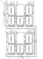
- FIG. 9 is a configuration diagram showing a third example of the BMS 1 according to the embodiment.
- the third example attention is paid to six battery packs 10 among the plurality of battery packs 10, and one or more battery cells constituting the assembled battery include a plurality of batteries constituting one battery pack 10 in the assembled battery.
- Six sets of cells 11 are shown in FIG.
- the CMUs 104 to 109 are shown as the monitoring circuit 100
- the BMU 203 is shown as the management circuit 200.
- a motor 400 is shown as a load to which power is supplied from the assembled battery, and a power line 405 (bus bar) connecting the assembled battery and the motor 400 is shown.
- the CMUs 104 to 109 are examples of a plurality of cell monitoring circuits that monitor one or more battery cells that constitute a battery pack. Although six cell monitoring circuits (CMUs 104 to 109) are shown here as a plurality of cell monitoring circuits, the number of cell monitoring circuits is not particularly limited as long as it is two or more.
- the CMUs 104 to 109 monitor the voltage of each of the plurality of battery cells 11.
- an example is shown in which each of the CMUs 104 to 109 monitors different battery cells 11 (specifically, battery cells 11 included in different battery packs 10), but each of the CMUs 104 to 109 monitors the same battery cell 11. (Specifically, battery cells 11 included in the same battery pack 10) may be monitored.
- Each of the plurality of cell monitoring circuits is connected to other cell monitoring circuits through wired communication.
- CMU 104 is connected to CMU 105 through wired communication
- CMU 105 is connected to CMUs 104 and 106 through wired communication
- CMU 106 is connected to CMU 105 through wired communication
- CMU 107 is connected to CMU 108 through wired communication.
- the CMU 108 is connected to the CMUs 107 and 109 by wired communication
- the CMU 109 is connected to the CMU 108 by wired communication.
- the CMU 104 includes a wireless communication circuit 111 and a communication antenna ANT7 for communicating with the BMU 203
- the CMU 106 includes a wireless communication circuit 111 and a communication antenna ANT8 for communicating with the BMU 203
- CMU107 includes a wireless communication circuit 111 and communication antenna ANT9 for communicating with BMU203
- CMU109 includes a wireless communication circuit 111 and communication antenna ANT10 for communicating with BMU203.
- the CMUs 104 to 109 include a voltage monitoring circuit 112.
- the CMUs 104, 106, 107, and 109 each include a battery 12. Even when the wireless communication circuit 111 is not receiving power from the voltage monitoring circuit 112, specific functions included in the wireless communication circuit 111 can be operated by the battery 12.
- the functions of the wireless communication circuit 111 and the voltage monitoring circuit 112 of the CMU 104 will be explained in the description of the wireless communication circuit 111 and the voltage monitoring circuit 112 of the first example. It will be replaced.
- the identification information of the wireless communication circuit 111 of the CMU 104 is assumed to be "ID11".
- the functions of the wireless communication circuit 111 and the voltage monitoring circuit 112 of the CMU 106 will be explained in the description of the wireless communication circuit 111 and the voltage monitoring circuit 112 of the first example. It will be replaced.
- the identification information of the wireless communication circuit 111 of the CMU 106 is assumed to be "ID12".
- the CMU 105 is not equipped with a wireless communication circuit and a communication antenna, it is connected to the CMUs 104 and 106 by wired communication. It is possible to communicate with the BMU 203 using ANT8.
- the description of the function of the voltage monitoring circuit 112 of the CMU 105 is basically the same as the description of the voltage monitoring circuit 112 of the first example except that the CMU 101 is replaced with the CMU 105 and the BMU 201 is replaced with the BMU 203.
- the functions of the wireless communication circuit 111 and the voltage monitoring circuit 112 of the CMU 107 will be explained in the description of the wireless communication circuit 111 and the voltage monitoring circuit 112 of the first example. It will be replaced.
- the identification information of the wireless communication circuit 111 of the CMU 107 is assumed to be "ID21".
- the functions of the wireless communication circuit 111 and the voltage monitoring circuit 112 of the CMU 109 will be explained in the description of the wireless communication circuit 111 and the voltage monitoring circuit 112 of the first example. It will be replaced.
- the identification information of the wireless communication circuit 111 of the CMU 109 is assumed to be "ID22".
- the CMU 108 is not equipped with a wireless communication circuit and a communication antenna, but is connected to the CMUs 107 and 109 by wired communication. ANT10 can be used to communicate with BMU203.
- the description of the function of the voltage monitoring circuit 112 of the CMU 108 is basically the same as the description of the voltage monitoring circuit 112 of the first example except that the CMU 101 is replaced with the CMU 108 and the BMU 201 is replaced with the BMU 203.
- the BMU 203 includes a communication antenna ANT11. Although illustration of the functional blocks of the BMU 203 is omitted, the BMU 203 includes the wireless communication circuit 211 and the MCU 213 as described in the first example. A wireless communication circuit 211 of the BMU 203 communicates with the CMUs 104 to 109 via a communication antenna ANT11.
- the BMS 1 of the third example operates as follows.
- the BMU 203 When the BMU 203 acquires the status (for example, voltage value) of the plurality of battery cells 11 monitored by the CMU assigned the identification information "ID11", the BMU 203 transmits the monitoring results to the CMU assigned the identification information "ID11".
- a request signal is sent by broadcast.
- the CMU 104 receives the request signal, and since the request signal includes identification information that matches its own identification information "ID11", the CMU 104 determines that the request signal is addressed to itself, and sends the request signal to the plurality of devices that it monitors. Processing for transmitting the monitoring results of the battery cells 11 to the BMU 203 is performed. Further, for example, when there is no abnormality in the wireless communication between the CMU 104 and the BMU 203, it is assumed that the CMU 105 is set to communicate with the BMU 203 using the wireless communication circuit 111 of the CMU 104 and the communication antenna ANT7.
- the CMU 104 causes the CMU 105 connected to the CMU 104 through wired communication to perform processing for transmitting the monitoring results of the plurality of battery cells 11 monitored by the CMU 105 to the CMU 104.
- the CMUs 104 and 105 acquire the respective voltage values of the plurality of battery cells 11 by the multiplexer 143, and the CMU 104 acquires each voltage value and the position of each voltage value among the plurality of battery cells 11.
- Information indicating whether it is the voltage value of the battery cell 11 and identification information of the CMU 104 are transmitted to the BMU 203 .
- the BMU 203 receives from the CMU 104 information indicating the voltage values of the plurality of battery cells 11 monitored by the CMUs 104 and 105 and identification information of the CMU 104 as a response to the request signal.
- the CMU 106 since the CMU 106 is connected to the CMU 104 through wired communication via the CMU 105, if there is an abnormality in the wireless communication between the CMU 106 and the BMU 203, the CMU 104 will also transmit the monitoring results of the plurality of battery cells 11 monitored by the CMU 106 to the BMU 203. can be sent to.
- the BMU 203 when acquiring the status (for example, voltage value) of a plurality of battery cells 11 monitored by a CMU to which identification information "ID12" is assigned, the BMU 203 transmits the monitoring results to the CMU to which identification information "ID12" is assigned. A request signal to be sent to is transmitted by broadcast.
- the CMU 106 receives the request signal, and since the request signal includes identification information that matches its own identification information "ID12", the CMU 106 determines that the request signal is addressed to itself, and sends the request signal to the plurality of devices that it monitors. Processing for transmitting the monitoring results of the battery cells 11 to the BMU 203 is performed. Specifically, the CMU 106 acquires each voltage value of the plurality of battery cells 11 using the multiplexer 143, and the CMU 106 determines each voltage value and the position of the battery cell among the plurality of battery cells 11 at which each voltage value is located. 11 and identification information of the CMU 106 are transmitted to the BMU 203.
- the BMU 203 receives from the CMU 106 information indicating the voltage values of the plurality of battery cells 11 monitored by the CMU 106 and identification information of the CMU 106 as a response to the request signal.
- the CMU 104 since the CMU 104 is connected to the CMU 106 through wired communication via the CMU 105, if there is an abnormality in the wireless communication between the CMU 104 and the BMU 203, the CMU 106 displays the monitoring results of the plurality of battery cells 11 monitored by the CMU 104 and 105. can also be transmitted to the BMU 203.
- Communication of the monitoring results of the CMUs 107 to 109 can be performed in the same manner as that of the CMUs 104 to 107, so a description thereof will be omitted.
- each of the plurality of cell monitoring circuits (for example, CMUs 104 to 109) is connected to other cell monitoring circuits through wired communication, cells that are not equipped with a wireless communication circuit and a communication antenna
- the monitoring circuits (for example, CMUs 105 and 108) can also communicate with the BMU 203 through wireless communication circuits 111 and communication antennas included in other cell monitoring circuits connected by wired communication.
- at least two cell monitoring circuits (for example, CMUs 104 and 106) can communicate with BMU 203 via wireless communication circuit 111 and communication antenna, communication between one of CMUs 104 and 106 and BMU 203 is possible.
- FIG. 10 is a configuration diagram showing a fourth example of the BMS 1 according to the embodiment.
- FIG. 11 is a configuration diagram showing a fifth example of the BMS 1 according to the embodiment.
- the BMS 1 of the fourth and fifth examples differs from the BMS 1 of the third example in that each of the plurality of cell monitoring circuits (CMUs 104 to 109) and other cell monitoring circuits are insulated by an insulating section.
- the other points are the same as the BMS1 of the third example, so the explanation will be omitted.
- a transformer 503 is shown as an insulator, and transformers 503 are provided between CMU104 and CMU105, between CMU105 and CMU106, between CMU107 and CMU108, and between CMU108 and CMU109. It is being
- a capacitor 504 is shown as an insulating part, and the capacitor 504 is provided between CMU104 and CMU105, between CMU105 and CMU106, between CMU107 and CMU108, and between CMU108 and CMU109. It is being
- the magnitude of the voltage applied to each of the CMUs 104 to 109 differs depending on the battery cell to be monitored. Therefore, by insulating the CMUs, ESD (Electro Static Discharge) resistance can be increased and power consumption can be reduced.
- ESD Electro Static Discharge
- the BMS 1 may include a plurality of cell monitoring circuits including CMUs 101 and 102, and each of the plurality of cell monitoring circuits is connected to other cell monitoring circuits through wired communication. Good too. That is, wired communication may be performed between a plurality of cell monitoring circuits.
- each of the plurality of cell monitoring circuits and the other cell monitoring circuits may be insulated by an insulating section.
- two current monitoring circuits may be provided, and a wireless communication circuit and a communication circuit for each of the two current monitoring circuits to communicate with the management circuit 200. It may also be equipped with an antenna.
- each component included in the BMS 1 may be configured with dedicated hardware, or may be realized by executing a software program suitable for each component.
- Each component may be realized by a program execution unit such as a CPU or a processor reading and executing a software program recorded on a recording medium such as a hard disk or a semiconductor memory.
- a part or all of the functions of the BMS 1 according to the above embodiment are typically realized as an LSI, which is an integrated circuit. These may be integrated into one chip individually, or may be integrated into one chip including some or all of them. Further, circuit integration is not limited to LSI, and may be realized using a dedicated circuit or a general-purpose processor.
- An FPGA Field Programmable Gate Array
- a reconfigurable processor that can reconfigure the connections and settings of circuit cells inside the LSI may be used.
- a battery management system for managing an assembled battery comprising: a management circuit that manages the assembled battery; a first cell monitoring circuit that monitors one or more battery cells forming the assembled battery; a second cell monitoring circuit that monitors the one or more battery cells monitored by the first cell monitoring circuit; the first cell monitoring circuit includes a wireless communication circuit for communicating with the management circuit; and a communication antenna, and the second cell monitoring circuit includes a power line communication circuit using a power line in the assembled battery for communicating with the management circuit.
- the first cell monitoring circuit and the second cell monitoring circuit each monitor the same battery cell, and regarding information regarding the battery cell, the first cell monitoring circuit monitors the wireless communication circuit and the communication antenna.
- the second cell monitoring circuit can communicate with the management circuit via the power line communication circuit.
- information regarding battery cells even if there is an abnormality in wireless communication between the first cell monitoring circuit and the management circuit, power line communication can be performed between the second cell monitoring circuit and the management circuit. can.
- information regarding battery cells even if there is an abnormality in the power line communication between the second cell monitoring circuit and the management circuit, it is possible to perform wireless communication between the first cell monitoring circuit and the management circuit. can. Therefore, communication redundancy within the battery management system can be increased.
- a wire harness is required for wired communication, and as the number of wired communications increases, the number of wire harnesses increases, so all communications between the management circuit, the first cell monitoring circuit, and the second cell monitoring circuit are wired. In this case, the system becomes large.
- the communication between the management circuit and the first cell monitoring circuit is wireless communication, an increase in the number of wire harnesses can be suppressed.
- wired communication may be performed between multiple cell monitoring circuits.
- a battery management system for managing an assembled battery comprising a management circuit for managing the assembled battery, and a plurality of cell monitoring circuits for monitoring one or more battery cells constituting the assembled battery, Each of the plurality of cell monitoring circuits is connected to another cell monitoring circuit by wired communication, and at least two of the plurality of cell monitoring circuits are connected to each other by wireless communication for communicating with the management circuit.
- Battery management system with circuitry and communication antenna.
- each of the plurality of cell monitoring circuits is connected to other cell monitoring circuits through wired communication
- cell monitoring circuits that are not equipped with a wireless communication circuit or communication antenna can also be connected to other cell monitoring circuits through wired communication.
- a wireless communication circuit and a communication antenna included in the cell monitoring circuit can communicate with the management circuit.
- at least two cell monitoring circuits can communicate with the management circuit via the wireless communication circuit and the communication antenna, the communication between the cell monitoring circuit of one of the at least two cell monitoring circuits and the management circuit is possible. Even if there is an abnormality in the wireless communication of the cell monitoring circuit, wireless communication can be performed between the management circuit and any other cell monitoring circuit of the at least two cell monitoring circuits. Therefore, communication redundancy within the battery management system can be increased.
- the plurality of cell monitoring circuits need to include a wireless communication circuit and a communication antenna, wireless communication between the management circuit and the plurality of cell monitoring circuits can be realized at low cost.
- the magnitude of the voltage applied to each of the plurality of cell monitoring circuits differs depending on the battery cell to be monitored. Therefore, by insulating the cell monitoring circuits, ESD resistance can be increased and power consumption can be reduced.
- a first current monitoring circuit and a second current monitoring circuit are provided for measuring the current flowing through the assembled battery, and the first current monitoring circuit and the second current monitoring circuit are each configured to measure the current flowing through the assembled battery.
- the battery management system according to any one of techniques 1 to 4, comprising a wireless communication circuit and a communication antenna for communicating with a management circuit.
- two current monitoring circuits are provided, and each can wirelessly communicate with the management circuit, so it is possible to increase the redundancy of communication regarding the current monitoring results within the battery management system.
- the present disclosure can be applied to a battery management system where wireless communication is performed within the system.
Landscapes
- Engineering & Computer Science (AREA)
- Chemical & Material Sciences (AREA)
- Chemical Kinetics & Catalysis (AREA)
- Electrochemistry (AREA)
- General Chemical & Material Sciences (AREA)
- Power Engineering (AREA)
- Physics & Mathematics (AREA)
- General Physics & Mathematics (AREA)
- Manufacturing & Machinery (AREA)
- Computer Networks & Wireless Communication (AREA)
- Signal Processing (AREA)
- Microelectronics & Electronic Packaging (AREA)
- Aviation & Aerospace Engineering (AREA)
- Computer Vision & Pattern Recognition (AREA)
- Theoretical Computer Science (AREA)
- Secondary Cells (AREA)
- Charge And Discharge Circuits For Batteries Or The Like (AREA)
- Battery Mounting, Suspending (AREA)
- Radar Systems Or Details Thereof (AREA)
- Mobile Radio Communication Systems (AREA)
Abstract
BMS(1)は、組電池を管理するBMU(201)と、組電池を構成する1以上の電池セル(11)を監視する第一のCMU(101)と、第一のCMU(101)が監視する1以上の電池セル(11)を監視する第二のセルCMU(102)と、を備え、第一のCMU(101)は、BMU(201)と通信するための無線通信回路(111)および通信アンテナ(ANT1)を備え、第二のセル監視回路CMU(102)は、BMU(201)と通信するための、組電池における電力線(405)を使用した電力線通信回路(113)を備える。
Description
本開示は、組電池を管理するためのバッテリマネジメントシステムに関する。
特許文献1には、組電池を構成する複数の電池セルを管理するための技術が開示されている。
特許文献1に開示されるようなバッテリマネジメントシステム内では、組電池を管理する管理回路と組電池を監視する複数の監視回路との間で通信が行われる。しかしながら、通信線の断線、外部からのノイズ、または、管理回路と複数の監視回路のそれぞれとの間の通信の相互作用などによって、通信が失敗するおそれがある。
そこで、本開示は、バッテリマネジメントシステム内の通信の冗長性を高めることができるバッテリマネジメントシステムを提供する。
本開示に係るバッテリマネジメントシステムは、組電池を管理するためのバッテリマネジメントシステムであって、前記組電池を管理する管理回路と、前記組電池を構成する1以上の電池セルを監視する第一のセル監視回路と、前記第一のセル監視回路が監視する前記1以上の電池セルを監視する第二のセル監視回路と、を備え、前記第一のセル監視回路は、前記管理回路と通信するための無線通信回路および通信アンテナを備え、前記第二のセル監視回路は、前記管理回路と通信するための、前記組電池における電力線を使用した電力線通信回路を備える。
本開示に係るバッテリマネジメントシステムは、組電池を管理するためのバッテリマネジメントシステムであって、前記組電池を管理する管理回路と、前記組電池を構成する1以上の電池セルを監視する複数のセル監視回路を備え、前記複数のセル監視回路のそれぞれは、有線通信により、他のセル監視回路と接続され、前記複数のセル監視回路のうちの少なくとも2つのセル監視回路は、前記管理回路と通信するための無線通信回路および通信アンテナを備える。
なお、これらの包括的または具体的な態様は、システム、方法、集積回路、コンピュータプログラムまたはコンピュータ読み取り可能なCD-ROMなどの記録媒体で実現されてもよく、システム、方法、集積回路、コンピュータプログラムおよび記録媒体の任意な組み合わせで実現されてもよい。
本開示の一態様に係るバッテリマネジメントシステムによれば、バッテリマネジメントシステム内の通信の冗長性を高めることができる。
以下、実施の形態について、図面を参照しながら具体的に説明する。
なお、以下で説明する実施の形態は、いずれも包括的または具体的な例を示すものである。以下の実施の形態で示される数値、形状、材料、構成要素、構成要素の配置位置および接続形態などは、一例であり、本開示を限定する主旨ではない。
(実施の形態)
以下、実施の形態に係るバッテリマネジメントシステムについて説明する。
以下、実施の形態に係るバッテリマネジメントシステムについて説明する。
図1は、実施の形態に係るバッテリマネジメントシステム1(以下BMS(Battery Management System)1とも記載する)の一例を示す外観図である。
BMS1は、組電池を管理するためのシステムである。例えば、BMS1は、組電池のSOC(State Of Charge)、SOH(State Of Health)およびSOP(State Of Power)などを管理する。また、BMS1は、組電池の異常を監視する。BMS1は、組電池を管理する管理回路200と、組電池を監視する複数の監視回路100とを備える。例えば、組電池は、複数の電池パック10が直列または並列に接続されることで構成されている。また、電池パック10は、1以上の電池セルによって構成される。電池パック10が複数の電池セルによって構成される場合、複数の電池セルは直列に接続される。
例えば、監視回路100は、複数の電池パック10のそれぞれの上に配置される。監視回路100の具体例であるCMU(Cell Monitoring Unit)101~109およびCMU(Current Monitoring Unit)301~303については後述する。
例えば、管理回路200は、接続箱20を介して組電池と接続される。管理回路200の具体例であるBMU(Battery Management Unit)201~203については後述する。
以下、実施の形態に係るBMS1の具体例として、第1例から第5例を説明する。
[第1例]
まず、第1例について、図2から図6Cを用いて説明する。
まず、第1例について、図2から図6Cを用いて説明する。
図2は、実施の形態に係るBMS1の第1例を示す構成図である。
図3Aは、第一のセル監視回路(CMU101)が備える無線通信回路111の一例を示す構成図である。なお、図3Aには、図2の構成図における無線通信回路111の周辺部分も示されている。
図3Bは、第一のセル監視回路(CMU101)が備える電圧監視回路112の一例を示す構成図である。なお、図3Bには、図2の構成図における電圧監視回路112の周辺部分も示されている。
図4Aは、第二のセル監視回路(CMU102)が備える電力線通信回路113の一例を示す構成図である。なお、図4Aには、図2の構成図における電力線通信回路113の周辺部分も示されている。
図4Bは、第二のセル監視回路(CMU102)が備える電圧監視回路114の一例を示す構成図である。なお、図4Bには、図2の構成図における電圧監視回路114の周辺部分も示されている。
図5は、電流監視回路(CMU301)が備える電流測定回路311の一例を示す構成図である。なお、図5には、図2の構成図における電流測定回路311の周辺部分も示されている。
図6Aは、管理回路(BMU201)が備える無線通信回路211の一例を示す構成図である。なお、図6Aには、図2の構成図における無線通信回路211の周辺部分も示されている。
図6Bは、管理回路(BMU201)が備える電力線通信回路212の一例を示す構成図である。なお、図6Bには、図2の構成図における電力線通信回路212の周辺部分も示されている。
図6Cは、管理回路(BMU201)が備えるMCU213の一例を示す構成図である。なお、図6Cには、図2の構成図におけるMCU213の周辺部分も示されている。
第1例では、複数の電池パック10のうちの1つの電池パック10に着目しており、組電池を構成する1以上の電池セルとして、組電池における1つの電池パック10を構成する複数の電池セル11が図2に示されている。また、監視回路100として、CMU101および102ならびにCMU301が示され、管理回路200として、BMU201が示されている。また、組電池からの電力が供給される負荷として、モータ400が示され、組電池とモータ400とを接続する電力線405(バスバー)、電力線405に挿入されたリレー401およびシャント抵抗402が示されている。
リレー401は、電力線405に流れる電流を遮断するためのスイッチである。例えば、リレー401は、CMU301で監視されている電流が異常と判定された場合にオフされて、電力線405に流れる電流を遮断する。また、例えば、リレー401は、CMU101または102で監視されている電圧が異常と判定された場合にオフされて、電力線405に流れる電流を遮断する。
シャント抵抗402は、電力線405に流れる電流を測定するための抵抗である。
CMU101は、組電池を構成する1以上の電池セルを監視する第一のセル監視回路の一例である。例えば、CMU101は、複数の電池セル11のそれぞれの電圧を監視する。CMU102は、第一のセル監視回路が監視する1以上の電池セルを監視する第二のセル監視回路の一例である。例えば、CMU102は、CMU101が監視する複数の電池セル11のそれぞれの電圧を監視する。CMU101とCMU102とは、それぞれ同じ電池セル11を監視する。
図2に示されるように、CMU101は、BMU201と通信するための無線通信回路111および通信アンテナANT1を備える。また、CMU101は、複数の電池セル11のそれぞれの電圧を監視する電圧監視回路112を備える。例えば、無線通信回路111と電圧監視回路112とは、それぞれ異なるIC(Integrated Circuit)によって実現される。なお、無線通信回路111および電圧監視回路112は、1つのICによって実現されてもよい。
図3Aに示されるように、無線通信回路111は、電圧変換回路(Reg.)121、タイマ回路(Timer)122、通信インタフェース(Com.I/F)123、クロック生成回路(Clock gen)124、位相同期回路(PLL)125、変調回路(Modulator)126、送信回路(Tx)127、復調回路(Demodulator)128、受信回路(Rx)129、不揮発性メモリ(NVM)130、通信エラー判定回路(RF Error)131および起動回路(Wake up)132を備える。
電圧変換回路121は、電圧監視回路112から入力された電圧を、無線通信回路111を動作させるための電圧に変換して出力する回路である。
タイマ回路122は、時間をカウントする回路である。例えば、タイマ回路122は、無線通信回路111を間欠動作させるために用いられる。
通信インタフェース123は、無線通信回路111と電圧監視回路112との通信を行うためのインタフェースである。なお、無線通信回路111および電圧監視回路112が、1つのICによって実現される場合には、通信インタフェース123は、設けられていなくてもよい。
クロック生成回路124は、CMU101におけるクロックを生成するための回路である。
位相同期回路125は、受信信号の位相と一致するようにローカル信号の位相を調整する回路である。
変調回路126は、BMU201へ送信される信号を変調する回路である。
送信回路127は、BMU201へ信号を送信するための回路である。送信回路127は、通信アンテナANT1を介してBMU201へ信号を送信する。
復調回路128は、BMU201から受信した信号を復調する回路である。
受信回路129は、BMU201から信号を受信するための回路である。受信回路129は、通信アンテナANT1を介してBMU201から信号を受信する。
不揮発性メモリ130は、無線通信回路111の識別情報を記憶する。例えば、不揮発性メモリ130は、識別情報「ID2A」を記憶する。なお、図3Aでは、不揮発性メモリ130を示しているが、識別情報は、無線通信回路111が備える任意のメモリに記憶されていればよい。後述する電力線通信回路および無線通信回路については、識別情報が記憶されるメモリの図示を省略している。
通信エラー判定回路131は、CMU101とBMU201との間の通信に異常が生じているか否かを判定する回路である。
起動回路132は、無線通信回路111を起動させるための回路である。
また、図2に示されるように、例えば、CMU101は、LED133を備えていてもよい。LED133は、例えば、無線通信回路111が特定の条件を満たしたときに発光する。
図3Bに示されるように、電圧監視回路112は、電圧変換回路(Reg.)141、タイマ回路(Timer)142、マルチプレクサ(MUX)143、ADコンバータ(ADC)144、通信インタフェース(Com.I/F)145、位相同期回路(PLL)146、暗号回路(Encryption)147およびスイッチ148を備える。
電圧変換回路141は、組電池から入力された電圧を、電圧監視回路112を動作させるための電圧に変換して出力する回路である。
タイマ回路142は、時間をカウントする回路である。例えば、タイマ回路142は、無線通信回路111を間欠動作させるための回路である。なお、CMU101は、無線通信回路111および電圧監視回路112にタイマ回路122および142を備えているが、タイマ回路122および142の両方を備えていなくてもよい。つまり、無線通信回路111はタイマ回路122を備えていなくてもよい、あるいは、電圧監視回路112はタイマ回路142を備えていなくてもよい。
マルチプレクサ143は、複数の電池セル11のうちから1つの電池セル11を選択して、選択した電池セル11の両端の電圧を出力する。つまり、マルチプレクサ143は、複数の電池セル11のそれぞれの電圧を出力することができる。
ADコンバータ144は、マルチプレクサ143で選択された電池セル11の電圧値(アナログ値)をデジタル値に変換する。
通信インタフェース145は、無線通信回路111と電圧監視回路112との通信を行うためのインタフェースである。なお、無線通信回路111および電圧監視回路112が、1つのICによって実現される場合には、通信インタフェース145は、設けられていなくてもよい。
位相同期回路146は、受信信号の位相と一致するようにローカル信号の位相を調整する回路である。
暗号回路147は、信号の暗号化および復号を行う回路である。例えば、暗号回路147は、無線通信回路111ひいてはBMU201へ送信される信号を、暗号化鍵(Key)を用いて暗号化する。
スイッチ148は、無線通信回路111への電力の供給のオンおよびオフを切り替えるスイッチであり、例えばトランジスタなどである。スイッチ148は、起動回路132からの制御信号によって制御される。起動回路132は、スイッチ148を制御して、無線通信回路111へ電力の供給を制御することで、無線通信回路111の起動を制御することができる。
CMU101は、電圧監視回路112によって、複数の電池セル11のそれぞれの電圧値を検知し、検知した電圧値を無線通信回路111によってBMU201へ送信する。
図2に示されるように、CMU102は、BMU201と通信するための、組電池における電力線405(例えばバスバー)を使用した電力線通信回路113を備える。また、CMU102は、複数の電池セル11のそれぞれの電圧を監視する電圧監視回路114を備える。例えば、電力線通信回路113と電圧監視回路114とは、それぞれ異なるICによって実現される。なお、電力線通信回路113および電圧監視回路114は、1つのICによって実現されてもよい。
図2および図4Aに示されるように、電力線通信回路113は、電圧変換回路(Reg.)121、タイマ回路(Timer)122、通信インタフェース(Com.I/F)123、クロック生成回路(Clock gen)124、位相同期回路(PLL)125、変調回路(Modulator)126、復調回路(Demodulator)128、通信エラー判定回路(RF Error)131、起動回路(Wake up)132、増幅回路134および135、コンデンサ136および137ならびにコイル138を備える。また、図4Aには、電力線通信回路113の識別情報として「ID2B」が示されている。
電力線通信回路113が備える、電圧変換回路121、タイマ回路122、通信インタフェース123、クロック生成回路124、位相同期回路125、変調回路126、復調回路128、通信エラー判定回路131および起動回路132の機能の説明は、上述した無線通信回路111が備えるものの説明において、無線通信回路111を電力線通信回路113、電圧監視回路112を電圧監視回路114、CMU101をCMU102に置き換えたものとなる。
増幅回路134は、BMU201へ送信される信号を増幅する回路である。
増幅回路135は、BMU201から受信した信号を増幅する回路である。
コンデンサ136および137は、BMU201から電力線通信によって受信した信号に重畳した直流成分を遮断する。
コイル138は、CMU102からBMU201へ送信される信号を電力線に重畳させ、また、BMU201からCMU102へ送信される信号であって、電力線に重畳された信号を抽出する。
また、図2に示されるように、例えば、CMU102は、LED133を備えていてもよい。LED133は、例えば、電力線通信回路113が特定の条件を満たしたときに発光する。
図4Bに示されるように、電圧監視回路114は、電圧変換回路(Reg.)141、タイマ回路(Timer)142、通信インタフェース(Com.I/F)145、暗号回路(Encryption)147、スイッチ148およびコンパレータ149~152を備える。
電圧監視回路114が備える、電圧変換回路141、タイマ回路142、通信インタフェース145、暗号回路147およびスイッチ148の機能の説明は、上述した電圧監視回路112が備えるものの説明において、無線通信回路111を電力線通信回路113、電圧監視回路112を電圧監視回路114、CMU101をCMU102に置き換えたものとなる。
コンパレータ149~152のそれぞれは、複数の電池セル11のそれぞれに対して一対一で設けられる。ここでは、一例として4つのコンパレータ149~152が示されているが、コンパレータの数は、電池セル11の数に対応した数となる。例えば、複数の電池セル11として4つの電池セル11が直列に接続されている場合、コンパレータ149は、1つ目の電池セル11の電圧と所定の電圧とを比較し、コンパレータ150は、2つ目の電池セル11の電圧と所定の電圧とを比較し、コンパレータ151は、3つ目の電池セル11の電圧と所定の電圧とを比較し、コンパレータ152は、4つ目の電池セル11の電圧と所定の電圧とを比較する。このように、複数の電池セル11のそれぞれに対して一対一でコンパレータが設けられることで、電圧監視回路114は、複数の電池セル11のそれぞれが所定の電圧以上であるか(例えば過電圧であるか)、または、複数の電池セル11のそれぞれが所定の電圧以下であるか(例えば電圧が低すぎるか)を判定することができる。つまり、電圧監視回路114は、複数の電池セル11のそれぞれの電圧が異常であるか否かを判定することができる。
CMU102は、電圧監視回路114によって、複数の電池セル11のそれぞれの電圧が異常であるか否かを判定し、電力線通信回路113によって、判定結果をBMU201へ送信する。
なお、CMU102は、電圧監視回路114の代わりに電圧監視回路112を備えていてもよい。つまり、CMU102は、複数の電池セル11のそれぞれの電圧値を検知し、検知した電圧値をBMU201へ送信してもよい。また、CMU101は、電圧監視回路112の代わりに電圧監視回路114を備えていてもよい。つまり、CMU101は、複数の電池セル11のそれぞれの電圧の異常が異常であるか否かを判定し、判定結果をBMU201へ送信してもよい。
図2に示されるように、CMU301は、組電池に流れる電流を監視する電流測定回路311を備える。また、CMU301は、電源回路312および絶縁通信回路313を備える。
電源回路312は、CMU301に電力を供給するための回路であり、BMU201から供給された電力をCMU301に供給する。例えば、電源回路312は、トランス501を介してBMU201から電力が供給される。
絶縁通信回路313は、CMU301とBMU201とを絶縁した状態で、CMU301とBMU201との通信を行うための回路である。例えば、絶縁通信回路313は、トランス502を用いることで、CMU301とBMU201とを絶縁した状態で、CMU301とBMU201との通信を行うことができる。
電流測定回路311は、組電池に流れる電流を測定する回路である。具体的には、電流測定回路311は、電力線405に設けられたシャント抵抗402に電流が流れることで発生する電圧を測定することで、電力線405に流れる電流、すなわち、組電池に流れる電流を測定する。図5に示されるように、電流測定回路311は、増幅回路321、ADコンバータ(ADC)322および通信インタフェース(Com.I/F)323を備える。
増幅回路321は、シャント抵抗402に発生する電圧を増幅する。シャント抵抗402の抵抗値は非常に小さく、シャント抵抗402に発生する電圧も小さくなるため、増幅回路321が設けられる。
ADコンバータ322は、シャント抵抗402に発生する電圧の値(アナログ値)をデジタル値に変換する。
通信インタフェース323は、CMU301とBMU201との通信を行うためのインタフェースである。
図2に示されるように、BMU201は、CMU101と通信するための無線通信回路211および通信アンテナANT2、ならびに、CMU102と通信するための電力線通信回路212を備える。また、BMU201は、組電池を管理するためのMCU(Micro Controller Unit)213を備える。なお、無線通信回路211、電力線通信回路212およびMCU213は、1つのIC(例えば1つのMCU)によって実現されてもよい。また、BMU201は、電源回路215および絶縁通信回路216を備える。
電源回路215は、CMU301に電力を供給するための回路である。例えば、電源回路215は、トランス501を介してCMU301に電力を供給する。
絶縁通信回路216は、CMU301とBMU201とを絶縁した状態で、CMU301とBMU201との通信を行うための回路である。例えば、絶縁通信回路216は、トランス502を用いることで、CMU301とBMU201とを絶縁した状態で、CMU301とBMU201との通信を行うことができる。
CMU301は、数100Vと大きな電圧の組電池に流れる電流を監視しており、大きな電圧を取り扱っているのに対して、BMU201は、数V程度の電圧を取り扱っているため、CMU301とBMU201とは、トランス501および502を介して接続されることで絶縁されている。
図6Aに示されるように、無線通信回路211は、電圧変換回路(Reg.)221、タイマ回路(Timer)222、通信インタフェース(Com.I/F)223、クロック生成回路(Clock gen)224、位相同期回路(PLL)225、変調回路(Modulator)226、送信回路(Tx)227、復調回路(Demodulator)228、受信回路(Rx)229、通信エラー判定回路(RF Error)231および起動回路(Wake up)232を備える。また、図6Aには、無線通信回路211の識別情報として「ID0A」が示されている。
電圧変換回路221は、任意の電源から入力された電圧を、無線通信回路211を動作させるための電圧に変換して出力する回路である。
タイマ回路222は、時間をカウントする回路である。
通信インタフェース223は、無線通信回路211とMCU213との通信を行うためのインタフェースである。なお、無線通信回路211およびMCU213が、1つのICによって実現される場合には、通信インタフェース223は、設けられていなくてもよい。
クロック生成回路224は、BMU201におけるクロックを生成するための回路である。
位相同期回路225は、受信信号の位相と一致するようにローカル信号の位相を調整する回路である。
変調回路226は、CMU101へ送信される信号を変調する回路である。
送信回路227は、CMU101へ信号を送信するための回路である。送信回路227は、通信アンテナANT2を介してCMU101へ信号を送信する。
復調回路228は、CMU101から受信した信号を復調する回路である。
受信回路229は、CMU101から信号を受信するための回路である。受信回路229は、通信アンテナANT2を介してCMU101から信号を受信する。
通信エラー判定回路231は、CMU101とBMU201との間の通信に異常が生じているか否かを判定する回路である。
起動回路232は、MCU213を起動させるための回路である。
図2および図6Bに示されるように、電力線通信回路212は、電圧変換回路(Reg.)221、タイマ回路(Timer)222、通信インタフェース(Com.I/F)223、クロック生成回路(Clock gen)224、位相同期回路(PLL)225、変調回路(Modulator)226、復調回路(Demodulator)228、通信エラー判定回路(RF Error)231、起動回路(Wake up)232、増幅回路234および235、コンデンサ236および237ならびにコイル238を備える。また、図6Bには、電力線通信回路212の識別情報として「ID0B」が示されている。
電力線通信回路212が備える、電圧変換回路221、タイマ回路222、通信インタフェース223、クロック生成回路224、位相同期回路225、変調回路226、復調回路228、通信エラー判定回路231および起動回路232の機能の説明は、上述した無線通信回路211が備えるものの説明において、無線通信回路211を電力線通信回路212、CMU101をCMU102に置き換えたものとなる。
増幅回路234は、CMU102へ送信される信号を増幅する回路である。
増幅回路235は、CMU102から受信した信号を増幅する回路である。
コンデンサ236および237は、CMU102から電力線通信によって受信した信号に重畳した直流成分を遮断する。
コイル238は、BMU201からCMU102へ送信される信号を電力線に重畳させ、また、BMU201からCMU102へ送信される信号であって、電力線に重畳された信号を抽出する。
図6Cに示されるように、MCU213は、暗号回路(Encryption)241、識別回路(ID identification circuit)242、暗号回路(Encryption)243および識別回路(ID identification circuit)244を備える。MCU213は、CAN(Controller Area Network)に接続されており、MCU213とCANとの間にはファイアウォールが設けられている。また、MCU213には、電池パック10における複数の電池セル11のそれぞれの位置と各電池パック10のCMUの無線通信回路などの識別情報との対応関係を示すテーブル(Table of cell position and RF com. ID)245が記憶されている。
暗号回路241は、信号の暗号化および復号を行う回路である。例えば、暗号回路241は、CMU101から送信された信号(例えば電池セル11の電圧値)を、暗号化鍵(Key)を用いて復号する。
識別回路242は、テーブル245を用いて、CMU101から送信された信号に含まれる電池セル11の電圧値が、どの電池パック10におけるどの位置の電池セル11の電圧値であるかを識別する。
暗号回路243は、信号の暗号化および復号を行う回路である。例えば、CMU102から送信された信号(例えば電池セル11の電圧が異常であるか否かの判定結果)を、暗号化鍵(Key)を用いて復号する。
識別回路244は、テーブル245を用いて、CMU102から送信された信号に含まれる電池セル11の電圧の判定結果が、どの電池パック10におけるどの位置の電池セル11の電圧の判定結果であるかを識別する。
以上の回路構成によって、第1例のBMS1は、以下のように動作する。
BMU201は、識別情報「ID2A」が付与されたCMUが監視する複数の電池セル11の状態(例えば電圧値)を取得する場合、識別情報「ID2A」が付与されたCMUに監視結果をBMU201へ送信させる要求信号をブロードキャストにより送信する。
CMU101は、要求信号を受信し、自身の識別情報「ID2A」と一致する識別情報が要求信号に含まれているため、要求信号が自身宛ての信号であると判定し、自身が監視する複数の電池セル11の監視結果をBMU201へ送信するための処理を行う。具体的には、CMU101は、マルチプレクサ143によって複数の電池セル11のそれぞれの電圧値を取得し、各電圧値と、各電圧値が複数の電池セル11のうちのどの位置の電池セル11の電圧値であるかを示す情報と、CMU101の識別情報とをBMU201へ送信する。例えば、マルチプレクサ143が電圧値を取得した際にどの電池セル11を選択したかに応じて、当該電圧値が複数の電池セル11のうちのどの位置の電池セル11の電圧値であるかを特定することができる。
BMU201は、要求信号に対する応答として、CMU101が監視する複数の電池セル11の電圧値を示す情報およびCMU101の識別情報をCMU101から受信する。BMU201は、これらの情報をテーブル245に照合することで、複数の電池セル11の電圧値のそれぞれが、どの電池パック10におけるどの位置の電池セル11の電圧値であるかを識別することができる。
また、BMU201は、CMU102が監視する複数の電池セル11の状態(例えば電圧の異常の判定結果)を取得する場合、CMU102に監視結果をBMU201へ送信させる要求信号を送信する。
CMU102は、要求信号を受信し、自身が監視する複数の電池セル11の監視結果をBMU201へ送信するための処理を行う。具体的には、CMU102は、コンパレータ149~152によって複数の電池セル11のそれぞれの電圧が異常であるか否かを判定し、複数の電池セル11のそれぞれの電圧が異常の判定結果と、当該判定結果が複数の電池セル11のうちのどの位置の電池セル11の判定結果であるかを示す情報と、CMU102の識別情報とをBMU201へ送信する。例えば、どのコンパレータによって取得された電圧による判定結果であるかに応じて、当該判定結果が複数の電池セル11のうちのどの位置の電池セル11の電圧の異常の判定結果であるかを特定することができる。
BMU201は、要求信号に対する応答として、CMU102が監視する複数の電池セル11の電圧の異常の判定結果を示す情報およびCMU102の識別情報をCMU102から受信する。BMU201は、これらの情報をテーブル245に照合することで、複数の電池セル11の電圧の異常の判定結果のそれぞれが、どの電池パック10におけるどの位置の電池セル11の判定結果であるかを識別することができる。
また、BMU201は、CMU301が監視する組電池の状態(例えば組電池に流れる電流)を取得する場合、CMU301に監視結果をBMU201へ送信させる要求信号を送信する。
CMU301は、要求信号を受信し、自身が監視する組電池の監視結果をBMU201へ送信するための処理を行う。具体的には、CMU301は、組電池に流れる電流を計測し、BMU201へ送信する。これにより、BMU201は、組電池に流れる電流を取得することができる。
以上説明した通り、第1例では、CMU101および102は、それぞれ同じ電池セル11を監視しており、電池セル11に関する情報について、CMU101は、無線通信回路111および通信アンテナANT1を介してBMU201と通信可能となっており、CMU102は、電力線通信回路113を介してBMU201と通信可能となっている。つまり、電池セル11に関する情報について、CMU101とBMU201との間の無線通信に異常があった場合でも、CMU102とBMU201との間で電力線通信を行うことができる。また、電池セル11に関する情報について、CMU102とBMU201との間の電力線通信に異常があった場合でも、CMU101とBMU201との間で無線通信を行うことができる。したがって、BMS1内の通信の冗長性を高めることができる。
また、無線通信はノイズなどの影響を受けやすいため、BMU201と、CMU101および102との通信を全て無線通信とした場合、BMU201とCMU101との通信およびBMU201とCMU102との通信の両方が失敗してしまうおそれがある。一方で、有線通信はノイズなどの影響を受けにくいため、BMU201とCMU102との通信が有線の電力線通信であることで、BMU201とCMU101との通信およびBMU201とCMU102との通信の両方が失敗してしまうことを抑制できる。
また、有線通信にはワイヤハーネスが必要となり、有線通信が増えるとワイヤハーネスが増加するため、BMU201と、CMU101および102との通信を全て有線通信とした場合、システムが大型化してしまう。一方で、BMU201とCMU101との通信が無線通信であることで、ワイヤハーネスが増加することを抑制できる。
[第2例]
次に、第2例について、図7から図8Bを用いて説明する。
次に、第2例について、図7から図8Bを用いて説明する。
図7は、実施の形態に係るBMS1の第2例を示す構成図である。
図8Aは、第一の電流監視回路(CMU302)が備える電流測定回路314の一例を示す構成図である。なお、図8Aには、図7の構成図における電流測定回路314の周辺部分も示されている。
図8Bは、第一の電流監視回路(CMU302)が備える無線通信回路315の一例を示す構成図である。なお、図8Bには、図7の構成図における無線通信回路315の周辺部分も示されている。
第2例では、複数の電池パック10のうちの1つの電池パック10に着目しており、組電池を構成する1以上の電池セルとして、組電池における1つの電池パック10を構成する複数の電池セル11が図7に示されている。また、監視回路100として、CMU101および103ならびにCMU302および303が示され、管理回路200として、BMU202が示されている。また、組電池からの電力が供給される負荷として、モータ400が示され、組電池とモータ400とを接続する電力線405(バスバー)、電力線405に挿入されたリレー401ならびにシャント抵抗403および404が示されている。
リレー401は、電力線405に流れる電流を遮断するためのスイッチである。例えば、リレー401は、CMU302または303で監視されている電流が異常と判定された場合にオフされて、電力線405に流れる電流を遮断する。また、例えば、リレー401は、CMU101または103で監視されている電圧が異常と判定された場合にオフされて、電力線405に流れる電流を遮断する。
シャント抵抗403および404は、電力線405に流れる電流を測定するための抵抗である。
CMU101および103は、組電池を構成する1以上の電池セルを監視する複数のセル監視回路の一例である。ここでは、複数のセル監視回路として2つのセル監視回路(CMU101および103)が示されているが、セル監視回路の数は、図1に示されるように、3つ以上であってもよい。例えば、CMU101および103は、複数の電池セル11のそれぞれの電圧を監視する。ここでは、CMU101とCMU103とは、それぞれ同じ電池セル11(具体的には同じ電池パック10に含まれる電池セル11)を監視する例を示しているが、CMU101とCMU103とは、それぞれ異なる電池セル11(具体的には異なる電池パック10に含まれる電池セル11)を監視してもよい。
複数のセル監視回路のそれぞれは、有線通信により、他のセル監視回路と接続される。ここでは、図7に示されるように、CMU101は、有線通信によりCMU103と接続され、言い換えると、CMU103は、有線通信によりCMU101と接続される。
また、複数のセル監視回路のうちの少なくとも2つのセル監視回路は、管理回路200と通信するための無線通信回路および通信アンテナを備える。ここでは、図7に示されるように、CMU101は、BMU202と通信するための無線通信回路111および通信アンテナANT1を備え、CMU103は、BMU202と通信するための無線通信回路115および通信アンテナANT3を備える。また、CMU101は電圧監視回路112を備え、CMU103は電圧監視回路114を備える。
無線通信回路111および電圧監視回路112の機能の説明は、第1例の無線通信回路111および電圧監視回路112の説明において、BMU201をBMU202に置き換えたものとなる。
無線通信回路115の機能の説明は、第1例の無線通信回路111の説明において、電圧監視回路112を電圧監視回路114、通信アンテナANT1を通信アンテナANT3、CMU101をCMU103、BMU201をBMU202に置き換えたものとなる。
電圧監視回路114の機能の説明は、第1例の電圧監視回路114の説明において、電力線通信回路113を無線通信回路115、CMU102をCMU103、BMU201をBMU202に置き換えたものとなる。
CMU302は、組電池に流れる電流を測定する第一の電流監視回路の一例である。図7に示されるように、CMU302は、組電池に流れる電流を測定する電流測定回路314を備える。また、CMU302は、BMU202と通信するための無線通信回路315および通信アンテナANT5を備える。例えば、無線通信回路315と電流測定回路314とは、それぞれ異なるICによって実現される。なお、無線通信回路315および電流測定回路314は、1つのICによって実現されてもよい。
図8Aに示されるように、電流測定回路314は、増幅回路321、ADコンバータ(ADC)322、通信インタフェース(Com.I/F)323、位相同期回路(PLL)324、暗号回路(Encryption)325を備える。
増幅回路321は、シャント抵抗403に発生する電圧を増幅する。シャント抵抗403の抵抗値は非常に小さく、シャント抵抗403に発生する電圧も小さくなるため、増幅回路321が設けられる。
ADコンバータ322は、シャント抵抗403に発生する電圧の値(アナログ値)をデジタル値に変換する。
通信インタフェース323は、無線通信回路315と電流測定回路314との通信を行うためのインタフェースである。なお、無線通信回路315および電流測定回路314が、1つのICによって実現される場合には、通信インタフェース323は、設けられていなくてもよい。
位相同期回路324は、受信信号の位相と一致するようにローカル信号の位相を調整する回路である。
暗号回路325は、信号の暗号化および復号を行う回路である。例えば、暗号回路325は、無線通信回路315ひいてはBMU202へ送信される信号を、暗号化鍵(Key)を用いて暗号化する。
図8Bに示されるように、無線通信回路315は、電圧変換回路(Reg.)331、タイマ回路(Timer)332、通信インタフェース(Com.I/F)333、クロック生成回路(Clock gen)334、位相同期回路(PLL)335、暗号回路(Encryption)336、変調回路(Modulator)337、送信回路(Tx)338、復調回路(Demodulator)339、受信回路(Rx)340、通信エラー判定回路(RF Error)341および起動回路(Wake up)342を備える。また、図8Bには、無線通信回路315の識別情報として「ID1A」が示されている。
電圧変換回路331は、任意の電源から入力された電圧を、無線通信回路315を動作させるための電圧に変換して出力する回路である。
タイマ回路332は、時間をカウントする回路である。
通信インタフェース333は、無線通信回路315と電流測定回路314との通信を行うためのインタフェースである。なお、無線通信回路315および電流測定回路314が、1つのICによって実現される場合には、通信インタフェース333は、設けられていなくてもよい。
クロック生成回路334は、CMU302におけるクロックを生成するための回路である。
位相同期回路335は、受信信号の位相と一致するようにローカル信号の位相を調整する回路である。
暗号回路336は、信号の暗号化および復号を行う回路である。例えば、暗号回路336は、BMU202へ送信される信号を、暗号化鍵(Key)を用いて暗号化する。なお、CMU302は、電流測定回路314および無線通信回路315に暗号回路325および336を備えているが、暗号回路325および336の両方を備えていなくてもよい。つまり、無線通信回路315は暗号回路336を備えていなくてもよい、あるいは、電流測定回路314は暗号回路325を備えていなくてもよい。
変調回路337は、BMU202へ送信される信号を変調する回路である。
送信回路338は、BMU202へ信号を送信するための回路である。送信回路338は、通信アンテナANT5を介してBMU202へ信号を送信する。
復調回路339は、BMU202から受信した信号を復調する回路である。
受信回路340は、BMU202から信号を受信するための回路である。受信回路340は、通信アンテナANT5を介してBMU202から信号を受信する。
通信エラー判定回路341は、CMU302とBMU202との間に通信に異常が生じているか否かを判定する回路である。
起動回路342は、電流測定回路314を起動させるための回路である。
また、図7に示されるように、例えば、CMU302は、LED343を備えていてもよい。LED343は、例えば、無線通信回路315が特定の条件を満たしたときに発光する。
CMU303は、組電池に流れる電流を測定する第二の電流監視回路の一例である。図7に示されるように、CMU303は、組電池に流れる電流を測定する電流測定回路316を備える。また、CMU303は、BMU202と通信するための無線通信回路317および通信アンテナANT6を備える。例えば、無線通信回路317と電流測定回路316とは、それぞれ異なるICによって実現される。なお、無線通信回路317および電流測定回路316は、1つのICによって実現されてもよい。
電流測定回路316の機能の説明は、電流測定回路314の説明において、シャント抵抗403をシャント抵抗404、電流測定回路314を電流測定回路316、無線通信回路315を無線通信回路317に置き換えたものとなる。
無線通信回路317の機能の説明は、無線通信回路315の説明において、電流測定回路314を電流測定回路316、無線通信回路315を無線通信回路317、CMU302をCMU303、通信アンテナANT5を通信アンテナANT6に置き換えたものとなる。なお、無線通信回路317の識別情報を「ID1B」とする。
図7に示されるように、BMU202は、CMU101および103ならびにCMU302および303と通信するための無線通信回路211および通信アンテナANT2、ならびに、無線通信回路214および通信アンテナANT4を備える。また、BMU202は、組電池を管理するためのMCU213を備える。なお、無線通信回路211および214ならびにMCU213は、1つのIC(例えば1つのMCU)によって実現されてもよい。
無線通信回路211の機能の説明は、第1例の無線通信回路211の説明において、BMU201をBMU202、CMU101をCMU101もしくは103またはCMU302もしくは303に置き換えたものとなる。
無線通信回路214の機能の説明は、第1例の無線通信回路211の説明において、BMU201をBMU202、CMU101をCMU101もしくは103またはCMU302もしくは303、通信アンテナANT2を通信アンテナANT4に置き換えたものとなる。なお、無線通信回路214の識別情報を「ID0B」とする。
図6Cに示されるように、MCU213は、暗号回路(Encryption)241、識別回路(ID identification circuit)242、暗号回路(Encryption)243および識別回路(ID identification circuit)244を備える。MCU213は、CAN(Controller Area Network)に接続されており、MCU213とCANとの間にはファイアウォールが設けられている。また、MCU213には、電池パック10における複数の電池セル11のそれぞれの位置と各電池パック10のCMUが備える無線通信回路の識別情報との対応関係を示すテーブル(Table of cell position and RF com. ID)245が記憶されている。
暗号回路241および243は、信号の暗号化および復号を行う回路である。例えば、暗号回路241および243は、CMU101もしくは103またはCMU302もしくは303から送信された信号を、暗号化鍵(Key)を用いて復号する。
識別回路242および244は、テーブル245を用いて、CMU101から送信された信号に含まれる電池セル11の電圧値が、どの電池パック10におけるどの位置の電池セル11の電圧値であるかを識別する。また、識別回路242および244は、テーブル245を用いて、CMU103から送信された信号に含まれる電池セル11の電圧の判定結果が、どの電池パック10におけるどの位置の電池セル11の電圧の判定結果であるかを識別する。
以上の回路構成によって、第2例のBMS1は、以下のように動作する。
BMU202は、識別情報「ID2A」が付与されたCMUが監視する複数の電池セル11の状態(例えば電圧値)を取得する場合、識別情報「ID2A」が付与されたCMUに監視結果をBMU202へ送信させる要求信号をブロードキャストにより送信する。
CMU101は、要求信号を受信し、自身の識別情報「ID2A」と一致する識別情報が要求信号に含まれているため、要求信号が自身宛ての信号であると判定し、自身が監視する複数の電池セル11の監視結果をBMU202へ送信するための処理を行う。具体的には、CMU101は、マルチプレクサ143によって複数の電池セル11のそれぞれの電圧値を取得し、各電圧値と、各電圧値が複数の電池セル11のうちのどの位置の電池セル11の電圧値であるかを示す情報と、CMU101の識別情報とをBMU202へ送信する。
BMU202は、要求信号に対する応答として、CMU101が監視する複数の電池セル11の電圧値を示す情報およびCMU101の識別情報をCMU101から受信する。
また、BMU202は、識別情報「ID2B」が付与されたCMUが監視する複数の電池セル11の状態(例えば電圧の異常の判定結果)を取得する場合、識別情報「ID2B」が付与されたCMUに監視結果をBMU202へ送信させる要求信号をブロードキャストにより送信する。
CMU103は、要求信号を受信し、自身の識別情報「ID2B」と一致する識別情報が要求信号に含まれているため、要求信号が自身宛ての信号であると判定し、自身が監視する複数の電池セル11の監視結果をBMU202へ送信するための処理を行う。具体的には、CMU103は、コンパレータ149~152によって複数の電池セル11のそれぞれの電圧が異常であるか否かを判定し、複数の電池セル11のそれぞれの電圧が異常の判定結果と、当該判定結果が複数の電池セル11のうちのどの位置の電池セル11の判定結果であるかを示す情報と、CMU103の識別情報とをBMU202へ送信する。
BMU202は、要求信号に対する応答として、CMU103が監視する複数の電池セル11の電圧の異常の判定結果を示す情報およびCMU103の識別情報をCMU103から受信する。
また、BMU202は、識別情報「ID1A」が付与されたCMUが監視する組電池の状態(例えば組電池に流れる電流)を取得する場合、識別情報「ID1A」が付与されたCMUに監視結果をBMU202へ送信させる要求信号をブロードキャストにより送信する。
CMU302は、要求信号を受信し、自身の識別情報「ID1A」と一致する識別情報が要求信号に含まれているため、自身が監視する組電池の監視結果をBMU202へ送信するための処理を行う。具体的には、CMU302は、組電池に流れる電流を計測し、BMU202へ送信する。これにより、BMU202は、組電池に流れる電流を取得することができる。
また、BMU202は、識別情報「ID1B」が付与されたCMUが監視する組電池の状態(例えば組電池に流れる電流)を取得する場合、識別情報「ID1B」が付与されたCMUに監視結果をBMU202へ送信させる要求信号をブロードキャストにより送信する。
CMU303は、要求信号を受信し、自身の識別情報「ID1B」と一致する識別情報が要求信号に含まれているため、自身が監視する組電池の監視結果をBMU202へ送信するための処理を行う。具体的には、CMU303は、組電池に流れる電流を計測し、BMU202へ送信する。これにより、BMU202は、組電池に流れる電流を取得することができる。
以上説明した通り、第2例では、少なくとも2つのセル監視回路(例えばCMU101および103)が無線通信回路および通信アンテナを介してBMU202と通信可能となっているため、CMU101および103のうちのいずれかCMUとBMU202との間の無線通信に異常があった場合でも、CMU101および103のうちの他のいずれかのCMUとBMU202との間で無線通信を行うことができる。したがって、BMS1内の通信の冗長性を高めることができる。
また、電流監視回路が2つ設けられ、それぞれがBMU202と無線通信することができるため、BMS1内の電流の監視結果についての通信の冗長性を高めることができる。
[第3例]
次に、第3例について、図9を用いて説明する。
次に、第3例について、図9を用いて説明する。
図9は、実施の形態に係るBMS1の第3例を示す構成図である。
第3例では、複数の電池パック10のうちの6つの電池パック10に着目しており、組電池を構成する1以上の電池セルとして、組電池における1つの電池パック10を構成する複数の電池セル11が6組分、図9に示されている。また、監視回路100としてCMU104~109が示され、管理回路200としてBMU203が示されている。また、組電池からの電力が供給される負荷として、モータ400が示され、組電池とモータ400とを接続する電力線405(バスバー)が示されている。
CMU104~109は、組電池を構成する1以上の電池セルを監視する複数のセル監視回路の一例である。ここでは、複数のセル監視回路として6つのセル監視回路(CMU104~109)が示されているが、セル監視回路の数は、2つ以上であれば特に限定されない。例えば、CMU104~109は、複数の電池セル11のそれぞれの電圧を監視する。ここでは、CMU104~109のそれぞれは、異なる電池セル11(具体的には異なる電池パック10に含まれる電池セル11)を監視する例を示しているが、CMU104~109は、それぞれ同じ電池セル11(具体的には同じ電池パック10に含まれる電池セル11)を監視してもよい。
複数のセル監視回路のそれぞれは、有線通信により、他のセル監視回路と接続される。ここでは、図9に示されるように、CMU104は有線通信によりCMU105と接続され、CMU105は有線通信によりCMU104および106と接続され、CMU106は有線通信によりCMU105と接続され、CMU107は有線通信によりCMU108と接続され、CMU108は有線通信によりCMU107および109と接続され、CMU109は有線通信によりCMU108と接続される。
また、複数のセル監視回路のうちの少なくとも2つのセル監視回路は、管理回路200と通信するための無線通信回路および通信アンテナを備える。ここでは、図9に示されるように、CMU104は、BMU203と通信するための無線通信回路111および通信アンテナANT7を備え、CMU106は、BMU203と通信するための無線通信回路111および通信アンテナANT8を備え、CMU107は、BMU203と通信するための無線通信回路111および通信アンテナANT9を備え、CMU109は、BMU203と通信するための無線通信回路111および通信アンテナANT10を備える。また、CMU104~109は電圧監視回路112を備える。また、CMU104、106、107および109は、電池12を備える。無線通信回路111が電圧監視回路112から電力の供給を受けていない状態であっても、無線通信回路111に含まれる特定の機能を電池12によって動作させることができる。
CMU104の無線通信回路111および電圧監視回路112の機能の説明は、第1例の無線通信回路111および電圧監視回路112の説明において、通信アンテナANT1を通信アンテナANT7、CMU101をCMU104、BMU201をBMU203に置き換えたものとなる。例えば、CMU104の無線通信回路111の識別情報を「ID11」とする。
CMU106の無線通信回路111および電圧監視回路112の機能の説明は、第1例の無線通信回路111および電圧監視回路112の説明において、通信アンテナANT1を通信アンテナANT8、CMU101をCMU106、BMU201をBMU203に置き換えたものとなる。例えば、CMU106の無線通信回路111の識別情報を「ID12」とする。
CMU105は、無線通信回路および通信アンテナを備えていないが、CMU104および106と有線通信により接続されているため、CMU104の無線通信回路111および通信アンテナANT7、または、CMU106の無線通信回路111および通信アンテナANT8を用いて、BMU203と通信することができる。CMU105の電圧監視回路112の機能の説明は、第1例の電圧監視回路112の説明において、基本的には、CMU101をCMU105、BMU201をBMU203に置き換えたものとなる。
CMU107の無線通信回路111および電圧監視回路112の機能の説明は、第1例の無線通信回路111および電圧監視回路112の説明において、通信アンテナANT1を通信アンテナANT9、CMU101をCMU107、BMU201をBMU203に置き換えたものとなる。例えば、CMU107の無線通信回路111の識別情報を「ID21」とする。
CMU109の無線通信回路111および電圧監視回路112の機能の説明は、第1例の無線通信回路111および電圧監視回路112の説明において、通信アンテナANT1を通信アンテナANT10、CMU101をCMU109、BMU201をBMU203に置き換えたものとなる。例えば、CMU109の無線通信回路111の識別情報を「ID22」とする。
CMU108は、無線通信回路および通信アンテナを備えていないが、CMU107および109と有線通信により接続されているため、CMU107の無線通信回路111および通信アンテナANT9、または、CMU109の無線通信回路111および通信アンテナANT10を用いて、BMU203と通信することができる。CMU108の電圧監視回路112の機能の説明は、第1例の電圧監視回路112の説明において、基本的には、CMU101をCMU108、BMU201をBMU203に置き換えたものとなる。
BMU203は、通信アンテナANT11を備える。BMU203の機能ブロックの図示は省略しているが、BMU203は、第1例で説明したような、無線通信回路211およびMCU213を備える。BMU203の無線通信回路211は、通信アンテナANT11を介してCMU104~109と通信する。
以上の回路構成によって、第3例のBMS1は、以下のように動作する。
BMU203は、識別情報「ID11」が付与されたCMUが監視する複数の電池セル11の状態(例えば電圧値)を取得する場合、識別情報「ID11」が付与されたCMUに監視結果をBMU203へ送信させる要求信号をブロードキャストにより送信する。
CMU104は、要求信号を受信し、自身の識別情報「ID11」と一致する識別情報が要求信号に含まれているため、要求信号が自身宛ての信号であると判定し、自身が監視する複数の電池セル11の監視結果をBMU203へ送信するための処理を行う。また、例えば、CMU104とBMU203との無線通信に異常がない場合、CMU105は、CMU104の無線通信回路111および通信アンテナANT7を用いて、BMU203と通信するように設定されているとする。この場合、CMU104は、CMU104と有線通信により接続されたCMU105に、CMU105が監視する複数の電池セル11の監視結果をCMU104へ送信するための処理を行わせる。具体的には、CMU104および105は、マルチプレクサ143によって複数の電池セル11のそれぞれの電圧値を取得し、CMU104は、各電圧値と、各電圧値が複数の電池セル11のうちのどの位置の電池セル11の電圧値であるかを示す情報と、CMU104の識別情報とをBMU203へ送信する。
BMU203は、要求信号に対する応答として、CMU104および105が監視する複数の電池セル11の電圧値を示す情報およびCMU104の識別情報をCMU104から受信する。
なお、CMU106は、CMU105を介してCMU104と有線通信により接続されているため、CMU106とBMU203との無線通信に異常がある場合、CMU104は、CMU106が監視する複数の電池セル11の監視結果もBMU203へ送信することができる。
また、BMU203は、識別情報「ID12」が付与されたCMUが監視する複数の電池セル11の状態(例えば電圧値)を取得する場合、識別情報「ID12」が付与されたCMUに監視結果をBMU203へ送信させる要求信号をブロードキャストにより送信する。
CMU106は、要求信号を受信し、自身の識別情報「ID12」と一致する識別情報が要求信号に含まれているため、要求信号が自身宛ての信号であると判定し、自身が監視する複数の電池セル11の監視結果をBMU203へ送信するための処理を行う。具体的には、CMU106は、マルチプレクサ143によって複数の電池セル11のそれぞれの電圧値を取得し、CMU106は、各電圧値と、各電圧値が複数の電池セル11のうちのどの位置の電池セル11の電圧値であるかを示す情報と、CMU106の識別情報とをBMU203へ送信する。
BMU203は、要求信号に対する応答として、CMU106が監視する複数の電池セル11の電圧値を示す情報およびCMU106の識別情報をCMU106から受信する。
なお、CMU104は、CMU105を介してCMU106と有線通信により接続されているため、CMU104とBMU203との無線通信に異常がある場合、CMU106は、CMU104および105が監視する複数の電池セル11の監視結果もBMU203へ送信することができる。
CMU107~109の監視結果の通信についても、CMU104~107と同じように行うことができるため、説明は省略する。
以上説明した通り、第3例では、複数のセル監視回路(例えばCMU104~109)のそれぞれが有線通信により他のセル監視回路と接続されているため、無線通信回路および通信アンテナを備えていないセル監視回路(例えばCMU105および108)も、有線通信により接続された他のセル監視回路が備える無線通信回路111および通信アンテナによって、BMU203と通信することができる。また、少なくとも2つのセル監視回路(例えばCMU104および106)が無線通信回路111および通信アンテナを介してBMU203と通信可能となっているため、CMU104および106のうちのいずれかのCMUとBMU203との間の無線通信に異常があった場合でも、CMU104および106のうちの他のいずれかのCMUとBMU203との間で無線通信を行うことができる。したがって、BMS1内の通信の冗長性を高めることができる。
また、CMU104~109の全てが無線通信回路111および通信アンテナを備えなくてもよいため、BMU203とCMU104~109との無線通信を低コストで実現することができる。
[第4例、第5例]
次に、第4例および第5例について、図10および図11を用いて説明する。
次に、第4例および第5例について、図10および図11を用いて説明する。
図10は、実施の形態に係るBMS1の第4例を示す構成図である。
図11は、実施の形態に係るBMS1の第5例を示す構成図である。
第4例および第5例のBMS1は、複数のセル監視回路(CMU104~109)のそれぞれと、他のセル監視回路とが、絶縁部により絶縁されている点が第3例のBMS1と異なる。その他の点は、第3例のBMS1と同じであるため説明は省略する。
第4例では、絶縁部としてトランス503が示されており、CMU104とCMU105との間、CMU105とCMU106との間、CMU107とCMU108との間、CMU108とCMU109との間に、それぞれトランス503が設けられている。
第5例では、絶縁部としてコンデンサ504が示されており、CMU104とCMU105との間、CMU105とCMU106との間、CMU107とCMU108との間、CMU108とCMU109との間に、それぞれコンデンサ504が設けられている。
CMU104~109のそれぞれは、監視する電池セルに応じて印加される電圧の大きさが異なる。このため、CMU間が絶縁されることで、ESD(Electro Static Discharge)耐性を高めたり、消費電力を削減したりすることができる。
(その他の実施の形態)
以上のように、本開示に係る技術の例示として実施の形態を説明した。しかしながら、本開示に係る技術は、これに限定されず、適宜、変更、置き換え、付加、省略などを行った実施の形態にも適用可能である。例えば、以下のような変形例も本開示の一実施の形態に含まれる。
以上のように、本開示に係る技術の例示として実施の形態を説明した。しかしながら、本開示に係る技術は、これに限定されず、適宜、変更、置き換え、付加、省略などを行った実施の形態にも適用可能である。例えば、以下のような変形例も本開示の一実施の形態に含まれる。
例えば、第1例において、BMS1は、CMU101および102を含む複数のセル監視回路を備えていてもよく、複数のセル監視回路のそれぞれは、有線通信により、他のセル監視回路と接続されていてもよい。つまり、複数のセル監視回路間で有線通信が行われてもよい。このとき、第4例および第5例のように、複数のセル監視回路のそれぞれと、他のセル監視回路とは、絶縁部により絶縁されていてもよい。
例えば、第1例において、第2例と同じように、電流監視回路が2つ設けられていてもよく、また、2つの電流監視回路がそれぞれ管理回路200と通信するための無線通信回路および通信アンテナを備えていてもよい。
なお、上記実施の形態において、BMS1に含まれる各構成要素は、専用のハードウェアで構成されるか、各構成要素に適したソフトウェアプログラムを実行することによって実現されてもよい。各構成要素は、CPUまたはプロセッサなどのプログラム実行部が、ハードディスクまたは半導体メモリなどの記録媒体に記録されたソフトウェアプログラムを読み出して実行することによって実現されてもよい。
上記実施の形態に係るBMS1の機能の一部または全ては典型的には集積回路であるLSIとして実現される。これらは個別に1チップ化されてもよいし、一部または全てを含むように1チップ化されてもよい。また、集積回路化はLSIに限るものではなく、専用回路または汎用プロセッサで実現してもよい。LSI製造後にプログラムすることが可能なFPGA(Field Programmable Gate Array)、またはLSI内部の回路セルの接続や設定を再構成可能なリコンフィギュラブル・プロセッサを利用してもよい。
さらに、半導体技術の進歩または派生する別技術によりLSIに置き換わる集積回路化の技術が登場すれば、当然、その技術を用いて、BMS1に含まれる各構成要素の集積回路化が行われてもよい。
その他、実施の形態に対して当業者が思いつく各種変形を施して得られる形態、本開示の趣旨を逸脱しない範囲で各実施の形態における構成要素および機能を任意に組み合わせることで実現される形態も本開示に含まれる。
(付記)
以上の実施の形態の記載により、下記の技術が開示される。
以上の実施の形態の記載により、下記の技術が開示される。
(技術1)組電池を管理するためのバッテリマネジメントシステムであって、前記組電池を管理する管理回路と、前記組電池を構成する1以上の電池セルを監視する第一のセル監視回路と、前記第一のセル監視回路が監視する前記1以上の電池セルを監視する第二のセル監視回路と、を備え、前記第一のセル監視回路は、前記管理回路と通信するための無線通信回路および通信アンテナを備え、前記第二のセル監視回路は、前記管理回路と通信するための、前記組電池における電力線を使用した電力線通信回路を備える、バッテリマネジメントシステム。
これによれば、第一のセル監視回路および第二のセル監視回路は、それぞれ同じ電池セルを監視しており、電池セルに関する情報について、第一のセル監視回路は、無線通信回路および通信アンテナを介して管理回路と通信可能となっており、第二のセル監視回路は、電力線通信回路を介して管理回路と通信可能となっている。つまり、電池セルに関する情報について、第一のセル監視回路と管理回路との間の無線通信に異常があった場合でも、第二のセル監視回路と管理回路との間で電力線通信を行うことができる。また、電池セルに関する情報について、第二のセル監視回路と管理回路との間の電力線通信に異常があった場合でも、第一のセル監視回路と管理回路との間で無線通信を行うことができる。したがって、バッテリマネジメントシステム内の通信の冗長性を高めることができる。
また、無線通信はノイズなどの影響を受けやすいため、管理回路と、第一のセル監視回路および第二のセル監視回路との通信を全て無線通信とした場合、管理回路と第一のセル監視回路との通信および管理回路と第二のセル監視回路との通信の両方が失敗してしまうおそれがある。一方で、有線通信はノイズなどの影響を受けにくいため、管理回路と第二のセル監視回路との通信が有線の電力線通信であることで、管理回路と第一のセル監視回路との通信および管理回路と第二のセル監視回路との通信の両方が失敗してしまうことを抑制できる。
また、有線通信にはワイヤハーネスが必要となり、有線通信が増えるとワイヤハーネスが増加するため、管理回路と、第一のセル監視回路および第二のセル監視回路との通信を全て有線通信とした場合、システムが大型化してしまう。一方で、管理回路と第一のセル監視回路との通信が無線通信であることで、ワイヤハーネスが増加することを抑制できる。
(技術2)前記第一のセル監視回路および前記第二のセル監視回路を含む複数のセル監視回路を備え、前記複数のセル監視回路のそれぞれは、有線通信により、他のセル監視回路と接続される、技術1に記載のバッテリマネジメントシステム。
このように、複数のセル監視回路間で有線通信が行われてもよい。
(技術3)組電池を管理するためのバッテリマネジメントシステムであって、前記組電池を管理する管理回路と、前記組電池を構成する1以上の電池セルを監視する複数のセル監視回路を備え、前記複数のセル監視回路のそれぞれは、有線通信により、他のセル監視回路と接続され、前記複数のセル監視回路のうちの少なくとも2つのセル監視回路は、前記管理回路と通信するための無線通信回路および通信アンテナを備える、バッテリマネジメントシステム。
これによれば、複数のセル監視回路のそれぞれが有線通信により他のセル監視回路と接続されているため、無線通信回路および通信アンテナを備えていないセル監視回路も、有線通信により接続された他のセル監視回路が備える無線通信回路および通信アンテナによって、管理回路と通信することができる。また、少なくとも2つのセル監視回路が無線通信回路および通信アンテナを介して管理回路と通信可能となっているため、少なくとも2つのセル監視回路のうちのいずれかのセル監視回路と管理回路との間の無線通信に異常があった場合でも、少なくとも2つのセル監視回路のうちの他のいずれかのセル監視回路と管理回路との間で無線通信を行うことができる。したがって、バッテリマネジメントシステム内の通信の冗長性を高めることができる。
また、複数のセル監視回路の全てが無線通信回路および通信アンテナを備えなくてもよいため、管理回路と複数のセル監視回路との無線通信を低コストで実現することができる。
(技術4)前記複数のセル監視回路のそれぞれと、前記他のセル監視回路とは、絶縁部により絶縁されている、技術2または3に記載のバッテリマネジメントシステム。
複数のセル監視回路のそれぞれは、監視する電池セルに応じて印加される電圧の大きさが異なる。このため、セル監視回路間が絶縁されることで、ESD耐性を高めたり、消費電力を削減したりすることができる。
(技術5)さらに、前記組電池に流れる電流を測定する第一の電流監視回路および第二の電流監視回路を備え、前記第一の電流監視回路および前記第二の電流監視回路は、それぞれ前記管理回路と通信するための無線通信回路および通信アンテナを備える、技術1~4のいずれかに記載のバッテリマネジメントシステム。
これによれば、電流監視回路が2つ設けられ、それぞれが管理回路と無線通信することができるため、バッテリマネジメントシステム内の電流の監視結果についての通信の冗長性を高めることができる。
本開示は、システム内で無線通信が行われるバッテリマネジメントシステムなどに適用できる。
1 BMS
10 電池パック
11 電池セル
12 電池
20 接続箱
100 監視回路
101、102、103、104、105、106、107、108、109 CMU(Cell Monitoring Unit)
111、115、211、214、315、317 無線通信回路
112、114 電圧監視回路
113、212 電力線通信回路
121、141、221、331 電圧変換回路
122、142、222、332 タイマ回路
123、145、223、323、333 通信インタフェース
124、224、334 クロック生成回路
125、146、225、324、335 位相同期回路
126、226、337 変調回路
127、227、338 送信回路
128、228、339 復調回路
129、229、340 受信回路
130 不揮発性メモリ
131、231、341 通信エラー判定回路
132、232、342 起動回路
133、343 LED
134、135、234、235、321 増幅回路
136、137、236、237、504 コンデンサ
138、238 コイル
143 マルチプレクサ
144、322 ADコンバータ
147、241、243、325、336 暗号回路
148 スイッチ
149、150、151、152 コンパレータ
200 管理回路
201、202、203 BMU
213 MCU
215、312 電源回路
216、313 絶縁通信回路
242、244 識別回路
245 テーブル
301、302、303 CMU(Current Monitoring Unit)
311、314、316 電流測定回路
400 モータ
401 リレー
402、403、404 シャント抵抗
405 電力線
501、502、503 トランス
ANT1、ANT2、ANT3、ANT4、ANT5、ANT6、ANT7、ANT8、ANT9、ANT10、ANT11 通信アンテナ
10 電池パック
11 電池セル
12 電池
20 接続箱
100 監視回路
101、102、103、104、105、106、107、108、109 CMU(Cell Monitoring Unit)
111、115、211、214、315、317 無線通信回路
112、114 電圧監視回路
113、212 電力線通信回路
121、141、221、331 電圧変換回路
122、142、222、332 タイマ回路
123、145、223、323、333 通信インタフェース
124、224、334 クロック生成回路
125、146、225、324、335 位相同期回路
126、226、337 変調回路
127、227、338 送信回路
128、228、339 復調回路
129、229、340 受信回路
130 不揮発性メモリ
131、231、341 通信エラー判定回路
132、232、342 起動回路
133、343 LED
134、135、234、235、321 増幅回路
136、137、236、237、504 コンデンサ
138、238 コイル
143 マルチプレクサ
144、322 ADコンバータ
147、241、243、325、336 暗号回路
148 スイッチ
149、150、151、152 コンパレータ
200 管理回路
201、202、203 BMU
213 MCU
215、312 電源回路
216、313 絶縁通信回路
242、244 識別回路
245 テーブル
301、302、303 CMU(Current Monitoring Unit)
311、314、316 電流測定回路
400 モータ
401 リレー
402、403、404 シャント抵抗
405 電力線
501、502、503 トランス
ANT1、ANT2、ANT3、ANT4、ANT5、ANT6、ANT7、ANT8、ANT9、ANT10、ANT11 通信アンテナ
Claims (5)
- 組電池を管理するためのバッテリマネジメントシステムであって、
前記組電池を管理する管理回路と、
前記組電池を構成する1以上の電池セルを監視する第一のセル監視回路と、
前記第一のセル監視回路が監視する前記1以上の電池セルを監視する第二のセル監視回路と、を備え、
前記第一のセル監視回路は、前記管理回路と通信するための無線通信回路および通信アンテナを備え、
前記第二のセル監視回路は、前記管理回路と通信するための、前記組電池における電力線を使用した電力線通信回路を備える、
バッテリマネジメントシステム。 - 前記第一のセル監視回路および前記第二のセル監視回路を含む複数のセル監視回路を備え、
前記複数のセル監視回路のそれぞれは、有線通信により、他のセル監視回路と接続される、
請求項1に記載のバッテリマネジメントシステム。 - 組電池を管理するためのバッテリマネジメントシステムであって、
前記組電池を管理する管理回路と、
前記組電池を構成する1以上の電池セルを監視する複数のセル監視回路を備え、
前記複数のセル監視回路のそれぞれは、有線通信により、他のセル監視回路と接続され、
前記複数のセル監視回路のうちの少なくとも2つのセル監視回路は、前記管理回路と通信するための無線通信回路および通信アンテナを備える、
バッテリマネジメントシステム。 - 前記複数のセル監視回路のそれぞれと、前記他のセル監視回路とは、絶縁部により絶縁されている、
請求項2または3に記載のバッテリマネジメントシステム。 - さらに、前記組電池に流れる電流を測定する第一の電流監視回路および第二の電流監視回路を備え、
前記第一の電流監視回路および前記第二の電流監視回路は、それぞれ前記管理回路と通信するための無線通信回路および通信アンテナを備える、
請求項1~4のいずれか1項に記載のバッテリマネジメントシステム。
Priority Applications (2)
| Application Number | Priority Date | Filing Date | Title |
|---|---|---|---|
| JP2024517346A JPWO2023210646A1 (ja) | 2022-04-27 | 2023-04-25 | |
| US18/925,979 US20250055296A1 (en) | 2022-04-27 | 2024-10-24 | Battery management system |
Applications Claiming Priority (2)
| Application Number | Priority Date | Filing Date | Title |
|---|---|---|---|
| US202263335435P | 2022-04-27 | 2022-04-27 | |
| US63/335,435 | 2022-04-27 |
Related Child Applications (1)
| Application Number | Title | Priority Date | Filing Date |
|---|---|---|---|
| US18/925,979 Continuation US20250055296A1 (en) | 2022-04-27 | 2024-10-24 | Battery management system |
Publications (1)
| Publication Number | Publication Date |
|---|---|
| WO2023210646A1 true WO2023210646A1 (ja) | 2023-11-02 |
Family
ID=88519032
Family Applications (6)
| Application Number | Title | Priority Date | Filing Date |
|---|---|---|---|
| PCT/JP2023/016336 Ceased WO2023210652A1 (ja) | 2022-04-27 | 2023-04-25 | バッテリマネジメントシステム |
| PCT/JP2023/016324 Ceased WO2023210648A1 (ja) | 2022-04-27 | 2023-04-25 | バッテリマネジメントシステム |
| PCT/JP2023/016345 Ceased WO2023210658A1 (ja) | 2022-04-27 | 2023-04-25 | バッテリマネジメントシステム |
| PCT/JP2023/016342 Ceased WO2023210655A1 (ja) | 2022-04-27 | 2023-04-25 | バッテリマネジメントシステム |
| PCT/JP2023/016332 Ceased WO2023210650A1 (ja) | 2022-04-27 | 2023-04-25 | バッテリマネジメントシステムおよび識別情報付与装置 |
| PCT/JP2023/016322 Ceased WO2023210646A1 (ja) | 2022-04-27 | 2023-04-25 | バッテリマネジメントシステム |
Family Applications Before (5)
| Application Number | Title | Priority Date | Filing Date |
|---|---|---|---|
| PCT/JP2023/016336 Ceased WO2023210652A1 (ja) | 2022-04-27 | 2023-04-25 | バッテリマネジメントシステム |
| PCT/JP2023/016324 Ceased WO2023210648A1 (ja) | 2022-04-27 | 2023-04-25 | バッテリマネジメントシステム |
| PCT/JP2023/016345 Ceased WO2023210658A1 (ja) | 2022-04-27 | 2023-04-25 | バッテリマネジメントシステム |
| PCT/JP2023/016342 Ceased WO2023210655A1 (ja) | 2022-04-27 | 2023-04-25 | バッテリマネジメントシステム |
| PCT/JP2023/016332 Ceased WO2023210650A1 (ja) | 2022-04-27 | 2023-04-25 | バッテリマネジメントシステムおよび識別情報付与装置 |
Country Status (5)
| Country | Link |
|---|---|
| US (5) | US20250046887A1 (ja) |
| EP (3) | EP4517919A4 (ja) |
| JP (5) | JPWO2023210652A1 (ja) |
| CN (3) | CN119054129A (ja) |
| WO (6) | WO2023210652A1 (ja) |
Families Citing this family (1)
| Publication number | Priority date | Publication date | Assignee | Title |
|---|---|---|---|---|
| US12372579B2 (en) * | 2022-10-31 | 2025-07-29 | Texas Instruments Incorporated | Methods, apparatus, and articles of manufacture to improve one-hop extension in wireless battery management systems |
Citations (2)
| Publication number | Priority date | Publication date | Assignee | Title |
|---|---|---|---|---|
| WO2015181866A1 (ja) * | 2014-05-26 | 2015-12-03 | 株式会社日立製作所 | 電池システム |
| JP2017515443A (ja) * | 2014-03-24 | 2017-06-08 | チョン,ウンイ | バッテリーパック、セルモジュールおよびセルモジュール組立体 |
Family Cites Families (21)
| Publication number | Priority date | Publication date | Assignee | Title |
|---|---|---|---|---|
| WO2013051157A1 (ja) * | 2011-10-07 | 2013-04-11 | 日立ビークルエナジー株式会社 | 電池監視システム、上位コントローラ、電池監視装置 |
| JP5693547B2 (ja) * | 2012-11-20 | 2015-04-01 | 三菱重工業株式会社 | 電池管理装置およびその制御方法ならびにプログラム、それを備えた電池監視システム |
| EP3098895B1 (en) * | 2014-01-20 | 2019-12-25 | Hitachi Automotive Systems, Ltd. | Power supply control system, power supply control apparatus, and power supply control method |
| JP6392088B2 (ja) * | 2014-11-13 | 2018-09-19 | 株式会社日立製作所 | 無線電池システム並びにこれに用いるセルコントローラ及びバッテリコントローラ |
| JP6630156B2 (ja) * | 2015-02-19 | 2020-01-15 | 矢崎総業株式会社 | バッテリ監視装置 |
| US10017169B1 (en) * | 2016-12-30 | 2018-07-10 | Textron Innovations Inc. | Controlling an electric brake of a utility vehicle which has a lithium battery management system |
| KR102155331B1 (ko) * | 2017-07-06 | 2020-09-11 | 주식회사 엘지화학 | 무선 배터리 관리 시스템 및 이를 포함하는 배터리팩 |
| KR102157882B1 (ko) | 2017-07-19 | 2020-09-18 | 주식회사 엘지화학 | 무선 배터리 관리 시스템 및 이를 포함하는 배터리팩 |
| KR102202615B1 (ko) * | 2017-09-25 | 2021-01-12 | 주식회사 엘지화학 | 복수의 슬레이브 배터리 관리 유닛들에게 식별 정보를 할당하기 위한 장치 |
| JP2019061870A (ja) * | 2017-09-27 | 2019-04-18 | 日立化成株式会社 | 蓄電池状態監視システム及び蓄電池装置 |
| KR102203247B1 (ko) | 2017-10-10 | 2021-01-13 | 주식회사 엘지화학 | 무선 배터리 관리 장치 및 이를 포함하는 배터리팩 |
| JP2019082399A (ja) * | 2017-10-30 | 2019-05-30 | ラピスセミコンダクタ株式会社 | 電池測定装置、及び電池監視システム |
| GB2569976B (en) * | 2018-01-05 | 2020-08-12 | Siemens Ag | Energy storage module and method |
| JP7189937B2 (ja) * | 2018-03-26 | 2022-12-14 | 古河電気工業株式会社 | 蓄電システム、センサモジュール、および蓄電システムの制御方法 |
| JP6845830B2 (ja) * | 2018-08-14 | 2021-03-24 | 矢崎総業株式会社 | バッテリ監視装置 |
| CN110896233B (zh) | 2018-09-12 | 2021-07-30 | 宁德时代新能源科技股份有限公司 | 电池管理系统 |
| KR20210001157A (ko) * | 2019-06-27 | 2021-01-06 | 르노삼성자동차 주식회사 | 배터리 제어 시스템 |
| JP2021141720A (ja) * | 2020-03-05 | 2021-09-16 | 住友電気工業株式会社 | 電池管理システム、電池検出ユニット、電池管理ユニット、モード移行方法、電池システム、及び車両 |
| JP7548166B2 (ja) * | 2021-08-31 | 2024-09-10 | 株式会社デンソー | 電池監視システム |
| JP7720754B2 (ja) * | 2021-09-17 | 2025-08-08 | Astemo株式会社 | 電池監視装置及び識別情報付与方法 |
| CN113964418A (zh) * | 2021-09-30 | 2022-01-21 | 三一汽车起重机械有限公司 | 电池加热控制方法、系统以及作业机械 |
-
2023
- 2023-04-25 JP JP2024517351A patent/JPWO2023210652A1/ja active Pending
- 2023-04-25 CN CN202380035604.7A patent/CN119054129A/zh active Pending
- 2023-04-25 WO PCT/JP2023/016336 patent/WO2023210652A1/ja not_active Ceased
- 2023-04-25 EP EP23796392.1A patent/EP4517919A4/en active Pending
- 2023-04-25 JP JP2024517346A patent/JPWO2023210646A1/ja active Pending
- 2023-04-25 WO PCT/JP2023/016324 patent/WO2023210648A1/ja not_active Ceased
- 2023-04-25 CN CN202380035606.6A patent/CN119072813A/zh active Pending
- 2023-04-25 CN CN202380035605.1A patent/CN119072815A/zh active Pending
- 2023-04-25 WO PCT/JP2023/016345 patent/WO2023210658A1/ja not_active Ceased
- 2023-04-25 WO PCT/JP2023/016342 patent/WO2023210655A1/ja not_active Ceased
- 2023-04-25 EP EP23796395.4A patent/EP4517923A4/en active Pending
- 2023-04-25 WO PCT/JP2023/016332 patent/WO2023210650A1/ja not_active Ceased
- 2023-04-25 JP JP2024517352A patent/JPWO2023210655A1/ja active Pending
- 2023-04-25 WO PCT/JP2023/016322 patent/WO2023210646A1/ja not_active Ceased
- 2023-04-25 JP JP2024517355A patent/JPWO2023210658A1/ja active Pending
- 2023-04-25 EP EP23796388.9A patent/EP4517918A4/en active Pending
- 2023-04-25 JP JP2024517348A patent/JPWO2023210648A1/ja active Pending
-
2024
- 2024-10-23 US US18/924,580 patent/US20250046887A1/en active Pending
- 2024-10-23 US US18/924,598 patent/US20250055287A1/en active Pending
- 2024-10-23 US US18/924,551 patent/US20250055295A1/en active Pending
- 2024-10-24 US US18/925,979 patent/US20250055296A1/en active Pending
- 2024-10-24 US US18/925,994 patent/US20250052824A1/en active Pending
Patent Citations (2)
| Publication number | Priority date | Publication date | Assignee | Title |
|---|---|---|---|---|
| JP2017515443A (ja) * | 2014-03-24 | 2017-06-08 | チョン,ウンイ | バッテリーパック、セルモジュールおよびセルモジュール組立体 |
| WO2015181866A1 (ja) * | 2014-05-26 | 2015-12-03 | 株式会社日立製作所 | 電池システム |
Also Published As
| Publication number | Publication date |
|---|---|
| JPWO2023210648A1 (ja) | 2023-11-02 |
| JPWO2023210646A1 (ja) | 2023-11-02 |
| US20250052824A1 (en) | 2025-02-13 |
| CN119054129A (zh) | 2024-11-29 |
| CN119072813A (zh) | 2024-12-03 |
| US20250046887A1 (en) | 2025-02-06 |
| WO2023210648A1 (ja) | 2023-11-02 |
| US20250055296A1 (en) | 2025-02-13 |
| WO2023210650A1 (ja) | 2023-11-02 |
| WO2023210652A1 (ja) | 2023-11-02 |
| WO2023210655A1 (ja) | 2023-11-02 |
| JPWO2023210658A1 (ja) | 2023-11-02 |
| US20250055295A1 (en) | 2025-02-13 |
| EP4517919A1 (en) | 2025-03-05 |
| US20250055287A1 (en) | 2025-02-13 |
| WO2023210658A1 (ja) | 2023-11-02 |
| CN119072815A (zh) | 2024-12-03 |
| EP4517919A4 (en) | 2025-08-27 |
| JPWO2023210655A1 (ja) | 2023-11-02 |
| EP4517923A4 (en) | 2025-08-27 |
| EP4517918A1 (en) | 2025-03-05 |
| JPWO2023210652A1 (ja) | 2023-11-02 |
| EP4517918A4 (en) | 2025-08-27 |
| EP4517923A1 (en) | 2025-03-05 |
Similar Documents
| Publication | Publication Date | Title |
|---|---|---|
| JP7499699B2 (ja) | セル監視回路、及び、管理システム | |
| JP2020504421A (ja) | バッテリー管理ユニット及びこれを含むバッテリーパック | |
| US10775443B2 (en) | Secondary battery degradation determination device | |
| US7904734B1 (en) | Increasing mean time between failures for power supplies | |
| JP2020504422A (ja) | マスターバッテリー管理ユニット及びこれを含むバッテリーパック | |
| US20190212397A1 (en) | Deterioration determination device for secondary battery | |
| EP2983062A1 (en) | Backup battery | |
| US20250055296A1 (en) | Battery management system | |
| KR102875757B1 (ko) | 배터리 관리 시스템 및 방법 | |
| JP2016054617A (ja) | 電力供給システムおよび異常検出方法 | |
| US11462913B2 (en) | Power control system, power control device and controlled device | |
| JP2024097339A (ja) | 設定システム | |
| JP6049603B2 (ja) | 電池制御システム及び電池制御方法 | |
| CN114175434B (zh) | 电池组断电设备和电池组断电方法 | |
| JP2020068224A (ja) | 集積回路及び電池監視装置 | |
| WO2026052730A1 (en) | An aerosol generating device | |
| JP2016144285A (ja) | 蓄電池装置、制御方法およびプログラム | |
| KR101890679B1 (ko) | 디지털 계측기 및 이를 포함하는 전력감시 시스템 | |
| JP4725754B2 (ja) | 携帯端末 | |
| JP2005269779A (ja) | 電源供給システム | |
| JP2006320081A (ja) | 電流検出装置 |
Legal Events
| Date | Code | Title | Description |
|---|---|---|---|
| 121 | Ep: the epo has been informed by wipo that ep was designated in this application |
Ref document number: 23796386 Country of ref document: EP Kind code of ref document: A1 |
|
| WWE | Wipo information: entry into national phase |
Ref document number: 2024517346 Country of ref document: JP |
|
| NENP | Non-entry into the national phase |
Ref country code: DE |
|
| 122 | Ep: pct application non-entry in european phase |
Ref document number: 23796386 Country of ref document: EP Kind code of ref document: A1 |