WO2023210530A1 - 水処理設備および水処理設備の運転方法 - Google Patents
水処理設備および水処理設備の運転方法 Download PDFInfo
- Publication number
- WO2023210530A1 WO2023210530A1 PCT/JP2023/015951 JP2023015951W WO2023210530A1 WO 2023210530 A1 WO2023210530 A1 WO 2023210530A1 JP 2023015951 W JP2023015951 W JP 2023015951W WO 2023210530 A1 WO2023210530 A1 WO 2023210530A1
- Authority
- WO
- WIPO (PCT)
- Prior art keywords
- membrane filtration
- filtration device
- water
- flow path
- storage tank
- Prior art date
- Legal status (The legal status is an assumption and is not a legal conclusion. Google has not performed a legal analysis and makes no representation as to the accuracy of the status listed.)
- Ceased
Links
Images






Classifications
-
- C—CHEMISTRY; METALLURGY
- C02—TREATMENT OF WATER, WASTE WATER, SEWAGE, OR SLUDGE
- C02F—TREATMENT OF WATER, WASTE WATER, SEWAGE, OR SLUDGE
- C02F1/00—Treatment of water, waste water, or sewage
- C02F1/008—Control or steering systems not provided for elsewhere in subclass C02F
-
- B—PERFORMING OPERATIONS; TRANSPORTING
- B01—PHYSICAL OR CHEMICAL PROCESSES OR APPARATUS IN GENERAL
- B01D—SEPARATION
- B01D61/00—Processes of separation using semi-permeable membranes, e.g. dialysis, osmosis or ultrafiltration; Apparatus, accessories or auxiliary operations specially adapted therefor
- B01D61/58—Multistep processes
-
- B—PERFORMING OPERATIONS; TRANSPORTING
- B01—PHYSICAL OR CHEMICAL PROCESSES OR APPARATUS IN GENERAL
- B01D—SEPARATION
- B01D19/00—Degasification of liquids
-
- B—PERFORMING OPERATIONS; TRANSPORTING
- B01—PHYSICAL OR CHEMICAL PROCESSES OR APPARATUS IN GENERAL
- B01D—SEPARATION
- B01D61/00—Processes of separation using semi-permeable membranes, e.g. dialysis, osmosis or ultrafiltration; Apparatus, accessories or auxiliary operations specially adapted therefor
- B01D61/02—Reverse osmosis; Hyperfiltration ; Nanofiltration
- B01D61/025—Reverse osmosis; Hyperfiltration
-
- B—PERFORMING OPERATIONS; TRANSPORTING
- B01—PHYSICAL OR CHEMICAL PROCESSES OR APPARATUS IN GENERAL
- B01D—SEPARATION
- B01D61/00—Processes of separation using semi-permeable membranes, e.g. dialysis, osmosis or ultrafiltration; Apparatus, accessories or auxiliary operations specially adapted therefor
- B01D61/14—Ultrafiltration; Microfiltration
- B01D61/145—Ultrafiltration
- B01D61/146—Ultrafiltration comprising multiple ultrafiltration steps
-
- B—PERFORMING OPERATIONS; TRANSPORTING
- B01—PHYSICAL OR CHEMICAL PROCESSES OR APPARATUS IN GENERAL
- B01D—SEPARATION
- B01D61/00—Processes of separation using semi-permeable membranes, e.g. dialysis, osmosis or ultrafiltration; Apparatus, accessories or auxiliary operations specially adapted therefor
- B01D61/14—Ultrafiltration; Microfiltration
- B01D61/18—Apparatus therefor
-
- B—PERFORMING OPERATIONS; TRANSPORTING
- B01—PHYSICAL OR CHEMICAL PROCESSES OR APPARATUS IN GENERAL
- B01D—SEPARATION
- B01D61/00—Processes of separation using semi-permeable membranes, e.g. dialysis, osmosis or ultrafiltration; Apparatus, accessories or auxiliary operations specially adapted therefor
- B01D61/14—Ultrafiltration; Microfiltration
- B01D61/22—Controlling or regulating
-
- B—PERFORMING OPERATIONS; TRANSPORTING
- B01—PHYSICAL OR CHEMICAL PROCESSES OR APPARATUS IN GENERAL
- B01D—SEPARATION
- B01D63/00—Apparatus in general for separation processes using semi-permeable membranes
- B01D63/02—Hollow fibre modules
- B01D63/024—Hollow fibre modules with a single potted end
- B01D63/0241—Hollow fibre modules with a single potted end being U-shaped
-
- B—PERFORMING OPERATIONS; TRANSPORTING
- B01—PHYSICAL OR CHEMICAL PROCESSES OR APPARATUS IN GENERAL
- B01D—SEPARATION
- B01D65/00—Accessories or auxiliary operations, in general, for separation processes or apparatus using semi-permeable membranes
- B01D65/02—Membrane cleaning or sterilisation ; Membrane regeneration
-
- B—PERFORMING OPERATIONS; TRANSPORTING
- B01—PHYSICAL OR CHEMICAL PROCESSES OR APPARATUS IN GENERAL
- B01D—SEPARATION
- B01D69/00—Semi-permeable membranes for separation processes or apparatus characterised by their form, structure or properties; Manufacturing processes specially adapted therefor
- B01D69/08—Hollow fibre membranes
-
- C—CHEMISTRY; METALLURGY
- C02—TREATMENT OF WATER, WASTE WATER, SEWAGE, OR SLUDGE
- C02F—TREATMENT OF WATER, WASTE WATER, SEWAGE, OR SLUDGE
- C02F1/00—Treatment of water, waste water, or sewage
- C02F1/20—Treatment of water, waste water, or sewage by degassing, i.e. liberation of dissolved gases
-
- C—CHEMISTRY; METALLURGY
- C02—TREATMENT OF WATER, WASTE WATER, SEWAGE, OR SLUDGE
- C02F—TREATMENT OF WATER, WASTE WATER, SEWAGE, OR SLUDGE
- C02F1/00—Treatment of water, waste water, or sewage
- C02F1/44—Treatment of water, waste water, or sewage by dialysis, osmosis or reverse osmosis
-
- C—CHEMISTRY; METALLURGY
- C02—TREATMENT OF WATER, WASTE WATER, SEWAGE, OR SLUDGE
- C02F—TREATMENT OF WATER, WASTE WATER, SEWAGE, OR SLUDGE
- C02F1/00—Treatment of water, waste water, or sewage
- C02F1/44—Treatment of water, waste water, or sewage by dialysis, osmosis or reverse osmosis
- C02F1/441—Treatment of water, waste water, or sewage by dialysis, osmosis or reverse osmosis by reverse osmosis
-
- C—CHEMISTRY; METALLURGY
- C02—TREATMENT OF WATER, WASTE WATER, SEWAGE, OR SLUDGE
- C02F—TREATMENT OF WATER, WASTE WATER, SEWAGE, OR SLUDGE
- C02F1/00—Treatment of water, waste water, or sewage
- C02F1/44—Treatment of water, waste water, or sewage by dialysis, osmosis or reverse osmosis
- C02F1/444—Treatment of water, waste water, or sewage by dialysis, osmosis or reverse osmosis by ultrafiltration or microfiltration
-
- B—PERFORMING OPERATIONS; TRANSPORTING
- B01—PHYSICAL OR CHEMICAL PROCESSES OR APPARATUS IN GENERAL
- B01D—SEPARATION
- B01D2311/00—Details relating to membrane separation process operations and control
- B01D2311/25—Recirculation, recycling or bypass, e.g. recirculation of concentrate into the feed
-
- B—PERFORMING OPERATIONS; TRANSPORTING
- B01—PHYSICAL OR CHEMICAL PROCESSES OR APPARATUS IN GENERAL
- B01D—SEPARATION
- B01D2313/00—Details relating to membrane modules or apparatus
- B01D2313/24—Specific pressurizing or depressurizing means
- B01D2313/243—Pumps
-
- B—PERFORMING OPERATIONS; TRANSPORTING
- B01—PHYSICAL OR CHEMICAL PROCESSES OR APPARATUS IN GENERAL
- B01D—SEPARATION
- B01D2313/00—Details relating to membrane modules or apparatus
- B01D2313/50—Specific extra tanks
- B01D2313/501—Permeate storage tanks
-
- B—PERFORMING OPERATIONS; TRANSPORTING
- B01—PHYSICAL OR CHEMICAL PROCESSES OR APPARATUS IN GENERAL
- B01D—SEPARATION
- B01D2315/00—Details relating to the membrane module operation
- B01D2315/06—Submerged-type; Immersion type
-
- B—PERFORMING OPERATIONS; TRANSPORTING
- B01—PHYSICAL OR CHEMICAL PROCESSES OR APPARATUS IN GENERAL
- B01D—SEPARATION
- B01D2317/00—Membrane module arrangements within a plant or an apparatus
- B01D2317/02—Elements in series
- B01D2317/025—Permeate series
-
- B—PERFORMING OPERATIONS; TRANSPORTING
- B01—PHYSICAL OR CHEMICAL PROCESSES OR APPARATUS IN GENERAL
- B01D—SEPARATION
- B01D2317/00—Membrane module arrangements within a plant or an apparatus
- B01D2317/04—Elements in parallel
-
- B—PERFORMING OPERATIONS; TRANSPORTING
- B01—PHYSICAL OR CHEMICAL PROCESSES OR APPARATUS IN GENERAL
- B01D—SEPARATION
- B01D2317/00—Membrane module arrangements within a plant or an apparatus
- B01D2317/06—Use of membrane modules of the same kind
-
- B—PERFORMING OPERATIONS; TRANSPORTING
- B01—PHYSICAL OR CHEMICAL PROCESSES OR APPARATUS IN GENERAL
- B01D—SEPARATION
- B01D2321/00—Details relating to membrane cleaning, regeneration, sterilization or to the prevention of fouling
- B01D2321/04—Backflushing
-
- B—PERFORMING OPERATIONS; TRANSPORTING
- B01—PHYSICAL OR CHEMICAL PROCESSES OR APPARATUS IN GENERAL
- B01D—SEPARATION
- B01D2321/00—Details relating to membrane cleaning, regeneration, sterilization or to the prevention of fouling
- B01D2321/18—Use of gases
-
- B—PERFORMING OPERATIONS; TRANSPORTING
- B01—PHYSICAL OR CHEMICAL PROCESSES OR APPARATUS IN GENERAL
- B01D—SEPARATION
- B01D2321/00—Details relating to membrane cleaning, regeneration, sterilization or to the prevention of fouling
- B01D2321/18—Use of gases
- B01D2321/185—Aeration
-
- B—PERFORMING OPERATIONS; TRANSPORTING
- B01—PHYSICAL OR CHEMICAL PROCESSES OR APPARATUS IN GENERAL
- B01D—SEPARATION
- B01D61/00—Processes of separation using semi-permeable membranes, e.g. dialysis, osmosis or ultrafiltration; Apparatus, accessories or auxiliary operations specially adapted therefor
- B01D61/14—Ultrafiltration; Microfiltration
- B01D61/145—Ultrafiltration
-
- C—CHEMISTRY; METALLURGY
- C02—TREATMENT OF WATER, WASTE WATER, SEWAGE, OR SLUDGE
- C02F—TREATMENT OF WATER, WASTE WATER, SEWAGE, OR SLUDGE
- C02F2301/00—General aspects of water treatment
- C02F2301/04—Flow arrangements
- C02F2301/046—Recirculation with an external loop
-
- C—CHEMISTRY; METALLURGY
- C02—TREATMENT OF WATER, WASTE WATER, SEWAGE, OR SLUDGE
- C02F—TREATMENT OF WATER, WASTE WATER, SEWAGE, OR SLUDGE
- C02F2301/00—General aspects of water treatment
- C02F2301/08—Multistage treatments, e.g. repetition of the same process step under different conditions
-
- C—CHEMISTRY; METALLURGY
- C02—TREATMENT OF WATER, WASTE WATER, SEWAGE, OR SLUDGE
- C02F—TREATMENT OF WATER, WASTE WATER, SEWAGE, OR SLUDGE
- C02F2303/00—Specific treatment goals
- C02F2303/16—Regeneration of sorbents, filters
Definitions
- the present invention relates to water treatment equipment and a method of operating the water treatment equipment.
- This application claims priority based on Japanese Patent Application No. 2022-72081 filed in Japan on April 26, 2022, the contents of which are incorporated herein.
- membrane filtration devices are widely used in the fields of pure water production and wastewater recovery as a means of removing suspended matter components and organic matter.
- a membrane filtration device the one described in Patent Document 1 is known, for example.
- Microfiltration membranes (MF membranes) and ultrafiltration membranes (UF membranes) are used as the filtration membranes of membrane filtration equipment, depending on the target of separation. Pores of .5 ⁇ m are common.
- water treatment equipment equipped with a UF membrane device and an RO membrane device is known as a filtration membrane device.
- the UF membrane device and the RO membrane device are equipped with a UF membrane and an RO membrane, respectively.
- pure water is produced by removing turbid components in raw water using a UF membrane and then desalting using an RO membrane.
- FIG. 7 shows an example of such water treatment equipment.
- the water treatment facility 201 shown in FIG. 7 is equipped with a raw water tank 202, a UF membrane device 203, an RO membrane device 204, and a permeated water tank 205. Further, in the water treatment equipment 201 shown in FIG. 7, a relay tank 206 and a decontamination filter 207 are installed between the UF membrane device 203 and the RO membrane device 204. The reason for these installations will be explained later. These are connected by flow paths L202 to L204, L206 and L207, respectively. Furthermore, a supply path L209 that supplies cleaning water to the primary side or secondary side of the UF membrane device 203 is connected to the relay tank 206.
- An air supply system 210 that supplies air to the UF membrane device 203 is connected to the UF membrane device 203, and a wash water discharge system 211 that discharges wash water after washing is connected.
- the flow paths L202, L206, L207 and the supply path L209 are equipped with pumps P202, P206, P207, and P209, respectively. Of these, pumps P206 and P207 are pressurized pumps. VVVF inverter devices 216 and 217 are attached to pumps P202 and P207, respectively. Moreover, flow meters 226 and 227 are provided in the flow paths L203 and L204. The flow rate measurement results by the flowmeters 226 and 227 are configured to be output to the VVVF inverter devices 216 and 217. The VVVF inverter devices 216, 217 are configured to control pumps P202 and P207 based on the flow rate measurement results.
- the conventional water treatment equipment 201 is provided with a relay tank 206 and a decontamination filter 207.
- the relay tank 206 is an open type tank.
- the relay tank 206 stores the UF membrane treated water that has passed through the UF membrane device 203. Since the relay tank 206 is of an open type, air bubbles mixed into the UF membrane treated water are degassed in the relay tank 206. Further, the relay tank 206 plays a role as a buffer for adjusting the amount of water supplied to the RO membrane device 204.
- a decontamination filter 207 is installed.
- a relay tank 206 and a decontamination filter 207 must be installed between the UF membrane device 203 and the RO membrane device 204, and the number of devices is large. Therefore, there is a problem in that the installation space for the water treatment equipment 201 increases. In particular, when installing the portable water treatment equipment 201 in a building, an increase in the installation space for the water treatment equipment 201 has become a big problem.
- the present invention has been made in view of the above circumstances, and an object of the present invention is to provide a water treatment facility that can reduce the installation space and a method of operating the same.
- a first membrane filtration device a second membrane filtration device installed after the first membrane filtration device; a storage tank in which a portion of the permeated water that has passed through the first membrane filtration device is stored;
- a circulation flow that is installed between the first membrane filtration device and the storage tank and allows the permeated water stored in the storage tank to circulate between the first membrane filtration device and the storage tank.
- road and a pump provided in the circulation flow path;
- the permeated water stored in the storage tank is transferred between the first membrane filtration device and the storage tank via the circulation flow path.
- a control unit that controls the pump to circulate between water treatment facilities.
- the circulation flow path is a first circulation channel that supplies the permeated water that has passed through the first membrane filtration device to the storage tank; a second circulation flow path that allows the permeated water stored in the storage tank to be supplied to the primary side of the first membrane filtration device,
- the first membrane filtration device is composed of a plurality of membrane filtration units connected in parallel to each other,
- the circulation flow path is capable of supplying the permeated water to each of the membrane filtration units, [1] or [2], wherein the control unit circulates the permeated water stored in the storage tank between any one of the membrane filtration units and the storage tank via the circulation flow path.
- the washing step includes at least: an air cleaning step of cleaning the first membrane filtration device using air; After the air cleaning step, air circulates the permeated water between the first membrane filtration device and the storage tank through a circulation channel while passing the permeated water from the primary side of the first membrane filtration device.
- a method of operating a water treatment facility comprising: a withdrawal stage; [6]
- the storage tank is an open storage tank, The method of operating a water treatment facility according to [5], wherein the air discharged together with the permeated water from the first membrane filtration device in the air removal step is degassed in the storage tank.
- the first membrane filtration device is composed of a plurality of membrane filtration units connected in parallel to each other, The circulation flow path is capable of supplying the permeated water to each of the plurality of membrane filtration units, The washing process is performed on some of the membrane filtration units among the plurality of membrane filtration units, and the water passing process is performed on the remaining membrane filtration units, according to [5] or [6]. How to operate water treatment equipment.
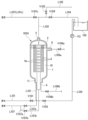
- FIG. 1 is a schematic diagram showing a water treatment facility according to an embodiment of the present invention.
- FIG. 2 is a schematic diagram showing a first membrane filtration device installed in a water treatment facility according to an embodiment of the present invention.
- FIG. 3 is a schematic diagram showing the main parts of the first membrane filtration device.
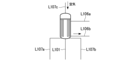
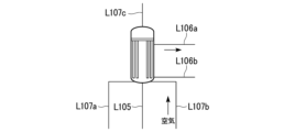
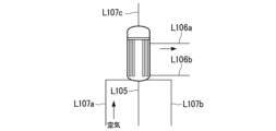
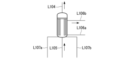
- FIG. 4A is a schematic diagram illustrating a method of operating a water treatment facility according to an embodiment of the present invention.
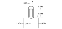
- FIG. 4B is a schematic diagram illustrating a method of operating a water treatment facility according to an embodiment of the present invention.
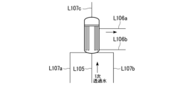
- FIG. 4C is a schematic diagram illustrating a method of operating a water treatment facility according to an embodiment of the present invention.
- FIG. 4A is a schematic diagram illustrating a method of operating a water treatment facility according to an embodiment of the present invention.
- FIG. 4B is a schematic diagram illustrating a method of operating a water treatment facility according to an embodiment of the present invention.
- FIG. 4C is a schematic diagram illustrating a
- FIG. 4D is a schematic diagram illustrating a method of operating a water treatment facility according to an embodiment of the present invention.
- FIG. 5A is a schematic diagram illustrating a method of operating a water treatment facility according to an embodiment of the present invention.
- FIG. 5B is a schematic diagram illustrating a method of operating a water treatment facility according to an embodiment of the present invention.
- FIG. 5C is a schematic diagram illustrating a method of operating a water treatment facility according to an embodiment of the present invention.
- FIG. 5D is a schematic diagram illustrating a method of operating a water treatment facility according to an embodiment of the present invention.
- FIG. 6A is a schematic diagram illustrating a method of operating a water treatment facility according to an embodiment of the present invention.
- FIG. 6B is a schematic diagram illustrating a method of operating a water treatment facility according to an embodiment of the present invention.
- FIG. 7 is a schematic diagram showing a conventional water treatment facility.
- the water treatment equipment 100 of this embodiment includes a first membrane filtration device 102, a second membrane filtration device 103 installed after the first membrane filtration device 102, and permeated water that has passed through the first membrane filtration device 102.
- a treated water tank 104 is provided downstream of the second membrane filtration device 103. Furthermore, the water treatment equipment 100 is equipped with an air supply section 107 that supplies air to the first membrane filtration device 102, and a wash water discharge section 106 that discharges the wash water from the first membrane filtration device 102. There is.
- the first membrane filtration device 102 filters raw water to produce primary permeated water
- the second membrane filtration device 103 filters the primary permeated water to produce secondary permeated water.
- a portion of the primary permeated water prepared by the first membrane filtration device 102 is temporarily stored in a storage tank 105.
- primary permeated water is circulated between the first membrane filtration device 102 and the storage tank 105.
- the water treatment facility 100 shown in FIG. 1 is equipped with flow paths L101 to L107. These channels are of a closed type. These channels interconnect the raw water tank 101, the first membrane filtration device 102, the second membrane filtration device 103, the treated water tank 104, the storage tank 105, the air supply section 107, and the wash water discharge section 106, respectively. There is. Further, the flow paths L102 and L104 are provided with valves V102 and V104.
- the circulation flow path L110 is composed of a first circulation flow path and a second circulation flow path.
- the first circulation flow path consists of a part of the flow path L102 and a flow path L104 branched from the flow path L102, and supplies a portion of the primary permeated water prepared by the first membrane filtration device 102 to the storage tank 105.
- the second circulation flow path includes a flow path L105, and enables the primary permeated water stored in the storage tank 105 to be supplied to the primary side of the first membrane filtration device 102.
- the circulation flow path L110 also includes a storage tank 105.
- a pump P3 for circulating primary permeated water between the first membrane filtration device 102 and the storage tank 105 is provided in the flow path L105 (second circulation flow path).
- the circulation channel L110 is a closed channel.
- the first membrane filtration device 102 is composed of a plurality of membrane filtration units 102A and 102B that are connected in parallel to each other.
- the circulation flow path L110 is capable of supplying primary permeated water to each of the membrane filtration units 102A and 102B.
- the flow paths L101 and L102 are equipped with pumps P1 and P2, respectively.
- the pump P1 pressurizes raw water and supplies it to the primary side of the first membrane filtration device 102.
- the pump P2 pressurizes the primary permeated water and supplies it to the primary side of the second membrane filtration device 103.
- a VVVF inverter device 113 is attached to the pump P2.
- the flow path L103 is equipped with a flow meter 114.
- the flow rate measurement result by the flow meter 114 is configured to be output to the VVVF inverter device 113.
- the VVVF inverter device 113 is configured to control the pump P2 based on the flow rate measurement result. Thereby, the amount of water supplied to the second membrane filtration device 103 is controlled.
- the storage tank 105 temporarily stores the primary permeated water prepared by the first membrane filtration device 102.
- the storage tank 105 forms a part of the circulation flow path L110.
- the storage tank 105 is an open type storage tank. Thereby, in the operating method described later, when primary permeated water mixed with air bubbles is circulated, air bubbles are degassed in the storage tank 105.
- the first membrane filtration device 102 is composed of a plurality of membrane filtration units 102A and 102B connected in parallel. Although two membrane filtration units 102A and 102B are shown in FIG. 2, the number of membrane filtration units is not limited to two, but may be three, four, or five or more.
- FIG. 3 shows an enlarged cross-sectional view of the membrane filtration unit 102A. Note that the structure of the membrane filtration unit 102B is the same as that of the membrane filtration unit 102A.
- the membrane filtration unit 102A includes a container 1 arranged with the axial direction of the cylinder in the vertical direction (vertical direction in this embodiment). A plurality of hollow fiber membranes 2 are arranged within this container 1 .
- the hollow fiber membrane 2 is fixed on the upper side of the container 1 by a synthetic resin potting part 3 as a fixing part, and is not fixed on the lower side of the container 1.
- a synthetic resin potting part 3 as a fixing part
- epoxy resin can be used as the synthetic resin for the potting portion 3.
- the hollow fiber membrane 2 is assembled in a U-shape, and both ends of the hollow fiber membrane 2 are fixed with potting parts 3. In this case, the middle part of the hollow fiber membrane 2 is located at the bottom of the container 1.
- the hollow fiber membrane 2 is, for example, an ultrafiltration membrane (UF membrane).
- UF membranes include those having pores of 0.005 to 0.5 ⁇ m.
- a membrane having an inner diameter of 0.2 to 1.0 mm, an outer diameter of 0.5 to 2.0 mm, and an effective length of about 300 to 2500 mm is usually used.
- the membrane material of the UF membrane but PVDF (polyvinylidene fluoride), polyethylene, polypropylene, etc. can be used.
- the UF membrane provided in the first membrane filtration device 102 is not limited to a hollow fiber membrane, and may be a spiral membrane, a tubular membrane, or a flat membrane.
- a treated water chamber (permeated water chamber) 7 and a raw water chamber 10 are defined on the upper and lower sides of the potting section 3, respectively.
- the upper end side of the hollow fiber membrane 2 passes through the potting part 3, the opening at the upper end faces the treated water chamber 7, and the inside of the hollow fiber membrane 2 communicates with the treated water chamber 7.
- both ends of the hollow fiber membrane 2 penetrate the potting part 3.
- the raw water chamber 10 is the primary side of the hollow fiber membrane 2
- the permeated water chamber 7 is the secondary side of the hollow fiber membrane 2.
- the potting part 3 is, for example, disc-shaped, and its outer peripheral surface or outer peripheral edge is in watertight contact with the inner surface of the container 1.
- a central pipe 4 extends substantially vertically (in the axial direction of the container 1).
- the central tube 4 is arranged, for example, along the central axis of the container 1.
- the central tube 4 is a circular tube with a closed tip (upper end), and a plurality of ejection holes 4a are provided throughout the side circumferential surface at intervals in the upper and lower directions and in the circumferential direction.
- the height (length in the vertical direction) of the center tube 4 is not particularly limited, it is preferable that the upper end of the center tube 4 is located near the lower surface of the potting section 3. Note that the upper end of the central tube 4 may be buried in the potting part 3.
- connection state between the membrane filtration unit 102A and the channels L101, L102, L104 (first circulation channel), L105 (second circulation channel), L106 (L106a, L106b), and L107 (L107a, L107b) explain.
- the connection state between the membrane filtration unit 102B and each channel is the same as that of the membrane filtration unit 102A.
- a flow path L101 is connected to the opening 11, and a valve V101 is provided in the flow path L101.
- a flow path L105 joins the flow path L101 on the side closer to the container 1 than the valve V101.
- the flow path L101 is connected to the raw water tank 101. In the water passage step, raw water is supplied from the raw water tank 101 to the inside of the container 1 (raw water chamber 10 (primary side)) through the flow path L101.
- the flow path L105 (second circulation flow path) is connected to the storage tank 105.
- primary permeated water permeated water
- the primary permeated water supplied to the raw water chamber 10 is filtered by the hollow fiber membrane 2 and sent to the outside of the container 1 via the permeated water chamber 7.
- raw water can be supplied from the lower part of the raw water chamber 10 by opening the valve V101, closing the valve V105, and sending the raw water through the flow path L101 by the pump P1.
- primary permeated water can be supplied from the lower part of the raw water chamber 10 by closing the valve V101, opening the valve V105, and sending out the primary permeated water via the flow path L105 using the pump P3.
- a flow path L107a is connected to the opening 11, and a valve V107a is provided in the flow path L107a.
- a flow path L107b is connected to the lower part of the central pipe 4, and a valve V107b is provided in the flow path L107b.
- Flow paths L107a and L107b are branched from flow path L107.
- the flow path L107 is connected to the air supply section 107. Thereby, air is supplied from the air supply section 107 to the inside of the container 1 (raw water chamber 10) via the flow path L107 and the flow path L107a. Furthermore, air is supplied to the central tube 4 via the flow path L107 and the flow path L107b.
- the air supply route to the container 1 can be switched.
- opening the valve V107a and closing the valve V107b air can be supplied from the lower side of the inside of the container 1 (raw water chamber 10) through the opening 11.
- closing the valve V107a and opening the valve V107b air can be supplied from the upper side of the inside of the container 1 (raw water chamber 10) via the central pipe 4.
- supplying air from the channel L107a or L107b while the inside of the container 1 (raw water chamber 10) is filled with water air bubbles are supplied from the opening 11 or the central pipe 4, and the central thread membrane 2 is Bubbling cleaning is also possible.
- an upper discharge port 8 is provided at the upper side of the container 1.
- the upper discharge port 8 is provided near the bottom surface of the potting section 3.
- a flow path L106a is connected to the upper discharge port 8, and a valve V106a is provided in the flow path L106a.
- a flow path L106b is connected to the opening 11, and a valve V106b is provided in the flow path L106b.
- the flow paths L106a and L106b merge to form a flow path L106, which is connected to the drainage tank 106a of the wash water discharge section 106. Washing waste water or air inside the container 1 (raw water chamber 10) is discharged through the flow paths L106a, L106b, and L106.
- the discharge path of either or both of the cleaning waste water and air from the container 1 can be switched.
- the valve V106a and closing the valve V106b either or both of the cleaning waste water and air can be discharged from the upper side of the container 1 through the upper discharge port 8.
- closing the valve V106a and opening the valve V106b either or both of the cleaning waste water and air can be discharged from the lower side of the container 1 through the opening 11.
- the cleaning waste water is sent to the waste water tank 106a via the flow path L106.
- An outlet 5 for primary permeate water is provided at the top of the container 1.
- a flow path L102 is connected to the outlet 5.
- the primary permeated water is taken out of the container 1 via the flow path L102 and sent to the second membrane filtration device 103.
- a flow path L107c is branched off in the middle of the flow path L102.
- a valve V107c is provided in the flow path L107c.
- the flow path L107c is connected to the air supply section 107.
- a flow path L104 is branched off in the middle of the flow path L102.
- a valve V102 is provided in the flow path L102 downstream of this branch point, and a valve V104 is provided in the flow path L104.
- Flow path L104 is connected to storage tank 105.
- the supply destination of the primary permeated water can be switched to the second membrane filtration device 103 or the storage tank 105.
- primary permeated water can be supplied to the second membrane filtration device 103 by opening the valve V102 and closing the valve V104.
- primary permeated water can be supplied to the storage tank 105 by closing the valve V102 and opening the valve V104.
- air can be supplied to the inside of the container 1 (permeated water chamber 7) via the outlet 5 by opening the valve V107c with the valves V102 and V104 closed.
- the central thread membrane 2 can be backwashed with air.
- the flow path L102 needs to extend vertically from the outlet 5 at the top of the container 1 to a certain length. Further, the outlet 5 of the container 1 needs to be provided at the top end of the container 1. In the operating method of this embodiment, it is necessary to circulate the primary permeated water to exhaust the air remaining in the container 1 in the air bleeding step, but the flow path L102 is made to extend vertically to a certain length. This makes it possible for air to be quickly discharged from the container 1 toward the flow path L102 due to its own buoyancy.
- the second membrane filtration device 103 shown in FIG. 1 prepares secondary permeated water by filtering the primary permeated water.
- the second membrane filtration device 103 is equipped with a hollow fiber membrane.
- the hollow fiber membrane of the second membrane filtration device 103 is, for example, a reverse osmosis membrane (RO membrane).
- RO membrane reverse osmosis membrane
- the membrane material of the RO membrane but cellulose acetate, aromatic polyamide, etc. can be used.
- the RO membrane provided in the second membrane filtration device 103 is not limited to a hollow fiber membrane, and may be a spiral membrane or a tubular membrane.
- the treated water tank 104 stores the secondary permeated water prepared by the second membrane filtration device 103.
- the cleaning water discharge section 106 discharges cleaning waste water generated during the cleaning process of the first membrane filtration device 102.
- the first membrane filtration device 102 and the wash water discharge section 106 are connected by a flow path L106.
- the wash water discharge section 106 is equipped with a discharge tank 106a that temporarily stores wash water.
- the air supply unit 107 supplies air to the first membrane filtration device 102 during the cleaning process of the first membrane filtration device 102.
- the first membrane filtration device 102 and the air supply unit 107 are connected by a flow path L107.
- the control unit 110 transfers the primary permeated water stored in the storage tank 105 to the first membrane filtration device 102 via the circulation flow path L110.
- the pump P3 is controlled to circulate between the storage tank 105 and the storage tank 105. Further, the control unit 110 circulates the primary permeated water stored in the storage tank 105 between any one of the membrane filtration units 102A, 102B and the storage tank 105 via the circulation flow path L110.
- the operating method of the water treatment equipment 100 of the present embodiment includes a water flow process in which the primary permeated water filtered in the first membrane filtration device 102 is supplied to the second membrane filtration device 103, and a first water flow process in the middle of the water flow process.
- a cleaning step of cleaning the membrane filtration device 102 is provided.
- the cleaning process includes at least an air cleaning stage and an air removal stage. In the air cleaning step, the filtration membrane built in the first membrane filtration device 102 is cleaned using air.
- the primary permeated water is permeated from the primary side of the first membrane filtration device 102 to the filtration membrane, and the primary permeation is performed between the first membrane filtration device 102 and the storage tank 105. Circulate water.
- valve V102 In the water flow step, in FIG. 1, pumps P1 and P2 are operated, valve V102 is opened, and valve V104 is closed.
- raw water is supplied from the raw water tank 101 to the first membrane filtration device 102 via the flow path L101.
- the raw water is filtered by a UF membrane (hollow fiber membrane 2) provided in the first membrane filtration device 102 to become primary permeated water.
- the primary permeated water is sent to the second membrane filtration device 103 through the flow path L102.
- the primary permeated water is sent to the second membrane filtration device 103 in a pressurized state by a pump P2 provided in the middle of the flow path L102.
- the primary permeated water is filtered by an RO membrane provided in the second membrane filtration device 103 to become secondary permeated water.
- the secondary permeated water is sent to the treated water tank 104 through the flow path L103.
- valve V101 of flow path L101 and valve V102 of flow path L102 are opened.
- valve V105 of flow path L105 (second circulation flow path) and valve V104 of flow path L104 (first circulation flow path) are closed.
- valves V1107a to V107c of flow path L107 are closed, and valves V106a and V106b of flow paths L106a and L106b are closed.
- raw water is supplied to both membrane filtration units 102A and 102B through the flow path L101.
- Raw water is supplied to the raw water chamber 10 (primary side) of the container 1, and is filtered by the hollow fiber membrane 2 to become primary permeated water.
- the primary permeated water permeates through the hollow fiber membrane 2 and is taken out into the permeated water chamber 7 (secondary side) of the container 1. Then, it is sent to the second membrane filtration device 103 through the flow path L102.
- suspended solids By continuing the water passage process, suspended solids, organic matter, etc. contained in the raw water (hereinafter referred to as suspended solids) gradually accumulate on the primary side of the hollow fiber membrane 2. Therefore, in order to prevent clogging of the hollow fiber membrane 2, a cleaning step is performed.
- the cleaning step is performed on one of the plurality of membrane filtration units 102A and 102B provided in the first membrane filtration device 102, and the water passage step is continued in the other membrane filtration units.
- the water passing step can be continued in parallel with the washing step, and the preparation of the primary permeated water can be continued without interruption.
- the cleaning process may be performed on one membrane filtration unit, and the water passage process may be continued on the remaining units.
- a cleaning process is performed on the membrane filtration unit 102A, and a water passage process is continued on the membrane filtration unit 102B.
- an air cleaning stage and an air bleeding stage are performed sequentially.
- the hollow fiber membrane 2 (filtration membrane) built in the first membrane filtration device 102 is cleaned using air.
- air backwashing is performed by supplying air from the secondary side of the hollow fiber membrane 2
- air washing is performed by supplying air to the primary side of the hollow fiber membrane 2 to clean the hollow fiber membrane 2
- air cleaning is performed by supplying air to the primary side of the hollow fiber membrane 2.
- bubbling cleaning is performed in which the hollow fiber membrane 2 is cleaned by blowing air into the hollow fiber membrane 2 filled with water.
- any one of air backwashing, air cleaning, and bubbling cleaning may be performed as filtration membrane cleaning using air, or two or more of them may be performed.
- water cleaning may be performed in which cleaning water is supplied to the primary side of the hollow fiber membrane 2 to clean the hollow fiber membrane 2.
- FIG. 4A shows the membrane filtration unit 102A in which the water flow process is continuing.
- Raw water is supplied to the raw water chamber 10 (primary side) through the flow path L101, filtered by the hollow fiber membrane 2, taken out as primary permeated water to the permeated water chamber 7 (secondary side), and discharged from the flow path L102.
- valves V101 and V102 are open, and the other valves are closed.
- the opening/closing status of the valve in the other membrane filtration unit 102B is the same as in the case of the membrane filtration unit 102A.
- the cleaning process for the membrane filtration unit 102A will be explained, but the opening/closing status of the valves in the membrane filtration unit 102B, which is continuing the water flow process, is maintained as it is.
- the valve V101 of the flow path L101 is closed to stop the supply of raw water, and the valve V102 of the flow path L102 is also closed. Further, the valve V106b of the flow path L106b is opened. As a result, as shown in FIG. 4B, the raw water filled in the raw water chamber 10 (primary side) is discharged from the raw water chamber 10 through the flow path L106b. The discharged raw water is sent to the wash water discharge section 106.
- Valve V105 of flow path L105 is closed while raw water chamber 10 is filled with primary permeated water. Pump P3 is stopped. Valve V107b of flow path L107b is opened. Valve V106a of flow path L106a remains open. Thereby, as shown in FIG. 5B, air is supplied from the flow path L107b to the raw water chamber 10 (primary side). Air is supplied to the central pipe 4 from the flow path L107b, and is ejected into the raw water chamber 10 from the ejection hole 4a provided in the central pipe 4.
- the ejected air forms bubbles and contacts the surface of the hollow fiber membrane 2 facing the central tube 4, thereby bubbling cleaning the upper part of the hollow fiber membrane 2. .
- the air used for cleaning is discharged from the flow path L106a together with some cleaning waste water. In this way, the upper part of the hollow fiber membrane 2 is cleaned by bubbling.
- Valve V107b of channel L107b is closed while raw water chamber 10 is filled with primary permeated water.
- Valve V107a of flow path L107a is opened.
- Valve V106a of flow path L106a remains open.
- air is supplied from the flow path L107a to the raw water chamber 10 (primary side). Air is supplied through the opening 11 at the bottom of the container 1. Since the raw water chamber 10 remains filled with the primary permeated water, the supplied air becomes bubbles and contacts the primary side surface of the hollow fiber membrane 2, thereby bubbling cleaning the lower part of the hollow fiber membrane 2.
- the air used for cleaning is discharged from the flow path L106a. In this way, the lower part of the hollow fiber membrane 2 is cleaned by bubbling.
- valve V107a of the flow path L107a is left open, the valve V106a of the flow path L106a is closed, and the valve V106b of the flow path L106b is opened.
- the cleaning water in the raw water chamber 10 is discharged from the flow path L106b while continuing bubbling cleaning to the lower part of the hollow fiber membrane 2.
- the entire hollow fiber membrane 2 can be cleaned by bubbling.
- the air bleed stage will be explained. Since air remains inside the membrane filtration unit 102A of the first membrane filtration device 102 after the air cleaning stage is completed, if the water flow process is restarted in this state, the primary permeated water containing air bubbles will flow into the flow path. It will be sent to pump P2 and second membrane filtration device 103 via L102. In this case, the primary permeated water containing air bubbles may cause abnormal operations of the pump P2 and the second membrane filtration device 103. Therefore, in this embodiment, air bubbles are completely removed from the inside of the membrane filtration unit 102A by performing an air bleeding process.
- valve V104 of flow path L104 first circulation flow path
- valve V105 of flow path L105 second circulation flow path
- the valve V106a of the flow path L106a is also opened.
- the valve V106b of the flow path L106b is closed, and the valve V1067a of the flow path L107a is also closed.
- pump P3 is activated.
- primary permeated water is supplied from the storage tank 105 to the raw water chamber 10 (primary side).
- a part of the primary permeated water is discharged from the flow path L106b.
- the discharged primary permeate water is sent to the wash water discharge section 106.
- the air remaining in the raw water chamber 10 (primary side) can be quickly discharged, and the raw water chamber 10 can be filled with primary permeated water.
- the remainder of the primary permeated water supplied to the raw water chamber 10 passes through the hollow fiber membrane 2 and is taken out from the permeated water chamber 7 (secondary side).
- the extracted primary permeated water is returned to the storage tank 105 through the flow path L104.
- the returned primary permeated water is sent to the membrane filtration unit 102A again through the flow path L105. In this way, the circulation of the primary permeate through the circulation channel is stabilized.
- valve V106a of the flow path L106a is closed.
- the valve V104 of the flow path L104 (first circulation flow path) and the valve V105 of the flow path L105 (second circulation flow path) are left open, and the pump P3 is also kept operating.
- the primary permeated water stored in the storage tank 105 is circulated between the storage tank 105 and the membrane filtration unit 102A through the circulation flow path L110.
- the flow path L102 extends vertically to a certain length from the outlet 5 at the top of the container 1, and since the outlet 5 of the container 1 is provided at the top end of the container 1, Due to the buoyancy of the air itself, air bubbles remaining inside the container 1 can be quickly discharged to the outside of the container 1.
- the discharged bubbles are sent to the storage tank 105 along with the primary permeated water through the flow path L104. Since the storage tank 105 is of an open type, air bubbles that reach the storage tank 105 are immediately degassed.
- the membrane filtration unit 102A should immediately proceed to the water passage process.
- the cleaning step may be performed sequentially on a plurality of membrane filtration units. That is, of course, after the cleaning process for the membrane filtration unit 102A is completed, the cleaning process for another membrane filtration unit 102B may be started. However, if the cleaning process for another membrane filtration unit 102B is started immediately after the cleaning process for the membrane filtration unit 102A is finished, the supply amount of the primary permeated water will fluctuate greatly, and the primary permeated water in the second membrane filtration device 103 will be There is a risk that the balance between the supply amount and the production amount of secondary permeated water will be lost, and the operation of the second membrane filtration device 103 will become unstable.
- all membrane filtration is It is preferable to perform a water passage process on the unit. That is, it is preferable to start the cleaning process for the membrane filtration unit 102B after the cleaning process for the membrane filtration unit 102A is completed and the membrane filtration unit 102A moves to the water passage process. When the membrane filtration unit 102A moves to the water passage process, the water passage process is also in progress in the membrane filtration unit 102B. In this way, it is preferable to perform the next cleaning process once all membrane filtration units have transitioned to the water passage process.
- the circulation channel allows the primary permeated water stored in the storage tank 105 to be circulated between the first membrane filtration device 102 and the storage tank 105.
- L110, pump P3, and control unit 110 even when cleaning the first membrane filtration device 102 with air introduction, air bubbles remaining in the first membrane filtration device 102 can be removed. Can be removed early.
- the water treatment equipment 100 can be made more compact.
- the circulation flow path L110 is a first circulation flow path that supplies primary permeated water to the storage tank 105, and a second circulation path that allows the primary permeation water stored in the storage tank 105 to be supplied to the first membrane filtration device 102. Since the primary permeated water circulation path is shortened, the water treatment equipment 100 can be made compact.
- the storage tank 105 is an open type storage tank, air bubbles contained in the primary permeated water can be released in the storage tank 105. Furthermore, since the circulation flow path L110 is a closed flow path, it is possible to suppress air bubbles from entering from the outside.
- the first membrane filtration device 102 is composed of a plurality of membrane filtration units 102A and 102B that are connected in parallel to each other, and the circulation flow path L110 is connected to the primary permeated water for each of the membrane filtration units 102A and 102B.
- the control unit 110 circulates the primary permeated water stored in the storage tank 105 between any one membrane filtration unit and the storage tank 105 via the circulation flow path L110. Even if one membrane filtration unit is in the cleaning process, the water passing process can be continued in other membrane filtration units, so the production amount of secondary permeated water is not reduced.
- the cleaning process includes cleaning the first membrane filtration device 102 during the water flow process, and the cleaning process includes at least the first membrane filtration device 102.
- the storage tank 105 is an open type storage tank, air bubbles contained in the primary permeated water can be released in the storage tank 105.
- the first membrane filtration device 102 is composed of a plurality of membrane filtration units 102A and 102B that are connected in parallel to each other, and the circulation flow path L110 can supply primary permeated water to each of the membrane filtration units 102A and 102B.
- the cleaning process is performed on some of the membrane filtration units 102A, and the water passing process is performed on the remaining membrane filtration units 102B, so the production amount of secondary permeated water is reduced. will not deteriorate.
- 100... Water treatment device 101... Raw water tank, 102... First membrane filtration device, 102A, 102B... Membrane filtration unit, 103... Second membrane filtration device, 104... Treated water tank, 105... Storage tank, L110... Circulation channel , P3...pump, 110...control unit, L102, L104...first circulation flow path, L105...second circulation flow path.
Landscapes
- Engineering & Computer Science (AREA)
- Water Supply & Treatment (AREA)
- Chemical & Material Sciences (AREA)
- Chemical Kinetics & Catalysis (AREA)
- Life Sciences & Earth Sciences (AREA)
- Hydrology & Water Resources (AREA)
- Environmental & Geological Engineering (AREA)
- Organic Chemistry (AREA)
- Nanotechnology (AREA)
- Separation Using Semi-Permeable Membranes (AREA)
- Physical Water Treatments (AREA)
- Degasification And Air Bubble Elimination (AREA)
Abstract
Description
本願は、2022年4月26日に、日本に出願された特願2022-72081号に基づき優先権を主張し、その内容をここに援用する。
[1] 第1膜ろ過装置と、
前記第1膜ろ過装置の後段に設置された第2膜ろ過装置と、
前記第1膜ろ過装置を透過した透過水の一部が貯留される貯留槽と、
前記第1膜ろ過装置と前記貯留槽との間に設置されて、前記貯留槽に貯留された前記透過水を、前記第1膜ろ過装置と前記貯留槽との間で循環可能とする循環流路と、
前記循環流路に備えられたポンプと、
前記第1膜ろ過装置に対する空気導入を伴うろ過膜洗浄の終了後に、前記貯留槽に貯留された前記透過水を、前記循環流路を介して、前記第1膜ろ過装置と前記貯留槽との間で循環させるように前記ポンプを制御する制御部と、を備えた水処理設備。
[2] 前記循環流路は、
前記第1膜ろ過装置を透過した前記透過水を前記貯留槽に供給する第1循環流路と、
前記貯留槽に貯留された前記透過水を前記第1膜ろ過装置の一次側に供給可能にする第2循環流路と、から構成され、
前記第2循環流路に前記ポンプが備えられている、[1]に記載の水処理設備。
[3] 前記循環流路が閉鎖型の流路であり、前記貯留槽が開放型の貯留槽である、[1]または[2]に記載の水処理設備。
[4] 前記第1膜ろ過装置は、相互に並列接続された複数の膜ろ過ユニットから構成され、
前記循環流路は、前記膜ろ過ユニットのそれぞれに対して前記透過水を供給可能とされ、
前記制御部は、前記貯留槽に貯留された前記透過水を、前記循環流路を介して、いずれか1つの前記膜ろ過ユニットと前記貯留槽との間で循環させる、[1]または[2]に記載の水処理設備。
[5] 第1膜ろ過装置と、前記第1膜ろ過装置の後段に設置された第2膜ろ過装置と、前記第1膜ろ過装置を透過した透過水の一部が貯留される貯留槽と、が備えられた水処理設備の運転方法であって、
前記第1膜ろ過装置においてろ過された前記透過水を前記第2膜ろ過装置に供給する通水工程と、
前記通水工程の途中において、前記第1膜ろ過装置に対してろ過膜洗浄を行う洗浄工程と、を備え、
前記洗浄工程には、少なくとも、
前記第1膜ろ過装置に対して空気を用いたろ過膜洗浄を行うエア洗浄段階と、
前記エア洗浄段階の後に、前記第1膜ろ過装置の一次側から前記透過水を透過させつつ、前記第1膜ろ過装置と前記貯留槽との間で前記透過水を循環流路により循環させるエア抜き段階と、が備えられている、水処理設備の運転方法。
[6] 前記貯留槽が開放型の貯留槽とされており、
前記エア抜き工程において前記第1膜ろ過装置から前記透過水とともに排出された空気を、前記貯留槽において脱気する、[5]に記載の水処理設備の運転方法。
[7] 前記第1膜ろ過装置は、相互に並列接続された複数の膜ろ過ユニットから構成され、
前記循環流路は、前記複数の膜ろ過ユニットそれぞれに対して前記透過水を供給可能とされ、
前記複数の膜ろ過ユニットのうち、一部の膜ろ過ユニットに対して前記洗浄工程を行うともに、残りの膜ろ過ユニットに対して前記通水工程を行う、[5]または[6]に記載の水処理設備の運転方法。
[8] 前記複数の膜ろ過ユニットに対して、順次、洗浄工程を行う場合において、膜ろ過ユニットに対する先行の洗浄工程と、別の膜ろ過ユニットに対する後行の洗浄工程との間で、全ての膜ろ過ユニットに対して通水工程を行う、[7]に記載の水処理設備の運転方法。
本実施形態の水処理設備100は、第1膜ろ過装置102と、第1膜ろ過装置102の後段に設置された第2膜ろ過装置103と、第1膜ろ過装置102を透過した透過水の一部が貯留される貯留槽105と、第1膜ろ過装置102と貯留槽105との間に設置された循環流路L110と、循環流路L110に備えられたポンプP3と、制御部110と、が備えられている。また、第1膜ろ過装置102の前段には原水槽101が備えられている。更に、第2膜ろ過装置103の後段には処理水槽104が備えられている。更にまた、水処理設備100には、第1膜ろ過装置102に空気を供給する空気供給部107と、第1膜ろ過装置102からの洗浄水を排出する洗浄水排出部106とが備えられている。
本実施形態の水処理設備100の運転方法は、第1膜ろ過装置102においてろ過された一次透過水を第2膜ろ過装置103に供給する通水工程と、通水工程の途中において、第1膜ろ過装置102に対してろ過膜洗浄を行う洗浄工程と、を備える。洗浄工程には、少なくとも、エア洗浄段階と、エア抜き段階とが備えられている。エア洗浄段階は、第1膜ろ過装置102に内蔵されたろ過膜に対して空気を用いたろ過膜洗浄を行う。エア抜き段階は、エア洗浄段階の後に、第1膜ろ過装置102の一次側からろ過膜に対して一次透過水を透過させつつ、第1膜ろ過装置102と貯留槽105との間で一次透過水を循環させる。
通水工程では、図2および図3において、流路L101の弁V101および流路L102の弁V102を開にする。一方、流路L105(第2循環流路)の弁V105および流路L104(第1循環流路)の弁V104を閉にする。また、流路L107の弁V1107a~V107cを閉とし、流路L106aおよびL106bの弁V106aおよびV106bを閉とする。
Claims (8)
- 第1膜ろ過装置と、
前記第1膜ろ過装置の後段に設置された第2膜ろ過装置と、
前記第1膜ろ過装置を透過した透過水の一部が貯留される貯留槽と、
前記第1膜ろ過装置と前記貯留槽との間に設置されて、前記貯留槽に貯留された前記透過水を、前記第1膜ろ過装置と前記貯留槽との間で循環可能とする循環流路と、
前記循環流路に備えられたポンプと、
前記第1膜ろ過装置に対する空気導入を伴うろ過膜洗浄の終了後に、前記貯留槽に貯留された前記透過水を、前記循環流路を介して、前記第1膜ろ過装置と前記貯留槽との間で循環させるように前記ポンプを制御する制御部と、を備えた水処理設備。 - 前記循環流路は、
前記第1膜ろ過装置を透過した前記透過水を前記貯留槽に供給する第1循環流路と、
前記貯留槽に貯留された前記透過水を前記第1膜ろ過装置の一次側に供給可能にする第2循環流路と、から構成され、
前記第2循環流路に前記ポンプが備えられている、請求項1に記載の水処理設備。 - 前記循環流路が閉鎖型の流路であり、前記貯留槽が開放型の貯留槽である、請求項1または請求項2に記載の水処理設備。
- 前記第1膜ろ過装置は、相互に並列接続された複数の膜ろ過ユニットから構成され、
前記循環流路は、前記膜ろ過ユニットのそれぞれに対して前記透過水を供給可能とされ、
前記制御部は、前記貯留槽に貯留された前記透過水を、前記循環流路を介して、いずれか1つの前記膜ろ過ユニットと前記貯留槽との間で循環させる、請求項1または請求項2に記載の水処理設備。 - 第1膜ろ過装置と、前記第1膜ろ過装置の後段に設置された第2膜ろ過装置と、前記第1膜ろ過装置を透過した透過水の一部が貯留される貯留槽と、が備えられた水処理設備の運転方法であって、
前記第1膜ろ過装置においてろ過された前記透過水を前記第2膜ろ過装置に供給する通水工程と、
前記通水工程の途中において、前記第1膜ろ過装置に対してろ過膜洗浄を行う洗浄工程と、を備え、
前記洗浄工程には、少なくとも、
前記第1膜ろ過装置に対して空気を用いたろ過膜洗浄を行うエア洗浄段階と、
前記エア洗浄段階の後に、前記第1膜ろ過装置の一次側から前記透過水を透過させつつ、前記第1膜ろ過装置と前記貯留槽との間で前記透過水を循環流路により循環させるエア抜き段階と、が備えられている、水処理設備の運転方法。 - 前記貯留槽が開放型の貯留槽とされており、
前記エア抜き工程において前記第1膜ろ過装置から前記透過水とともに排出された空気を、前記貯留槽において脱気する、請求項5に記載の水処理設備の運転方法。 - 前記第1膜ろ過装置は、相互に並列接続された複数の膜ろ過ユニットから構成され、
前記循環流路は、前記複数の膜ろ過ユニットそれぞれに対して前記透過水を供給可能とされ、
前記複数の膜ろ過ユニットのうち、一部の膜ろ過ユニットに対して前記洗浄工程を行うともに、残りの膜ろ過ユニットに対して前記通水工程を行う、請求項5または請求項6に記載の水処理設備の運転方法。 - 前記複数の膜ろ過ユニットに対して、順次、洗浄工程を行う場合において、膜ろ過ユニットに対する先行の洗浄工程と、別の膜ろ過ユニットに対する後行の洗浄工程との間で、全ての膜ろ過ユニットに対して通水工程を行う、請求項7に記載の水処理設備の運転方法。
Priority Applications (3)
| Application Number | Priority Date | Filing Date | Title |
|---|---|---|---|
| CN202380035492.5A CN119053557A (zh) | 2022-04-26 | 2023-04-21 | 水处理设备和水处理设备的运转方法 |
| US18/860,005 US20250288958A1 (en) | 2022-04-26 | 2023-04-21 | Water treatment facility and method for operating water treatment facility |
| KR1020247034707A KR20250003600A (ko) | 2022-04-26 | 2023-04-21 | 물 처리설비 및 물 처리설비의 운전방법 |
Applications Claiming Priority (2)
| Application Number | Priority Date | Filing Date | Title |
|---|---|---|---|
| JP2022-072081 | 2022-04-26 | ||
| JP2022072081A JP7396395B2 (ja) | 2022-04-26 | 2022-04-26 | 水処理設備および水処理設備の運転方法 |
Publications (1)
| Publication Number | Publication Date |
|---|---|
| WO2023210530A1 true WO2023210530A1 (ja) | 2023-11-02 |
Family
ID=88518921
Family Applications (1)
| Application Number | Title | Priority Date | Filing Date |
|---|---|---|---|
| PCT/JP2023/015951 Ceased WO2023210530A1 (ja) | 2022-04-26 | 2023-04-21 | 水処理設備および水処理設備の運転方法 |
Country Status (6)
| Country | Link |
|---|---|
| US (1) | US20250288958A1 (ja) |
| JP (1) | JP7396395B2 (ja) |
| KR (1) | KR20250003600A (ja) |
| CN (1) | CN119053557A (ja) |
| TW (1) | TW202400523A (ja) |
| WO (1) | WO2023210530A1 (ja) |
Citations (7)
| Publication number | Priority date | Publication date | Assignee | Title |
|---|---|---|---|---|
| JP2000246069A (ja) * | 1999-02-25 | 2000-09-12 | Japan Organo Co Ltd | 膜ろ過装置 |
| JP2004216264A (ja) * | 2003-01-14 | 2004-08-05 | Miura Co Ltd | 逆洗用エアタンクを備えた中空糸膜ろ過装置 |
| WO2009008463A1 (ja) * | 2007-07-12 | 2009-01-15 | Toray Industries, Inc. | 膜分離装置及びろ過処理方法 |
| WO2013047466A1 (ja) * | 2011-09-29 | 2013-04-04 | 東レ株式会社 | 膜モジュールの洗浄方法 |
| JP2016022448A (ja) * | 2014-07-23 | 2016-02-08 | 栗田工業株式会社 | 水処理装置及び水処理設備の洗浄方法 |
| JP2016215089A (ja) * | 2015-05-15 | 2016-12-22 | 株式会社クラレ | 中空糸膜モジュールの運転方法及び濾過装置 |
| WO2021065422A1 (ja) * | 2019-10-04 | 2021-04-08 | 栗田工業株式会社 | 膜濾過装置 |
Family Cites Families (5)
| Publication number | Priority date | Publication date | Assignee | Title |
|---|---|---|---|---|
| JP3003429U (ja) * | 1994-04-22 | 1994-10-18 | 株式会社サンワード | 脱気装置 |
| JP5245216B2 (ja) * | 2006-06-16 | 2013-07-24 | 富士電機株式会社 | 中空糸膜の水処理方法及び水処理装置 |
| JP6319493B1 (ja) * | 2017-03-29 | 2018-05-09 | 栗田工業株式会社 | 中空糸膜モジュールの洗浄方法 |
| WO2020194820A1 (ja) | 2019-03-27 | 2020-10-01 | 栗田工業株式会社 | 中空糸膜モジュール及びその洗浄方法 |
| CN210528686U (zh) * | 2019-07-15 | 2020-05-15 | 浙江东洋环境工程有限公司 | 铝业废水处理及回用系统 |
-
2022
- 2022-04-26 JP JP2022072081A patent/JP7396395B2/ja active Active
-
2023
- 2023-04-21 CN CN202380035492.5A patent/CN119053557A/zh active Pending
- 2023-04-21 US US18/860,005 patent/US20250288958A1/en active Pending
- 2023-04-21 WO PCT/JP2023/015951 patent/WO2023210530A1/ja not_active Ceased
- 2023-04-21 KR KR1020247034707A patent/KR20250003600A/ko active Pending
- 2023-04-25 TW TW112115303A patent/TW202400523A/zh unknown
Patent Citations (7)
| Publication number | Priority date | Publication date | Assignee | Title |
|---|---|---|---|---|
| JP2000246069A (ja) * | 1999-02-25 | 2000-09-12 | Japan Organo Co Ltd | 膜ろ過装置 |
| JP2004216264A (ja) * | 2003-01-14 | 2004-08-05 | Miura Co Ltd | 逆洗用エアタンクを備えた中空糸膜ろ過装置 |
| WO2009008463A1 (ja) * | 2007-07-12 | 2009-01-15 | Toray Industries, Inc. | 膜分離装置及びろ過処理方法 |
| WO2013047466A1 (ja) * | 2011-09-29 | 2013-04-04 | 東レ株式会社 | 膜モジュールの洗浄方法 |
| JP2016022448A (ja) * | 2014-07-23 | 2016-02-08 | 栗田工業株式会社 | 水処理装置及び水処理設備の洗浄方法 |
| JP2016215089A (ja) * | 2015-05-15 | 2016-12-22 | 株式会社クラレ | 中空糸膜モジュールの運転方法及び濾過装置 |
| WO2021065422A1 (ja) * | 2019-10-04 | 2021-04-08 | 栗田工業株式会社 | 膜濾過装置 |
Also Published As
| Publication number | Publication date |
|---|---|
| JP7396395B2 (ja) | 2023-12-12 |
| JP2023161633A (ja) | 2023-11-08 |
| US20250288958A1 (en) | 2025-09-18 |
| CN119053557A (zh) | 2024-11-29 |
| TW202400523A (zh) | 2024-01-01 |
| KR20250003600A (ko) | 2025-01-07 |
Similar Documents
| Publication | Publication Date | Title |
|---|---|---|
| JP4611982B2 (ja) | 逆洗方法 | |
| CA2425167A1 (en) | System and method for withdrawing permeate through a filter and for cleaning the filter in situ | |
| EA036835B1 (ru) | Способ фильтрации воды | |
| KR102349872B1 (ko) | 중공사막 모듈의 세정 방법 및 중공사막 여과 장치 | |
| JP2007528290A (ja) | 膜フィルタ洗浄方法および同方法を実施するための装置 | |
| KR20100127885A (ko) | 중공사막 여과 장치 | |
| JP2016068046A (ja) | 縦置き型外圧型中空糸膜モジュールおよびその運転方法 | |
| JP7396395B2 (ja) | 水処理設備および水処理設備の運転方法 | |
| US20250312746A1 (en) | Membrane filtration system | |
| JP2018023965A (ja) | 外圧式濾過モジュールの洗浄方法及び濾過装置 | |
| WO2017046214A1 (en) | Filtration system and method for backwashing a filtration system | |
| KR102379631B1 (ko) | 양돈 또는 축산용 소형 폐수 처리장치 | |
| JP7352125B2 (ja) | 膜分離装置および膜分離方法 | |
| JP5918033B2 (ja) | 油分含有排水の処理方法及び処理装置 | |
| JP5949834B2 (ja) | 中空糸膜モジュール及びその洗浄方法 | |
| JP2019018162A (ja) | 中空糸膜濾過装置の洗浄方法及び中空糸膜濾過装置 | |
| KR20130128866A (ko) | 가압형 막 모듈을 이용한 수처리 시스템 및 수처리 방법 | |
| JP6692702B2 (ja) | 中空糸膜モジュールの洗浄方法 | |
| JP7122915B2 (ja) | ろ過ユニットの洗浄方法 | |
| JPH1043553A (ja) | 濾過装置及び濾過方法 | |
| JP2005270810A (ja) | 濾過装置 | |
| KR20210141912A (ko) | 중공사막 모듈 및 그 세정 방법 | |
| KR101009470B1 (ko) | 중공사막 수처리 장치 | |
| JP2026017561A (ja) | 膜ろ過装置及びろ過膜の洗浄方法 | |
| JP2017217581A (ja) | 中空糸膜濾過装置及びその洗浄方法 |
Legal Events
| Date | Code | Title | Description |
|---|---|---|---|
| 121 | Ep: the epo has been informed by wipo that ep was designated in this application |
Ref document number: 23796272 Country of ref document: EP Kind code of ref document: A1 |
|
| WWE | Wipo information: entry into national phase |
Ref document number: 202380035492.5 Country of ref document: CN |
|
| WWE | Wipo information: entry into national phase |
Ref document number: 18860005 Country of ref document: US |
|
| NENP | Non-entry into the national phase |
Ref country code: DE |
|
| WWE | Wipo information: entry into national phase |
Ref document number: 11202407485Y Country of ref document: SG |
|
| 122 | Ep: pct application non-entry in european phase |
Ref document number: 23796272 Country of ref document: EP Kind code of ref document: A1 |
|
| WWP | Wipo information: published in national office |
Ref document number: 18860005 Country of ref document: US |