WO2023210375A1 - Instrument à cordes et lecteur phonographique - Google Patents
Instrument à cordes et lecteur phonographique Download PDFInfo
- Publication number
- WO2023210375A1 WO2023210375A1 PCT/JP2023/014896 JP2023014896W WO2023210375A1 WO 2023210375 A1 WO2023210375 A1 WO 2023210375A1 JP 2023014896 W JP2023014896 W JP 2023014896W WO 2023210375 A1 WO2023210375 A1 WO 2023210375A1
- Authority
- WO
- WIPO (PCT)
- Prior art keywords
- piezoelectric element
- groove
- saddle
- width
- porous layer
- Prior art date
- Legal status (The legal status is an assumption and is not a legal conclusion. Google has not performed a legal analysis and makes no representation as to the accuracy of the status listed.)
- Ceased
Links
Images





Classifications
-
- G—PHYSICS
- G10—MUSICAL INSTRUMENTS; ACOUSTICS
- G10D—STRINGED MUSICAL INSTRUMENTS; WIND MUSICAL INSTRUMENTS; ACCORDIONS OR CONCERTINAS; PERCUSSION MUSICAL INSTRUMENTS; AEOLIAN HARPS; SINGING-FLAME MUSICAL INSTRUMENTS; MUSICAL INSTRUMENTS NOT OTHERWISE PROVIDED FOR
- G10D3/00—Details of, or accessories for, stringed musical instruments, e.g. slide-bars
- G10D3/04—Bridges
-
- G—PHYSICS
- G10—MUSICAL INSTRUMENTS; ACOUSTICS
- G10H—ELECTROPHONIC MUSICAL INSTRUMENTS; INSTRUMENTS IN WHICH THE TONES ARE GENERATED BY ELECTROMECHANICAL MEANS OR ELECTRONIC GENERATORS, OR IN WHICH THE TONES ARE SYNTHESISED FROM A DATA STORE
- G10H3/00—Instruments in which the tones are generated by electromechanical means
- G10H3/12—Instruments in which the tones are generated by electromechanical means using mechanical resonant generators, e.g. strings or percussive instruments, the tones of which are picked up by electromechanical transducers, the electrical signals being further manipulated or amplified and subsequently converted to sound by a loudspeaker or equivalent instrument
- G10H3/14—Instruments in which the tones are generated by electromechanical means using mechanical resonant generators, e.g. strings or percussive instruments, the tones of which are picked up by electromechanical transducers, the electrical signals being further manipulated or amplified and subsequently converted to sound by a loudspeaker or equivalent instrument using mechanically actuated vibrators with pick-up means
- G10H3/143—Instruments in which the tones are generated by electromechanical means using mechanical resonant generators, e.g. strings or percussive instruments, the tones of which are picked up by electromechanical transducers, the electrical signals being further manipulated or amplified and subsequently converted to sound by a loudspeaker or equivalent instrument using mechanically actuated vibrators with pick-up means characterised by the use of a piezoelectric or magneto-strictive transducer
-
- G—PHYSICS
- G10—MUSICAL INSTRUMENTS; ACOUSTICS
- G10H—ELECTROPHONIC MUSICAL INSTRUMENTS; INSTRUMENTS IN WHICH THE TONES ARE GENERATED BY ELECTROMECHANICAL MEANS OR ELECTRONIC GENERATORS, OR IN WHICH THE TONES ARE SYNTHESISED FROM A DATA STORE
- G10H3/00—Instruments in which the tones are generated by electromechanical means
- G10H3/12—Instruments in which the tones are generated by electromechanical means using mechanical resonant generators, e.g. strings or percussive instruments, the tones of which are picked up by electromechanical transducers, the electrical signals being further manipulated or amplified and subsequently converted to sound by a loudspeaker or equivalent instrument
- G10H3/14—Instruments in which the tones are generated by electromechanical means using mechanical resonant generators, e.g. strings or percussive instruments, the tones of which are picked up by electromechanical transducers, the electrical signals being further manipulated or amplified and subsequently converted to sound by a loudspeaker or equivalent instrument using mechanically actuated vibrators with pick-up means
- G10H3/18—Instruments in which the tones are generated by electromechanical means using mechanical resonant generators, e.g. strings or percussive instruments, the tones of which are picked up by electromechanical transducers, the electrical signals being further manipulated or amplified and subsequently converted to sound by a loudspeaker or equivalent instrument using mechanically actuated vibrators with pick-up means using a string, e.g. electric guitar
-
- G—PHYSICS
- G10—MUSICAL INSTRUMENTS; ACOUSTICS
- G10H—ELECTROPHONIC MUSICAL INSTRUMENTS; INSTRUMENTS IN WHICH THE TONES ARE GENERATED BY ELECTROMECHANICAL MEANS OR ELECTRONIC GENERATORS, OR IN WHICH THE TONES ARE SYNTHESISED FROM A DATA STORE
- G10H3/00—Instruments in which the tones are generated by electromechanical means
- G10H3/12—Instruments in which the tones are generated by electromechanical means using mechanical resonant generators, e.g. strings or percussive instruments, the tones of which are picked up by electromechanical transducers, the electrical signals being further manipulated or amplified and subsequently converted to sound by a loudspeaker or equivalent instrument
- G10H3/14—Instruments in which the tones are generated by electromechanical means using mechanical resonant generators, e.g. strings or percussive instruments, the tones of which are picked up by electromechanical transducers, the electrical signals being further manipulated or amplified and subsequently converted to sound by a loudspeaker or equivalent instrument using mechanically actuated vibrators with pick-up means
- G10H3/18—Instruments in which the tones are generated by electromechanical means using mechanical resonant generators, e.g. strings or percussive instruments, the tones of which are picked up by electromechanical transducers, the electrical signals being further manipulated or amplified and subsequently converted to sound by a loudspeaker or equivalent instrument using mechanically actuated vibrators with pick-up means using a string, e.g. electric guitar
- G10H3/181—Details of pick-up assemblies
-
- G—PHYSICS
- G10—MUSICAL INSTRUMENTS; ACOUSTICS
- G10H—ELECTROPHONIC MUSICAL INSTRUMENTS; INSTRUMENTS IN WHICH THE TONES ARE GENERATED BY ELECTROMECHANICAL MEANS OR ELECTRONIC GENERATORS, OR IN WHICH THE TONES ARE SYNTHESISED FROM A DATA STORE
- G10H3/00—Instruments in which the tones are generated by electromechanical means
- G10H3/12—Instruments in which the tones are generated by electromechanical means using mechanical resonant generators, e.g. strings or percussive instruments, the tones of which are picked up by electromechanical transducers, the electrical signals being further manipulated or amplified and subsequently converted to sound by a loudspeaker or equivalent instrument
- G10H3/14—Instruments in which the tones are generated by electromechanical means using mechanical resonant generators, e.g. strings or percussive instruments, the tones of which are picked up by electromechanical transducers, the electrical signals being further manipulated or amplified and subsequently converted to sound by a loudspeaker or equivalent instrument using mechanically actuated vibrators with pick-up means
- G10H3/18—Instruments in which the tones are generated by electromechanical means using mechanical resonant generators, e.g. strings or percussive instruments, the tones of which are picked up by electromechanical transducers, the electrical signals being further manipulated or amplified and subsequently converted to sound by a loudspeaker or equivalent instrument using mechanically actuated vibrators with pick-up means using a string, e.g. electric guitar
- G10H3/185—Instruments in which the tones are generated by electromechanical means using mechanical resonant generators, e.g. strings or percussive instruments, the tones of which are picked up by electromechanical transducers, the electrical signals being further manipulated or amplified and subsequently converted to sound by a loudspeaker or equivalent instrument using mechanically actuated vibrators with pick-up means using a string, e.g. electric guitar in which the tones are picked up through the bridge structure
-
- G—PHYSICS
- G10—MUSICAL INSTRUMENTS; ACOUSTICS
- G10H—ELECTROPHONIC MUSICAL INSTRUMENTS; INSTRUMENTS IN WHICH THE TONES ARE GENERATED BY ELECTROMECHANICAL MEANS OR ELECTRONIC GENERATORS, OR IN WHICH THE TONES ARE SYNTHESISED FROM A DATA STORE
- G10H2220/00—Input/output interfacing specifically adapted for electrophonic musical tools or instruments
- G10H2220/461—Transducers, i.e. details, positioning or use of assemblies to detect and convert mechanical vibrations or mechanical strains into an electrical signal, e.g. audio, trigger or control signal
- G10H2220/525—Piezoelectric transducers for vibration sensing or vibration excitation in the audio range; Piezoelectric strain sensing, e.g. as key velocity sensor; Piezoelectric actuators, e.g. key actuation in response to a control voltage
Definitions
- the present invention relates to a stringed instrument and a pickup.
- Patent Document 1 describes a stringed instrument in which a saddle for supporting strings is fitted into a groove formed in the body, and a piezoelectric element as a piezoelectric element is arranged between the side surface of the saddle and the inner surface of the groove. Disclosed.
- the piezo element outputs an electric signal (detection signal) based on a change in the pressing force acting on the piezo element as the string vibrates.
- the piezo element described in Patent Document 1 is hard and has a small amount of expansion and contraction. For this reason, it is necessary to set the thickness of the piezo element disposed between the side surface of the saddle and the inner surface of the groove with high precision relative to the distance between the side surface of the saddle and the inner surface of the groove. That is, it is difficult to install the piezo element without a gap between the side surface of the saddle and the inner surface of the groove.
- the amount of expansion and contraction of the piezo element is small, when the distance between the side surface of the saddle and the inner surface of the groove increases due to string vibration or changes in string tension, the piezo element The sensor may easily separate from the inner surface of the sensor, and the detection signal may not be output correctly.
- the present invention has been made in view of the above-mentioned circumstances, and allows a piezoelectric element to be easily installed between the side surface of the saddle and the inner surface of the groove, and outputs a detection signal according to the movement of the saddle correctly.
- the purpose of the present invention is to provide a pickup and a stringed instrument that can perform the following functions.
- a first aspect of the present invention includes a musical instrument body, a string, a saddle that is inserted into a groove formed in the musical instrument body to support the string, and a porous layer that is expandable and deformable in the thickness direction.
- a pickup including a piezoelectric element that outputs a detection signal in response to expansion/contraction deformation of the porous layer, the piezoelectric element having at least a gap between the first inner surface of the groove and the first side of the saddle.
- a stringed instrument wherein the width of the first piezoelectric element is larger than the width of the saddle in the arrangement direction of the second inner surface, and the thickness of the first piezoelectric element in the arrangement direction when no load is greater than or equal to the difference between the width of the groove and the width of the saddle. be.
- a second aspect of the present invention includes a musical instrument body, strings, a saddle that is inserted into a groove formed in the musical instrument body to support the strings, and a porous layer that is expandable and deformable in the thickness direction.
- a pickup including a piezoelectric element that outputs a detection signal in response to expansion/contraction deformation of the porous layer, the piezoelectric element having at least a gap between the first inner surface of the groove and the first side of the saddle.
- the thickness of the first piezoelectric element under no load in the arrangement direction is larger than the width of the saddle in the arrangement direction of the second inner surface, and is smaller than the difference between the width of the groove and the width of the saddle.
- a third aspect of the present invention includes a piezoelectric element that has a porous layer that is expandable and deformable in the thickness direction and outputs a detection signal according to the expansion and contraction of the porous layer, and the piezoelectric element includes: a first piezoelectric element disposed between at least a first inner surface of a groove formed in the instrument body of the stringed instrument and a first side of a saddle of the stringed instrument inserted into the groove; The width of the groove from the side surface to the second inner surface of the groove opposite to the first inner surface is larger than the width of the saddle in the arrangement direction of the first inner surface and the second inner surface, and The unloaded thickness of the first piezoelectric element in the pickup direction is greater than or equal to the difference between the width of the groove and the width of the saddle.
- a fourth aspect of the present invention includes a piezoelectric element that has a porous layer that is expandable and deformable in the thickness direction and outputs a detection signal in accordance with the expansion and contraction of the porous layer, and the piezoelectric element includes: a first piezoelectric element disposed between at least a first inner surface of a groove formed in the instrument body of the stringed instrument and a first side of a saddle of the stringed instrument inserted into the groove; The width of the groove from the side surface to the second inner surface of the groove opposite to the first inner surface is larger than the width of the saddle in the arrangement direction of the first inner surface and the second inner surface, and The unloaded thickness of the first piezoelectric element in the pickup direction is smaller than the difference between the width of the groove and the width of the saddle.
- the piezoelectric element can be easily installed between the side surface of the saddle and the inner surface of the groove, and the pickup can correctly output a detection signal according to the movement of the saddle.
- FIG. 1 is a perspective view showing a stringed instrument according to a first embodiment of the present invention.
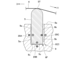
- FIG. 2 is an enlarged sectional view schematically showing main parts of the stringed instrument of FIG. 1.
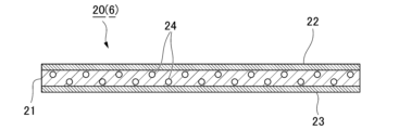
- FIG. FIG. 1 is a cross-sectional view schematically showing a pickup according to a first embodiment of the present invention.
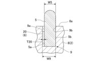
- FIG. 3 is an enlarged sectional view showing a state in which the tension of the string is not acting on the saddle in the first embodiment of the present invention.
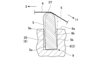
- FIG. 3 is an enlarged sectional view showing a state in which the tension of the string is applied to the saddle in the first embodiment of the present invention.
- FIG. 2 is an enlarged cross-sectional view showing main parts of a stringed instrument according to a second embodiment of the present invention.
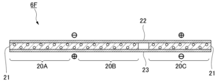
- FIG. 3 is a cross-sectional view schematically showing a pickup according to a second embodiment of the present invention.
- 7 is an enlarged cross-sectional view showing a state in which the tension of the string is applied to the saddle from the state shown in FIG. 6.
- FIG. 7 is an enlarged cross-sectional view of a main part of a stringed instrument according to a third embodiment of the present invention, showing a state in which the tension of the string is not acting on the saddle.
- FIG. 7 is an enlarged cross-sectional view of a main part of a stringed instrument according to a third embodiment of the present invention, showing a state in which the tension of the string is applied to the saddle.
- the stringed instrument 1 of the first embodiment is a guitar, and includes a musical instrument body 2, a neck 3, strings 4, a saddle 5, and a pickup 6.
- the musical instrument main body 2 includes a body 7 and a bridge 8 provided on the surface of the body 7.
- the neck 3 extends in one direction from the body 7 of the musical instrument body 2.
- the strings 4 are stretched across the instrument body 2 and the neck 3. Specifically, the first end of the string 4 is fixed to a string fixing part 11 provided on the bridge 8. The second end of the string 4 is wound up by a winder 12 provided at the tip of the neck 3.
- the saddle 5 is inserted into a groove 9 formed in the bridge 8 of the musical instrument body 2.
- the saddle 5 supports the strings 4 stretched across the musical instrument body 2 and the neck 3 while being inserted into the groove 9.
- the groove 9 is recessed from the surface 8a of the bridge 8.
- a portion of the saddle 5 inserted into the groove 9 protrudes from the surface 8a of the bridge 8.
- a tip portion 5T of the saddle 5 protruding from the surface 8a of the bridge 8 supports the string 4.
- the groove 9 of the bridge 8 and the saddle 5 inserted into the groove 9 are located between the neck 3 and the string fixing part 11 in the longitudinal direction of the string 4 (left-right direction in FIG. 2).
- the pickup 6 detects the vibrations of the strings 4 stretched across the instrument body 2 and the neck 3, and outputs a detection signal corresponding to the vibrations of the strings 4.
- the detection signal is an electrical signal and is used to output sound at the speaker.
- the pickup 6 includes a piezoelectric element 20 provided between the groove 9 of the musical instrument body 2 and the saddle 5. As shown in FIG. 3, the piezoelectric element 20 is formed into a plate shape and includes a porous layer 21 and electrode layers 22 and 23. The piezoelectric element 20 generates a voltage according to the expansion/contraction deformation of the porous layer 21 in the thickness direction, and outputs an electric signal (detection signal).
- the porous layer 21 is formed into a plate shape and can be elastically expanded and contracted in the thickness direction.
- the porous layer 21 has a plurality of pores 24 therein.
- the piezoelectric element 20 including the porous layer 21 has more expansion and contraction than a piezo element.
- the main component forming the porous layer 21 is preferably one that can be charged, such as polypropylene (PP), polyethylene (PE), polyethylene terephthalate (PET), polyvinyl chloride, polyolefin, fluorine resin, and the like.
- PP polypropylene
- PE polyethylene
- PET polyethylene terephthalate
- polyvinyl chloride polyolefin
- fluorine resin and the like.
- the "main component” is a component with the highest content, for example, a component with a content of 50% by mass or more.
- the porous layer 21 is generally formed by subjecting a plate-shaped body mainly composed of these synthetic resins to polarization treatment.
- Polarization treatment methods include, for example, applying a direct current or pulsed high voltage to inject charges, irradiating ionizing radiation such as gamma rays or electron beams to inject charges, and corona discharge treatment to inject charges. Examples include a method of injection.
- the electrode layers 22 and 23 are laminated on both sides of the porous layer 21 in the thickness direction. These two electrode layers 22 and 23 are each connected to a lead wire (not shown).
- the material forming the electrode layers 22 and 23 may be at least a conductive material, and may be, for example, various metals such as aluminum and silver, alloys of these metals, carbon, and the like.
- the method of laminating the electrode layers 22 and 23 on the porous layer 21 is not particularly limited, and examples include vapor deposition of aluminum, printing with carbon conductive ink, coating and drying of silver paste, and the like.
- the piezoelectric element 20 (first piezoelectric element) is arranged between the first inner surface 9a of the groove 9 and the first side surface 5a of the saddle 5, as shown in FIG.
- the first inner surface 9a of the groove 9 and the first side surface 5a of the saddle 5 face each other in the longitudinal direction of the string 4 supported by the saddle 5 when the saddle 5 is inserted into the groove 9. Further, the first inner side surface 9a of the groove 9 and the first side surface 5a of the saddle 5 are located on the neck 3 side in the longitudinal direction of the string 4. On the other hand, the second inner surface 9b of the groove 9, which faces the first inner surface 9a of the groove 9 in the longitudinal direction of the string 4, is located on the string fixing part 11 side in the longitudinal direction of the string 4. A second side surface 5b of the saddle 5 inserted into the groove 9 facing opposite to the first side surface 5a faces the second inner side surface 9b of the groove 9.
- the width W9 of the groove 9 from the first inner side surface 9a to the second inner side surface 9b is larger than the width W5 of the saddle 5 from the first side surface 5a to the second side surface 5b. Therefore, when the saddle 5 is inserted into the groove 9 such that the second side surface 5b of the saddle 5 contacts the second inner side surface 9b of the groove 9, the first inner surface 9a of the groove 9 and the first side surface of the saddle 5 A gap is formed between 5a and 5a.
- the piezoelectric element 20 is arranged between the first inner surface 9a and the first side surface 5a such that the thickness direction thereof faces in the arrangement direction of the first inner surface 9a of the groove 9 and the first side surface 5a of the saddle 5. Ru.
- the thickness T20 of the piezoelectric element 20 under no load is equal to the difference between the width W9 of the groove 9 and the width W5 of the saddle 5.
- the unloaded state of the piezoelectric element 20 means a state in which no external force is applied to the piezoelectric element 20 and the piezoelectric element 20 is not elastically expanded or contracted.
- the piezoelectric element 20 is not compressed in the thickness direction; It contacts the side surface 9a and the first side surface 5a.
- the saddle 5 can only move toward the first inner surface 9a of the groove 9, and cannot move away from the first inner surface 9a of the groove 9. Therefore, contact between the piezoelectric element 20 and the first inner surface 9a of the groove 9 and the first side surface 5a of the saddle 5 is maintained.
- the string 4 stretched across the string fixing part 11 of the musical instrument body 2 and the neck 3 is placed in the saddle 5 as shown in FIG.
- an external force based on the tension of the string 4 acts on the saddle 5.
- the strings 4 stretched across the string fixing portion 11 of the musical instrument body 2 and the neck 3 push the tip portion 5T of the saddle 5 toward the neck 3 side.
- the saddle 5 moves so as to be inclined toward the first inner surface 9a side of the groove 9, and as a result, the piezoelectric element 20 is compressed in its thickness direction.
- the thickness of the piezoelectric element 20 compressed as described above may be, for example, 50% or more of the thickness T20 of the piezoelectric element 20 under no load, but is more preferably, for example, 70% or more. That is, it is preferable that the amount of compression of the piezoelectric element 20 by external force be small. This is because the smaller the amount of compression of the piezoelectric element 20, the higher the sensitivity of the piezoelectric element 20.
- the vibrations of the strings 4 are transmitted to the piezoelectric element 20 via the saddle 5, and the porous layer 21 of the piezoelectric element 20 expands and contracts in its thickness direction.
- the piezoelectric element 20 outputs a detection signal (electric signal) according to the expansion/contraction deformation of the porous layer 21 .
- the piezoelectric element 20 has the porous layer 21.
- the piezoelectric element 20 has more expansion and contraction than a piezoelectric element without the porous layer 21 (for example, a conventional piezo element). Therefore, the unloaded thickness T20 of the piezoelectric element 20 does not have to be set with high accuracy with respect to the distance between the first side surface 5a of the saddle 5 and the first inner side surface 9a of the groove 9, as in the conventional case.
- the piezoelectric element 20 can be installed between the first side surface 5a of the saddle 5 and the first inner side surface 9a of the groove 9 without a gap.
- the piezoelectric element 20 can be easily installed between the first side surface 5a of the saddle 5 and the first inner side surface 9a of the groove 9. Furthermore, since the amount of expansion and contraction of the piezoelectric element 20 is large, even if the distance between the first side surface 5a of the saddle 5 and the first inner surface 9a of the groove 9 increases due to string vibration, the piezoelectric element 20 The one side surface 5a can be made difficult to separate from the first inner side surface 9a of the groove 9. This allows the piezoelectric element 20 installed between the saddle 5 and the groove 9 to expand and contract following the movement of the saddle 5, and as a result, the piezoelectric element 20 can correctly output a detection signal.
- the width W9 of the groove 9 from the first inner surface 9a to the second inner surface 9b is wider than the width W5 of the saddle 5 from the first side surface 5a to the second side surface 5b. It's also big. Further, the thickness T20 of the piezoelectric element 20 disposed between the first inner surface 9a of the groove 9 and the first side surface 5a of the saddle 5 under no load is equal to the width W9 of the groove 9 and the width W5 of the saddle 5. is equal to the difference between Therefore, even if the saddle 5 moves in the direction in which the first side surface 5a of the saddle 5 and the first inner surface 9a of the groove 9 are arranged, the piezoelectric element 20 I will never leave 9a.
- the piezoelectric element 20 allows the piezoelectric element 20 to expand and contract following the movement of the saddle 5 without bonding the piezoelectric element 20 to the saddle 5 or the groove 9, and as a result, the piezoelectric element 20 correctly outputs a detection signal. be able to. That is, it is possible to correctly output a detection signal from the pickup 6 in accordance with the movement of the saddle 5, while making it unnecessary to adhere the piezoelectric element 20 to the saddle 5 or the groove 9. Further, since it is not necessary to adhere the piezoelectric element 20 to the saddle 5 or the groove 9, the saddle 5 can be easily replaced or adjusted.
- the pickup 6 and the stringed instrument 1 of this embodiment as shown in FIG. It is arranged between the side surface 9a and the first side surface 5a of the saddle 5.
- the porous layer 21 of the piezoelectric element 20 is further compressed.
- the porous layer 21 of the piezoelectric element 20 expands. Thereby, the piezoelectric element 20 can detect the displacement of the saddle 5 toward and away from the first inner surface 9a of the groove 9.
- the thickness T20 of the piezoelectric element 20 under no load may be larger than, for example, the difference between the width W9 of the groove 9 and the width W5 of the saddle 5.
- the piezoelectric element 20 is placed between the first inner surface 9a and the first side surface 5a with the porous layer 21 compressed in its thickness direction. Even with such a configuration, the piezoelectric element 20 can detect the displacement of the saddle 5 toward and away from the first inner surface 9a of the groove 9, as in the first embodiment described above. I can do it.
- the piezoelectric element 20 may be bonded to, for example, the first side surface 5a of the saddle 5 and the first inner side surface 9a of the groove 9. In this case, when the saddle 5 is displaced away from the first inner surface 9a of the groove 9 in response to string vibration, even if the piezoelectric element 20 expands with respect to the no-load state, the piezoelectric element 20 can detect the displacement of the saddle 5.
- the saddle 5 inserted into the groove 9 of the bridge 8 is stretched across the string fixing part 11 of the instrument body 2 and the neck 3. supports the string 4 that is The relationship between the width W9 of the groove 9 and the width W5 of the saddle 5 is the same as in the first embodiment (see FIG. 4).
- the pickup 6F of the second embodiment has three piezoelectric elements 20A, 20B, and 20C.
- the three piezoelectric elements 20A, 20B, and 20C include a first piezoelectric element 20A, a second piezoelectric element 20B, and a third piezoelectric element 20C.
- each piezoelectric element 20A, 20B, 20C has a porous layer 21 and electrode layers 22, 23 similar to the first embodiment.
- the first piezoelectric element 20A is arranged between the first inner surface 9a of the groove 9 and the first side surface 5a of the saddle 5, similarly to the piezoelectric element 20 of the first embodiment.
- the thickness direction of the first piezoelectric element 20A is oriented in the direction in which the first inner surface 9a of the groove 9 and the first side surface 5a of the saddle 5 are arranged.
- the second piezoelectric element 20B is arranged between the bottom surface 9c of the groove 9 and the lower surface 5c of the saddle 5.
- the thickness direction of the second piezoelectric element 20B is oriented in the direction in which the bottom surface 9c of the groove 9 and the lower surface 5c of the saddle 5 are arranged.
- the bottom surface 9c of the groove 9 and the lower surface 5c of the saddle 5 are aligned in the insertion/removal direction of the saddle 5 with respect to the groove 9 (vertical direction in FIG. 6).
- the third piezoelectric element 20C is arranged between the second inner side surface 9b of the groove 9 and the second side surface 5b of the saddle 5.
- the thickness direction of the third piezoelectric element 20C is oriented in the direction in which the second inner side surface 9b of the groove 9 and the second side surface 5b of the saddle 5 are arranged.
- the thickness direction of the third piezoelectric element 20C may completely match the thickness direction of the first piezoelectric element 20A, or may be slightly shifted from the thickness direction of the first piezoelectric element 20A.
- the porous layers 21 (see FIG. 7) of the first piezoelectric element 20A and the third piezoelectric element 20C are It is good if it is compressed in the thickness direction.
- the degree to which the first piezoelectric element 20A and the third piezoelectric element 20C are compressed is preferably set so as to satisfy the following three conditions.
- the first condition is that the first piezoelectric element 20A and the third piezoelectric element 20C are not compressed to the maximum extent in a state where no external force such as the tension of the string 4 is acting on the saddle 5.
- the second condition is that even when the saddle 5 is brought close to the first inner surface 9a of the groove 9 and the first piezoelectric element 20A is compressed to the maximum, the third piezoelectric element 20C and the second inner surface 9b of the groove 9 are and that contact with the second side surface 5b of the saddle 5 is maintained.
- the third condition is that even when the saddle 5 is brought close to the second inner surface 9b of the groove 9 and the second piezoelectric element 20B is compressed to the maximum, the first piezoelectric element 20A and the first inner surface 9a of the groove 9 are and that contact with the first side surface 5a of the saddle 5 is maintained.
- the porous layer 21 of the second piezoelectric element 20B disposed between the groove 9 and the saddle 5 is arranged so that the string 4 stretched over at least the string fixing part 11 of the musical instrument body 2 and the neck 3 is connected to the tip portion 5T of the saddle 5. It is sufficient that the saddle 5 is compressed in the thickness direction of the porous layer 21 by the force received from the string 4 while being supported by the porous layer 21 . That is, in a state where no external force is acting on the saddle 5, the porous layer 21 of the second piezoelectric element 20B does not need to be compressed.
- the polarization direction of the porous layer 21 in the third piezoelectric element 20C is opposite to the polarization direction of the porous layer 21 in the first piezoelectric element 20A. . Further, the polarization direction of the porous layer 21 in the second piezoelectric element 20B is the same as the polarization direction of the porous layer in the first piezoelectric element 20A.
- the groove 9 side is the positive electrode, and the saddle 5 side is the negative electrode.
- the groove 9 side is the negative electrode
- the saddle 5 side is the positive electrode. Note that when the porous layer 21 is compressed in its thickness direction, a current flows through the porous layer 21 from the positive electrode to the negative electrode. Furthermore, when the porous layer 21 expands in its thickness direction, a current flows from the negative electrode to the positive electrode.
- the first piezoelectric element 20A, the second piezoelectric element 20B, and the third piezoelectric element 20C are integrally formed.
- the porous layers 21 of the first piezoelectric element 20A and the second piezoelectric element 20B having the same polarization direction are integrally formed.
- the porous layer 21 of the third piezoelectric element 20C whose polarization direction is different from that of the first and second piezoelectric elements 20A and 20B is formed separately from the porous layer 21 of the first and second piezoelectric elements 20A and 20B. There is.
- the first and second piezoelectric elements 20A, 20B and the third piezoelectric element 20C are integrally formed by two electrode layers 22, 23 laminated on both sides of the porous layer 21.
- the first electrode layer 22 is connected to the negative electrode of the porous layer 21 of the first and second piezoelectric elements 20A and 20B and the positive electrode of the third piezoelectric element 20C.
- the second electrode layer 23 is connected to the positive electrode of the porous layer 21 of the first and second piezoelectric elements 20A and 20B and the negative electrode of the third piezoelectric element 20C.
- the same effects as those of the first embodiment are achieved. Furthermore, in the pickup 6F and the stringed instrument of the second embodiment, the polarization direction of the porous layer 21 in the third piezoelectric element 20C is opposite to the polarization direction of the porous layer 21 in the first piezoelectric element 20A. For this reason, the electrode layers 22 and 23 provided on both sides of the porous layer 21 of the first piezoelectric element 20A and the electrode layers 22 and 23 provided on both sides of the porous layer 21 of the third piezoelectric element 20C are integrally formed.
- the detection signal output from the first piezoelectric element 20A and the detection signal output from the third piezoelectric element 20C can be prevented from canceling each other out. Further, according to the movement of the saddle 5, the detection signals output from the first piezoelectric element 20A and the third piezoelectric element 20C are added together. This point will be explained below.
- the saddle 5 vibrates in the longitudinal direction of the string 4 (the direction in which the first inner surface 9a and the second inner surface 9b of the groove 9 are arranged).
- the saddle 5 vibrates in this way, as shown in FIG. 8, when the first piezoelectric element 20A is compressed, the third piezoelectric element 20C is expanded. Furthermore, when the first piezoelectric element 20A expands, the third piezoelectric element 20C compresses.
- the first electrode layer 22 is connected to the negative electrode of the porous layer 21 of the first piezoelectric element 20A and the positive electrode of the third piezoelectric element 20C.
- the second electrode layer 23 is connected to the positive electrode of the porous layer 21 of the first piezoelectric element 20A and the negative electrode of the third piezoelectric element 20C. Therefore, when the first piezoelectric element 20A is compressed and the third piezoelectric element 20C is expanded, a current flows from the second electrode layer 23 to the first electrode layer 22 in both the first and third piezoelectric elements 20A and 20C. flows. Further, when the first piezoelectric element 20A is expanded and the third piezoelectric element 20C is compressed, a current flows from the first electrode layer 22 to the second electrode layer 23 in both the first and third piezoelectric elements 20A and 20C. .
- the detection signals output from the first piezoelectric element 20A and the third piezoelectric element 20C are added together.
- the detection signals output from the first and third piezoelectric elements 20A and 20C it is possible to further increase the S/N ratio of the detection signals output from the piezoelectric element 20 as the saddle 5 moves. .
- the polarization direction of the porous layer 21 in the second piezoelectric element 20B is the same as the polarization direction of the porous layer 21 in the first piezoelectric element 20A. Therefore, the detection signals output from the first and second piezoelectric elements 20A and 20B as the first and second piezoelectric elements 20A and 20B are compressed can be added together. This point will be explained below.
- the strings 4 When playing a stringed instrument, for example, when the strings 4 are pressed against the neck 3 with fingers, the strings 4 are pulled toward the neck 3. At this time, as shown in FIG. 8, the saddle 5 receives the force from the string 4 and moves toward the first inner surface 9a and bottom surface 9c of the groove 9. As a result, the first and second piezoelectric elements 20A and 20B located between the groove 9 and the first side surface 5a and lower surface 5c of the saddle 5 are compressed together.
- the first and second piezoelectric elements 20A and 20B can be added together.
- the detection signals output from 20A and 20B it is possible to further increase the S/N ratio of the detection signal output from the piezoelectric element 20 as the saddle 5 moves. .
- the first piezoelectric element 20A, the second piezoelectric element 20B, and the third piezoelectric element 20C are integrally formed. Therefore, compared to the case where these three piezoelectric elements 20A, 20B, and 20C are formed separately, the pickup 6F including these three piezoelectric elements 20 can be easily installed between the groove 9 and the saddle 5. be able to.
- the saddle 5 is inserted into the groove 9 of the bridge 8, as in the first embodiment.
- the saddle 5 supports the strings 4 stretched across the string fixing part 11 of the musical instrument body 2 and the neck 3.
- the relationship between the width W9 of the groove 9 and the width W5 of the saddle 5 is the same as in the first embodiment.
- a pickup 6G of the third embodiment includes a piezoelectric element 20 (first piezoelectric element) similar to that of the first embodiment. Further, the piezoelectric element 20 is arranged such that the first inner surface 9a of the groove 9 and the first side surface 5a of the saddle 5 are arranged so that the thickness direction thereof is oriented in the arrangement direction of the first inner surface 9a of the groove 9 and the first side surface 5a of the saddle 5. It is arranged between the side surface 5a and the side surface 5a.
- the first inner surface 9a of the groove 9 and the first side surface 5a of the saddle 5 are located on the string fixing part 11 side in the longitudinal direction of the string 4.
- the second inner side surface 9b of the groove 9 and the second side surface 5b of the saddle 5 are located on the neck 3 side in the longitudinal direction of the string 4.
- the thickness T20 of the piezoelectric element 20 under no load is smaller than the difference between the width W9 of the groove 9 and the width W5 of the saddle 5.
- the piezoelectric element 20 is then bonded to the first inner surface 9a of the groove 9 and the first side surface 5a of the saddle 5. Therefore, as shown in FIG. It can move in the direction toward the first inner surface 9a and in the direction away from the first inner surface 9a. By moving the saddle 5 in this manner, the piezoelectric element 20 expands and contracts in its thickness direction.
- the string 4 stretched across the string fixing part 11 of the musical instrument body 2 and the neck 3 is attached to the saddle 5, as shown in FIG.
- the front end portion 5T of the saddle 5 is pushed toward the neck 3 by the tension of the string 4.
- the saddle 5 moves so as to be inclined toward the second inner side surface 9b of the groove 9, and the first side surface 5a of the saddle 5 separates from the first inner side surface 9a of the groove 9.
- the piezoelectric element 20 is elongated in its thickness direction.
- the thickness of the piezoelectric element 20 stretched as described above may be, for example, 150% or less of the thickness T20 of the piezoelectric element 20 under no load, but is more preferably, for example, 130% or less. That is, it is preferable that the amount of expansion of the piezoelectric element 20 due to external force is small. This is because the smaller the amount of expansion of the piezoelectric element 20, the higher the sensitivity of the piezoelectric element 20.
- the vibrations of the strings 4 are transmitted to the piezoelectric element 20 via the saddle 5, and the porous layer 21 of the piezoelectric element 20 expands and contracts in its thickness direction.
- the piezoelectric element 20 outputs a detection signal (electric signal) according to the expansion/contraction deformation of the porous layer 21 .
- the piezoelectric element 20 in an expanded state expands and contracts with string vibration, the piezoelectric element 20 may be expanded or compressed relative to the state under no load.
- the piezoelectric element 20 has more expansion and contraction than a piezoelectric element without the porous layer 21 (for example, a conventional piezo element). Therefore, the unloaded thickness T20 of the piezoelectric element 20 does not have to be set with high accuracy with respect to the distance between the first side surface 5a of the saddle 5 and the first inner side surface 9a of the groove 9, as in the conventional case.
- the piezoelectric element 20 can be installed between the first side surface 5a of the saddle 5 and the first inner side surface 9a of the groove 9 without a gap.
- the piezoelectric element 20 by bonding the piezoelectric element 20 to the first side surface 5a of the saddle 5 and the first inner surface 9a of the groove 9, the piezoelectric element 20 can be easily attached to the first side surface 5a of the saddle 5 and the first inner surface 9a of the groove 9. It can be installed without any gap between the first inner surface 9a and the first inner surface 9a. Furthermore, since the amount of expansion and contraction of the piezoelectric element 20 is large, even if the distance between the first side surface 5a of the saddle 5 and the first inner surface 9a of the groove 9 increases due to string vibration, the piezoelectric element 20 It is possible to suppress or prevent the one side surface 5a from separating from the first inner side surface 9a of the groove 9. This allows the piezoelectric element 20 installed between the saddle 5 and the groove 9 to expand and contract following the movement of the saddle 5, and as a result, the piezoelectric element 20 can correctly output a detection signal.
- the pickup 6G and the stringed instrument of the third embodiment as shown in FIG. It is arranged between the side surface 9a and the first side surface 5a of the saddle 5.
- the porous layer 21 of the piezoelectric element 20 is compressed.
- the porous layer 21 of the piezoelectric element 20 further expands. Thereby, the piezoelectric element 20 can detect the displacement of the saddle 5 toward and away from the first inner surface 9a of the groove 9.
- the piezoelectric element 20 whose thickness T20 under no load is smaller than the difference between the width W9 of the groove 9 and the width W5 of the saddle 5 is located on the neck 3 side in the longitudinal direction of the string 4, for example. It may be arranged between the second inner side surface 9b of the groove 9 and the second side surface 5b of the saddle 5.
- the strings 4 are stretched across the string fixing part 11 of the musical instrument body 2 and the neck 3, and the strings 4 are supported by the tip portion 5T of the saddle 5, so that the tip portion 5T of the saddle 5 is caused by the tension of the string 4. It is pushed towards the neck 3 side.
- the piezoelectric element 20 is compressed between the groove 9 and the saddle 5. Therefore, the piezoelectric element 20 can be sandwiched between the second inner surface 9b of the groove 9 and the second side surface 5b of the saddle 5 without bonding the piezoelectric element 20 to the groove 9 or the saddle 5.
- the piezoelectric element 20 of the third embodiment whose thickness T20 under no load is smaller than the difference between the width W9 of the groove 9 and the width W5 of the saddle 5 is, for example, the three piezoelectric elements 20A, 20B, 20C (especially the first and third piezoelectric elements 20A and 20C).
- the pickup of the present invention is not limited to being applied to guitars, but can be applied to at least stringed instruments in which strings are supported by saddles inserted into grooves formed in the main body of the musical instrument.
Landscapes
- Physics & Mathematics (AREA)
- Engineering & Computer Science (AREA)
- Acoustics & Sound (AREA)
- Multimedia (AREA)
- Electrophonic Musical Instruments (AREA)
- Stringed Musical Instruments (AREA)
Abstract
La présente invention concerne un instrument à cordes qui comprend un corps d'instrument de musique 2, des cordes, un sillet 5 inséré dans une rainure 9 formée dans le corps d'instrument de musique 2 pour supporter les cordes et un lecteur phonographique 6 qui présente une couche poreuse étirable et déformable dans la direction de l'épaisseur et comprend un élément piézoélectrique 20 qui délivre un signal de détection en réponse à une déformation d'expansion et de contraction de la couche poreuse. L'élément piézoélectrique 20 est agencé entre une première surface latérale interne 9a de la rainure 9 et une première surface latérale 5a du sillet 5. La largeur W9 de la rainure 9, de la première surface latérale interne 9a à une seconde surface latérale interne 9b de la rainure 9, est supérieure à la largeur W5 du sillet 5 dans la direction d'agencement de la première surface latérale interne 9a et de la seconde surface latérale interne 9b. L'épaisseur T20 de l'élément piézoélectrique 20 dans la direction d'agencement dans un état non chargé est égale ou supérieure à la différence entre la largeur W9 de la rainure 9 et la largeur W5 du sillet 5.
Priority Applications (1)
| Application Number | Priority Date | Filing Date | Title |
|---|---|---|---|
| US18/926,294 US20250046273A1 (en) | 2022-04-26 | 2024-10-24 | String instrument and pickup |
Applications Claiming Priority (2)
| Application Number | Priority Date | Filing Date | Title |
|---|---|---|---|
| JP2022-072078 | 2022-04-26 | ||
| JP2022072078A JP7790265B2 (ja) | 2022-04-26 | 2022-04-26 | 弦楽器及びピックアップ |
Related Child Applications (1)
| Application Number | Title | Priority Date | Filing Date |
|---|---|---|---|
| US18/926,294 Continuation US20250046273A1 (en) | 2022-04-26 | 2024-10-24 | String instrument and pickup |
Publications (1)
| Publication Number | Publication Date |
|---|---|
| WO2023210375A1 true WO2023210375A1 (fr) | 2023-11-02 |
Family
ID=88518445
Family Applications (1)
| Application Number | Title | Priority Date | Filing Date |
|---|---|---|---|
| PCT/JP2023/014896 Ceased WO2023210375A1 (fr) | 2022-04-26 | 2023-04-12 | Instrument à cordes et lecteur phonographique |
Country Status (3)
| Country | Link |
|---|---|
| US (1) | US20250046273A1 (fr) |
| JP (1) | JP7790265B2 (fr) |
| WO (1) | WO2023210375A1 (fr) |
Citations (4)
| Publication number | Priority date | Publication date | Assignee | Title |
|---|---|---|---|---|
| JP2003345360A (ja) * | 2002-05-22 | 2003-12-03 | Yamaha Corp | 振動部材、振動検出装置、駒および弦楽器 |
| JP2006030406A (ja) * | 2004-07-13 | 2006-02-02 | Yamaha Corp | ピックアップ付き駒および弦楽器 |
| JP2007033806A (ja) * | 2005-07-26 | 2007-02-08 | Tadayoshi Furukawa | 弦楽器 |
| JP2019165846A (ja) * | 2018-03-22 | 2019-10-03 | ヤマハ株式会社 | 振動検出センサーユニット及びピックアップ |
-
2022
- 2022-04-26 JP JP2022072078A patent/JP7790265B2/ja active Active
-
2023
- 2023-04-12 WO PCT/JP2023/014896 patent/WO2023210375A1/fr not_active Ceased
-
2024
- 2024-10-24 US US18/926,294 patent/US20250046273A1/en active Pending
Patent Citations (4)
| Publication number | Priority date | Publication date | Assignee | Title |
|---|---|---|---|---|
| JP2003345360A (ja) * | 2002-05-22 | 2003-12-03 | Yamaha Corp | 振動部材、振動検出装置、駒および弦楽器 |
| JP2006030406A (ja) * | 2004-07-13 | 2006-02-02 | Yamaha Corp | ピックアップ付き駒および弦楽器 |
| JP2007033806A (ja) * | 2005-07-26 | 2007-02-08 | Tadayoshi Furukawa | 弦楽器 |
| JP2019165846A (ja) * | 2018-03-22 | 2019-10-03 | ヤマハ株式会社 | 振動検出センサーユニット及びピックアップ |
Also Published As
| Publication number | Publication date |
|---|---|
| US20250046273A1 (en) | 2025-02-06 |
| JP7790265B2 (ja) | 2025-12-23 |
| JP2023161630A (ja) | 2023-11-08 |
Similar Documents
| Publication | Publication Date | Title |
|---|---|---|
| US4750397A (en) | Electronic musical instrument with elastomeric strings and shielded bimorphic transducers | |
| US7199302B2 (en) | Transducer and method for forming a transducer | |
| US9117430B2 (en) | Electric stringed musical instrument and method of designing the same | |
| JP2017067763A (ja) | センサーユニット及び楽器 | |
| US7804018B2 (en) | Electric stringed musical instrument and pickup unit incorporated therein for converting vibrations to signal | |
| US9240174B2 (en) | Electric stringed musical instrument and method of designing the same | |
| US6336367B1 (en) | Vibration transducer unit | |
| US9544672B2 (en) | Condenser microphone | |
| JP3804637B2 (ja) | 弦楽器用駒および弦楽器 | |
| US6605771B1 (en) | Pickup assembly for musical instrument | |
| JP4363270B2 (ja) | ピックアップ付き駒および弦楽器 | |
| JP7790265B2 (ja) | 弦楽器及びピックアップ | |
| US7115803B2 (en) | Stringed instrument | |
| JP6730147B2 (ja) | 振動・音検出装置 | |
| US20220148548A1 (en) | Detection device, percussion instrument, and detection method | |
| US4916350A (en) | Sensor for detecting vibrations in a plane, particularly in a stringed musical instrument | |
| CN108140372A (zh) | 拾音器以及具有拾音器的弦乐器 | |
| JP2024024613A (ja) | 圧電振動装置及びスピーカ装置 | |
| JPS5841000A (ja) | 分極された固体誘電体を含むコンデンサ形電気音響変換器 | |
| JP2016109988A (ja) | 楽器用ピックアップ及び楽器 | |
| JP7766280B2 (ja) | 圧電振動装置 | |
| JP6044155B2 (ja) | ピックアップ機能付サドル | |
| WO2024106342A1 (fr) | Capteur piézoélectrique et instrument de musique | |
| CA1252652A (fr) | Instrument de musique a cordes | |
| JP6417846B2 (ja) | 弦楽器 |
Legal Events
| Date | Code | Title | Description |
|---|---|---|---|
| 121 | Ep: the epo has been informed by wipo that ep was designated in this application |
Ref document number: 23796119 Country of ref document: EP Kind code of ref document: A1 |
|
| NENP | Non-entry into the national phase |
Ref country code: DE |
|
| 122 | Ep: pct application non-entry in european phase |
Ref document number: 23796119 Country of ref document: EP Kind code of ref document: A1 |