WO2023209942A1 - 運転支援システム及び車両並びにコンピュータプログラムを記録した記録媒体 - Google Patents
運転支援システム及び車両並びにコンピュータプログラムを記録した記録媒体 Download PDFInfo
- Publication number
- WO2023209942A1 WO2023209942A1 PCT/JP2022/019264 JP2022019264W WO2023209942A1 WO 2023209942 A1 WO2023209942 A1 WO 2023209942A1 JP 2022019264 W JP2022019264 W JP 2022019264W WO 2023209942 A1 WO2023209942 A1 WO 2023209942A1
- Authority
- WO
- WIPO (PCT)
- Prior art keywords
- vehicle
- moving object
- moving
- mobile body
- driving support
- Prior art date
- Legal status (The legal status is an assumption and is not a legal conclusion. Google has not performed a legal analysis and makes no representation as to the accuracy of the status listed.)
- Ceased
Links
Images








Classifications
-
- G—PHYSICS
- G08—SIGNALLING
- G08G—TRAFFIC CONTROL SYSTEMS
- G08G1/00—Traffic control systems for road vehicles
- G08G1/16—Anti-collision systems
- G08G1/166—Anti-collision systems for active traffic, e.g. moving vehicles, pedestrians, bikes
-
- G—PHYSICS
- G08—SIGNALLING
- G08G—TRAFFIC CONTROL SYSTEMS
- G08G1/00—Traffic control systems for road vehicles
- G08G1/09—Arrangements for giving variable traffic instructions
-
- G—PHYSICS
- G08—SIGNALLING
- G08G—TRAFFIC CONTROL SYSTEMS
- G08G1/00—Traffic control systems for road vehicles
- G08G1/16—Anti-collision systems
Definitions
- the present disclosure relates to a driving support system, a vehicle, and a recording medium on which a computer program is recorded.
- vehicle-to-vehicle communication means or road-to-vehicle communication means to issue a warning to at least one of multiple vehicles entering an intersection, or to control the automatic driving of vehicles.
- Techniques for avoiding collisions between vehicles are known.
- any vehicle is not equipped with a vehicle-to-vehicle communication function, or if an intersection is not equipped with a road-to-vehicle communication function, it cannot be operated appropriately.
- Patent Document 1 describes a technology for avoiding accidents involving vehicles that are not equipped with a device such as a vehicle-to-vehicle communication means, and describes a technique for preventing accidents caused by collisions between vehicles that are not equipped with a device such as a vehicle-to-vehicle communication means.
- An information providing device is disclosed that provides information to the occupants of a vehicle of a moving object that does not have an inter-vehicle communication function and that may approach the vehicle on its path. Specifically, the own vehicle information, the moving object information including the position of the moving object, the traveling speed, and the traveling direction, and the time when this information was obtained are transmitted to the base station, and the own vehicle information determined by the base station is transmitted.
- An information providing device has been proposed that receives predictive information about moving objects existing within a predetermined range including the position and provides the information to the occupants of the own vehicle.
- a base station predicts the probability of the presence of a mobile body at a predetermined position based on the elapsed time since the mobile body was detected, regarding the operation of a mobile body without a vehicle-to-vehicle communication function. Predict the probability of the presence of a moving object at a given location based on the distance from the location where the moving object is detected to the given location, or predict the probability of the presence of a moving object at a given location based on road branch information in map data. do.
- the present disclosure has been made in view of the above-mentioned problems, and the purpose of the present disclosure is to improve the relationship between the first mobile object and the vehicle to be supported, which are in a situation where it is unable to transmit its own behavior data to the vehicle to be supported.
- the object of the present invention is to provide a driving support system and a vehicle capable of reducing the risk of a collision, as well as a recording medium on which a computer program is recorded.
- a driving support system that supports driving of a vehicle
- the driving support system comprising one or more processors and one or more processors communicatively connected to the one or more processors.
- one or more memories, and the one or more processors are configured to store a first action that is action data of the first moving object detected by an environment recognition device provided in a predetermined first moving object.
- the data is acquired from the environment recognition device directly or via an external server, and is sent to a second moving object that is on the planned travel route of the first moving object and which is a vehicle to be supported, directly or via an external server.
- a collision between the first moving object and the vehicle to be supported is determined based on the first action data of the first moving object obtained before the first time and the second action data obtained from the communication means of the second moving object.
- a predictive driving assistance system is provided.
- a vehicle equipped with a driving support device that supports driving of the vehicle wherein the driving support device is connected to a vehicle other than a predetermined first moving object.
- First behavior data which is behavior data of the first mobile body detected by the provided environment recognition device, is acquired directly from the environment recognition device or via an external server, and the first behavior data is the behavior data of the first mobile body that is present on the planned travel route of the first mobile body.
- second behavior data that is the behavior data of a second mobile body that has a communication means to transmit its own behavior data to the vehicle to be supported, directly or via an external server.
- a vehicle that predicts a collision between the first mobile object and the vehicle to be supported based on the second behavior data.
- a recording medium that records a computer program applied to a driving support system that supports driving of a vehicle, the recording medium having one or more processors.
- the first behavior data which is the behavior data of the first mobile body detected by the environment recognition device provided in a predetermined first mobile body, is acquired directly from the environment recognition device or via an external server.
- a second mobile body existing on the planned travel route of the first mobile body, the second mobile body having a communication means for transmitting its own behavior data to the vehicle to be supported, directly or via an external server.
- a computer program that executes a process including predicting a collision between the first mobile body and a vehicle to be supported based on the behavior data and the second behavior data acquired from the communication means of the second mobile body.
- a recorded recording medium is provided.
- FIG. 1 is a schematic diagram showing the basic configuration of a driving support system according to a first embodiment of the present disclosure. It is a block diagram showing an example of composition of an environment recognition device (road camera) of a driving support system concerning the same embodiment. It is a flowchart which shows the processing operation by the environment recognition device (road camera) of the driving support system concerning the same embodiment. It is a block diagram showing an example of composition of a portable terminal of a driving support system concerning the same embodiment. It is a flowchart which shows the processing operation by the portable terminal of the driving support system based on the same embodiment. It is a block diagram showing an example of composition of a management server of a driving support system concerning the same embodiment.
- FIG. 2 is a schematic diagram showing a configuration example of a vehicle to be supported by the driving support system of the same embodiment. It is a block diagram showing an example of composition of a driving support device of a driving support system concerning the same embodiment. It is a flowchart which shows the main routine of the processing operation by the driving support device of the driving support system based on the same embodiment. It is a flowchart which shows the collision prediction process by the driving support device of the driving support system based on the same embodiment. It is a flowchart which shows the collision prediction process by the driving support device of the driving support system based on the same embodiment.
- FIG. 2 is a block diagram illustrating a configuration example of a mobile terminal of a driving support system according to a second embodiment of the present disclosure.
- the "other vehicle” is the "first moving object”
- the “pedestrian” is the “second moving object”
- the “mobile terminal” is the "behavior of the second moving object”.
- An example will be explained in which the "road camera” is the “environment recognition device”. However, this does not limit each component.
- FIG. 1 is an explanatory diagram showing an example of the basic configuration of a driving support system 100.
- the driving support system 100 includes a driving support device 50 installed in a vehicle 1 to be supported, a road camera 150 installed on the road, a mobile terminal 130 carried by a pedestrian H, and a management server 110. .
- a driving support device 50 installed in a vehicle 1 to be supported
- a road camera 150 installed on the road
- a mobile terminal 130 carried by a pedestrian H
- a management server 110 a management server 110.
- one driving support device 50, one road camera 150, one mobile terminal 130, and one management server 110 are illustrated, but a plurality of each may be provided.
- the driving support device 50, the road camera 150, and the mobile terminal 130 are each communicably connected to the management server 110 via one or more communication networks 105.
- the driving support device 50 and the mobile terminal 130 are connected to the management server 110 via a mobile communication network.
- the road camera 150 may be connected to the management server 110 via a mobile communication network, or may be connected to the management server 110 via a wired communication network or a dedicated line.
- the road camera 150 is one aspect of an environment recognition device, and is installed on the road, generates image data of a photographed range in a predetermined processing cycle, and executes object recognition processing by performing image processing on the photographed image.
- the environment recognition device is not limited to the road camera 150, and may be a device capable of recognizing objects such as LiDAR, radar sensor, ultrasonic camera, etc. fixed at a predetermined position. It may also be an object recognition system using a camera mounted on the body, LiDAR, or the like.
- the road camera 150 detects moving objects such as vehicles, bicycles, and pedestrians every predetermined processing cycle, and also detects the moving direction and speed of the moving object based on the temporal change in the position of the detected moving object. Obtain by calculation.
- the road camera 150 transmits information on the detected moving object to the management server 110 in a predetermined processing cycle, along with information on the moving direction and speed, and information on the installation position and photographing direction of the road camera 150 on the map data. do.
- Information on the installation position of the road camera 150 is recorded in advance as longitude and latitude information on map data, for example.
- the information on the shooting direction of the road camera 150 may be recorded, for example, as a vector value in a coordinate system with longitude and latitude as xy axes, and is recorded as information on the orientation with respect to the road on which the road camera 150 is installed. may have been done.
- information on the position, moving direction, and moving speed of the moving object detected by the road camera 150 corresponds to first behavior data that is action data of the first moving object (other vehicle).
- the mobile terminal 130 is, for example, a smart phone, a smart watch, or other wearable device, and detects the position information of the mobile terminal 130 in a predetermined processing cycle, and also detects the movement of the mobile terminal 130 based on the change in the position of the mobile terminal 130 over time. The direction and moving speed are calculated.
- the position information of the mobile terminal 130 is acquired based on a satellite signal transmitted from a GNSS (Global Navigation Satellite System) satellite such as a GPS (Global Positioning System).
- the mobile terminal 130 transmits information on the position, moving direction, and moving speed of the mobile terminal 130 to the management server 110 in a predetermined processing cycle.
- the information on the position, moving direction, and moving speed of the mobile terminal 130 corresponds to second behavior data that is behavior data of the second moving object (pedestrian H) holding the mobile terminal 130.
- the management server 110 is an information processing device that is communicably connected to the road camera 150, the mobile terminal 130, and the driving support device 50 via the communication network 105 using, for example, cloud computing technology.
- the management server 110 receives captured images and information on the results of object recognition processing from the road camera 150 in a predetermined processing cycle.
- the information on the result of the object recognition process includes information on the detected first moving object and first behavior data of the first moving object.
- the management server 110 receives information on the position, movement direction, and movement speed of the mobile terminal 130 (second behavior data) from the mobile terminal 130 in a predetermined processing cycle.
- the management server 110 receives position information of the vehicle 1 from the driving support device 50 in a predetermined processing cycle.
- the management server 110 identifies a road camera 150 and a mobile terminal 130 that are present in a predetermined area according to the position of the vehicle 1, and transmits the first behavior data and second behavior data received from the road camera 150 and mobile terminal 130.
- the information is transmitted to the driving support device 50. That is, the management server 110 collects information from the road camera 150 and the mobile terminal 130, and also provides the vehicle 1 with information on other moving objects existing in the area around the traveling position of the vehicle 1.
- the driving support device 50 is installed in the vehicle 1 to be supported, detects position information of the vehicle 1 in a predetermined processing cycle, and transmits the detected position information to the management server 110.
- the position information of the vehicle 1 is acquired based on, for example, a satellite signal transmitted from a GNSS satellite such as GPS.
- the driving support device 50 also receives first behavior data and second behavior data from the management server 110 in a predetermined processing cycle, and predicts a collision between the vehicle 1 to be supported and another moving object (other vehicle). . When it is predicted that the vehicle 1 to be supported will collide with another moving object (other vehicle), the driving support device 50 executes processing to avoid the collision.
- FIG. 2 is a block diagram showing the functional configuration of the road camera 150.
- the road camera 150 includes an image generation unit 151 and an image processing device 160.
- the image generation unit 151 includes an image sensor such as a CCD (Charge Coupled Device) or a CMOS (Complementary Metal-Oxide Semiconductor), and generates image data of the photographing range.
- the image generation unit 151 generates image data every predetermined processing cycle and outputs it to the imaging processing device 160.
- the imaging processing device 160 includes a communication section 161, a processing section 163, and a storage section 169.
- the communication unit 161 is an interface for communicating with the management server 110 via the communication network 105.
- the processing unit 163 includes one or more CPUs (Central Processing Units) such as GPUs (Graphics Processing Units), and performs predetermined object recognition based on image data input from the image generation unit 151 every predetermined processing cycle. The process is executed and information on the recognition result is sent to the management server 110.
- CPUs Central Processing Units
- GPUs Graphics Processing Units
- the storage unit 169 includes one or more memories, and stores information on computer programs executed by the processing unit 163, various parameters used in calculation processing, and calculation results.
- the storage unit 169 includes magnetic media such as hard disks, floppy disks, and magnetic tapes, optical recording media such as CD-ROMs (Compact Disk Read Only Memory), DVDs (Digital Versatile Disks), and Blu-ray (registered trademark); Magnetic optical media such as optical disks, storage elements such as RAM (Random Access Memory) and ROM (Read Only Memory), flash memory such as USB (Universal Serial Bus) memory and SSD (Solid State Drive), and other records. It may be a medium.
- the processing section 163 includes an image processing section 165 and a communication control section 167.
- the functions of each of these parts are realized by execution of a computer program by a processor.
- the image processing unit 165 executes object recognition processing based on image data input from the image generation unit 151 in a predetermined processing cycle.
- the image processing unit 165 extracts feature points from the image data using techniques such as edge detection processing, and performs matching (also referred to as pattern matching processing) with data of feature points of various obstacles stored in advance. , executes processing to recognize objects existing in the shooting range.
- the road camera 150 mainly performs processing for recognizing moving objects. Typically, other vehicles, pedestrians, and bicycles are recognized as moving objects.
- the image processing unit 165 also obtains information regarding the moving speed and moving direction of the recognized moving object. For example, the image processing unit 165 can calculate the moving speed and moving direction of the moving object based on temporal changes in the position and size of the moving object in image data input every predetermined processing cycle.
- the method of determining the speed and moving direction of the recognized moving object through image processing is not particularly limited, and may be performed using conventionally known techniques.
- the communication control unit 167 transmits information on the type of moving body determined by the image processing unit 165 and information on the moving speed and direction of the moving body to the management server 110. At this time, the communication control unit 167 also transmits information regarding the installation position and photographing direction of the road camera 150 to the management server 110. When the management server 110 stores data on the installation position and shooting direction of each road camera 150, the road camera 150 transmits identification information for identifying each road camera 150 to the management server 110. It's okay.
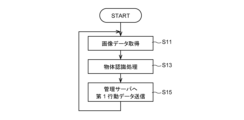
- FIG. 3 shows a flowchart of processing operations by the image processing device 160 of the road camera 150.
- the flowchart shown in FIG. 3 is repeatedly executed every predetermined processing cycle.
- the image processing unit 165 of the processing unit 163 acquires image data output from the image generation unit 151 (step S11).
- the image processing unit 165 executes object recognition processing based on the acquired image data (step S13).
- the image processing unit 165 extracts feature points from the image data using techniques such as edge detection processing, performs matching with data on feature points of various obstacles stored in advance, and determines the shooting range. Execute processing to recognize objects that exist in .
- the road camera 150 mainly performs processing for recognizing moving objects. Typically, other vehicles, pedestrians, and bicycles are recognized as moving objects.
- the image processing unit 165 also calculates the moving speed and moving direction of the recognized moving object. For example, the image processing unit 165 calculates the moving speed and moving direction of the moving object based on temporal changes in the position and size of the moving object in the image data input every predetermined processing cycle.
- the communication control unit 167 transmits information on the type of moving object determined by the image processing unit 165, and information on the moving speed and direction of the moving object to the management server 110 (step S15).
- the communication control unit 167 also transmits information regarding the installation position and photographing direction of the road camera 150 on the map data to the management server 110.
- the transmitted information corresponds to first behavior data of the moving object (first moving object).
- the imaging processing device 160 repeatedly executes the processing of steps S11 to S15 described above at every predetermined processing cycle.
- the first moving object detected by the road camera 150 is typically a vehicle, but it may also be a bicycle, a motorcycle, or any other object that can move at a predetermined speed. It's not something you can do.
- FIG. 4 is a block diagram showing the functional configuration of the mobile terminal 130.
- the mobile terminal 130 includes a communication section 131, a processing section 133, a storage section 139, and a GNSS sensor 141.
- the communication unit 131 is an interface for communicating with the management server 110 via the communication network 105.
- the GNSS sensor 141 receives satellite signals transmitted from GNSS satellites such as GPS.
- the satellite signal includes information representing the position of the mobile terminal 130 on the map data. For example, the location of the mobile terminal 130 is indicated as longitude and latitude data.
- the GNSS sensor 141 outputs the acquired position information of the mobile terminal 130 to the processing unit 133.
- the processing unit 133 includes one or more CPUs, acquires the position information of the mobile terminal 130 at every predetermined processing cycle, determines the moving speed and direction of the mobile terminal 130, and sends information on the calculation results to the management server 110. Send to.
- the storage unit 139 includes one or more memories, and stores information on computer programs executed by the processing unit 133, various parameters used in calculation processing, and calculation results.
- the storage unit 139 may be a storage element such as a RAM and a ROM, a flash memory such as an SSD, or other recording medium.
- the processing unit 133 includes a data processing unit 135 and a communication control unit 137. The functions of each of these parts are realized by execution of a computer program by a processor.
- the data processing unit 135 calculates the moving speed and moving direction of the mobile terminal 130 based on the position information input from the GNSS sensor 141 in a predetermined processing cycle. For example, the data processing unit 135 can calculate the moving speed and moving direction of the mobile terminal 130 based on temporal changes in positional information input every predetermined processing cycle.
- the communication control unit 137 transmits the position information of the mobile terminal 130 input from the GNSS sensor 141 and information on the moving speed and direction of the mobile terminal 130 determined by the data processing unit 135 to the management server 110.
- FIG. 5 shows a flowchart of processing operations by the mobile terminal 130.
- the flowchart shown in FIG. 5 is repeatedly executed every predetermined processing cycle.
- the data processing unit 135 of the processing unit 133 acquires position information input from the GNSS sensor 141 (step S21). Next, the data processing unit 135 calculates the moving direction and moving speed of the mobile terminal 130 based on the acquired position information (step S23). Specifically, the data processing unit 135 calculates the moving speed by differentiating the moving distance with respect to time based on the position information inputted every predetermined processing cycle. Furthermore, the data processing unit 135 determines a movement vector (movement direction) on the map data based on position information input at each predetermined processing cycle.
- the communication control unit 137 transmits the position information acquired from the GNSS sensor 141 and the calculated moving speed and moving direction information to the management server 110 (step S25).
- the transmitted information corresponds to second behavior data of the pedestrian (second moving object) H holding the mobile terminal 130.
- the mobile terminal 130 repeatedly executes the processes of steps S21 to S25 described above every predetermined processing cycle.
- the second moving object holding the mobile terminal 130 is not limited to a pedestrian, but may be a vehicle, a motorcycle, a bicycle, or any other object that moves at a predetermined moving speed.
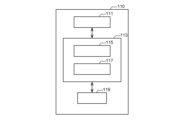
- FIG. 6 is a block diagram showing the functional configuration of the management server 110.
- the management server 110 includes a communication section 111, a processing section 113, and a storage section 119.
- the communication unit 111 is an interface for communicating with the road camera 150, the mobile terminal 130, and the driving support device 50 via the communication network 105.
- the processing unit 113 includes one or more CPUs, acquires information transmitted from the road camera 150, the mobile terminal 130, and the driving support device 50 every predetermined processing cycle, and acquires information transmitted from the road camera 150, the mobile terminal 130, and the driving support device 50, and performs processing according to the position of the driving support device 50.
- Information acquired from the road camera 150 and the mobile terminal 130 existing within the predetermined area is transmitted to the driving support device 50.
- the storage unit 119 includes one or more memories, and stores information on computer programs executed by the processing unit 113, various parameters used in calculation processing, and calculation results.
- the storage unit 119 includes magnetic media such as hard disks, floppy disks, and magnetic tapes, optical recording media such as CD-ROM, DVD, and Blu-ray (registered trademark), magnetic optical media such as floptical disks, RAM, and ROM. It may be a storage element such as, a flash memory such as a USB memory or an SSD, or other recording medium.
- the processing section 113 includes a data processing section 115 and a communication control section 117.
- the functions of each of these parts are realized by execution of a computer program by a processor.
- the data processing unit 115 identifies the position of the vehicle 1 to be supported on the map data based on the position information transmitted from the driving support device 50, and identifies the position of the vehicle 1 to be supported on the map data.
- Camera 150 and mobile terminal 130 are extracted.
- the communication control unit 117 transmits information on the type of moving object, moving speed, and moving direction received from the extracted road camera 150 to the driving support device 50 together with the position information on the map data of the road camera 150. Furthermore, the communication control unit 117 transmits the location information, moving speed, and moving direction information of the portable terminal 130 received from the extracted portable terminal 130 to the driving support device 50 .
- the data processing unit 115 determines the traveling direction of the vehicle 1 to be supported based on the position information transmitted from the driving support device 50, or obtains information on the traveling direction of the vehicle 1 to be supported from the driving support device 50. , road cameras 150 and mobile terminals 130 that exist on roads that lead to (intersect with) the road in the direction of travel may be extracted. As a result, it is possible to prevent information other than information for predicting a collision between the vehicle 1 to be supported and a moving object that may collide with the driving support device 50 from being sent to the driving support device 50, and the management server 110 and the driving support device 50 calculation processing loads can be reduced.
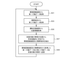
- FIG. 7 shows a flowchart of processing operations by the management server 110. The flowchart shown in FIG. 7 is repeatedly executed every predetermined processing cycle.
- the data processing unit 115 of the processing unit 113 acquires first behavior data transmitted from one or more environment recognition devices (road camera 150) (step S31).
- the data processing unit 115 acquires, together with the first behavior data, information on the type of the detected moving object and information on the installation position and photographing direction of the road camera 150 that is the transmission source. From this information, it is possible to understand which type of moving object is moving in which position, in which direction, and at what speed.
- the data processing unit 115 acquires the second behavior data transmitted from one or more mobile terminals 130 (step S33). From the second behavior data, it is possible to grasp which position, direction, and speed the moving object (pedestrian H) holding the mobile terminal 130 is moving.
- the data processing unit 115 acquires the position information of the vehicle 1 from the driving support device 50 mounted on the vehicle 1 to be supported (step S35).
- the position information of the vehicle 1 is information indicating the position of the vehicle 1 on the map data, and is indicated by, for example, longitude and latitude.
- the data processing unit 115 extracts the environment recognition device (road camera 150) and mobile terminal 130 that are present within a predetermined distance from the position of the vehicle 1 to be supported (step S37). For example, the data processing unit 115 extracts road cameras 150 and mobile terminals 130 that are present within an area within a predetermined radius from the position of the vehicle 1.
- the communication control unit 117 transmits the first behavior data and the second behavior data acquired from the extracted environment recognition device (road camera 150) and mobile terminal 130, respectively, to the vehicle 1 to be supported (step S39).
- the management server 110 repeatedly executes the processes of steps S31 to S39 described above every predetermined processing cycle.
- Driving support device (1-5-1. Vehicle)
- vehicle Before explaining the functional configuration of the driving support device 50 according to the embodiment of the present disclosure, an example of the overall configuration of the vehicle 1 to be supported equipped with the driving support device 50 will be described.
- FIG. 8 is a schematic diagram showing a configuration example of the vehicle 1 including the driving support device 50.
- the vehicle 1 shown in FIG. 8 uses the drive torque output from the drive power source 9 that generates the drive torque of the vehicle to a left front wheel 3LF, a right front wheel 3RF, a left rear wheel 3LR, and a right rear wheel 3RR (hereinafter, no particular distinction will be made).
- the vehicle is configured as a four-wheel drive vehicle that transmits power to the wheels (generally referred to as "wheels 3").
- the driving force source 9 may be an internal combustion engine such as a gasoline engine or a diesel engine, or may be a driving motor, or may include both an internal combustion engine and a driving motor.
- the vehicle 1 may be an electric vehicle equipped with two drive motors, for example, a front wheel drive motor and a rear wheel drive motor, and may be an electric vehicle equipped with a drive motor corresponding to each wheel 3. There may be.
- the vehicle 1 when the vehicle 1 is an electric vehicle or a hybrid electric vehicle, the vehicle 1 includes a secondary battery that stores power to be supplied to the drive motor, a motor that generates power to be charged to the battery, a fuel cell, etc. A generator will be installed.
- the vehicle 1 includes a driving force source 9, an electric steering device 15, and brake devices 17LF, 17RF, 17LR, and 17RR (hereinafter referred to as "brake device 17" if no particular distinction is required) as devices used for driving control of the vehicle 1. ).
- the driving force source 9 outputs a driving torque that is transmitted to the front wheel drive shaft 5F and the rear wheel drive shaft 5R via a transmission (not shown), a front wheel differential mechanism 7F, and a rear wheel differential mechanism 7R.
- the drive of the driving force source 9 and the transmission is controlled by a vehicle control section 41 that includes one or more electronic control units (ECUs).
- An electric steering device 15 is provided on the front wheel drive shaft 5F.
- the electric steering device 15 includes an electric motor and a gear mechanism (not shown), and is controlled by the vehicle control unit 41 to adjust the steering angles of the front left wheel 3LF and the front right wheel 3RF.
- the vehicle control unit 41 controls the electric steering device 15 based on the steering angle of the steering wheel 13 by the driver.
- the vehicle control unit 41 controls the electric steering device 15 based on the set travel trajectory.
- the brake devices 17LF, 17RF, 17LR, and 17RR apply braking force to the front, rear, left, and right drive wheels 3LF, 3RF, 3LR, and 3RR, respectively.
- the brake devices 17 are configured as, for example, hydraulic brake devices, and the hydraulic pressure supplied to each brake device 17 is controlled by the vehicle control unit 41 to generate a predetermined braking force.
- the brake device 17 is used in combination with regenerative braking by a drive motor.
- the vehicle control unit 41 controls driving of the driving force source 9 that outputs the driving torque of the vehicle 1 , the electric steering device 15 that controls the steering angle of the steering wheel or steered wheels, and the brake device 17 that controls the braking force of the vehicle 1 including one or more electronic control devices.
- the vehicle control unit 41 may have a function of controlling the drive of a transmission that changes the speed of the output output from the driving force source 9 and transmits it to the wheels 3.
- the vehicle control unit 41 is configured to be able to acquire information transmitted from the driving support device 50, and is configured to be able to execute automatic driving control of the vehicle 1.
- the vehicle 1 also includes a vehicle status sensor 35, a GNSS sensor 37, and an HMI (Human Machine Interface) 43.
- the vehicle condition sensor 35 includes at least one sensor that detects the operating condition and behavior of the vehicle 1.
- the vehicle condition sensor 35 includes, for example, at least one of a steering angle sensor, an accelerator position sensor, a brake stroke sensor, a brake pressure sensor, or an engine rotation speed sensor, and includes a steering angle of a steering wheel or steered wheels, an accelerator opening, and a brake.
- the operation state of the vehicle 1, such as the operation amount or engine rotation speed, is detected.
- vehicle condition sensor 35 includes, for example, at least one of a vehicle speed sensor, an acceleration sensor, or an angular velocity sensor, and detects vehicle behavior such as vehicle speed, longitudinal acceleration, lateral acceleration, or yaw rate. Vehicle condition sensor 35 transmits a sensor signal including detected information to driving support device 50.
- the GNSS sensor 37 receives satellite signals from GNSS satellites such as GPS.
- the GNSS sensor 37 outputs position information on the map data of the vehicle 1 included in the received satellite signal to the driving support device 50.
- the GNSS sensor 37 is not limited to a GPS sensor, and may be provided with an antenna that receives satellite signals from other satellite systems that specify the position of the vehicle 1.
- the HMI 43 is driven by the driving support device 50 and presents various information to the driver by means such as image display and audio output.
- the HMI 43 includes, for example, a display device provided in an instrument panel and a speaker provided in the vehicle.
- the display device may be a display device of a navigation system.
- the HMI 43 may include a HUD (head-up display) that displays on the front window superimposed on the scenery around the own vehicle 1.
- the driving support device 50 functions as a device that supports driving of a vehicle by having one or more processors such as CPUs execute computer programs.
- the computer program is a computer program for causing a processor to execute operations to be described later that should be executed by the driving support device 50.
- the computer program executed by the processor may be recorded on a recording medium that functions as a storage unit (memory) 61 provided in the driving assistance device 50, or may be recorded on a recording medium built in the driving assistance device 50 or a driving assistance device. 50 may be recorded on any recording medium that can be externally attached.
- Recording media for recording computer programs include magnetic media such as hard disks, floppy disks, and magnetic tapes, optical recording media such as CD-ROMs, DVDs, and Blu-ray (registered trademark), and magnetic optical media such as floptical disks. It may be a medium, a storage element such as RAM or ROM, a flash memory such as a USB memory or SSD, or another medium capable of storing a program.
- FIG. 9 is a block diagram showing the functional configuration of the driving support device 50.
- a vehicle condition sensor 35 and a GNSS sensor 37 are connected to the driving support device 50 directly or via a communication means such as a CAN (Controller Area Network) or a LIN (Local Internet). Further, a vehicle control unit 41 and an HMI 43 are connected to the driving support device 50.
- the driving support device 50 is not limited to an electronic control device installed in the vehicle 1, and may be a terminal device such as a smart phone or a wearable device.
- the driving support device 50 includes a communication section 51, a processing section 53, and a storage section 61.
- the communication unit 51 is an interface for communicating with the management server 110 via the communication network 105.
- the processing unit 53 includes one or more processors such as a CPU. A part or all of the processing unit 53 may be configured with something that can be updated, such as firmware, or may be a program module or the like that is executed by a command from a CPU or the like.
- the storage unit 61 is composed of one or more memories such as RAM or ROM, and is communicably connected to the processing unit 53. However, the number and types of storage units 61 are not particularly limited.
- the storage unit 61 stores information such as computer programs executed by the processing unit 53, various parameters used in calculation processing, detected data, and calculation results. Additionally, the storage unit 61 stores map data.
- the processing unit 53 includes a communication control unit 55, a collision risk determination unit 57, and a driving control unit 59.
- the functions of each of these parts are realized by execution of a computer program by a processor.
- some of the communication control section 55, collision risk determination section 57, and driving control section 59 may be configured by hardware such as an analog circuit.
- the communication control unit 55 transmits the position information of the vehicle 1 input from the GNSS sensor 37 to the management server 110 in a predetermined processing cycle.
- the communication control unit 55 may transmit information on the moving direction of the vehicle 1 to the management server 110 together with the position information of the vehicle 1.
- the collision risk determination unit 57 predicts a collision between the vehicle 1 to be supported and another moving object.
- the collision risk determination unit 57 receives the first action data of the first moving object detected by the road camera 150 and information about the position, moving speed, and moving direction of the mobile terminal 130, which is transmitted from the management server 110.
- a collision between the vehicle 1 and another moving object is predicted based on the information on the moving speed and course of the vehicle 1 (second behavior data) and the moving speed and course of the vehicle 1.
- the collision risk determination unit 57 determines whether the first behavior data of the first moving body detected by the road camera 150 is acquired after the first time when the first behavior data of the first moving body detected by the road camera 150 is acquired before the first time.
- the collision risk determination unit 57 determines whether the vehicle 1 and the second vehicle intersect based on the time difference between the estimated time when the first mobile object intersects with the path of the vehicle 1 to be supported and the estimated time when the vehicle 1 passes the intersection position. 1. Predict a collision with a moving object. Specific processing by the collision risk determination unit 57 will be explained in detail later.
- the driving control unit 59 sets driving conditions for the vehicle 1 to reduce the risk of collision when the collision risk determination unit 57 predicts that the vehicle 1 and the first moving object will collide.
- the driving conditions include, for example, a target deceleration condition for decelerating the vehicle 1.
- the driving conditions may include a target steering angular velocity condition for changing the travel trajectory of the vehicle 1 in addition to the target deceleration.
- the driving control unit 59 transmits information on the set driving conditions to the vehicle control unit 41.
- the vehicle control unit 41 controls traveling of the vehicle 1 based on the acquired driving conditions.
- the operation control unit 59 may set the target deceleration or target steering angular velocity so as not to exceed a preset upper limit value of deceleration or a preset upper limit value of steering angular velocity. Thereby, sudden steering or sudden deceleration of the host vehicle 1 can be prevented.
- FIG. 10 shows a flowchart of the main routine of processing operations by the driving support device 50.
- the flowchart shown in FIG. 10 is repeatedly executed every predetermined processing cycle.
- step S41 When the in-vehicle system including the driving support device 50 is activated (step S41), the communication control unit 55 of the processing unit 53 acquires the position information input from the GNSS sensor 37 (step S43), and uses the acquired position information. It is transmitted to the management server 110 (step S45).
- the collision risk determination unit 57 calculates the moving direction and moving speed of the vehicle 1 (step S47). Specifically, the collision risk determination unit 57 calculates the moving direction and moving speed of the vehicle 1 on the map data based on the temporal change in the position information input from the GNSS sensor 37 every predetermined processing cycle.
- the positional information input from the GNSS sensor 37 includes information on the direction of the vehicle 1, the moving direction of the vehicle 1 may be determined based on the information. Further, the moving speed of the vehicle 1 may be obtained from information detected by a vehicle speed sensor mounted on the vehicle 1.
- the collision risk determination unit 57 acquires the first behavior data and second behavior data transmitted from the management server 110 (step S49). Thereby, when the first moving object such as another vehicle is detected by the road camera 150, information about the installation position of the road camera 150 on the map data, and the moving direction and moving speed of the moving object is acquired. Furthermore, if there is a pedestrian H or the like (second moving object) holding the mobile terminal 130 within a predetermined distance from the vehicle 1, information on the position, moving direction, and moving speed of the second moving object on the map data is be obtained.
- the collision risk determination unit 57 performs a process of predicting a collision of the vehicle 1 (collision prediction) based on the information on the position, moving direction, and moving speed of the vehicle 1, and the acquired first behavior data and second behavior data. process) is executed (step S51). Specifically, the collision risk determination unit 57 determines whether the first behavior data of the first mobile body detected by the road camera 150 is acquired after the first time when the first behavior data of the first mobile body was acquired before the first time. A collision between the first moving object and the vehicle 1 to be supported is predicted based on the first action data and the second action data acquired from the mobile terminal 130 of the pedestrian H or the like (second moving object).
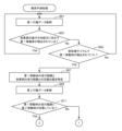
- the collision risk determination unit 57 refers to the first behavior data acquired from the management server 110 (step S61).
- the collision risk determination unit 57 determines whether or not a first moving object moving forward in the moving direction of the vehicle 1 is detected based on the first behavior data (step S63). Specifically, the collision risk determination unit 57 determines, based on the position and movement direction of the moving body indicated by the first action data, the road leading to the front in the movement direction of the road on which the vehicle 1 is traveling on the map data. It is determined whether a moving object moving forward in the moving direction of the vehicle 1 is detected.
- the collision risk determination unit 57 determines that the first moving object heading forward in the moving direction of the vehicle 1 in the previous processing cycle is detected. It is determined whether or not has been detected (step S65).
- the collision risk determination unit 57 continues monitoring the first behavior data.
- the collision risk determination unit 57 determines the traveling route of the first moving object and the vehicle 1's travel path.
- the intersection position with the travel route is specified (step S67). Specifically, the collision risk determination unit 57 specifies the traveling route of the first mobile body according to the moving direction of the first mobile body on the map data, and also specifies the traveling route of the vehicle 1 according to the moving direction of the vehicle 1. and identify the point where the two travel routes intersect.
- the collision risk determination unit 57 refers to the second behavior data acquired from the management server 110 (step S69). Next, the collision risk determination unit 57 determines whether the second mobile body holding the mobile terminal 130 is located on the travel route of the first mobile body based on the second behavior data (step S71). . Here, it is determined whether the position of the mobile terminal 130 included in the second action data exists on the road that is the travel route of the first mobile object.
- the collision risk determination unit 57 calculates the distance from the installation position of the road camera 150 to the intersection position, assuming that the moving speed of the first moving object passing through the installation position of the road camera 150 is maintained as it is.
- the required time is calculated by dividing by the moving speed and added to the first time to calculate the predicted arrival time.
- the collision risk determination unit 57 calculates the time when the vehicle 1 reaches the intersection position based on the information on the moving speed of the vehicle 1 (step S83). Specifically, the collision risk determination unit 57 calculates the required time by dividing the distance from the position of the vehicle 1 to the intersection position at the first time by the moving speed of the vehicle 1, and adds it to the first time to determine the predicted arrival time. Calculate.
- the collision risk determination unit 57 determines whether there is a possibility that the first moving object and the vehicle 1 will collide (step S85). Specifically, if the predicted arrival time of the first moving body calculated in step S81 and the predicted arrival time of the vehicle 1 calculated in step S83 are within a predetermined time difference, the collision risk determination unit 57 It is determined that there is a possibility that the moving object and vehicle 1 will collide.
- the predetermined time difference may be set to an arbitrary value in consideration of changes in the speed of the first moving body or vehicle 1, and so that the two vehicles do not feel danger to each other even if they do not collide.
- the collision risk determination unit 57 sets a collision avoidance process execution flag (step S87), and ends the collision prediction process. On the other hand, if there is no possibility that the first moving object and the vehicle 1 will collide (S85/No), the collision risk determination unit 57 ends the collision prediction process.
- step S71 if the second moving object is located on the travel route of the first moving object (S71/Yes), the collision risk determination unit 57 uses the first action data of the first moving object. Based on the second action data of the second moving object, the time at which the first moving object reaches the intersection position is calculated (step S91). Specifically, the collision risk determination unit 57 uses the first behavior data of the first moving object acquired before the first time when the first moving object was last detected by the road camera 150, and the first action data of the first moving object obtained after the first time. Based on the second action data of the two moving objects, the time at which the first moving object reaches the intersection position is calculated.
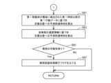
- FIG. 14 is a flowchart illustrating an example of a process for calculating the predicted arrival time of the first moving body to the intersection position when the second moving body is located on the travel route of the first moving body.
- the collision risk determination unit 57 determines whether the first mobile object is prevented from traveling by the second mobile object based on the second behavior data of the second mobile object after the first time when the first mobile object is detected by the road camera 150. It is determined whether or not it is inhibited (step S101). For example, the collision risk determination unit 57 determines when the second moving body enters the route that the first moving body passes, or when the second moving body moves in a direction that intersects the route that the first moving body passes. In this case, it is determined that the first moving object is obstructed by the second moving object.
- the collision risk determination unit 57 determines whether the second moving body is moving based on the moving speed and moving direction of the second moving body and the moving speed and moving direction of the first moving body detected by the road camera 150. , when it is predicted that the second moving object will enter the passage area of the first moving object at the same time as the predicted passage time of the first moving object, it may be determined that the first moving object is obstructed from traveling by the second moving object. .
- the predicted passing time of the first moving body at each point can be predicted based on the moving speed and elapsed time of the first moving body.
- the predicted route of the second moving object can be predicted based on the moving speed, moving direction, and travel time of the second moving object.
- the collision risk determination unit 57 determines that the first moving object is not detected by the road camera 150 without accelerating or decelerating. Assuming that the moving speed is maintained at the time when the moving speed was reached, the process advances to step S111. In this case, the collision risk determination unit 57 calculates the required time by dividing the distance from the position of the first moving object to the intersection position at the first time by the moving speed, and adds it to the first time to calculate the predicted arrival time. (Step S111).
- the collision risk determination unit 57 causes the first moving object to start decelerating at a predetermined deceleration, It is assumed that the vehicle is decelerated to a predetermined low running speed (step S105).
- the predetermined deceleration rate may be set according to the distance from the first moving body to the second moving body at the time of starting deceleration. In this case, the shorter the distance from the first moving body to the second moving body, the larger the deceleration is set.
- the predetermined low running speed may be set depending on the width of the road on which the first moving object runs. In this case, the smaller the road width, the smaller the low running speed is set.
- the deceleration and low running speed may be set according to the moving speed of the first moving body based on statistical data collected about general deceleration timing.
- the collision risk determination unit 57 determines whether the first moving object has overtaken the second moving object (step S107). Specifically, the collision risk determination unit 57 determines the moving speed when the first moving object was detected by the road camera 150, the deceleration and low running speed assumed in step S105, and the traveling speed at each moving speed. When the position of the first mobile body estimated based on time passes the position of the second mobile body specified as the position information of the mobile terminal 130 that changes from moment to moment, the first mobile body moves to the second mobile body. It is determined that the vehicle has overtaken the moving object.
- the collision risk determination unit 57 assumes that the first moving object continues to move in a decelerated state, and the first moving object crosses the intersection.
- a predicted arrival time at the location is calculated (step S111). Specifically, the collision risk determination unit 57 adjusts the movement speed from the distance from the position of the first moving object to the intersection position at the first time to the moving speed when the first moving object was detected by the road camera 150. The remaining distance obtained by subtracting the travel distance obtained over the time traveled at the speed is used to calculate the required time when traveling at the deceleration and low travel speed assumed in step S105. Then, the predicted arrival time is calculated by adding the sum of the time traveled at the movement speed before deceleration and the time required after the start of deceleration to the first time.
- the collision risk determination unit 57 determines that the first mobile body has passed the second mobile body after the second time when the first mobile body has overtaken the second mobile body. It is assumed that the vehicle accelerates and recovers to the moving speed before deceleration (step S109).
- the acceleration at this time may be a constant acceleration set in advance, or may be an arbitrary acceleration depending on the movement speed after recovery. Further, if information indicating a tendency of the acceleration of the first moving object is obtained from the first action data of the first moving object detected by the road camera 150, the acceleration may be set according to the information. .
- the collision risk determination unit 57 calculates a predicted arrival time at which the first moving object will reach the intersection position, assuming that the first moving object has decelerated and accelerated after the second time (step S111). Specifically, the collision risk determination unit 57 calculates the travel distance obtained by multiplying the travel speed at which the first moving object was detected by the road camera 150 by the time it has traveled at the travel speed since the first time. do. Further, the collision risk determination unit 57 calculates the deceleration and low running speed assumed in step S105, the time after the second time when the vehicle traveled at the acceleration assumed in step S109, and the distance traveled during that time.
- the collision risk determination unit 57 calculates, from the distance from the position of the first moving object to the intersection position at the first time, the distance traveled by the first moving object at the moving speed when it was detected by the road camera 150. , the time required for the remaining distance is calculated by subtracting the sum of the travel distance traveled from the start of deceleration to the time the travel speed recovers to the pre-deceleration travel speed, and then dividing the remaining distance by the travel speed after recovery. Then, calculate the sum of the time traveled at the speed before deceleration, the time required from the start of deceleration until the speed recovers to the speed before deceleration, and the time required to travel the remaining distance at the speed after recovery. The predicted arrival time is calculated by adding it to the first time.
- the collision risk determination unit 57 calculates the time at which the vehicle 1 will arrive at the intersection position based on the information on the moving speed of the vehicle 1. is calculated (step S93). Specifically, the collision risk determination unit 57 calculates the required time by dividing the distance from the position of the vehicle 1 to the intersection position at the first time by the moving speed of the vehicle 1, and adds it to the first time to determine the predicted arrival time. Calculate.
- the collision risk determining unit 57 determines whether or not there is a possibility that the first moving object and the vehicle 1 will collide (step S95), using the same procedure as step S85 described above. If there is a possibility that the first moving object and the vehicle 1 will collide (S95/Yes), the collision risk determination unit 57 sets a collision avoidance process execution flag (step S97), and ends the collision prediction process. On the other hand, if there is no possibility that the first moving object and the vehicle 1 will collide (S95/No), the collision risk determination unit 57 ends the collision prediction process.
- the driving control unit 59 executes the collision avoidance process (step S53). Specifically, the driving control unit 59 executes a process for avoiding a collision between the vehicle 1 and the first moving body when the collision avoidance process execution flag is set as a result of the collision prediction process. For example, the driving control unit 59 may avoid a collision between the vehicle 1 and the first moving body by decelerating the vehicle 1 and thereby delaying the time when the vehicle 1 reaches the intersection position. Alternatively, if the road on which the vehicle 1 is traveling is wide or has multiple lanes, instead of decelerating the vehicle 1, or in conjunction with decelerating the vehicle 1, the vehicle 1 and the first moving body may be avoided.
- the driving control section 59 sets an instruction value for deceleration and an instruction value for the steering angle of the vehicle 1, and transmits the instruction values to the vehicle control section 41.
- a predicted arrival time at which the first moving object will reach the intersection position is predicted, taking into consideration not only the moving speed of the first moving object but also the deceleration and acceleration due to the influence of the second moving object existing on the travel route of the first moving object. Thereby, the prediction accuracy of the collision between the vehicle 1 and the first moving body can be improved.
- FIGS. 15 to 18 are explanatory diagrams for explaining application examples of the driving support system 100 according to the present embodiment, in which the vehicle 1 to be supported and the other vehicle 90 as the first moving object are at the intersection C.
- An example of application is shown in a driving scene where the vehicle is driving toward a destination.
- FIG. 15 shows a situation where another vehicle 90 is located in the photographing range 153 of the road camera 150 as an environment recognition device and is recognized by the road camera 150.
- the time when the other vehicle 90 reaches the intersection C while maintaining the current speed of movement and the time when the vehicle 1 arrives at the intersection C overlap, and the other vehicle 90 and the vehicle 1 to be supported collide. It is assumed that there is a risk.
- a pedestrian H who is a second moving object and who owns a mobile terminal 130 .
- FIG. 16 shows the other vehicle 90 moving toward the intersection C and moving out of the photographing range 153 of the road camera 150.
- the pedestrian H is moving on the side of the road and is not in a situation where it will obstruct the travel of other vehicles 90.
- FIG. 17 shows a situation where a pedestrian H enters onto a route along which another vehicle 90 is traveling. The other vehicle 90 decelerates to avoid a collision with the pedestrian H.
- FIG. 18 shows a situation where the pedestrian H crosses in front of another vehicle 90, and then the other vehicle 90 overtakes the pedestrian H. The other vehicle 90 accelerates because the pedestrian H is no longer in front of it.
- the driving support device of the vehicle 1 to be supported uses the moving speed of the other vehicle 90 detected by the road camera 150 and the installation position of the road camera 150, without considering information about the pedestrian H.
- the predicted arrival time at which the other vehicle 90 will arrive at the intersection C is determined based on the distance from the intersection C to the intersection C.
- the predicted arrival time of the support target vehicle 1 to the intersection C and the predicted arrival time of the other vehicle 90 to the intersection C are within a predetermined time difference, and the driving support device detects the other vehicle 90 (see FIG. 18). It is predicted that the other vehicle 90a) indicated by the broken line will collide with the vehicle 1 to be supported. Therefore, even though the other vehicle 90 has not actually reached the intersection C, the driving support device decelerates the vehicle 1 to be supported or changes the route of the vehicle 1. , the driver and other occupants of the vehicle 1 to be supported will feel distrustful.
- the driving support device 50 assumes that the other vehicle 90 is decelerated in response to determining that the other vehicle 90 is obstructed by the pedestrian H, and further assumes that the other vehicle 90 is Assume that after overtaking person H, the vehicle recovers its moving speed to the speed before deceleration. Therefore, the predicted arrival time when the other vehicle 90 will arrive at the intersection C and the predicted arrival time when the support target vehicle 1 will arrive at the intersection C exceed a predetermined time difference, and the driving support device 50 will A collision with the target vehicle 1 is not predicted. Therefore, the driving support device 50 does not decelerate the vehicle 1 to be supported or change the route of the vehicle 1, and does not cause distrust in the driver or other occupants of the vehicle 1 to be supported. It can be prevented.
- the driving support device 50 is configured to detect a first mobile object detected by the road camera 150 provided on the first mobile object other than the first mobile object.
- the first behavior data is acquired via the management server 110, and the data is transmitted to the vehicle 1, which is a second mobile body existing on the planned travel route of the first mobile body and is the support target, via the management server 110.
- the second behavior data of the second mobile object having the mobile terminal 130 that transmits the behavior data is acquired.
- the driving support device 50 also stores the first behavior data of the first moving object acquired after the first time when the first moving object was last detected by the road camera 150 and before the first time, and the second moving object.
- a collision between the first mobile object and the vehicle 1 to be supported is predicted based on the second action data acquired from the mobile terminal 130 of.
- a collision between the first moving object and the vehicle 1 to be supported can be predicted by considering the deceleration and acceleration of the first moving object.
- the driving support device 50 predicts that the first moving object will decelerate when it is determined that the first moving object will be hindered from traveling by the second moving object. , estimate a change in the moving speed of the first moving object. Therefore, it is possible to predict a collision between the first moving body and the vehicle 1 to be supported, taking into consideration the fact that the time at which the first moving body reaches the intersection position is delayed by the second moving body.
- the driving support device 50 predicts that the second moving object will enter the passage area of the first moving object at the same time as the predicted passage time of the first moving object. In this case, it is determined that the movement of the first moving object is obstructed by the second moving object. As a result, it is possible to predict not only that the second moving object is present on the travel route of the first moving object, but also to specifically predict the situation in which the first moving object will decelerate, and to detect the situation between the first moving object and the vehicle to be supported. It is possible to predict collisions with
- the driving support device 50 causes the first mobile object to recover the speed before deceleration after the second time when it is estimated that the first mobile object has overtaken the second mobile object. Then, a collision between the first mobile object and the vehicle 1 to be supported is predicted. Therefore, a collision between the first moving object and the vehicle 1 to be supported can be predicted by taking into account the acceleration after the first moving object has overtaken the second moving object.
- a driving support system according to a second embodiment will be described.
- a second mobile body existing on the travel route of the first mobile body transmits sounds and noises around itself to the vehicle to be supported, either directly or via an external server.
- the device is configured to be able to transmit at least one of its own biometric information.
- the biometric information of the second moving object is the biometric information of a pedestrian or the biometric information of a person riding a moving object such as a bicycle.
- the support target vehicle estimates the position of the first mobile body using the second behavioral data and the surrounding sounds or biometric information of the second mobile body, and estimates the position of the first mobile body and the support target. Predict collisions with vehicles.
- the driving support system according to the second embodiment will be mainly described in terms of its differences from the driving support system according to the first embodiment.
- the basic configuration of the driving support system according to this embodiment may be configured similarly to the basic configuration of the driving support system according to the first embodiment shown in FIG.
- the functional configuration of the environment recognition device (road camera 150) may be the same as the environment recognition device of the driving support system according to the first embodiment.
- the mobile terminal 130 is equipped with a microphone array that collects surrounding sounds and a biosensor that detects biometric information of the second moving body, and is configured to be able to transmit the detected collected waveform and biometric information to the management server 110. may be the same as the mobile terminal 130 of the driving support system according to the first embodiment.
- the management server 110 is the same as the management server 110 of the driving support system according to the first embodiment, except that the management server 110 is configured to be able to acquire collected sound waves and biological information transmitted from the mobile terminal 130 and transmit them to the driving support device 50.
- the driving support device 50 is configured to provide support between the first mobile body and the support device based on the sounds and biological information around the second mobile body, as well as the first behavior data of the first mobile body and the second behavior data of the second mobile body. A collision with the target vehicle 1 is predicted.
- the mobile terminal 130 includes both a microphone array and a biosensor; however, it may include only either the microphone array or the biosensor.
- FIG. 19 is a block diagram showing the functional configuration of the mobile terminal 130A.
- the mobile terminal 130A includes a communication section 131, a processing section 133, a storage section 139, a GNSS sensor 141, a microphone array 143, and a biosensor 145.
- the functions of the communication unit 131, the storage unit 139, and the GNSS sensor 141 may be the same as those of the mobile terminal 130 of the driving support system according to the first embodiment.
- the microphone array 143 outputs the sounds surrounding the mobile terminal 130A as waveform data to the processing unit 133.
- the biosensor 145 may be a non-wearable or wearable sensor that detects the heartbeat or pulse of the second moving object, for example, but also has a function of detecting other biological information such as blood pressure or body temperature of the second moving object. It may be a sensor. Further, the biosensor 145 may be included in the main body of the mobile terminal 130A, or may be included in a wearable device communicably connected to the processing unit 133 of the mobile terminal 130A. In this case, the biosensor 145 can communicate with the processing unit 133 via wireless communication means such as Bluetooth (registered trademark), NFC (Near Field Communication), WiFi (wireless fidelity), and wireless LAN (Local Area Network). may be configured.
- wireless communication means such as Bluetooth (registered trademark), NFC (Near Field Communication), WiFi (wireless fidelity), and wireless LAN (Local Area Network).
- the processing unit 133 includes one or more CPUs, and acquires the position information of the mobile terminal 130A every predetermined processing cycle, and determines the moving speed and direction of the mobile terminal 130. Furthermore, the processing unit 133 acquires waveform data (collected sound waveform) of sounds around the mobile terminal 130A and biometric information of the second mobile object every predetermined processing cycle. Further, the processing unit 133 transmits the acquired information and information on the calculation results to the management server 110 for each predetermined processing cycle.
- the storage unit 139 includes one or more memories, and stores information on computer programs executed by the processing unit 133, various parameters used in calculation processing, and calculation results.
- the storage unit 139 may be a storage element such as a RAM and a ROM, a flash memory such as an SSD, or other recording medium.
- the processing unit 133 includes a data processing unit 136 and a communication control unit 137. The functions of each of these parts are realized by execution of a computer program by a processor.
- the data processing unit 136 calculates the moving speed and moving direction of the mobile terminal 130 based on the position information input from the GNSS sensor 141 in a predetermined processing cycle. For example, the data processing unit 135 can calculate the moving speed and moving direction of the mobile terminal 130 based on temporal changes in positional information input every predetermined processing cycle.
- the communication control unit 137 receives the position information of the mobile terminal 130 inputted from the GNSS sensor 141, the information on the moving speed and direction of the mobile terminal 130 determined by the data processing unit 135, the collected waveform, and the second mobile object.
- the biometric information is also transmitted to the management server 110.
- FIG. 20 shows a flowchart of processing operations performed by the mobile terminal 130A.
- the flowchart shown in FIG. 20 is repeatedly executed every predetermined processing cycle.
- the data processing unit 136 of the processing unit 133 acquires position information input from the GNSS sensor 141, waveform data input from the microphone array 143, and biological information input from the biosensor 145 (step S22). Next, the data processing unit 136 calculates the moving direction and moving speed of the mobile terminal 130 based on the acquired position information using the same procedure as step S23 described in the first embodiment (step S24).
- the communication control unit 137 transmits the position information acquired from the GNSS sensor 141, the calculated moving speed and moving direction information, the acquired collected sound waveform, and biological information to the management server 110 (step S26). .
- the mobile terminal 130A repeatedly executes the processes from step S22 to step S26 described above every predetermined processing cycle.
- the second moving object holding the mobile terminal 130 is not limited to a pedestrian, but may be a vehicle, a motorcycle, a bicycle, or any other object that moves at a predetermined moving speed.
- Driving support device The basic functional configuration of the driving support device in the driving support system according to the present embodiment and the configuration of the vehicle to which the driving support device can be applied are the functional configuration of the driving support device and the driving support device according to the first embodiment.
- the configuration may be similar to that of a typical vehicle.
- the processing operation of the driving support device of the driving support system according to this embodiment will be described below.
- the main routine of the processing operation by the driving support device 50 may be the same as the processing operation by the driving support device of the driving support system according to the first embodiment shown in FIG. Among these, the content of the process of predicting a collision between the first moving object and the vehicle 1 to be supported is different from that in the first embodiment, so below, FIGS. 11, 12, 21, and 22 will be referred to. Next, collision prediction processing by the driving support device 50 according to the present embodiment will be explained.
- the collision risk determination unit 57 executes the processes of each step S61 to step S71 described above according to the flowchart shown in FIG. Further, in step S71, if the second moving body is not located on the travel route of the first moving body (S71/No), the collision risk determination unit 57 performs each of the above-mentioned operations according to the flowchart shown in FIG. The processes from step S81 to step S87 are executed.
- step S71 if the second moving object is located on the travel route of the first moving object (S71/Yes), the collision risk determination unit 57 uses the first action data of the first moving object and the first action data of the first moving object.
- the time at which the first moving object reaches the intersection position is calculated based on the second action data, the collected sound waveform, and the biological information of the second moving object (step S92).
- the collision risk determination unit 57 uses the first behavior data of the first moving object acquired before the first time when the first moving object was last detected by the road camera 150, and the first action data of the first moving object obtained after the first time.
- the time at which the first moving object reaches the intersecting position is calculated based on the second action data, the collected sound waveform, and the biological information of the second moving object.
- FIG. 22 is a flowchart illustrating an example of a process for calculating the predicted arrival time of the first moving body to the intersection position when the second moving body is located on the travel route of the first moving body.
- the collision risk determination unit 57 estimates the position of the first moving object based on the acquired waveform data (collected sound waveform) of the surrounding sound of the second moving object (step S121). Specifically, based on the waveform data output from the microphone array 143, the collision risk determination unit 57 determines the situation in which the first moving object approaches the second moving object and the situation in which the first moving object moves away from the second moving object. Estimate.
- the collision risk determination unit 57 determines that when the sound around the second moving body is gradually increasing, the first moving body approaches the second moving body, and then the sound around the second moving body gradually increases. It may be determined that the first moving body is away from the second moving body when the first moving body is smaller than the second moving body.
- the collision risk determination unit 57 identifies the moving direction of the sound source based on the collected sound waveform, and determines whether the first moving object approaches or leaves. It's okay.
- the collision risk determination unit 57 estimates the position of the first moving body based on the acquired biometric information of the second moving body (step S123).
- the collision risk determination unit 57 monitors the biological information of the second moving object, and if the heart rate, pulse, blood pressure, response, etc. suddenly increases, the first moving object is within a predetermined range from the second moving object. It is determined that it is located.
- the value of the predetermined range may be set to any appropriate value in advance.
- the collision risk determination unit 57 calculates the predicted arrival time when the first mobile body will reach the intersection position with the vehicle 1 to be supported, taking into account the position of the first mobile body estimated in step S121 or step S123. Calculate (step S125). Specifically, the collision risk determination unit 57 calculates a value obtained by dividing the distance from the position of the first moving object to the intersection position at the first time by the moving speed when the first moving object was detected by the road camera 150. is the basic required time. Further, when it is estimated that the first moving object approaches the second moving object in step S121 or step S125, the collision risk determination unit 57 determines the first time based on the position information of the second moving object at that time. Find the distance from the position of the first moving body to the position of the second moving body.
- the collision risk determination unit 57 divides the calculated distance value by the time required from the first time to the time when the first moving object approaches the second moving object, so that the first moving object can move to the second moving object. Calculate the average movement speed to a position close to the body.
- the collision risk determination unit 57 calculates the remaining required time by dividing the remaining distance from the position where the first moving object approaches the second moving object to the intersection position by the average moving speed, and calculates the sum of the required times. A predicted arrival time at which the first moving object will arrive at the intersection position is calculated by adding it to the first time.
- the collision risk determination unit 57 calculates the predicted arrival time when the first moving body reaches the intersection position, and then performs the first movement A collision between the body and the vehicle 1 to be supported is predicted, and the collision prediction process is ended. Thereafter, according to the flowchart shown in FIG. 10, if a collision between the first mobile object and the vehicle 1 to be supported is predicted and the collision avoidance processing execution flag is set, the driving control is performed in step S53. The collision avoidance process is executed by the unit 59.
- the driving support device 50 is configured to operate the driving support device 50 on the first mobile object detected by the road camera 150 provided on the first mobile object other than the first mobile object.
- 1 behavior data is acquired via the management server 110, and is transmitted to the vehicle 1, which is a second moving object existing on the planned travel route of the first moving object and is the support target, via the management server 110.
- Second behavior data, a collected sound waveform, and biometric information of the second mobile object having the mobile terminal 130 that transmits the behavior data are acquired.
- the driving support device 50 also stores the first behavior data of the first moving object acquired after the first time when the first moving object was last detected by the road camera 150 and before the first time, and the second moving object.
- a collision between the first mobile object and the vehicle 1 to be supported is predicted based on the second behavior data, the collected sound waveform, and the biological information acquired from the mobile terminal 130 of the first mobile object.
- a collision between the first moving object and the vehicle 1 to be supported can be predicted by considering the deceleration and acceleration of the first moving object.
- the driving support device 50 estimates the position of the first mobile body based on sound information or biological information around the second mobile body transmitted from the mobile terminal 130. , a collision between the first moving object and the vehicle 1 to be supported is predicted. Therefore, after the first time when the first moving object was last detected by the road camera 150, the position of the first moving object at the intermediate point before reaching the intersection position can be estimated, and the first moving object It is possible to improve the accuracy of estimating the predicted arrival time when the object will arrive at the intersection position. Therefore, the accuracy of predicting a collision between the first mobile object and the vehicle 1 to be supported can be improved.
- the driving support device installed in the vehicle to be supported executes the process of calculating the predicted arrival time of the first mobile object based on various information.
- the management server 110 may have a calculation function.
- the driving support device installed in the vehicle to be supported executes the process of predicting a collision between the first mobile object and the vehicle to be supported based on various information.
- the management server 110 may have a function of predicting the collision.
- some of the functions of the environment recognition device (road camera), mobile terminal, management server, and driving support device described in the above embodiments may be provided in other components.
- the environment recognition device (road camera) and the mobile terminal both transmit information to the driving support device via the management server, but the technology of the present disclosure is not limited to such an example.
- At least one of the environment recognition device (road camera) or the mobile terminal may be configured to be able to directly transmit information to the driving support device via a communication network. Even with this configuration, the same effects as in the above embodiment can be obtained.
- the first mobile object is not equipped with vehicle-to-vehicle communication means, road-to-vehicle communication means, etc., and is unable to communicate with the vehicle to be supported.
- the technology of the present disclosure is not limited to the above example. Even if the first moving object is a moving object equipped with vehicle-to-vehicle communication means, road-to-vehicle communication means, etc., even if the communication means is disabled for some reason, the technology of the present disclosure can Collisions between the body and the vehicle being supported can be predicted.
Landscapes
- Physics & Mathematics (AREA)
- General Physics & Mathematics (AREA)
- Traffic Control Systems (AREA)
Priority Applications (4)
| Application Number | Priority Date | Filing Date | Title |
|---|---|---|---|
| PCT/JP2022/019264 WO2023209942A1 (ja) | 2022-04-28 | 2022-04-28 | 運転支援システム及び車両並びにコンピュータプログラムを記録した記録媒体 |
| CN202280025822.8A CN117321651A (zh) | 2022-04-28 | 2022-04-28 | 驾驶辅助系统、车辆以及记录有计算机程序的记录介质 |
| JP2024517756A JP7659700B2 (ja) | 2022-04-28 | 2022-04-28 | 運転支援システム及び車両並びにコンピュータプログラムを記録した記録媒体 |
| US18/561,272 US12525128B2 (en) | 2022-04-28 | 2022-04-28 | Driver assistance system, vehicle, and recording medium recording computer program |
Applications Claiming Priority (1)
| Application Number | Priority Date | Filing Date | Title |
|---|---|---|---|
| PCT/JP2022/019264 WO2023209942A1 (ja) | 2022-04-28 | 2022-04-28 | 運転支援システム及び車両並びにコンピュータプログラムを記録した記録媒体 |
Publications (1)
| Publication Number | Publication Date |
|---|---|
| WO2023209942A1 true WO2023209942A1 (ja) | 2023-11-02 |
Family
ID=88518146
Family Applications (1)
| Application Number | Title | Priority Date | Filing Date |
|---|---|---|---|
| PCT/JP2022/019264 Ceased WO2023209942A1 (ja) | 2022-04-28 | 2022-04-28 | 運転支援システム及び車両並びにコンピュータプログラムを記録した記録媒体 |
Country Status (4)
| Country | Link |
|---|---|
| US (1) | US12525128B2 (https=) |
| JP (1) | JP7659700B2 (https=) |
| CN (1) | CN117321651A (https=) |
| WO (1) | WO2023209942A1 (https=) |
Cited By (1)
| Publication number | Priority date | Publication date | Assignee | Title |
|---|---|---|---|---|
| WO2025173258A1 (ja) * | 2024-02-16 | 2025-08-21 | 株式会社Nttドコモ | 装置、配信システム、方法 |
Families Citing this family (1)
| Publication number | Priority date | Publication date | Assignee | Title |
|---|---|---|---|---|
| US12179786B2 (en) * | 2023-04-24 | 2024-12-31 | International Business Machines Corporation | Computer-based vehicle control and predicted vehicle operation |
Citations (7)
| Publication number | Priority date | Publication date | Assignee | Title |
|---|---|---|---|---|
| JP2010224762A (ja) * | 2009-03-23 | 2010-10-07 | Honda Motor Co Ltd | 車両用情報提供装置 |
| JP2016139163A (ja) * | 2015-01-26 | 2016-08-04 | 株式会社日立製作所 | 車両走行制御装置 |
| JP2018124663A (ja) * | 2017-01-30 | 2018-08-09 | 日立オートモティブシステムズ株式会社 | 移動物体予測装置 |
| JP2018176879A (ja) * | 2017-04-06 | 2018-11-15 | トヨタ自動車株式会社 | 進路設定装置及び進路設定方法 |
| JP2020042553A (ja) * | 2018-09-11 | 2020-03-19 | 本田技研工業株式会社 | 移動体支援システム及び移動体支援方法 |
| JP2020166510A (ja) * | 2019-03-29 | 2020-10-08 | 日産自動車株式会社 | 挙動予測方法及び挙動予測装置並びに車両制御装置 |
| JP2021111344A (ja) * | 2019-12-30 | 2021-08-02 | 株式会社Subaru | 移動情報提供システム、サーバ装置、および車両 |
Family Cites Families (3)
| Publication number | Priority date | Publication date | Assignee | Title |
|---|---|---|---|---|
| US11516620B2 (en) * | 2020-08-05 | 2022-11-29 | Verizon Patent And Licensing Inc. | Vehicle to everything dynamic geofence |
| JP2022123259A (ja) * | 2021-02-12 | 2022-08-24 | トヨタ自動車株式会社 | 衝突回避支援システム及び衝突回避支援装置 |
| WO2023166725A1 (ja) * | 2022-03-04 | 2023-09-07 | 日本電気株式会社 | 監視制御装置、方法及び非一時的なコンピュータ可読媒体 |
-
2022
- 2022-04-28 US US18/561,272 patent/US12525128B2/en active Active
- 2022-04-28 CN CN202280025822.8A patent/CN117321651A/zh active Pending
- 2022-04-28 WO PCT/JP2022/019264 patent/WO2023209942A1/ja not_active Ceased
- 2022-04-28 JP JP2024517756A patent/JP7659700B2/ja active Active
Patent Citations (7)
| Publication number | Priority date | Publication date | Assignee | Title |
|---|---|---|---|---|
| JP2010224762A (ja) * | 2009-03-23 | 2010-10-07 | Honda Motor Co Ltd | 車両用情報提供装置 |
| JP2016139163A (ja) * | 2015-01-26 | 2016-08-04 | 株式会社日立製作所 | 車両走行制御装置 |
| JP2018124663A (ja) * | 2017-01-30 | 2018-08-09 | 日立オートモティブシステムズ株式会社 | 移動物体予測装置 |
| JP2018176879A (ja) * | 2017-04-06 | 2018-11-15 | トヨタ自動車株式会社 | 進路設定装置及び進路設定方法 |
| JP2020042553A (ja) * | 2018-09-11 | 2020-03-19 | 本田技研工業株式会社 | 移動体支援システム及び移動体支援方法 |
| JP2020166510A (ja) * | 2019-03-29 | 2020-10-08 | 日産自動車株式会社 | 挙動予測方法及び挙動予測装置並びに車両制御装置 |
| JP2021111344A (ja) * | 2019-12-30 | 2021-08-02 | 株式会社Subaru | 移動情報提供システム、サーバ装置、および車両 |
Cited By (1)
| Publication number | Priority date | Publication date | Assignee | Title |
|---|---|---|---|---|
| WO2025173258A1 (ja) * | 2024-02-16 | 2025-08-21 | 株式会社Nttドコモ | 装置、配信システム、方法 |
Also Published As
| Publication number | Publication date |
|---|---|
| US12525128B2 (en) | 2026-01-13 |
| US20240233549A1 (en) | 2024-07-11 |
| JPWO2023209942A1 (https=) | 2023-11-02 |
| JP7659700B2 (ja) | 2025-04-09 |
| CN117321651A (zh) | 2023-12-29 |
Similar Documents
| Publication | Publication Date | Title |
|---|---|---|
| US10754347B2 (en) | Vehicle control device | |
| US9550496B2 (en) | Travel control apparatus | |
| JP6222137B2 (ja) | 車両制御装置 | |
| JP7156989B2 (ja) | 走行制御装置、走行制御方法、およびプログラム | |
| JP2019197467A (ja) | 車両制御装置 | |
| CN110050301A (zh) | 车辆控制装置 | |
| US10421394B2 (en) | Driving assistance device, and storage medium | |
| CN110114253A (zh) | 车辆控制装置、车辆控制方法及程序 | |
| JP7085371B2 (ja) | 車両制御装置、車両制御方法、およびプログラム | |
| JP2016212630A (ja) | 走行制御装置 | |
| US20210139019A1 (en) | Driving assistance apparatus | |
| CN115443234A (zh) | 车辆行为推定方法、车辆控制方法及车辆行为推定装置 | |
| CN114750778B (zh) | 车辆控制装置、车辆控制方法及存储介质 | |
| CN115195741A (zh) | 车辆的控制方法、装置、车辆及存储介质 | |
| JP7531539B2 (ja) | 車両制御装置、車両制御方法、およびプログラム | |
| JP6632581B2 (ja) | 走行制御装置、走行制御方法およびプログラム | |
| JP2022126405A (ja) | 自動駐車システム、自動駐車システムの制御方法、及び自動運転車両 | |
| CN116034066A (zh) | 车辆控制装置、车辆控制方法及程序 | |
| JP7659700B2 (ja) | 運転支援システム及び車両並びにコンピュータプログラムを記録した記録媒体 | |
| CN112172805A (zh) | 车辆控制装置、车辆控制方法及存储介质 | |
| US12391239B2 (en) | Driving assistance device, driving assistance method, and storage medium | |
| EP4080307B1 (en) | Remote function selection device | |
| JP2024043673A (ja) | 運転支援装置、車両及びコンピュータプログラム | |
| JP7599358B2 (ja) | 移動体制御システム、移動体制御方法、およびプログラム | |
| JP2018090063A (ja) | 車両制御システム |
Legal Events
| Date | Code | Title | Description |
|---|---|---|---|
| WWE | Wipo information: entry into national phase |
Ref document number: 202280025822.8 Country of ref document: CN |
|
| WWE | Wipo information: entry into national phase |
Ref document number: 18561272 Country of ref document: US |
|
| 121 | Ep: the epo has been informed by wipo that ep was designated in this application |
Ref document number: 22940217 Country of ref document: EP Kind code of ref document: A1 |
|
| ENP | Entry into the national phase |
Ref document number: 2024517756 Country of ref document: JP Kind code of ref document: A |
|
| NENP | Non-entry into the national phase |
Ref country code: DE |
|
| 122 | Ep: pct application non-entry in european phase |
Ref document number: 22940217 Country of ref document: EP Kind code of ref document: A1 |
|
| WWG | Wipo information: grant in national office |
Ref document number: 18561272 Country of ref document: US |