WO2023204269A1 - 方向性電磁鋼板およびその製造方法 - Google Patents
方向性電磁鋼板およびその製造方法 Download PDFInfo
- Publication number
- WO2023204269A1 WO2023204269A1 PCT/JP2023/015749 JP2023015749W WO2023204269A1 WO 2023204269 A1 WO2023204269 A1 WO 2023204269A1 JP 2023015749 W JP2023015749 W JP 2023015749W WO 2023204269 A1 WO2023204269 A1 WO 2023204269A1
- Authority
- WO
- WIPO (PCT)
- Prior art keywords
- less
- steel sheet
- steel plate
- grain
- oriented electrical
- Prior art date
- Legal status (The legal status is an assumption and is not a legal conclusion. Google has not performed a legal analysis and makes no representation as to the accuracy of the status listed.)
- Ceased
Links
Images

Classifications
-
- C—CHEMISTRY; METALLURGY
- C22—METALLURGY; FERROUS OR NON-FERROUS ALLOYS; TREATMENT OF ALLOYS OR NON-FERROUS METALS
- C22C—ALLOYS
- C22C38/00—Ferrous alloys, e.g. steel alloys
- C22C38/02—Ferrous alloys, e.g. steel alloys containing silicon
-
- C—CHEMISTRY; METALLURGY
- C23—COATING METALLIC MATERIAL; COATING MATERIAL WITH METALLIC MATERIAL; CHEMICAL SURFACE TREATMENT; DIFFUSION TREATMENT OF METALLIC MATERIAL; COATING BY VACUUM EVAPORATION, BY SPUTTERING, BY ION IMPLANTATION OR BY CHEMICAL VAPOUR DEPOSITION, IN GENERAL; INHIBITING CORROSION OF METALLIC MATERIAL OR INCRUSTATION IN GENERAL
- C23C—COATING METALLIC MATERIAL; COATING MATERIAL WITH METALLIC MATERIAL; SURFACE TREATMENT OF METALLIC MATERIAL BY DIFFUSION INTO THE SURFACE, BY CHEMICAL CONVERSION OR SUBSTITUTION; COATING BY VACUUM EVAPORATION, BY SPUTTERING, BY ION IMPLANTATION OR BY CHEMICAL VAPOUR DEPOSITION, IN GENERAL
- C23C22/00—Chemical surface treatment of metallic material by reaction of the surface with a reactive liquid, leaving reaction products of surface material in the coating, e.g. conversion coatings, passivation of metals
- C23C22/73—Chemical surface treatment of metallic material by reaction of the surface with a reactive liquid, leaving reaction products of surface material in the coating, e.g. conversion coatings, passivation of metals characterised by the process
- C23C22/74—Chemical surface treatment of metallic material by reaction of the surface with a reactive liquid, leaving reaction products of surface material in the coating, e.g. conversion coatings, passivation of metals characterised by the process for obtaining burned-in conversion coatings
-
- C—CHEMISTRY; METALLURGY
- C21—METALLURGY OF IRON
- C21D—MODIFYING THE PHYSICAL STRUCTURE OF FERROUS METALS; GENERAL DEVICES FOR HEAT TREATMENT OF FERROUS OR NON-FERROUS METALS OR ALLOYS; MAKING METAL MALLEABLE, e.g. BY DECARBURISATION OR TEMPERING
- C21D1/00—General methods or devices for heat treatment, e.g. annealing, hardening, quenching or tempering
- C21D1/26—Methods of annealing
-
- C—CHEMISTRY; METALLURGY
- C21—METALLURGY OF IRON
- C21D—MODIFYING THE PHYSICAL STRUCTURE OF FERROUS METALS; GENERAL DEVICES FOR HEAT TREATMENT OF FERROUS OR NON-FERROUS METALS OR ALLOYS; MAKING METAL MALLEABLE, e.g. BY DECARBURISATION OR TEMPERING
- C21D1/00—General methods or devices for heat treatment, e.g. annealing, hardening, quenching or tempering
- C21D1/74—Methods of treatment in inert gas, controlled atmosphere, vacuum or pulverulent material
- C21D1/76—Adjusting the composition of the atmosphere
-
- C—CHEMISTRY; METALLURGY
- C21—METALLURGY OF IRON
- C21D—MODIFYING THE PHYSICAL STRUCTURE OF FERROUS METALS; GENERAL DEVICES FOR HEAT TREATMENT OF FERROUS OR NON-FERROUS METALS OR ALLOYS; MAKING METAL MALLEABLE, e.g. BY DECARBURISATION OR TEMPERING
- C21D6/00—Heat treatment of ferrous alloys
- C21D6/008—Heat treatment of ferrous alloys containing Si
-
- C—CHEMISTRY; METALLURGY
- C21—METALLURGY OF IRON
- C21D—MODIFYING THE PHYSICAL STRUCTURE OF FERROUS METALS; GENERAL DEVICES FOR HEAT TREATMENT OF FERROUS OR NON-FERROUS METALS OR ALLOYS; MAKING METAL MALLEABLE, e.g. BY DECARBURISATION OR TEMPERING
- C21D8/00—Modifying the physical properties of ferrous metals or ferrous alloys by deformation combined with, or followed by, heat treatment
- C21D8/12—Modifying the physical properties of ferrous metals or ferrous alloys by deformation combined with, or followed by, heat treatment during manufacturing of articles with special electromagnetic properties
- C21D8/1216—Modifying the physical properties of ferrous metals or ferrous alloys by deformation combined with, or followed by, heat treatment during manufacturing of articles with special electromagnetic properties characterised by the working steps
- C21D8/1222—Hot rolling
-
- C—CHEMISTRY; METALLURGY
- C21—METALLURGY OF IRON
- C21D—MODIFYING THE PHYSICAL STRUCTURE OF FERROUS METALS; GENERAL DEVICES FOR HEAT TREATMENT OF FERROUS OR NON-FERROUS METALS OR ALLOYS; MAKING METAL MALLEABLE, e.g. BY DECARBURISATION OR TEMPERING
- C21D8/00—Modifying the physical properties of ferrous metals or ferrous alloys by deformation combined with, or followed by, heat treatment
- C21D8/12—Modifying the physical properties of ferrous metals or ferrous alloys by deformation combined with, or followed by, heat treatment during manufacturing of articles with special electromagnetic properties
- C21D8/1216—Modifying the physical properties of ferrous metals or ferrous alloys by deformation combined with, or followed by, heat treatment during manufacturing of articles with special electromagnetic properties characterised by the working steps
- C21D8/1233—Cold rolling
-
- C—CHEMISTRY; METALLURGY
- C21—METALLURGY OF IRON
- C21D—MODIFYING THE PHYSICAL STRUCTURE OF FERROUS METALS; GENERAL DEVICES FOR HEAT TREATMENT OF FERROUS OR NON-FERROUS METALS OR ALLOYS; MAKING METAL MALLEABLE, e.g. BY DECARBURISATION OR TEMPERING
- C21D8/00—Modifying the physical properties of ferrous metals or ferrous alloys by deformation combined with, or followed by, heat treatment
- C21D8/12—Modifying the physical properties of ferrous metals or ferrous alloys by deformation combined with, or followed by, heat treatment during manufacturing of articles with special electromagnetic properties
- C21D8/1244—Modifying the physical properties of ferrous metals or ferrous alloys by deformation combined with, or followed by, heat treatment during manufacturing of articles with special electromagnetic properties characterised by the heat treatment
- C21D8/1255—Modifying the physical properties of ferrous metals or ferrous alloys by deformation combined with, or followed by, heat treatment during manufacturing of articles with special electromagnetic properties characterised by the heat treatment with diffusion of elements, e.g. decarburising, nitriding
-
- C—CHEMISTRY; METALLURGY
- C21—METALLURGY OF IRON
- C21D—MODIFYING THE PHYSICAL STRUCTURE OF FERROUS METALS; GENERAL DEVICES FOR HEAT TREATMENT OF FERROUS OR NON-FERROUS METALS OR ALLOYS; MAKING METAL MALLEABLE, e.g. BY DECARBURISATION OR TEMPERING
- C21D8/00—Modifying the physical properties of ferrous metals or ferrous alloys by deformation combined with, or followed by, heat treatment
- C21D8/12—Modifying the physical properties of ferrous metals or ferrous alloys by deformation combined with, or followed by, heat treatment during manufacturing of articles with special electromagnetic properties
- C21D8/1244—Modifying the physical properties of ferrous metals or ferrous alloys by deformation combined with, or followed by, heat treatment during manufacturing of articles with special electromagnetic properties characterised by the heat treatment
- C21D8/1261—Modifying the physical properties of ferrous metals or ferrous alloys by deformation combined with, or followed by, heat treatment during manufacturing of articles with special electromagnetic properties characterised by the heat treatment following hot rolling
-
- C—CHEMISTRY; METALLURGY
- C21—METALLURGY OF IRON
- C21D—MODIFYING THE PHYSICAL STRUCTURE OF FERROUS METALS; GENERAL DEVICES FOR HEAT TREATMENT OF FERROUS OR NON-FERROUS METALS OR ALLOYS; MAKING METAL MALLEABLE, e.g. BY DECARBURISATION OR TEMPERING
- C21D8/00—Modifying the physical properties of ferrous metals or ferrous alloys by deformation combined with, or followed by, heat treatment
- C21D8/12—Modifying the physical properties of ferrous metals or ferrous alloys by deformation combined with, or followed by, heat treatment during manufacturing of articles with special electromagnetic properties
- C21D8/1244—Modifying the physical properties of ferrous metals or ferrous alloys by deformation combined with, or followed by, heat treatment during manufacturing of articles with special electromagnetic properties characterised by the heat treatment
- C21D8/1272—Final recrystallisation annealing
-
- C—CHEMISTRY; METALLURGY
- C21—METALLURGY OF IRON
- C21D—MODIFYING THE PHYSICAL STRUCTURE OF FERROUS METALS; GENERAL DEVICES FOR HEAT TREATMENT OF FERROUS OR NON-FERROUS METALS OR ALLOYS; MAKING METAL MALLEABLE, e.g. BY DECARBURISATION OR TEMPERING
- C21D8/00—Modifying the physical properties of ferrous metals or ferrous alloys by deformation combined with, or followed by, heat treatment
- C21D8/12—Modifying the physical properties of ferrous metals or ferrous alloys by deformation combined with, or followed by, heat treatment during manufacturing of articles with special electromagnetic properties
- C21D8/1277—Modifying the physical properties of ferrous metals or ferrous alloys by deformation combined with, or followed by, heat treatment during manufacturing of articles with special electromagnetic properties involving a particular surface treatment
-
- C—CHEMISTRY; METALLURGY
- C21—METALLURGY OF IRON
- C21D—MODIFYING THE PHYSICAL STRUCTURE OF FERROUS METALS; GENERAL DEVICES FOR HEAT TREATMENT OF FERROUS OR NON-FERROUS METALS OR ALLOYS; MAKING METAL MALLEABLE, e.g. BY DECARBURISATION OR TEMPERING
- C21D8/00—Modifying the physical properties of ferrous metals or ferrous alloys by deformation combined with, or followed by, heat treatment
- C21D8/12—Modifying the physical properties of ferrous metals or ferrous alloys by deformation combined with, or followed by, heat treatment during manufacturing of articles with special electromagnetic properties
- C21D8/1277—Modifying the physical properties of ferrous metals or ferrous alloys by deformation combined with, or followed by, heat treatment during manufacturing of articles with special electromagnetic properties involving a particular surface treatment
- C21D8/1283—Application of a separating or insulating coating
-
- C—CHEMISTRY; METALLURGY
- C21—METALLURGY OF IRON
- C21D—MODIFYING THE PHYSICAL STRUCTURE OF FERROUS METALS; GENERAL DEVICES FOR HEAT TREATMENT OF FERROUS OR NON-FERROUS METALS OR ALLOYS; MAKING METAL MALLEABLE, e.g. BY DECARBURISATION OR TEMPERING
- C21D9/00—Heat treatment, e.g. annealing, hardening, quenching or tempering, adapted for particular articles; Furnaces therefor
- C21D9/46—Heat treatment, e.g. annealing, hardening, quenching or tempering, adapted for particular articles; Furnaces therefor for sheet metals
-
- C—CHEMISTRY; METALLURGY
- C22—METALLURGY; FERROUS OR NON-FERROUS ALLOYS; TREATMENT OF ALLOYS OR NON-FERROUS METALS
- C22C—ALLOYS
- C22C38/00—Ferrous alloys, e.g. steel alloys
- C22C38/002—Ferrous alloys, e.g. steel alloys containing In, Mg, or other elements not provided for in one single group C22C38/001 - C22C38/60
-
- C—CHEMISTRY; METALLURGY
- C22—METALLURGY; FERROUS OR NON-FERROUS ALLOYS; TREATMENT OF ALLOYS OR NON-FERROUS METALS
- C22C—ALLOYS
- C22C38/00—Ferrous alloys, e.g. steel alloys
- C22C38/004—Very low carbon steels, i.e. having a carbon content of less than 0,01%
-
- C—CHEMISTRY; METALLURGY
- C22—METALLURGY; FERROUS OR NON-FERROUS ALLOYS; TREATMENT OF ALLOYS OR NON-FERROUS METALS
- C22C—ALLOYS
- C22C38/00—Ferrous alloys, e.g. steel alloys
- C22C38/008—Ferrous alloys, e.g. steel alloys containing tin
-
- C—CHEMISTRY; METALLURGY
- C22—METALLURGY; FERROUS OR NON-FERROUS ALLOYS; TREATMENT OF ALLOYS OR NON-FERROUS METALS
- C22C—ALLOYS
- C22C38/00—Ferrous alloys, e.g. steel alloys
- C22C38/04—Ferrous alloys, e.g. steel alloys containing manganese
-
- C—CHEMISTRY; METALLURGY
- C22—METALLURGY; FERROUS OR NON-FERROUS ALLOYS; TREATMENT OF ALLOYS OR NON-FERROUS METALS
- C22C—ALLOYS
- C22C38/00—Ferrous alloys, e.g. steel alloys
- C22C38/12—Ferrous alloys, e.g. steel alloys containing tungsten, tantalum, molybdenum, vanadium, or niobium
-
- C—CHEMISTRY; METALLURGY
- C22—METALLURGY; FERROUS OR NON-FERROUS ALLOYS; TREATMENT OF ALLOYS OR NON-FERROUS METALS
- C22C—ALLOYS
- C22C38/00—Ferrous alloys, e.g. steel alloys
- C22C38/18—Ferrous alloys, e.g. steel alloys containing chromium
- C22C38/20—Ferrous alloys, e.g. steel alloys containing chromium with copper
-
- C—CHEMISTRY; METALLURGY
- C22—METALLURGY; FERROUS OR NON-FERROUS ALLOYS; TREATMENT OF ALLOYS OR NON-FERROUS METALS
- C22C—ALLOYS
- C22C38/00—Ferrous alloys, e.g. steel alloys
- C22C38/18—Ferrous alloys, e.g. steel alloys containing chromium
- C22C38/22—Ferrous alloys, e.g. steel alloys containing chromium with molybdenum or tungsten
-
- C—CHEMISTRY; METALLURGY
- C22—METALLURGY; FERROUS OR NON-FERROUS ALLOYS; TREATMENT OF ALLOYS OR NON-FERROUS METALS
- C22C—ALLOYS
- C22C38/00—Ferrous alloys, e.g. steel alloys
- C22C38/18—Ferrous alloys, e.g. steel alloys containing chromium
- C22C38/34—Ferrous alloys, e.g. steel alloys containing chromium with more than 1.5% by weight of silicon
-
- C—CHEMISTRY; METALLURGY
- C22—METALLURGY; FERROUS OR NON-FERROUS ALLOYS; TREATMENT OF ALLOYS OR NON-FERROUS METALS
- C22C—ALLOYS
- C22C38/00—Ferrous alloys, e.g. steel alloys
- C22C38/60—Ferrous alloys, e.g. steel alloys containing lead, selenium, tellurium, or antimony, or more than 0.04% by weight of sulfur
-
- C—CHEMISTRY; METALLURGY
- C23—COATING METALLIC MATERIAL; COATING MATERIAL WITH METALLIC MATERIAL; CHEMICAL SURFACE TREATMENT; DIFFUSION TREATMENT OF METALLIC MATERIAL; COATING BY VACUUM EVAPORATION, BY SPUTTERING, BY ION IMPLANTATION OR BY CHEMICAL VAPOUR DEPOSITION, IN GENERAL; INHIBITING CORROSION OF METALLIC MATERIAL OR INCRUSTATION IN GENERAL
- C23C—COATING METALLIC MATERIAL; COATING MATERIAL WITH METALLIC MATERIAL; SURFACE TREATMENT OF METALLIC MATERIAL BY DIFFUSION INTO THE SURFACE, BY CHEMICAL CONVERSION OR SUBSTITUTION; COATING BY VACUUM EVAPORATION, BY SPUTTERING, BY ION IMPLANTATION OR BY CHEMICAL VAPOUR DEPOSITION, IN GENERAL
- C23C22/00—Chemical surface treatment of metallic material by reaction of the surface with a reactive liquid, leaving reaction products of surface material in the coating, e.g. conversion coatings, passivation of metals
-
- C—CHEMISTRY; METALLURGY
- C23—COATING METALLIC MATERIAL; COATING MATERIAL WITH METALLIC MATERIAL; CHEMICAL SURFACE TREATMENT; DIFFUSION TREATMENT OF METALLIC MATERIAL; COATING BY VACUUM EVAPORATION, BY SPUTTERING, BY ION IMPLANTATION OR BY CHEMICAL VAPOUR DEPOSITION, IN GENERAL; INHIBITING CORROSION OF METALLIC MATERIAL OR INCRUSTATION IN GENERAL
- C23C—COATING METALLIC MATERIAL; COATING MATERIAL WITH METALLIC MATERIAL; SURFACE TREATMENT OF METALLIC MATERIAL BY DIFFUSION INTO THE SURFACE, BY CHEMICAL CONVERSION OR SUBSTITUTION; COATING BY VACUUM EVAPORATION, BY SPUTTERING, BY ION IMPLANTATION OR BY CHEMICAL VAPOUR DEPOSITION, IN GENERAL
- C23C22/00—Chemical surface treatment of metallic material by reaction of the surface with a reactive liquid, leaving reaction products of surface material in the coating, e.g. conversion coatings, passivation of metals
- C23C22/05—Chemical surface treatment of metallic material by reaction of the surface with a reactive liquid, leaving reaction products of surface material in the coating, e.g. conversion coatings, passivation of metals using aqueous solutions
- C23C22/06—Chemical surface treatment of metallic material by reaction of the surface with a reactive liquid, leaving reaction products of surface material in the coating, e.g. conversion coatings, passivation of metals using aqueous solutions using aqueous acidic solutions with pH less than 6
- C23C22/07—Chemical surface treatment of metallic material by reaction of the surface with a reactive liquid, leaving reaction products of surface material in the coating, e.g. conversion coatings, passivation of metals using aqueous solutions using aqueous acidic solutions with pH less than 6 containing phosphates
- C23C22/08—Orthophosphates
-
- C—CHEMISTRY; METALLURGY
- C23—COATING METALLIC MATERIAL; COATING MATERIAL WITH METALLIC MATERIAL; CHEMICAL SURFACE TREATMENT; DIFFUSION TREATMENT OF METALLIC MATERIAL; COATING BY VACUUM EVAPORATION, BY SPUTTERING, BY ION IMPLANTATION OR BY CHEMICAL VAPOUR DEPOSITION, IN GENERAL; INHIBITING CORROSION OF METALLIC MATERIAL OR INCRUSTATION IN GENERAL
- C23C—COATING METALLIC MATERIAL; COATING MATERIAL WITH METALLIC MATERIAL; SURFACE TREATMENT OF METALLIC MATERIAL BY DIFFUSION INTO THE SURFACE, BY CHEMICAL CONVERSION OR SUBSTITUTION; COATING BY VACUUM EVAPORATION, BY SPUTTERING, BY ION IMPLANTATION OR BY CHEMICAL VAPOUR DEPOSITION, IN GENERAL
- C23C22/00—Chemical surface treatment of metallic material by reaction of the surface with a reactive liquid, leaving reaction products of surface material in the coating, e.g. conversion coatings, passivation of metals
- C23C22/05—Chemical surface treatment of metallic material by reaction of the surface with a reactive liquid, leaving reaction products of surface material in the coating, e.g. conversion coatings, passivation of metals using aqueous solutions
- C23C22/06—Chemical surface treatment of metallic material by reaction of the surface with a reactive liquid, leaving reaction products of surface material in the coating, e.g. conversion coatings, passivation of metals using aqueous solutions using aqueous acidic solutions with pH less than 6
- C23C22/07—Chemical surface treatment of metallic material by reaction of the surface with a reactive liquid, leaving reaction products of surface material in the coating, e.g. conversion coatings, passivation of metals using aqueous solutions using aqueous acidic solutions with pH less than 6 containing phosphates
- C23C22/08—Orthophosphates
- C23C22/20—Orthophosphates containing aluminium cations
-
- C—CHEMISTRY; METALLURGY
- C23—COATING METALLIC MATERIAL; COATING MATERIAL WITH METALLIC MATERIAL; CHEMICAL SURFACE TREATMENT; DIFFUSION TREATMENT OF METALLIC MATERIAL; COATING BY VACUUM EVAPORATION, BY SPUTTERING, BY ION IMPLANTATION OR BY CHEMICAL VAPOUR DEPOSITION, IN GENERAL; INHIBITING CORROSION OF METALLIC MATERIAL OR INCRUSTATION IN GENERAL
- C23G—CLEANING OR DE-GREASING OF METALLIC MATERIAL BY CHEMICAL METHODS OTHER THAN ELECTROLYSIS
- C23G1/00—Cleaning or pickling metallic material with solutions or molten salts
- C23G1/02—Cleaning or pickling metallic material with solutions or molten salts with acid solutions
- C23G1/08—Iron or steel
-
- C—CHEMISTRY; METALLURGY
- C23—COATING METALLIC MATERIAL; COATING MATERIAL WITH METALLIC MATERIAL; CHEMICAL SURFACE TREATMENT; DIFFUSION TREATMENT OF METALLIC MATERIAL; COATING BY VACUUM EVAPORATION, BY SPUTTERING, BY ION IMPLANTATION OR BY CHEMICAL VAPOUR DEPOSITION, IN GENERAL; INHIBITING CORROSION OF METALLIC MATERIAL OR INCRUSTATION IN GENERAL
- C23G—CLEANING OR DE-GREASING OF METALLIC MATERIAL BY CHEMICAL METHODS OTHER THAN ELECTROLYSIS
- C23G1/00—Cleaning or pickling metallic material with solutions or molten salts
- C23G1/02—Cleaning or pickling metallic material with solutions or molten salts with acid solutions
- C23G1/08—Iron or steel
- C23G1/081—Iron or steel solutions containing H2SO4
-
- C—CHEMISTRY; METALLURGY
- C23—COATING METALLIC MATERIAL; COATING MATERIAL WITH METALLIC MATERIAL; CHEMICAL SURFACE TREATMENT; DIFFUSION TREATMENT OF METALLIC MATERIAL; COATING BY VACUUM EVAPORATION, BY SPUTTERING, BY ION IMPLANTATION OR BY CHEMICAL VAPOUR DEPOSITION, IN GENERAL; INHIBITING CORROSION OF METALLIC MATERIAL OR INCRUSTATION IN GENERAL
- C23G—CLEANING OR DE-GREASING OF METALLIC MATERIAL BY CHEMICAL METHODS OTHER THAN ELECTROLYSIS
- C23G1/00—Cleaning or pickling metallic material with solutions or molten salts
- C23G1/02—Cleaning or pickling metallic material with solutions or molten salts with acid solutions
- C23G1/08—Iron or steel
- C23G1/083—Iron or steel solutions containing H3PO4
-
- C—CHEMISTRY; METALLURGY
- C23—COATING METALLIC MATERIAL; COATING MATERIAL WITH METALLIC MATERIAL; CHEMICAL SURFACE TREATMENT; DIFFUSION TREATMENT OF METALLIC MATERIAL; COATING BY VACUUM EVAPORATION, BY SPUTTERING, BY ION IMPLANTATION OR BY CHEMICAL VAPOUR DEPOSITION, IN GENERAL; INHIBITING CORROSION OF METALLIC MATERIAL OR INCRUSTATION IN GENERAL
- C23G—CLEANING OR DE-GREASING OF METALLIC MATERIAL BY CHEMICAL METHODS OTHER THAN ELECTROLYSIS
- C23G1/00—Cleaning or pickling metallic material with solutions or molten salts
- C23G1/02—Cleaning or pickling metallic material with solutions or molten salts with acid solutions
- C23G1/08—Iron or steel
- C23G1/085—Iron or steel solutions containing HNO3
-
- H—ELECTRICITY
- H01—ELECTRIC ELEMENTS
- H01F—MAGNETS; INDUCTANCES; TRANSFORMERS; SELECTION OF MATERIALS FOR THEIR MAGNETIC PROPERTIES
- H01F1/00—Magnets or magnetic bodies characterised by the magnetic materials therefor; Selection of materials for their magnetic properties
- H01F1/01—Magnets or magnetic bodies characterised by the magnetic materials therefor; Selection of materials for their magnetic properties of inorganic materials
- H01F1/03—Magnets or magnetic bodies characterised by the magnetic materials therefor; Selection of materials for their magnetic properties of inorganic materials characterised by their coercivity
- H01F1/12—Magnets or magnetic bodies characterised by the magnetic materials therefor; Selection of materials for their magnetic properties of inorganic materials characterised by their coercivity of soft-magnetic materials
- H01F1/14—Magnets or magnetic bodies characterised by the magnetic materials therefor; Selection of materials for their magnetic properties of inorganic materials characterised by their coercivity of soft-magnetic materials metals or alloys
- H01F1/147—Alloys characterised by their composition
- H01F1/14766—Fe-Si based alloys
- H01F1/14775—Fe-Si based alloys in the form of sheets
- H01F1/14783—Fe-Si based alloys in the form of sheets with insulating coating
-
- C—CHEMISTRY; METALLURGY
- C21—METALLURGY OF IRON
- C21D—MODIFYING THE PHYSICAL STRUCTURE OF FERROUS METALS; GENERAL DEVICES FOR HEAT TREATMENT OF FERROUS OR NON-FERROUS METALS OR ALLOYS; MAKING METAL MALLEABLE, e.g. BY DECARBURISATION OR TEMPERING
- C21D2201/00—Treatment for obtaining particular effects
- C21D2201/05—Grain orientation
-
- Y—GENERAL TAGGING OF NEW TECHNOLOGICAL DEVELOPMENTS; GENERAL TAGGING OF CROSS-SECTIONAL TECHNOLOGIES SPANNING OVER SEVERAL SECTIONS OF THE IPC; TECHNICAL SUBJECTS COVERED BY FORMER USPC CROSS-REFERENCE ART COLLECTIONS [XRACs] AND DIGESTS
- Y02—TECHNOLOGIES OR APPLICATIONS FOR MITIGATION OR ADAPTATION AGAINST CLIMATE CHANGE
- Y02P—CLIMATE CHANGE MITIGATION TECHNOLOGIES IN THE PRODUCTION OR PROCESSING OF GOODS
- Y02P10/00—Technologies related to metal processing
- Y02P10/20—Recycling
Definitions
- the present invention relates to grain-oriented electrical steel sheets.
- the present invention relates to a grain-oriented electrical steel sheet that has excellent coating adhesion without relying on a forsterite coating, and a method for manufacturing the same.
- Grain-oriented electrical steel sheets are mainly used in transformers. Since transformers are continuously excited and generate energy loss over a long period of time from when they are installed until they are disposed of, the energy loss when magnetized by alternating current, or iron loss, is It is the main indicator that determines performance.
- a coating is usually formed on the surface of grain-oriented electrical steel sheets for the purpose of reducing iron loss. This coating reduces iron loss as a single steel sheet by applying tension to the grain-oriented electrical steel sheet. Furthermore, when the grain-oriented electromagnetic steel sheets are used in a stacked manner, this coating reduces iron loss as an iron core by ensuring electrical insulation between the steel sheets.
- a grain-oriented electrical steel sheet on which a film is formed has a forsterite film, which is an oxide film containing Mg, formed on the surface of a base steel sheet, and an insulating film is further formed on the surface of the forsterite film.
- the coating on the base steel plate includes a forsterite coating and an insulating coating.
- Each of the forsterite film and the insulating film has both an insulating function and a function of applying tension to the base steel plate.
- the forsterite coating is formed by an annealing separator mainly composed of magnesia (MgO) and silicon oxide (SiO 2 ) formed on the base steel plate during decarburization annealing during finish annealing to cause secondary recrystallization of the steel plate. are formed by reacting during heat treatment at 900 to 1200°C for 20 hours or more.
- MgO magnesia
- SiO 2 silicon oxide
- the insulating coating is formed by applying a coating solution containing, for example, phosphate and colloidal silica to a steel plate after final annealing and baking and drying at 350° C. to 1150° C. for 5 seconds or more.
- the above-mentioned adhesion has been ensured mainly by the anchor effect caused by the unevenness of the interface between the base steel plate and the forsterite coating.
- the unevenness of this interface becomes an obstacle to domain wall movement when a grain-oriented electrical steel sheet is magnetized, and becomes a factor that prevents reduction of core loss.
- Patent Document 1 3 there is a technique for forming an insulating film on a smooth surface of a base steel plate without forming a forsterite coating on the base steel plate, for example, in Patent Document 1 3 is proposed.
- the formed forsterite film is removed by pickling or the like, and the surface of the base steel plate is smoothed by chemical polishing or electrolytic polishing.
- an annealing separator containing alumina Al 2 O 3
- an annealing separation agent containing bismuth chloride is used to suppress the formation of a forsterite film itself and smooth the surface of the base steel sheet.
- Patent Document 4 finish annealing is performed using an annealing separator containing alumina, oxide film forming annealing is performed to control the thermal history and oxygen partial pressure, and then an insulating film is formed.
- an intermediate oxide film layer of externally oxidized SiO 2 is formed on a base steel plate, and an insulating film is formed on the intermediate oxide film layer.
- Patent Document 4 attempts to improve film adhesion by dissolving elements such as Mn in this intermediate oxide film layer.
- finish annealing is performed using an annealing separation agent containing bismuth chloride, etc., followed by pickling treatment, heat treatment to control the oxygen concentration and dew point, and then an insulating coating is applied.
- unevenness of etch pits is formed on the surface of the base steel sheet, a silica-containing oxide layer and an iron-based oxide layer are formed on the base steel sheet, and an insulating film is formed on the iron-based oxide layer. be done.
- an attempt is made to improve film adhesion by using unevenness of etch pits on the surface of a base steel plate.
- Patent Document 6 finish annealing is performed using an annealing separator containing bismuth chloride or the like, and then an insulating film containing a metal compound and an insulating film not containing a metal compound are formed.
- an intermediate layer is formed on a base steel plate, and an insulating coating is formed on the intermediate layer.
- Patent Document 6 attempts to improve film adhesion by optimally controlling each manufacturing process.
- Patent Documents 4 to 6 attempt to improve film adhesion without relying on the forsterite film. These techniques also improve the film adhesion to some extent, but it is preferable if the film adhesion can be improved by a technology different from Patent Documents 4 to 6 because it will increase industrial options.
- An object of the present invention is to provide a grain-oriented electrical steel sheet that has excellent film adhesion without relying on a forsterite film, and a method for manufacturing the same.
- the gist of the present invention is as follows.
- the grain-oriented electrical steel sheet according to one aspect of the present invention is comprising a base steel plate and an insulating coating disposed in contact with the base steel plate,
- the base material steel plate has a chemical composition in mass%, Si: 3.0 to 4.0%, Mn: 0.010 to 0.50%, , the remainder being Fe and impurities,
- the base steel plate is within a range of 2.0 ⁇ m from the interface with the insulating coating toward the plate thickness direction.
- the insulating coating When viewed from the cut surface, the insulating coating includes voids and an oxide containing iron and phosphorus,
- the area ratio of the void is 0.010 to 3.0% with respect to the area of the insulating coating interface region within a range of 0.5 ⁇ m from the interface with the base steel plate in the thickness direction, and the area ratio of the oxide containing iron and phosphorus is 0.10 to 5.0% with respect to the area of the insulating coating.
- the base material steel plate has the chemical composition in mass%, and further includes: C: 0.010% or less, N: 0.010% or less, Acid-soluble Al: 0.020% or less, P: 0.040% or less, Total of S and Se: 0.010% or less, Sn: 0.50% or less, Cu: 0.50% or less, Cr: 0.50% or less, Sb: 0.50% or less, Mo: 0.10% or less, Bi: 0.10% or less, May include.
- the area ratio of internally oxidized SiO 2 may be 2.0% or more with respect to the area of the base steel plate interface region.
- the internally oxidized SiO 2 may have a dendrite shape.
- the cut surface was observed at 10 observation points spaced apart from each other on the plate surface, even if the internally oxidized SiO 2 observed in a field of view of 2 ⁇ m x 2 ⁇ m was included in 5 or more observation points. good.
- the steel plate after the final annealing step is heated from room temperature to 800 to 1100 in an atmosphere where the oxygen concentration is less than 1.0 volume % and the oxygen potential PH 2 O / PH 2 is 0.50 to 100.
- Heat to a temperature range of °C As a soaking process, the steel plate after the heating process is heated to 800 to 800 ml in an atmosphere where the oxygen concentration is less than 1.0 volume % and the oxygen potential PH 2 O / PH 2 is from 0.010 to less than 0.50. Soak at a temperature range of 1100°C for 5 to 200 seconds.
- the thermal oxidation annealing step As a first surface treatment before heat treatment, the steel plate after the final annealing step is treated with at least one of hydrochloric acid, sulfuric acid, nitric acid, and phosphoric acid, and the total acid concentration is 1 to 20% by mass, immersed in a first treatment liquid with a liquid temperature of 50 to 90°C for 3 to 60 seconds, As the heat treatment, the temperature raising process and the soaking process may be performed on the steel plate after the first surface treatment.
- the thermal oxidation annealing step As a second surface treatment after the heat treatment, the steel plate after the temperature raising process and the soaking process is treated with at least one of hydrochloric acid, sulfuric acid, nitric acid, and phosphoric acid, and the total acid concentration is 1 to 10. % by mass and a liquid temperature of 50 to 90°C for 3 to 60 seconds.
- the above aspect of the present invention it is possible to provide a grain-oriented electrical steel sheet with excellent film adhesion without relying on a forsterite film, and a method for manufacturing the same.
- the surface of the base material steel sheet is smooth because there is no forsterite coating, and internal oxidation is preferable near the surface of the base material steel sheet, and the insulating coating has a preferable form. Excellent film adhesion. Therefore, it becomes possible to preferably improve iron loss characteristics.
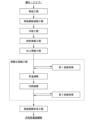
- FIG. 1 is a schematic cross-sectional view showing a grain-oriented electrical steel sheet according to an embodiment of the present invention. It is a flowchart which shows the manufacturing method of the grain-oriented electrical steel sheet concerning this embodiment.
- FIG. 1 is a schematic cross-sectional view showing a grain-oriented electrical steel sheet according to this embodiment.
- the grain-oriented electrical steel sheet 1 according to the present embodiment has a base steel plate 11 and a base steel plate 11 and an insulating coating 12 disposed in contact with the same.
- the layered structure in which the insulating coating 12 is placed in contact with the base steel plate 11 means that there is no forsterite coating, and the base steel plate 11 has a smooth surface (smooth surface equivalent to a cold-rolled steel plate). ).
- the base steel sheet 11 when viewed from the above-mentioned cut surface, is within a range of 2.0 ⁇ m in the thickness direction from the interface with the insulating coating 12. Internally oxidized SiO 2 11a is present in the interface region of the base steel plate.
- the insulating coating 12 when viewed from the above-mentioned cut surface, includes voids 12a and an oxide 12b containing iron and phosphorus. Specifically, when viewed from the cut surface, the void 12a has an area of 0.5 ⁇ m in the thickness direction from the interface with the base steel plate 11. The area ratio is 0.010 to 3.0%. Further, when viewed from the cut surface, the area ratio of the iron and phosphorus-containing oxide 12b to the area of the insulating coating 12 is 0.10 to 5.0%.
- the insulating coating is disposed in contact with the base steel plate (no forsterite coating is present), thereby ensuring the surface smoothness of the base steel plate, and the above-mentioned
- the internally oxidized SiO 2 ensures adhesion between the base steel plate and the insulating coating.
- the grain-oriented electrical steel sheet according to this embodiment has excellent iron loss characteristics.
- the internally oxidized SiO 2 described above is mainly composed of SiO 2 and is formed by oxidizing Si contained in the base steel plate during annealing.
- internal oxidation SiO 2 unique to this embodiment is created near the surface of the base material steel sheet by controlling manufacturing conditions. It is thought that when the above-mentioned internally oxidized SiO2 is formed near the surface of the base material steel plate, the Si content in the base material (matrix) around the internally oxidized SiO2 decreases, resulting in a state close to pure iron. . It is thought that the chemical interaction between this matrix in a state close to that of pure iron and P (phosphorus) contained in the insulating film increases the adhesion of the film.
- external oxidation and internal oxidation are known as oxidation forms when Si contained in the base steel plate is oxidized during annealing.
- external oxidation is an oxidation form in which an alloying element (e.g. Si) in a base steel sheet is oxidized after it has diffused to the surface of the base steel sheet, and is an oxidation that occurs in an atmosphere with low oxidizing properties. Forms an oxide film on the surface.
- internal oxidation is an oxidation form in which alloying elements (e.g. Si) in the base steel sheet are oxidized with almost no diffusion within the base steel sheet, and is an oxidation that occurs in a highly oxidizing atmosphere. Oxide forms in the form of precipitates or dendrites near the inner surface.
- internally oxidized SiO 2 is preferentially formed near the surface of the base steel sheet, so domain wall movement is not inhibited, and the area around the internally oxidized SiO 2 Since the matrix is close to that of pure iron, it is thought that the chemical interaction with the insulating film increases the adhesion of the film.
- the presence or absence of the above internally oxidized SiO 2 may be confirmed by observing a cut surface whose cutting direction is parallel to the plate thickness direction and perpendicular to the plate width direction.
- the above cut surface may be observed using a field emission transmission electron microscope (FE-TEM).
- FE-TEM field emission transmission electron microscope
- a test piece is cut out using FIB (Focused Ion Beam) processing so that the cutting direction is parallel to the plate thickness direction and perpendicular to the plate width direction, and the cross-sectional structure of this cut surface is observed in the observation field.
- FIB Fluorous Ion Beam
- FE-TEM Observe with FE-TEM at a magnification that allows each layer to be seen inside. If each layer does not fall within the observation field of view, observe the cross-sectional structure in multiple consecutive fields of view. For example, observation may be performed with a field of view of 1 ⁇ m ⁇ 1 ⁇ m or more, preferably a field of view of 2 ⁇ m ⁇ 2 ⁇ m, and a resolution of a pixel size of 1 nm/pixel or less.
- the condition may be that the acceleration voltage is 200 kV.
- the acceleration voltage is 200 kV.
- the layered region that exists at the deepest position in the sheet thickness direction, and the region where the Fe content is 80 at% or more excluding measurement noise, is the base steel sheet. , and the area excluding this base steel plate is determined to be another coating.
- the area of the above base steel plate do not take into account precipitates, inclusions, pores, etc. contained in each layer, and do not consider the area that satisfies the above quantitative analysis results as the parent phase. is determined to be the base steel plate. For example, if it is confirmed from bright-field images, dark-field images, or line analysis results that precipitates, inclusions, pores, etc. exist on the scanning line of line analysis, these areas should not be included in the matrix phase. Judgment will be made based on quantitative analysis results. Note that precipitates, inclusions, and pores can be distinguished from the parent phase by contrast, and can be distinguished from the parent phase by the abundance of constituent elements in quantitative analysis results. Note that when specifying the base steel plate, it is preferable to specify it at a position where no precipitates, inclusions, or pores are included on the scanning line of the line analysis.
- an insulating coating is arranged on the base steel plate, and the surface side of the steel plate in the region of the base steel plate determined from the quantitative analysis results of TEM-EDS is coated with the insulating coating on the base steel plate.
- the interface between the insulating coating and the base steel sheet has sufficiently few irregularities in the analysis field described below. Therefore, during analysis, the average line of the interface between the insulating coating and the base steel plate in the field of view may be treated as the interface.
- the Fe content is less than 80 atomic %
- the P content is 5 atomic % or more
- a region where the O content is 30 atomic % or more is determined to be an insulating film (phosphoric acid-based film).
- the phosphoric acid-based film may also contain aluminum, magnesium, nickel, etc. derived from phosphates. Further, silicon derived from colloidal silica may be included.
- the precipitates, inclusions, pores, etc. contained in each coating are not included in the judgment, and the matrix satisfies the above quantitative analysis results.
- the area where this occurs is determined to be a phosphoric acid coating. For example, if it is confirmed from bright-field images, dark-field images, or line analysis results that precipitates, inclusions, pores, etc. exist on the scanning line of line analysis, these areas should not be included in the matrix phase. Judgment will be made based on quantitative analysis results. Note that precipitates, inclusions, and pores can be distinguished from the parent phase by contrast, and can be distinguished from the parent phase by the abundance of constituent elements in quantitative analysis results. In addition, when specifying a phosphoric acid-based film, it is preferable to specify it at a position where no precipitates, inclusions, or pores are included on the scanning line of line analysis.
- the grain-oriented electrical steel sheet according to the present embodiment does not have an intermediate ceramic layer such as a forsterite film or an external oxide film, when the layer structure is specified by the above method, it is possible to It is confirmed that the insulating film is placed in contact with the insulating film.
- the base steel plate has a thickness of 0.17 to 0.29 mm, and the insulating coating has a thickness of 0.1 to 10 ⁇ m.
- the forsterite coating is confirmed between the base steel sheet identified by the above method and the insulating coating (phosphoric acid coating).
- this forsterite coating has an average Fe content of less than 80 atomic %, an average P content of less than 5 atomic %, an average Si content of 5 atomic % or more, and an O content on average of the entire coating. is 30 atomic % or more on average, and the Mg content is 10 atomic % or more on average.
- the quantitative analysis results of the forsterite coating are quantitative analysis results for the parent phase, which do not include the analysis results of precipitates, inclusions, pores, etc. contained in the forsterite coating.
- forsterite coatings have a thickness of 0.1 to 10 ⁇ m.
- the electrical steel sheet has an external oxide film as an intermediate ceramic layer
- the external oxide film is confirmed between the base steel sheet identified by the above method and the insulation coating (phosphoric acid coating).
- This external oxide film has, for example, an average Fe content of less than 80 atomic %, an average P content of less than 5 atomic %, an average Si content of 20 atomic % or more, and an O content, as an average of the entire oxide film.
- the Mg content satisfies an average of 30 atomic % or more, and an average Mg content of less than 10 atomic %.
- the quantitative analysis result of the external oxide film is a quantitative analysis result of the parent phase, which does not include the analysis results of precipitates, inclusions, pores, etc. contained in the external oxide film.
- the outer oxide film is between 2 and 500 nm thick.
- the base steel plate and the insulating coating disposed in contact with the base steel plate are confirmed by the above method, so that internally oxidized SiO 2 is present in the base steel plate. It is sufficient to confirm whether SiO 2 is included or not and the region in the base material steel plate where internally oxidized SiO 2 is included using the EDS installed in the FE-TEM.
- TEM-EDS a line is drawn along the thickness direction of the base steel plate identified by the above method for precipitates observed in the base steel plate in a bright field image of FE-TEM. Perform analysis and perform quantitative analysis of chemical components.
- the five elements to be quantitatively analyzed are Fe, P, Si, Al, and O. From the quantitative analysis results of TEM-EDS described above, excluding measurement noise, regions where the Fe content is less than 80 at%, the Si content is at least 30 at%, and the O content is at least 55 at% are internally oxidized into SiO2. 2 .
- the internally oxidized SiO 2 contained in the base material steel sheet is amorphous, clear diffraction spots are not observed when electron beam diffraction is performed, and broad spots are not observed. An annular electron diffraction pattern is mainly observed.
- the area ratio of the above-mentioned voids to the area of the insulating film interface region is 0.010 to 3.0%, and the insulating film If the area ratio of the oxide containing iron and phosphorus to the area of is 0.10 to 5.0%, the adhesion between the base steel plate and the insulating coating will be improved. The technical reason for this is surmised as follows.
- the atmosphere in order to form internally oxidized SiO 2 in the interface region of the base steel plate, the atmosphere is oxidized during the temperature rising process of thermal oxidation annealing performed after final annealing. Control the atmosphere.
- the temperature raising process of thermal oxidation annealing is performed in an oxidizing atmosphere, lumpy Fe oxides are likely to be formed on the surface of the base steel sheet. It is thought that the Fe oxide on the surface of the steel sheet reacts with P contained in the insulating film to form an oxide containing iron and phosphorus when the insulating film is formed, and at the same time forms voids in the insulating film.
- oxides containing iron and phosphorus and voids are likely to be formed in the insulating coating interface region where the above reaction mainly proceeds.
- voids and oxides containing iron and phosphorus are likely to be formed at the interface region of the insulating coating.
- the grain-oriented electrical steel sheet according to the present embodiment by optimally controlling the temperature raising process and soaking process of thermal oxidation annealing, voids formed in the insulation coating interface region and oxides containing iron and phosphorus are eliminated. Minimize. As a result, the adhesion between the base steel plate and the insulation coating is improved.
- the grain-oriented electrical steel sheet according to this embodiment allows voids to be included in areas other than the insulation coating interface area.
- the area ratio of the voids is preferably 2.5% or less, more preferably 2.0% or less. It is preferable that the area ratio of voids to the area of the insulating film interface region is as small as possible. However, it is industrially difficult to reduce the area ratio of voids to 0%. Therefore, the area ratio of voids may be more than 0%, and may be 0.010% or more, or 1.0% or more.
- the area ratio of the oxide containing iron and phosphorus to the area of the insulating film exceeds 5.0%, the adhesion of the film will decrease.
- the area ratio of the oxide containing iron and phosphorus is preferably 3.0% or less, more preferably 2.0% or less.
- the area ratio of the oxide containing iron and phosphorus may be more than 0%, and may be 0.10% or more, or 1.0% or more.
- the voids, iron- and phosphorus-containing oxides, and their area ratios contained in the above-mentioned insulating film may be confirmed as follows.
- the insulating coating contains voids and an oxide containing iron and phosphorus when confirmed by the method described below.
- Oxides containing iron and phosphorus may be observed with a field of view of 2 ⁇ m x 2 ⁇ m or more and a resolution of 5 nm/pixel or less. In the case of observation with only one field of view, it is difficult to obtain average information about the steel plate, so it is sufficient to observe 10 randomly selected locations separated from each other and make a judgment from a field of view of 40 ⁇ m 2 or more in total.
- electron beams are applied to precipitates observed within the insulating film in bright-field and dark-field images in order to obtain information from the target precipitates. Focusing and performing electron diffraction, the crystal structure and lattice spacing of the target precipitate are identified from the electron diffraction pattern.
- the crystal data such as the crystal structure and interplanar spacing specified above are compared with a PDF (Powder Diffraction File).
- a PDF Powder Diffraction File
- the oxide containing iron and phosphorus include FeP oxide, Fe 3 (PO 4 ) 2 oxide, Fe 2 P 2 O 7 oxide, and the like.
- JCPDS number: 03-065-2595 may be used to identify FeP oxide.
- JCPDS number: 049-1087 may be used to identify Fe 3 (PO 4 ) dioxide .
- JCPDS number: 01-076-1762 may be used to identify the Fe 2 P 2 O 7 oxide.
- the oxide containing iron and phosphorus may include an oxide containing amorphous iron and phosphorus.
- voids it is sufficient to use a field emission scanning electron microscope (FE-SEM) to observe defects and pores observed in the insulating film using SEM secondary electron images and backscattered electron images.
- FE-SEM field emission scanning electron microscope
- Those skilled in the art can confirm whether or not voids are included in the insulating coating interface region from the contrast of the secondary electron image and the reflected electron image.
- the base material steel plate and the insulating coating can be confirmed from the contrast of the backscattered electron image of SEM, etc., in the same way as with TEM.
- observation may be performed with a field of view of 10 ⁇ m ⁇ 10 ⁇ m or more and a resolution of pixel size of 10 nm/pixel or less.
- it is difficult to obtain average information about the steel plate so it is sufficient to observe 10 randomly selected locations separated from each other and make a judgment from a field of view of 40 ⁇ m 2 or more in total.
- the sample stage on which the observation sample is placed inside the SEM is tilted, a contrast corresponding to the depression on the surface of the void is obtained in the secondary electron image, and it is possible to identify the void from this contrast.
- the voids identified by the above method are observed using a backscattered electron image, the areas within the same visual field that have the same brightness as the voids are binarized, and image processing techniques are used to The area may also be derived by Note that the binarization of the image may include manual work.
- the area ratio of voids to the area of the insulating film interface region and the area ratio of the iron- and phosphorus-containing oxide to the area of the insulating film may be determined based on the above-described observation and identification. For example, find the area of the insulation coating interface region within a range of 0.5 ⁇ m in the thickness direction from the interface with the base steel plate within the insulation coating, and the total area of voids included in the insulation coating interface region. , just calculate its area ratio. Similarly, the area ratio of the area ratio can be calculated by determining the area of the insulating film and the total area of the oxide containing iron and phosphorus contained in the insulating film. The above area and area ratio may be determined by image analysis. In addition, image binarization for image analysis is based on the above identification results of voids and oxides containing iron and phosphorus. The image may be binarized by coloring the oxide.
- the grain-oriented electrical steel sheet In the grain-oriented electrical steel sheet according to the present embodiment, internally oxidized SiO 2 is contained in the base steel plate interface region, and the area ratio of voids in the insulation coating interface region is 0.010 to 3.0% or less. In addition, if the area ratio of the oxide containing iron and phosphorus in the insulating coating is 0.10 to 5.0% or less, the adhesion between the base steel plate and the insulating coating is improved.
- the grain-oriented electrical steel sheet according to the present embodiment when viewed from a cut surface whose cutting direction is parallel to the sheet thickness direction and perpendicular to the sheet width direction, internally oxidized SiO 2 It is preferable that the area ratio of is 2.0% or more. When internally oxidized SiO 2 satisfies the above conditions, internally oxidized SiO 2 preferentially exists near the surface of the base steel sheet, and as a result, film adhesion is preferably improved.
- the above area ratio is preferably 5% or more, more preferably 10% or more.
- the upper limit of the above-mentioned area ratio is not particularly limited, and may be 100% because it is more preferable. However, it is not easy to make the above area ratio 100% industrially, so the above area ratio is preferably 80% or less, preferably 50% or less, and 20% or less. It is preferably 15% or less, and more preferably 15% or less.
- the above-mentioned area ratio may be determined based on the above-mentioned observation and identification using FE-TEM. For example, the total area of the base steel plate interface region within 2.0 ⁇ m in the thickness direction from the interface with the insulating coating within the base steel plate and the internally oxidized SiO 2 contained in the base steel plate interface area. All you have to do is find the area and calculate the area ratio.
- the above area and area ratio may be determined by image analysis.
- the binarization of the image for image analysis was performed by manually coloring the internal oxidation SiO 2 on the tissue photograph and binarizing the image based on the identification results of internal oxidation SiO 2 described above. Good too.
- the internally oxidized SiO 2 specified above has a dendrite shape when viewed from a cut surface whose cutting direction is parallel to the sheet thickness direction and perpendicular to the sheet width direction. is preferred. Specifically, it is preferable that the isoperimetric constant derived from the area and circumferential length of the internally oxidized SiO 2 is less than 0.350 when viewed in the cut plane. When internally oxidized SiO 2 satisfies the above conditions, film adhesion is preferably improved.
- the dendrite shape (isoperiodic constant) of internally oxidized SiO 2 may be confirmed by the following method.
- the above-mentioned isoperimetric constant is derived according to 4 ⁇ (area) ⁇ (periphery) 2 , and represents the degree of unevenness such as dendrite shape. It represents 1 when it is an ideal circle, and the upper limit is 1, and the smaller the value from 1, the more complex the uneven shape of the surface is.
- the area may be calculated by image analysis from the FE-TEM microstructure photograph or manually, similarly to when calculating the area ratio of internally oxidized SiO 2 described above.
- the circumference may be determined by image analysis from the tissue photograph using image analysis software such as imageJ.
- the above isoperimetric constant is preferably less than 0.20, more preferably less than 0.10.
- the lower limit of the above-mentioned isoperimetric constant is not particularly limited and is preferably as small as possible; however, since it is not industrially easy to set the isoperimetric constant to 0, the above-mentioned isoperimetric constant may be set to 0.020 or more. .
- the above-mentioned cut surface was observed at 10 observation points spaced apart from each other on the sheet surface
- the above-mentioned internally oxidized SiO 2 was found at 5 or more points. It is preferably included in the observation location.
- the internally oxidized SiO 2 satisfies the above conditions, the internally oxidized SiO 2 is distributed over a wide area on the surface of the grain-oriented electrical steel sheet, and as a result, the film adhesion is preferably improved.
- the number of observation points containing the above-mentioned internally oxidized SiO 2 is eight or more.
- the upper limit of the observation points containing the internally oxidized SiO 2 described above is not particularly limited, and the larger the observation point, the better, so it may be 10 points.
- the number of observation points containing the internally oxidized SiO 2 described above may be nine or less.
- the voids were smaller than the area of the insulation coating interface region. Observation locations where the area ratio is 0.010% or more and 3.0% or less, and where the area ratio of the oxide containing iron and phosphorus is 0.10% or more and 5.0% or less with respect to the area of the insulating coating. However, it is preferable that the number of locations is five or more. Note that the voids described above may be observed with a field of view of 10 ⁇ m ⁇ 10 ⁇ m, and the oxide containing iron and phosphorus may be observed with a field of view of 2 ⁇ m ⁇ 2 ⁇ m.
- the voids and the oxide containing iron and phosphorus satisfy the above conditions, the voids and the oxide containing iron and phosphorus are controlled over a wide range on the surface of the grain-oriented electrical steel sheet. As a result, film adhesion is preferably improved.
- the number of observation points where voids and oxides containing iron and phosphorus satisfy the above conditions is preferably 7 or more, more preferably 8 or more.
- the upper limit of the observation points where the void and the oxide containing iron and phosphorus satisfy the above conditions is not particularly limited, and the larger the observation point, the better, so it may be 10 points. However, it is not easy to industrially identify 10 observation points where voids and oxides containing iron and phosphorus satisfy the above conditions.
- the number of observation points that satisfy the following conditions may be nine or less.
- the remaining coating area ratio is preferably 90% or more, and preferably 95% or more. It is more preferable that The upper limit of the coating remaining area ratio is not particularly limited, but may be, for example, 100%.
- the above coating remaining area ratio may be evaluated by the coating remaining ratio when a test piece is wound around a cylinder with a diameter of 20 mm and bent by 180°.
- the area ratio of the remaining surface of the coating to the area of the steel plate in contact with the cylinder may be calculated, and the area of the steel plate in contact with the roll may be determined by calculation.
- the area of the remaining surface may be determined by taking a photograph of the steel plate after the test and performing image analysis on the photographic image.
- the base steel sheet has a chemical composition that includes basic elements, optionally includes selected elements, and the remainder consists of Fe and impurities.
- the base material steel plate has a chemical composition in mass%, Si: 3.0 to 4.0%, Mn: 0.010 to 0.50%, C: 0 to 0.010%, N: 0 to 0.010%, Acid-soluble Al: 0 to 0.020%, P: 0-0.040%, Total of S and Se: 0 to 0.010%, Sn: 0 to 0.50%, Cu: 0 to 0.50%, Cr: 0 to 0.50%, Sb: 0 to 0.50%, Mo: 0 to 0.10%, Bi: 0-0.10%, , and the remainder is Fe and impurities.
- the base material steel plate has a chemical composition in mass%, Sn: 0.0050 to 0.50%, Cu: 0.010 to 0.50%, Cr: 0.010-0.50%, Sb: 0.010 to 0.50%, Mo: 0.0050 to 0.10%, Bi: 0.00050 to 0.10%, It may contain at least one selected from the group consisting of:
- Si 3.0 to 4.0% by mass Si (silicon) is a basic element for the base steel plate. If the Si content is less than 3.0%, eddy current loss cannot be sufficiently reduced, and good magnetic properties cannot be obtained. Therefore, the Si content is set to 3.0% or more.
- the Si content is preferably 3.10% or more, more preferably 3.20% or more.
- the Si content exceeds 4.0%, the steel sheet will become brittle and the threadability will be significantly deteriorated during manufacturing, so the Si content should be 4.0% or less.
- the Si content is preferably 3.70% or less, more preferably 3.60% or less, and even more preferably 3.50% or less.
- Mn 0.010 to 0.50% by mass Mn (manganese) is a basic element for base steel sheets. If the Mn content is less than 0.010%, MnS and MnSe, which function as inhibitors, are difficult to form, secondary recrystallization does not proceed sufficiently, and good magnetic properties cannot be obtained. Therefore, the Mn content is set to 0.010% or more.
- the Mn content is preferably 0.030% or more, more preferably 0.050% or more.
- the Mn content exceeds 0.50%, the steel undergoes phase transformation during secondary recrystallization annealing, secondary recrystallization does not proceed sufficiently, and good magnetic properties cannot be obtained.
- the amount shall be 0.50% or less.
- the Mn content is preferably 0.20% or less, more preferably 0.15% or less, and even more preferably 0.10% or less.
- C 0 to 0.010% by mass C (carbon) is an element of choice for the base steel plate.
- C is contained in steel slabs, but if excessive C remains in the base steel plate after final annealing, good iron loss characteristics may not be obtained. Therefore, the C content of the base steel plate may be 0.010% or less.
- the C content is preferably 0.0050% or less, more preferably 0.0030% or less.
- the lower limit of the C content of the base steel plate is not particularly limited, and may be 0%. However, since it is not industrially easy to reduce the C content to 0%, the C content may be greater than 0% or may be greater than 0.00010%.
- N 0 to 0.010% by mass N (nitrogen) is an element of choice for the base steel sheet. N is contained in steel slabs, but if excessive N remains in the base steel plate after final annealing, it may have a negative effect on magnetic properties. Therefore, the N content of the base steel plate may be 0.010% or less. The N content is preferably 0.0090% or less, more preferably 0.0080% or less. On the other hand, the lower limit of the N content of the base material steel plate is not particularly limited, and may be 0%. However, since N has the effect of forming AlN and acting as an inhibitor during secondary recrystallization, the N content may be greater than 0% or may be greater than or equal to 0.00010%.
- Acid-soluble Al 0 to 0.020% by mass Acid-soluble Al (sol.Al) is an element of choice for base steel sheets. Acid-soluble Al is contained in steel slabs, but if excessive acid-soluble Al remains in the base steel plate after final annealing, it may have a negative effect on magnetic properties. Therefore, the acid-soluble Al content of the base steel plate may be 0.020% or less. The acid-soluble Al content is preferably 0.0150% or less, more preferably 0.010% or less. On the other hand, the lower limit of the acid-soluble Al content of the base steel sheet is not particularly limited, and may be 0%. However, since acid-soluble Al forms AlN and has an effect as an inhibitor during secondary recrystallization, the acid-soluble Al content may be greater than 0% or may be 0.00010% or more.
- P 0 to 0.040% by mass
- P phosphorus
- the P content is preferably 0.030% or less, more preferably 0.020% or less.
- the lower limit of the P content is not particularly limited and may be 0%. However, since P has the effect of improving the texture and improving the magnetic properties of the steel sheet, the P content may be greater than 0%, or may be greater than 0.0020%.
- Total of S and Se 0 to 0.010% by mass
- S (sulfur) and Se (selenium) are selective elements for the base steel plate.
- S and Se are contained in steel slabs, but if excessive S and Se remain in the base steel plate after finish annealing, it may have an adverse effect on magnetic properties. Therefore, the total content of S and Se in the base steel plate may be 0.010% or less.
- the lower limit of the total content of S and Se in the base steel plate is not particularly limited, and may be 0%. However, since S and Se form MnS and MnSe and have an effect as an inhibitor during secondary recrystallization, the total content of S and Se may be more than 0%, and may be 0.0050% or more. Good too.
- Sn 0 to 0.50% by mass Sn (tin) is a selective element for the base steel plate. If the Sn content exceeds 0.50%, secondary recrystallization becomes unstable, which may adversely affect magnetic properties. Therefore, the Sn content may be 0.50% or less.
- the Sn content is preferably 0.30% or less, more preferably 0.150% or less.
- the lower limit of the Sn content is not particularly limited and may be 0%. However, since Sn has the effect of increasing the degree of integration of the Goss orientation and improving the magnetic properties, the Sn content may be greater than 0%, or may be greater than 0.0050%.
- Cu 0 to 0.50% by mass Cu (copper) is an element of choice for the base steel sheet. If the Cu content exceeds 0.50%, the steel sheet may become brittle during hot rolling. Therefore, the Cu content may be 0.50% or less.
- the Cu content is preferably 0.30% or less, more preferably 0.10% or less.
- the lower limit of the Cu content is not particularly limited and may be 0%. However, since Cu has the effect of increasing the degree of integration of Goss orientation and improving magnetic properties, the Cu content may be greater than 0%, or may be greater than 0.010%.
- Cr 0 to 0.50% by mass Cr (chromium) is an element of choice for base steel sheets. If the Cr content exceeds 0.50%, Cr oxides may be formed, which may adversely affect magnetic properties. Therefore, the Cr content may be 0.50% or less.
- the Cr content is preferably 0.30% or less, more preferably 0.10% or less.
- the lower limit of the Cr content is not particularly limited and may be 0%. However, since Cr has the effect of increasing the degree of integration of Goss orientation and improving magnetic properties, the Cr content may be greater than 0%, or may be greater than 0.010%.
- Sb 0 to 0.50% by mass Sb (antimony) is a selective element for the base steel plate.
- Sb content exceeds 0.50%, magnetic properties may be adversely affected. Therefore, the Sb content may be 0.50% or less.
- the Sb content is preferably 0.30% or less, more preferably 0.10% or less.
- the lower limit of the Sb content is not particularly limited and may be 0%. However, since Sb functions as an inhibitor and has the effect of stabilizing secondary recrystallization, the Sb content may be more than 0% or more than 0.010%.
- Mo 0 to 0.10% by mass Mo (molybdenum) is an element of choice for the base steel plate. If the Mo content exceeds 0.10%, problems may arise in the rollability of the steel sheet. Therefore, the Mo content should just be 0.10% or less. Mo content is preferably 0.08% or less, more preferably 0.05% or less. On the other hand, the lower limit of the Mo content is not particularly limited and may be 0%. However, since Mo has the effect of increasing the degree of integration of the Goss orientation and improving the magnetic properties, the Mo content may be greater than 0% or may be greater than or equal to 0.0050%.
- Bi 0 to 0.10% by mass Bi (bismuth) is an element of choice for the base steel plate. If the Bi content exceeds 0.10%, the sheet threadability during cold rolling may deteriorate. Furthermore, if excessive Bi remains due to insufficient purification during final annealing, the magnetic properties may be adversely affected. Therefore, the Bi content may be 0.10% or less.
- the Bi content is preferably 0.050% or less, more preferably 0.020% or less, and even more preferably 0.0010% or less.
- the lower limit of the Bi content is not particularly limited and may be 0%. However, since Bi has the effect of improving magnetic properties, the Bi content may be greater than 0%, or may be greater than 0.00050%.
- the base steel sheet of the grain-oriented electrical steel sheet according to this embodiment may contain impurities.
- impurities refer to things that are mixed in from ores and scraps used as raw materials or from the manufacturing environment when steel is manufactured industrially.
- the chemical composition of the base steel sheet described above may be measured by a general analytical method. For example, it may be measured using ICP-AES (Inductively Coupled Plasma-Atomic Emission Spectrometry). Note that acid-soluble Al may be measured by ICP-AES using a filtrate obtained by thermally decomposing a sample with an acid. Further, C and S may be measured using a combustion-infrared absorption method, N using an inert gas melting-thermal conductivity method, and O using an inert gas melting-non-dispersive infrared absorption method.
- ICP-AES Inductively Coupled Plasma-Atomic Emission Spectrometry
- acid-soluble Al may be measured by ICP-AES using a filtrate obtained by thermally decomposing a sample with an acid.
- C and S may be measured using a combustion-infrared absorption method, N using an inert gas melting-thermal conductivity method, and O using an inert gas melting-non-dispersive
- the above chemical composition is the component of the base steel plate. If the grain-oriented electrical steel sheet serving as the measurement sample has an insulating coating or the like on its surface, the coating or the like is removed by the method below before measuring the chemical composition.
- a grain-oriented electrical steel sheet having a coating may be immersed in a high-temperature alkaline solution. Specifically, by immersing it in a sodium hydroxide aqueous solution containing 30 to 50% by mass of NaOH and 50 to 70% by mass of H 2 O at 80 to 90°C for 5 to 10 minutes, washing with water and drying, The insulation coating can be removed from grain-oriented electrical steel sheets. Note that the immersion time in the above sodium hydroxide aqueous solution may be changed depending on the thickness of the insulating film.
- the grain-oriented electrical steel sheet according to the present embodiment does not have a forsterite coating
- the electrical steel sheet from which the insulation coating has been removed by the above method may be immersed in high-temperature hydrochloric acid.
- the preferred concentration of hydrochloric acid for removing the forsterite film to be dissolved was determined in advance, and the sample was immersed in hydrochloric acid of this concentration (for example, 30 to 40% by mass hydrochloric acid) at 80 to 90°C for 1 to 5 minutes.
- the forsterite coating can be removed by washing with water and drying.
- each coating is removed by using different processing solutions, such as using an alkaline solution to remove an insulating coating and using hydrochloric acid to remove a forsterite coating.
- the method for manufacturing the grain-oriented electrical steel sheet according to this embodiment is not limited to the following method.
- the following manufacturing method is one example for manufacturing the grain-oriented electrical steel sheet according to this embodiment.
- FIG. 2 is a flowchart illustrating the method for manufacturing a grain-oriented electrical steel sheet according to the present embodiment.
- the method for producing a grain-oriented electrical steel sheet according to the present embodiment includes a hot rolling step of hot rolling a slab (steel billet) having a predetermined chemical composition to obtain a hot rolled steel sheet, and annealing the hot rolled steel sheet to obtain a hot rolled steel sheet.
- a hot rolled steel plate annealing process to obtain an annealed plate
- a cold rolling process to obtain a cold rolled steel plate by subjecting the hot rolled annealed plate to one cold rolling or multiple cold rollings via annealing
- a cold rolling process to obtain a cold rolled steel plate.
- a decarburization annealing process in which a decarburized annealed plate is obtained by performing charcoal annealing, a finish annealing process in which a finish annealing is performed after applying an annealing separator to the decarburized annealed plate, and a thermal oxidation process is performed on the finish annealed plate.
- Mainly includes and.
- the method for manufacturing a grain-oriented electrical steel sheet includes: Including a hot rolling process, a hot rolled steel plate annealing process, a cold rolling process, a decarburization annealing process, a final annealing process, a thermal oxidation annealing process, and an insulating film forming process,
- a hot rolling process a hot rolled steel plate annealing process, a cold rolling process, a decarburization annealing process, a final annealing process, a thermal oxidation annealing process, and an insulating film forming process.
- the steel plate is annealed and separated in which, in terms of solid content, alumina is 20 to 99.5 mass%, bismuth chloride is 0.5 to 20 mass%, and the balance is magnesia and impurities.
- finish annealing is carried out.
- the steel plate after the final annealing process is heated from room temperature to 800 to 1100 in an atmosphere where the oxygen concentration is less than 1.0 volume % and the oxygen potential PH 2 O / PH 2 is 0.50 to 100.
- Heat to a temperature range of °C As a soaking process, the steel plate after the temperature raising process is heated to 800 to 800 ml in an atmosphere where the oxygen concentration is less than 1.0 volume % and the oxygen potential PH 2 O/PH 2 is from 0.010 to less than 0.50. Soak at a temperature range of 1100°C for 5 to 200 seconds.
- a steel billet for example, a steel ingot such as a slab
- a predetermined chemical composition is hot rolled.
- the chemical composition of a slab (steel billet) to be subjected to a hot rolling process is as follows: Si: 3.0 to 4.0%, Mn: 0.010 to 0.50%, C: 0.020-0.20%, N: 0.0020-0.020%, Acid-soluble Al: 0.010 to 0.050%, P: 0-0.040%, Total of S and Se: 0.0010 to 0.040%, Sn: 0 to 0.50%, Cu: 0 to 0.50%, Cr: 0 to 0.50%, Sb: 0 to 0.50%, Mo: 0 to 0.10%, Bi: 0-0.10%, , and the remainder is Fe and impurities.
- the above-mentioned slab (steel billet) has a chemical composition in mass%, Sn: 0.0050 to 0.50%, Cu: 0.010 to 0.50%, Cr: 0.010-0.50%, Sb: 0.010 to 0.50%, Mo: 0.0050 to 0.10%, Bi: 0.00050 to 0.10%, It may contain at least one selected from the group consisting of:
- Si 3.0 to 4.0% by mass Si (silicon) is a basic element for steel slabs. If the Si content is less than 3.0%, eddy current loss cannot be sufficiently reduced, and good magnetic properties cannot be obtained. Therefore, the Si content is set to 3.0% or more.
- the Si content is preferably 3.10% or more, more preferably 3.20% or more.
- the Si content exceeds 4.0%, the steel sheet will become brittle and the threadability will be significantly deteriorated during manufacturing, so the Si content should be 4.0% or less.
- the Si content is preferably 3.70% or less, more preferably 3.60% or less, and even more preferably 3.50% or less.
- Mn 0.010 to 0.50% by mass Mn (manganese) is a basic element for steel slabs. If the Mn content is less than 0.010%, MnS and MnSe, which function as inhibitors, are difficult to form, secondary recrystallization does not proceed sufficiently, and good magnetic properties cannot be obtained. Therefore, the Mn content is set to 0.010% or more. The Mn content is preferably 0.030% or more, more preferably 0.050% or more. On the other hand, if the Mn content exceeds 0.50%, the steel undergoes phase transformation during secondary recrystallization annealing, secondary recrystallization does not proceed sufficiently, and good magnetic properties cannot be obtained. The amount shall be 0.50% or less. The Mn content is preferably 0.20% or less, more preferably 0.15% or less, and even more preferably 0.10% or less.
- C 0.020-0.20% mass%
- C is a basic element for steel slabs.
- C is included for the purpose of increasing the degree of Goss orientation in secondary recrystallization.
- the C content required for improving magnetic properties is 0.020% or more, preferably 0.040% or more in the slab.
- the C content, as a slab is 0.20% or less, preferably 0.15% or less, more preferably 0.10% or less.
- N is a basic element for steel slabs.
- N is an element necessary to form AlN, which is an inhibitor, and to increase the degree of accumulation of Goss orientation during secondary recrystallization.
- the N content required for forming the inhibitor is 0.0020% or more, preferably 0.0040% or more, and more preferably 0.0060% or more as a slab.
- the N content, as a slab is 0.020% or less, preferably 0.015% or less, more preferably 0.010% or less.
- N needs to be purified during final annealing.
- Acid-soluble Al 0.010 to 0.050% by mass
- Acid-soluble Al (aluminum) (sol.Al) is a basic element for steel slabs.
- Acid-soluble Al is an element necessary to form AlN, which is an inhibitor, and to enhance magnetic properties.
- the content of acid-soluble Al in the slab is 0.010% or more, preferably 0.015% or more, and more preferably 0.020% or more.
- the content of acid-soluble Al in the slab is 0.050% or less, preferably 0.040% or less, and more preferably 0.030% or less.
- acid-soluble Al needs to be purified from the base steel sheet during final annealing.
- P 0 to 0.040% by mass
- P phosphorus
- the P content is preferably 0.030% or less, more preferably 0.020% or less.
- the lower limit of the P content is not particularly limited and may be 0%. However, since P has the effect of improving the texture and improving the magnetic properties of the steel sheet, the P content may be greater than 0%, or may be greater than 0.0020%.
- Total of S and Se 0.0010 to 0.040% by mass
- S (sulfur) and Se (selenium) are basic elements for steel slabs.
- S and Se are elements that form the inhibitor MnS.
- the total content of S and Se is 0.0010% or more, preferably 0.010% or more, and more preferably 0.020% or more as a slab.
- the total content of S and Se is 0.040% or less, preferably 0.0350% or less, more preferably 0.030% or less as a slab. If excessive S and Se remain in the final product, they may cause magnetic deterioration. Therefore, S and Se also need to be purified from the base steel sheet during final annealing.
- Sn 0 to 0.50% by mass Sn (tin) is an element of choice for steel slabs. If the Sn content exceeds 0.50%, secondary recrystallization becomes unstable, which may adversely affect magnetic properties. Therefore, the Sn content may be 0.50% or less.
- the Sn content is preferably 0.30% or less, more preferably 0.150% or less.
- the lower limit of the Sn content is not particularly limited and may be 0%. However, since Sn has the effect of increasing the degree of integration of the Goss orientation and improving the magnetic properties, the Sn content may be greater than 0%, or may be greater than 0.0050%.
- Cu 0 to 0.50% by mass Cu (copper) is an element of choice for steel slabs. If the Cu content exceeds 0.50%, the steel sheet may become brittle during hot rolling. Therefore, the Cu content may be 0.50% or less.
- the Cu content is preferably 0.30% or less, more preferably 0.10% or less.
- the lower limit of the Cu content is not particularly limited and may be 0%. However, since Cu has the effect of increasing the degree of integration of Goss orientation and improving magnetic properties, the Cu content may be greater than 0%, or may be greater than 0.010%.
- Cr 0 to 0.50% by mass Cr (chromium) is an element of choice for steel slabs. If the Cr content exceeds 0.50%, Cr oxides may be formed, which may adversely affect magnetic properties. Therefore, the Cr content may be 0.50% or less.
- the Cr content is preferably 0.30% or less, more preferably 0.10% or less.
- the lower limit of the Cr content is not particularly limited and may be 0%. However, since Cr has the effect of increasing the degree of integration of Goss orientation and improving magnetic properties, the Cr content may be greater than 0%, or may be greater than 0.010%.
- Sb 0 to 0.50% by mass Sb (antimony) is an element of choice for steel slabs.
- Sb content exceeds 0.50%, magnetic properties may be adversely affected. Therefore, the Sb content may be 0.50% or less.
- the Sb content is preferably 0.30% or less, more preferably 0.10% or less.
- the lower limit of the Sb content is not particularly limited and may be 0%. However, since Sb functions as an inhibitor and has the effect of stabilizing secondary recrystallization, the Sb content may be more than 0% or more than 0.010%.
- Mo 0 to 0.10% by mass Mo (molybdenum) is an element of choice for steel slabs. If the Mo content exceeds 0.10%, problems may arise in the rollability of the steel plate. Therefore, the Mo content should just be 0.10% or less. Mo content is preferably 0.08% or less, more preferably 0.05% or less. On the other hand, the lower limit of the Mo content is not particularly limited and may be 0%. However, since Mo has the effect of increasing the degree of integration of the Goss orientation and improving the magnetic properties, the Mo content may be greater than 0% or may be greater than or equal to 0.0050%.
- Bi 0 to 0.10% by mass Bi (bismuth) is an element of choice for steel slabs. If the Bi content exceeds 0.10%, the sheet threadability during cold rolling may deteriorate. Furthermore, if excessive Bi remains due to insufficient purification during final annealing, the magnetic properties may be adversely affected. Therefore, the Bi content may be 0.10% or less.
- the Bi content is preferably 0.050% or less, more preferably 0.020% or less, and even more preferably 0.0010% or less.
- the lower limit of the Bi content is not particularly limited and may be 0%. However, since Bi has the effect of improving magnetic properties, the Bi content may be greater than 0%, or may be greater than 0.00050%.
- the steel slab (slab) subjected to the hot rolling process may contain impurities.
- impurities refer to things that are mixed in from ores and scraps used as raw materials or from the manufacturing environment when steel is manufactured industrially.
- the chemical composition of the steel slab (slab) to be subjected to the hot rolling process may be measured in the same manner as the chemical composition of the base steel plate described above.
- the steel billet is heat treated.
- the heating temperature may be, for example, 1200°C or more and 1600°C or less.
- the lower limit of the heating temperature is preferably 1280°C, and the upper limit of the heating temperature is preferably 1500°C.
- the heated steel billet is then hot rolled.
- the thickness of the hot rolled steel plate after hot rolling is preferably in the range of, for example, 2.0 mm or more and 3.0 mm or less.
- Hot-rolled steel plate annealing process In the hot-rolled steel plate annealing process, the hot-rolled steel plate obtained in the hot-rolling process is annealed. This hot-rolled steel plate annealing causes recrystallization in the steel plate, and finally it becomes possible to realize good magnetic properties.
- the conditions for annealing the hot rolled steel sheet are not particularly limited, but for example, the hot rolled steel sheet may be annealed in a temperature range of 900 to 1200° C. for 10 seconds to 5 minutes. Further, after annealing the hot rolled steel sheet and before cold rolling, the surface of the hot rolled annealed sheet may be pickled.
- the hot rolled annealed sheet after the hot rolled steel sheet annealing process is subjected to one cold rolling or multiple cold rolling with intermediate annealing in between.
- the hot-rolled annealed plate has a good steel plate shape due to hot-rolled steel plate annealing, the possibility that the steel plate will break during the first cold rolling can be reduced.
- the heating method for intermediate annealing is not particularly limited. Further, the cold rolling may be performed in three or more times with intermediate annealing in between, but since the manufacturing cost increases, it is preferable to perform the cold rolling once or twice.
- the final cold rolling reduction ratio in cold rolling is, for example, in the range of 80% or more and 95% or less. do it.
- the thickness of the cold-rolled steel sheet subjected to cold rolling is usually the thickness (final sheet thickness) of the base steel sheet of the grain-oriented electrical steel sheet finally manufactured.
- the thickness of the cold rolled steel sheet after cold rolling is preferably in the range of, for example, 0.17 mm or more and 0.29 mm or less.
- Decarburization annealing process In the decarburization annealing process, the cold rolled steel sheet obtained in the cold rolling process is decarburized and annealed. This decarburization annealing removes C contained in the cold rolled steel sheet, causing primary recrystallization. Decarburization annealing is preferably performed in a humid atmosphere in order to remove C contained in the cold rolled steel sheet. For example, decarburization annealing is performed in a humid atmosphere at a temperature range of 700 to 1000°C for 10 seconds to 10 minutes. That's fine.
- nitriding treatment may be performed after decarburization annealing and before applying the annealing separator.
- a nitriding treatment is performed on a decarburized annealed steel sheet after decarburization annealing to produce a nitrided steel sheet.
- annealing may be performed at a temperature range of 700 to 850° C. for 10 to 60 seconds in an atmosphere containing hydrogen, nitrogen, and a gas having nitriding ability such as ammonia.
- an annealing separator is applied to the decarburized annealed plate obtained in the decarburization annealing process, and final annealing is performed. Finish annealing may be performed by annealing the steel plate for a long time in a coiled state. In order to prevent the coiled steel sheet from seizing during final annealing, an annealing separator is applied to the decarburized annealed sheet and dried before final annealing.
- the annealing separator contains magnesia (MgO), alumina (Al 2 O 3 ), and bismuth chloride.
- MgO magnesia
- Al 2 O 3 alumina
- bismuth chloride in terms of solid content, alumina is 20 to 99.5% by mass, bismuth chloride is 0.5 to 20% by mass, and the remainder is magnesia and impurities.
- the above bismuth chloride may be bismuth oxychloride (BiOCl), bismuth trichloride (BiCl 3 ), or the like.
- the annealing conditions for finish annealing are not particularly limited, and known conditions may be adopted as appropriate.
- a decarburized annealed plate coated with an annealing separator and dried may be held at a temperature range of 1000° C. or higher and 1300° C. or lower for 10 hours or more and 60 hours or less.
- the atmosphere during final annealing may be, for example, a nitrogen atmosphere or a mixed atmosphere of nitrogen and hydrogen.
- the surface of the finish annealing plate may be washed with water to remove powder.
- the atmosphere during final annealing may be changed to a hydrogen atmosphere and the purification treatment may be performed.
- the purification treatment Through this purification treatment, elements such as Al, N, S, and Se contained in the steel composition of the steel plate are discharged to the outside of the system, and the steel plate is purified.
- Thermal oxidation annealing process In the thermal oxidation annealing process, thermal oxidation annealing (heat treatment) is performed on the finish annealed plate obtained in the finish annealing process. Furthermore, a first surface treatment may be performed before the heat treatment, and a second surface treatment may be performed after the heat treatment.
- the finish annealed plate obtained in the finish annealing step may be subjected to a first surface treatment if necessary.
- pickling conditions are not particularly specified, but, for example, the finish annealed plate may be immersed in an acid (first treatment liquid) of a specific concentration.
- the first treatment liquid may contain at least one of hydrochloric acid, sulfuric acid, nitric acid, and phosphoric acid, have a total acid concentration of 1 to 20% by mass, and have a liquid temperature of 50 to 90°C.
- the finish annealed plate may be surface treated for 3 to 60 seconds.
- the surface of the finish annealed plate is brought into an active surface state, but on the other hand, it is preferable to perform the surface treatment under conditions that do not create etch pits on the surface of the finish annealed plate.
- each of the above conditions may be controlled in a composite manner and inseparably. For example, if you want to increase the pickling strength under some of the above conditions, change the pickling strength under other conditions to reduce the active state of the surface and the smooth state of the surface. All you have to do is make it compatible.
- Those skilled in the art can control the surface including the pickling behavior, so if the effects of each of the above conditions on the pickling strength are considered, it is possible to control the surface state by combining the above conditions. be.
- the total acid concentration of the first treatment liquid is less than 1% by mass, it is difficult to bring the surface of the finish annealed plate into an active surface state, and internal oxidation SiO 2 is difficult to be formed in the next heat treatment.
- the total acid concentration of the first treatment liquid exceeds 20% by mass, etch pits are likely to be formed on the surface of the finish annealed plate.
- the temperature of the first treatment liquid is less than 50°C, an active surface state cannot be obtained, and if the temperature of the first treatment liquid is over 90°C, etch pits are likely to be formed.
- the treatment time of the first surface treatment is less than 3 seconds, an active surface state cannot be obtained, and if the treatment time of the first surface treatment is more than 60 seconds, etch pits are likely to be formed.
- thermal oxidation annealing is performed on the finish annealed plate after the finish annealing step or the finish annealed plate after the first surface treatment.
- the temperature of the finish annealed plate is raised from room temperature and heat treatment is carried out within a temperature range of 800 to 1100°C. , and the soaking process at a soaking temperature within the temperature range of 800 to 1100° C. are individually controlled.
- the steel plate is heated to a temperature range of 800 to 1100°C from room temperature in an atmosphere in which the oxygen concentration is less than 1.0 volume % and the oxygen potential PH 2 O / PH 2 is 0.50 to 100. do.
- the oxygen potential PH 2 O/PH 2 can be defined by the ratio of the water vapor partial pressure PH 2 O and the hydrogen partial pressure PH 2 in the atmosphere.
- internally oxidized SiO 2 is preferably formed near the surface of the finish annealed plate by including Bi chloride in the annealing separator and setting the atmosphere during the heating process to the above atmosphere. be done.
- each of the above conditions is controlled in a composite manner and inseparably. For example, if each condition is controlled within the range of the above conditions to increase the oxidizing property, internal oxidation is likely to occur, and if each condition is controlled within the above range to weaken the oxidizing property, external oxidation is likely to occur. .
- Those skilled in the art can control the oxidation reaction by combining the above conditions to form the desired oxide.
- the oxygen concentration is set to less than 1.0% by volume.
- the oxygen concentration is preferably 0.50% by volume or less, more preferably 0.10% by volume or less.
- the lower limit of the oxygen concentration is not particularly limited, and is preferably as small as possible.
- the oxygen concentration may be set to 1.0 ⁇ 10 ⁇ 20 % by volume or more.
- the oxygen concentration is preferably 1.0 ⁇ 10 ⁇ 19 volume % or more, more preferably 1.0 ⁇ 10 ⁇ 18 volume % or more.
- the oxygen potential PH 2 O/PH 2 is set to 0.50 or more.
- the oxygen potential PH 2 O/PH 2 is preferably 0.60 or more, more preferably 0.70 or more.
- the oxygen potential PH 2 O/PH 2 is set to 100 or less.
- the oxygen potential PH 2 O/PH 2 is preferably 90 or less, more preferably 80 or less.
- the oxygen potential PH 2 O/PH 2 can be derived from the hydrogen concentration and dew point in the annealing atmosphere.
- the temperature to be reached is 800°C or higher.
- the temperature reached is preferably 830°C or higher, more preferably 860°C or higher.
- the temperature to be reached is 1100°C or less.
- the temperature reached is preferably 1050°C or lower, more preferably 1000°C or lower.
- the temperature increase rate in the temperature increase process is not particularly limited, it is preferable that the temperature increase rate is 10°C/second or more, and it is preferable that the temperature increase rate is 100°C/second or less.
- the steel plate In the soaking process, the steel plate is heated in a temperature range of 800 to 1100°C in an atmosphere where the oxygen concentration is less than 1.0% by volume and the oxygen potential PH 2 O / PH 2 is less than 0.010 to 0.50. Soak for 5-200 seconds.
- the lumpy oxides such as Fe 2 SiO 4 and FeO formed during the temperature rise can be reduced and preferably rendered harmless.
- oxides such as Fe 2 SiO 4 and FeO are reduced, but internally oxidized SiO 2 is preferably not reduced.
- each of the above conditions is controlled in a composite manner and inseparably.
- oxides such as Fe 2 SiO 4 and FeO it is easy to reduce oxides such as Fe 2 SiO 4 and FeO, but if the reducibility is increased too much, even internally oxidized SiO 2 may be reduced. .
- Those skilled in the art can control the reduction reaction by combining the above conditions to preferentially reduce only oxides such as Fe 2 SiO 4 and FeO.
- the oxygen concentration is set to less than 1.0% by volume.
- the oxygen concentration is preferably 0.50% by volume or less, more preferably 0.10% by volume or less.
- the lower limit of the oxygen concentration is not particularly limited, and is preferably as small as possible.
- the oxygen concentration may be set to 1.0 ⁇ 10 ⁇ 20 % by volume or more.
- the oxygen concentration is preferably 1.0 ⁇ 10 ⁇ 19 volume % or more, more preferably 1.0 ⁇ 10 ⁇ 18 volume % or more.
- the oxygen potential PH 2 O/PH 2 is set to less than 0.50.
- the oxygen potential PH 2 O/PH 2 is preferably 0.40 or less, more preferably 0.30 or less.
- SiO 2 may be excessively reduced to internally oxidized SiO 2 . Therefore, the oxygen potential PH 2 O/PH 2 is set to 0.010 or more.
- the oxygen potential PH 2 O/PH 2 is preferably 0.020 or more, more preferably 0.030 or more.
- the soaking temperature is set to 800°C or higher.
- the soaking temperature is preferably 830°C or higher, more preferably 860°C or higher.
- the soaking temperature is set to 1100°C or less.
- the soaking temperature is preferably 1050°C or lower, more preferably 1000°C or lower.
- the soaking time is set to 5 seconds or more.
- the soaking time is preferably 10 seconds or more, more preferably 15 seconds or more.
- the soaking time is set to 200 seconds or less.
- the soaking time is preferably 150 seconds or less, more preferably 100 seconds or less.
- the thermally oxidized annealed plate after the heat treatment may be subjected to a second surface treatment if necessary.
- pickling conditions are not particularly specified, but, for example, the thermal oxidation annealed plate may be immersed in an acid (second treatment liquid) of a specific concentration.
- the second treatment liquid may contain at least one of hydrochloric acid, sulfuric acid, nitric acid, and phosphoric acid, have a total acid concentration of 1 to 10% by mass, and have a liquid temperature of 50 to 90°C.
- the surface of the thermally oxidized annealed plate may be treated for 3 to 60 seconds.
- each of the above conditions may be controlled in a composite manner and inseparably. For example, if you want to increase the pickling strength under some of the above conditions, you can change the pickling strength under other conditions to reduce the pickling strength of oxides and the smoothness of the surface. All you have to do is balance the two. Those skilled in the art can control the surface including the pickling behavior, so if the effects of each of the above conditions on the pickling strength are considered, it is possible to control the surface state by combining the above conditions. be.
- the total acid concentration of the second treatment liquid is less than 1% by mass, it is difficult to pickle residual oxides on the surface of the thermally oxidized annealed plate.
- the total acid concentration of the second treatment liquid exceeds 10% by mass, etch pits are likely to be formed on the surface of the thermally oxidized annealed plate.
- the temperature of the second treatment liquid is less than 50°C, it is difficult to pickle residual oxides, and if the temperature of the second treatment liquid is over 90°C, etch pits are likely to be formed.
- the second surface treatment time is less than 3 seconds, it is difficult to pickle the residual oxide, and if the second surface treatment time is more than 60 seconds, etch pits are likely to be formed.
- an insulating film forming liquid is applied to the thermal oxidation annealed plate after the thermal oxidation annealing step and heat treated. This heat treatment forms an insulating film on the surface of the thermal oxidation annealed plate.
- the insulating film forming liquid may contain colloidal silica and phosphate.
- the insulating film forming liquid does not contain chromium.
- this insulating coating reduces core loss as a single steel sheet, and also improves the electrical insulation between the steel sheets when stacking grain-oriented electrical steel sheets. By ensuring this, the iron loss as an iron core is reduced.
- the insulating film is formed by applying an insulating film forming liquid containing at least one of phosphate or colloidal silica as a main component to the surface of the thermally oxidized annealed plate, and heat-treating it for 5 to 300 seconds at, for example, 350°C to 1150°C. It is formed by At the time of film formation, the oxygen potential PH 2 O/PH 2 of the atmosphere may be controlled as necessary.
- phosphates such as Ca, Al, and Sr are preferable, and among them, aluminum phosphate is more preferable.
- Colloidal silica is not particularly limited to colloidal silica with specific properties.
- the particle size is also not particularly limited to a specific particle size, but is preferably 200 nm (number average particle size) or less. For example, it may be 5 to 30 nm. If the particle size exceeds 200 nm, it may settle in the coating solution.
- internal oxidation SiO 2 contained in the base material steel sheet, voids contained in the insulating film, and oxides containing iron and phosphorus are preferably controlled, so that the insulating film formed in the insulating film forming step is preferably in close contact with the thermal oxidation annealed plate (base steel plate).
- flattening annealing may be performed to correct the shape, if necessary. By flattening the steel plate, it is possible to further reduce iron loss.
- a magnetic domain control process may be performed as necessary before or after the insulating film forming process. By performing the magnetic domain control treatment, the iron loss of the grain-oriented electrical steel sheet can be further reduced.
- linear or dotted grooves extending in a direction intersecting the rolling direction may be formed at predetermined intervals along the rolling direction.
- linear or point-shaped stress strain portions extending in a direction intersecting the rolling direction may be formed at predetermined intervals along the rolling direction. The width of the 180° magnetic domain is narrowed by the magnetic domain control process (the 180° magnetic domain is subdivided).
- a mechanical groove forming method using gears or the like When forming a groove, a mechanical groove forming method using gears or the like, a chemical groove forming method using electrolytic etching, a thermal groove forming method using laser irradiation, etc. can be applied. Further, when forming a stress strained portion, laser beam irradiation, electron beam irradiation, etc. can be applied.
- a slab (steel billet) having the chemical composition shown in Table 1 was heated to 1350°C and subjected to hot rolling to obtain a hot rolled steel plate with a thickness of 2.3mm, and this hot rolled steel plate was annealed at 1100°C for 120 seconds. , pickled. Thereafter, cold rolling was performed once or multiple times with intermediate annealing interposed therebetween to obtain a cold rolled steel sheet having the final thickness.
- This cold-rolled steel sheet was subjected to decarburization annealing at 830° C. for 100 seconds in a moist hydrogen atmosphere. After decarburization annealing, nitriding treatment was performed as necessary.
- the annealing separators shown in Tables 3 to 7 were applied to the obtained decarburized annealed plates and dried.
- alumina and bismuth chloride represent the content in terms of solid content, and the remainder represents magnesia and impurities.
- final annealing was performed at 1200° C. for 20 hours.
- the final annealing atmosphere was a mixed atmosphere of nitrogen and hydrogen, and then a hydrogen atmosphere. After final annealing, the steel plate was washed with water to remove excess annealing separation agent.
- the obtained finished annealed plate was subjected to heat treatment (temperature raising process and soaking process) under the conditions shown in Tables 3 to 12 as thermal oxidation annealing. If necessary, first surface treatment and second surface treatment were also performed as shown in Tables 3 to 12.
- An insulating film forming liquid containing colloidal silica and phosphate is applied to the surface of the obtained thermal oxidation annealed plate, and heat treatment is performed at 850°C for 1 minute to obtain a basis weight of 2.5 to 4.5 g/side.
- a grain-oriented electrical steel sheet was manufactured by forming an insulating coating of m2 . The obtained grain-oriented electrical steel sheet was subjected to magnetic domain control treatment by irradiating it with a laser beam.
- the obtained grain-oriented electrical steel sheet No. 1 ⁇ No. Regarding No. 69 the chemical composition of the base steel plate, internal oxidation SiO 2 contained in the interface region of the base steel plate, voids contained in the insulation coating, oxides containing iron and phosphorus, etc. were confirmed based on the above method. Note that the insulation coating was not evaluated for the steel sheets with the intermediate ceramic layer and the steel sheets with no internally oxidized SiO 2 . In addition, the obtained grain-oriented electrical steel sheet No. 1 ⁇ No. No. 69 was evaluated for film adhesion and magnetic properties.
- cut surfaces with the cutting direction parallel to the plate thickness direction and perpendicular to the plate width direction are cut out from 10 locations spaced apart from each other on the plate surface to prepare a 10 ⁇ m x 10 ⁇ m evaluation sample.
- Line analysis was performed on the steel sheet interface region along the sheet thickness direction using TEM-EDS at an accelerating voltage of 200 kV, quantitative analysis of the chemical composition was performed, and identification was made from the chemical composition ratio.
- the five elements that were quantitatively analyzed were Fe, P, Si, Al, and O, and from the TEM-EDS results, excluding measurement noise, the Fe content was less than 80 at%, and the Si content was 30 at% or more.
- regions where the O content was 55 at % or more were identified as internally oxidized SiO 2 .
- a dark-field image of the SiO 2 identified by the above method was captured using FE-TEM under the conditions of an acceleration voltage of 200 kV, a magnification of 40,000 times, and a pixel size of 1 nm/pixel. , identify the area with similar brightness value as SiO 2 , convert the number of pixels included in the base material steel plate interface area and the number of pixels of SiO 2 from pixel size to area, and The area ratio of SiO 2 to the region was determined. A total of 10 dark field images of 2 ⁇ m x 2 ⁇ m were obtained from each evaluation sample.
- voids were evaluated by preparing 10 mm x 10 mm evaluation samples from 10 locations separated from each other on the plate surface, cutting out a cut surface from each sample with the cutting direction parallel to the plate thickness direction and perpendicular to the plate width direction, and performing FE -Using SEM, identify the voids based on the clear contrast of the voids obtained from the secondary electron image under the conditions of an accelerating voltage of 5 kV, an irradiation current of 100 pA, and a magnification of 10,000 times for the above-mentioned insulating coating interface region, Next, a backscattered electron image of the same area was acquired under the condition of a pixel size of 5 nm/pixel.
- a total of ten backscattered electron images were obtained from each evaluation sample in a field of view of 10 ⁇ m ⁇ 10 ⁇ m.
- Obtain the brightness value of the backscattered electron image of the void identified by the above method identify areas with similar brightness values as voids, calculate the number of pixels included in the insulating coating interface area and the number of void pixels by calculating the area based on the pixel size. Then, the area ratio of voids to the insulating film interface area was determined. Note that during identification, areas smaller than the pixel size were treated as noise and removed from the analysis target.
- the observation surface of the evaluation sample was mirror polished. Further, for identifying each phase and measuring the area, general image processing software such as ImageJ may be used, or manual correction may be included.
- Fe 3 (PO 4 ) 2 oxide JCPDS number: 049-1087
- Fe 2 P 2 O 7 oxide JCPDS number: 01-076-1762
- FeP oxide JCPDS number: 03 -065-2595
- the region of similar brightness is treated as an oxide containing iron and phosphorus, and image processing is used to identify the oxide containing iron and phosphorus in the insulation coating, and the number of pixels in the insulation coating and the pixel of iron phosphorus oxide are determined. The number was converted to area according to the pixel size, and the area ratio of the oxide containing iron and phosphorus to the insulating film was derived.
- FE-TEM images were obtained from a total of 10 2 ⁇ m x 2 ⁇ m fields of view from each evaluation sample. Note that during identification, areas smaller than the pixel size were treated as noise and removed from the analysis target. Furthermore, an FIB processing machine was used to prepare the evaluation samples. Further, for identifying each phase and measuring the area, general image processing software such as ImageJ may be used, or manual correction may be included.
- Film adhesion was evaluated by the percentage of remaining film area when a test piece was wound around a cylinder with a diameter of 20 mm and bent by 180°.
- the area ratio of the remaining surface of the coating to the area of the steel plate in contact with the cylinder was calculated.
- the area of the steel plate in contact with the roll was determined by calculation.
- the area of the remaining surface was determined by taking a photograph of the steel plate after the test and performing image analysis on the photographic image.
- a case where the coating residual area ratio was 95% or more was evaluated as Excellent (EX)
- VG Very Good
- VG Very Good
- a case where it was less than 90% was evaluated as Poor.
- a case where the remaining coating area ratio was 90% or more was judged to be acceptable.
- Iron loss W17/50 (W/kg), defined as power loss per unit weight (1 kg) of the steel plate, was measured under the conditions of AC frequency: 50 Hz and excitation magnetic flux density: 1.7 T. A case where the iron loss W17/50 was less than 0.75 W/kg was judged to be acceptable.
- the magnetic flux density was determined by applying a magnetic field of 800 A/m to the test piece and measuring the magnetic flux density B8 (T) in the rolling direction.
- Tables 1 to 22 show manufacturing conditions, manufacturing results, and evaluation results.
- a "-" in the chemical composition indicates that alloying elements are not intentionally added, and a "-" in the table other than the chemical composition indicates that it has not been implemented or is not applicable. .
- the intermediate ceramic layer is "absent", there is no forsterite coating, etc., which is an intermediate ceramic layer, and the insulating coating is placed in contact with the base steel plate, and the base steel plate is smooth. It means to have a surface.
- "presence” of the intermediate ceramic layer means that there is an intermediate ceramic layer such as a forsterite coating that has an adverse effect on the magnetic properties.
- "absence" of internally oxidized SiO 2 in the table means that internally oxidized SiO 2 was not sufficiently present in the interface region of the base steel plate.
- the "area ratio" of internally oxidized SiO 2 in the table represents the average value of the area ratio of internally oxidized SiO 2 to the area of the base material steel plate interface region.
- the "isoperimetric constant” of internally oxidized SiO 2 in the table represents the average value of the isoperimetric constant of internally oxidized SiO 2 existing in the base material steel plate interface region.
- the "frequency of occurrence in 10 visual fields" of internally oxidized SiO2 in the table indicates that internal oxidation occurs in the interface area of the base steel plate when the cut surface is observed at 10 observation points spaced apart from each other on the plate surface. It represents the number of locations where oxidized SiO 2 was preferably present.
- the "area ratio" of voids in the table represents the average value of the area ratio of voids to the area of the insulating film interface region.
- the "area ratio” of the Fe&P-containing oxide in the table represents the average value of the area ratio of the iron- and phosphorus-containing oxide to the area of the insulating film.
- the "frequency of presence in 10 visual fields" of the insulating coating in the table indicates the voids observed in a 10 ⁇ m x 10 ⁇ m field of view when the cut surface was observed at 10 observation points spaced apart from each other on the board surface.
- the area ratio of the oxide containing iron and phosphorus is 0.010 to 3.0% with respect to the area of the insulating film interface region, and the area ratio of the oxide containing iron and phosphorus observed in a field of view of 2 ⁇ m x 2 ⁇ m is relative to the area of the insulating film. represents the number of locations where the percentage is 0.10 to 5.0%.
- test No. 1 ⁇ No. Among No. 69 the examples of the present invention had excellent film adhesion and iron loss characteristics without relying on the forsterite film. On the other hand, test no. 1 ⁇ No. Among No. 69, Comparative Examples were not excellent in surface smoothness, film adhesion, or iron loss characteristics.
- the above aspect of the present invention it is possible to provide a grain-oriented electrical steel sheet that has excellent film adhesion without relying on a forsterite film, and a method for manufacturing the same.
- the surface of the base material steel sheet is smooth because there is no forsterite coating, and internal oxidation is preferable near the surface of the base material steel sheet, and the insulating coating has a preferable form.
Landscapes
- Chemical & Material Sciences (AREA)
- Engineering & Computer Science (AREA)
- Materials Engineering (AREA)
- Mechanical Engineering (AREA)
- Metallurgy (AREA)
- Organic Chemistry (AREA)
- Physics & Mathematics (AREA)
- Crystallography & Structural Chemistry (AREA)
- Thermal Sciences (AREA)
- Electromagnetism (AREA)
- Manufacturing & Machinery (AREA)
- General Chemical & Material Sciences (AREA)
- Chemical Kinetics & Catalysis (AREA)
- Dispersion Chemistry (AREA)
- Power Engineering (AREA)
- Chemical Treatment Of Metals (AREA)
- Soft Magnetic Materials (AREA)
- Manufacturing Of Steel Electrode Plates (AREA)
Priority Applications (5)
| Application Number | Priority Date | Filing Date | Title |
|---|---|---|---|
| JP2024516307A JPWO2023204269A1 (https=) | 2022-04-21 | 2023-04-20 | |
| CN202380034207.8A CN119013426A (zh) | 2022-04-21 | 2023-04-20 | 方向性电磁钢板及其制造方法 |
| KR1020247034189A KR20240164542A (ko) | 2022-04-21 | 2023-04-20 | 방향성 전자 강판 및 그 제조 방법 |
| EP23791917.0A EP4512914A4 (en) | 2022-04-21 | 2023-04-20 | GRAIN-ORIENTED ELECTROMAGNETIC STEEL SHEET AND PROCESS FOR PRODUCING SAME |
| US18/854,393 US20250250657A1 (en) | 2022-04-21 | 2023-04-20 | Grain-oriented electrical steel sheet and method for manufacturing same |
Applications Claiming Priority (2)
| Application Number | Priority Date | Filing Date | Title |
|---|---|---|---|
| JP2022070070 | 2022-04-21 | ||
| JP2022-070070 | 2022-04-21 |
Publications (1)
| Publication Number | Publication Date |
|---|---|
| WO2023204269A1 true WO2023204269A1 (ja) | 2023-10-26 |
Family
ID=88419967
Family Applications (1)
| Application Number | Title | Priority Date | Filing Date |
|---|---|---|---|
| PCT/JP2023/015749 Ceased WO2023204269A1 (ja) | 2022-04-21 | 2023-04-20 | 方向性電磁鋼板およびその製造方法 |
Country Status (6)
| Country | Link |
|---|---|
| US (1) | US20250250657A1 (https=) |
| EP (1) | EP4512914A4 (https=) |
| JP (1) | JPWO2023204269A1 (https=) |
| KR (1) | KR20240164542A (https=) |
| CN (1) | CN119013426A (https=) |
| WO (1) | WO2023204269A1 (https=) |
Cited By (3)
| Publication number | Priority date | Publication date | Assignee | Title |
|---|---|---|---|---|
| WO2024162441A1 (ja) * | 2023-02-01 | 2024-08-08 | 日本製鉄株式会社 | 方向性電磁鋼板の製造方法 |
| WO2024162442A1 (ja) * | 2023-02-01 | 2024-08-08 | 日本製鉄株式会社 | 方向性電磁鋼板の製造方法 |
| WO2025170057A1 (ja) * | 2024-02-09 | 2025-08-14 | 日本製鉄株式会社 | 方向性電磁鋼板及びその製造方法 |
Citations (12)
| Publication number | Priority date | Publication date | Assignee | Title |
|---|---|---|---|---|
| JPS4996920A (https=) | 1973-01-22 | 1974-09-13 | ||
| JPS60131976A (ja) * | 1983-12-19 | 1985-07-13 | Kawasaki Steel Corp | 鉄損特性に優れた一方向性けい素鋼板の製造方法 |
| JPH0649534B2 (ja) | 1988-06-22 | 1994-06-29 | 株式会社日立製作所 | 給紙装置 |
| JPH0754155B2 (ja) | 1988-05-16 | 1995-06-07 | 龍夫 岡崎 | バルブ装置及び該バルブ装置ユニツトを組合せたバルブアセンブリ |
| JPH07278833A (ja) * | 1994-04-15 | 1995-10-24 | Nippon Steel Corp | 一方向性珪素鋼板の絶縁皮膜形成方法 |
| JP2000038615A (ja) * | 1998-07-21 | 2000-02-08 | Nippon Steel Corp | 鏡面方向性電磁鋼板の製造方法 |
| WO2020012666A1 (ja) | 2018-07-13 | 2020-01-16 | 日本製鉄株式会社 | 方向性電磁鋼板及びその製造方法 |
| WO2020149345A1 (ja) | 2019-01-16 | 2020-07-23 | 日本製鉄株式会社 | 方向性電磁鋼板及びその製造方法 |
| WO2020149325A1 (ja) | 2019-01-16 | 2020-07-23 | 日本製鉄株式会社 | 方向性電磁鋼板の製造方法 |
| JP2020111816A (ja) * | 2019-01-16 | 2020-07-27 | 日本製鉄株式会社 | 方向性電磁鋼板及びその製造方法 |
| CN112646966A (zh) * | 2020-12-17 | 2021-04-13 | 首钢智新迁安电磁材料有限公司 | 一种无底层取向硅钢的制备方法及其产品 |
| JP2022070070A (ja) | 2020-10-26 | 2022-05-12 | トーヨーマテラン株式会社 | 再生骨材及びモルタル材料並びにこれらの製造方法 |
Family Cites Families (6)
| Publication number | Priority date | Publication date | Assignee | Title |
|---|---|---|---|---|
| JP2706020B2 (ja) | 1992-08-05 | 1998-01-28 | 新日本製鐵株式会社 | 方向性珪素鋼板の製造方法 |
| JP2664333B2 (ja) | 1993-06-07 | 1997-10-15 | 新日本製鐵株式会社 | 超低鉄損方向性電磁鋼板の製造法 |
| RU2763911C1 (ru) * | 2018-07-13 | 2022-01-11 | Ниппон Стил Корпорейшн | Лист анизотропной электротехнической стали и способ его производства |
| RU2764625C1 (ru) * | 2018-07-31 | 2022-01-18 | Ниппон Стил Корпорейшн | Лист анизотропной электротехнической стали |
| JP7196939B2 (ja) * | 2019-02-08 | 2022-12-27 | 日本製鉄株式会社 | 方向性電磁鋼板、方向性電磁鋼板の絶縁被膜形成方法、及び方向性電磁鋼板の製造方法 |
| WO2020162608A1 (ja) * | 2019-02-08 | 2020-08-13 | 日本製鉄株式会社 | 方向性電磁鋼板、方向性電磁鋼板の絶縁被膜形成方法、及び方向性電磁鋼板の製造方法 |
-
2023
- 2023-04-20 KR KR1020247034189A patent/KR20240164542A/ko active Pending
- 2023-04-20 JP JP2024516307A patent/JPWO2023204269A1/ja active Pending
- 2023-04-20 WO PCT/JP2023/015749 patent/WO2023204269A1/ja not_active Ceased
- 2023-04-20 CN CN202380034207.8A patent/CN119013426A/zh active Pending
- 2023-04-20 EP EP23791917.0A patent/EP4512914A4/en active Pending
- 2023-04-20 US US18/854,393 patent/US20250250657A1/en active Pending
Patent Citations (12)
| Publication number | Priority date | Publication date | Assignee | Title |
|---|---|---|---|---|
| JPS4996920A (https=) | 1973-01-22 | 1974-09-13 | ||
| JPS60131976A (ja) * | 1983-12-19 | 1985-07-13 | Kawasaki Steel Corp | 鉄損特性に優れた一方向性けい素鋼板の製造方法 |
| JPH0754155B2 (ja) | 1988-05-16 | 1995-06-07 | 龍夫 岡崎 | バルブ装置及び該バルブ装置ユニツトを組合せたバルブアセンブリ |
| JPH0649534B2 (ja) | 1988-06-22 | 1994-06-29 | 株式会社日立製作所 | 給紙装置 |
| JPH07278833A (ja) * | 1994-04-15 | 1995-10-24 | Nippon Steel Corp | 一方向性珪素鋼板の絶縁皮膜形成方法 |
| JP2000038615A (ja) * | 1998-07-21 | 2000-02-08 | Nippon Steel Corp | 鏡面方向性電磁鋼板の製造方法 |
| WO2020012666A1 (ja) | 2018-07-13 | 2020-01-16 | 日本製鉄株式会社 | 方向性電磁鋼板及びその製造方法 |
| WO2020149345A1 (ja) | 2019-01-16 | 2020-07-23 | 日本製鉄株式会社 | 方向性電磁鋼板及びその製造方法 |
| WO2020149325A1 (ja) | 2019-01-16 | 2020-07-23 | 日本製鉄株式会社 | 方向性電磁鋼板の製造方法 |
| JP2020111816A (ja) * | 2019-01-16 | 2020-07-27 | 日本製鉄株式会社 | 方向性電磁鋼板及びその製造方法 |
| JP2022070070A (ja) | 2020-10-26 | 2022-05-12 | トーヨーマテラン株式会社 | 再生骨材及びモルタル材料並びにこれらの製造方法 |
| CN112646966A (zh) * | 2020-12-17 | 2021-04-13 | 首钢智新迁安电磁材料有限公司 | 一种无底层取向硅钢的制备方法及其产品 |
Cited By (4)
| Publication number | Priority date | Publication date | Assignee | Title |
|---|---|---|---|---|
| WO2024162441A1 (ja) * | 2023-02-01 | 2024-08-08 | 日本製鉄株式会社 | 方向性電磁鋼板の製造方法 |
| WO2024162442A1 (ja) * | 2023-02-01 | 2024-08-08 | 日本製鉄株式会社 | 方向性電磁鋼板の製造方法 |
| WO2025170057A1 (ja) * | 2024-02-09 | 2025-08-14 | 日本製鉄株式会社 | 方向性電磁鋼板及びその製造方法 |
| JPWO2025170057A1 (https=) * | 2024-02-09 | 2025-08-14 |
Also Published As
| Publication number | Publication date |
|---|---|
| EP4512914A4 (en) | 2025-08-20 |
| CN119013426A (zh) | 2024-11-22 |
| US20250250657A1 (en) | 2025-08-07 |
| KR20240164542A (ko) | 2024-11-19 |
| EP4512914A1 (en) | 2025-02-26 |
| JPWO2023204269A1 (https=) | 2023-10-26 |
Similar Documents
| Publication | Publication Date | Title |
|---|---|---|
| WO2023204269A1 (ja) | 方向性電磁鋼板およびその製造方法 | |
| JP6828820B2 (ja) | 方向性電磁鋼板、及び方向性電磁鋼板の製造方法 | |
| KR102574715B1 (ko) | 방향성 전자 강판 및 그 제조 방법 | |
| CN113302316B (zh) | 方向性电磁钢板及其制造方法 | |
| KR20230151013A (ko) | 방향성 전자 강판 및 절연 피막의 형성 방법 | |
| KR20230151012A (ko) | 방향성 전자 강판 및 절연 피막의 형성 방법 | |
| JP7553869B2 (ja) | 方向性電磁鋼板 | |
| WO2019181945A1 (ja) | 一方向性電磁鋼板及びその製造方法 | |
| KR20230151108A (ko) | 방향성 전자 강판 및 절연 피막의 형성 방법 | |
| JP7598060B2 (ja) | 方向性電磁鋼板 | |
| JPWO2019013350A1 (ja) | 方向性電磁鋼板 | |
| JP7568948B2 (ja) | 電磁鋼板の製造方法 | |
| WO2023204266A1 (ja) | 方向性電磁鋼板およびその製造方法 | |
| JP7188105B2 (ja) | 方向性電磁鋼板 | |
| RU2844738C2 (ru) | Лист электротехнической стали с ориентированной зеренной структурой и способ его изготовления | |
| RU2844053C2 (ru) | Лист электротехнической стали с ориентированной зеренной структурой и способ его изготовления | |
| WO2023204267A1 (ja) | 方向性電磁鋼板およびその製造方法 | |
| RU2843024C2 (ru) | Лист электротехнической стали с ориентированной зеренной структурой и способ его изготовления | |
| RU2823742C2 (ru) | Лист анизотропной электротехнической стали | |
| WO2020149330A1 (ja) | 方向性電磁鋼板の製造方法 | |
| RU2825096C2 (ru) | Лист анизотропной электротехнической стали и способ формирования изоляционного покрытия | |
| RU2776382C1 (ru) | Лист анизотропной электротехнической стали и способ его производства | |
| WO2025170056A1 (ja) | 方向性電磁鋼板及び絶縁被膜の形成方法 |
Legal Events
| Date | Code | Title | Description |
|---|---|---|---|
| 121 | Ep: the epo has been informed by wipo that ep was designated in this application |
Ref document number: 23791917 Country of ref document: EP Kind code of ref document: A1 |
|
| ENP | Entry into the national phase |
Ref document number: 2024516307 Country of ref document: JP Kind code of ref document: A |
|
| WWE | Wipo information: entry into national phase |
Ref document number: 202417073771 Country of ref document: IN Ref document number: 2024128976 Country of ref document: RU |
|
| WWE | Wipo information: entry into national phase |
Ref document number: 18854393 Country of ref document: US |
|
| ENP | Entry into the national phase |
Ref document number: 20247034189 Country of ref document: KR Kind code of ref document: A |
|
| WWE | Wipo information: entry into national phase |
Ref document number: 1020247034189 Country of ref document: KR |
|
| WWE | Wipo information: entry into national phase |
Ref document number: 202380034207.8 Country of ref document: CN |
|
| REG | Reference to national code |
Ref country code: BR Ref legal event code: B01A Ref document number: 112024021191 Country of ref document: BR |
|
| WWE | Wipo information: entry into national phase |
Ref document number: 2023791917 Country of ref document: EP |
|
| NENP | Non-entry into the national phase |
Ref country code: DE |
|
| ENP | Entry into the national phase |
Ref document number: 2023791917 Country of ref document: EP Effective date: 20241121 |
|
| ENP | Entry into the national phase |
Ref document number: 112024021191 Country of ref document: BR Kind code of ref document: A2 Effective date: 20241011 |
|
| WWP | Wipo information: published in national office |
Ref document number: 202417073771 Country of ref document: IN |
|
| WWG | Wipo information: grant in national office |
Ref document number: 2024128976 Country of ref document: RU |
|
| WWP | Wipo information: published in national office |
Ref document number: 18854393 Country of ref document: US |