WO2023195522A1 - 自動分析装置 - Google Patents
自動分析装置 Download PDFInfo
- Publication number
- WO2023195522A1 WO2023195522A1 PCT/JP2023/014261 JP2023014261W WO2023195522A1 WO 2023195522 A1 WO2023195522 A1 WO 2023195522A1 JP 2023014261 W JP2023014261 W JP 2023014261W WO 2023195522 A1 WO2023195522 A1 WO 2023195522A1
- Authority
- WO
- WIPO (PCT)
- Prior art keywords
- sample
- reaction container
- container
- reaction
- temperature control
- Prior art date
- Legal status (The legal status is an assumption and is not a legal conclusion. Google has not performed a legal analysis and makes no representation as to the accuracy of the status listed.)
- Ceased
Links
Images








Classifications
-
- G—PHYSICS
- G01—MEASURING; TESTING
- G01N—INVESTIGATING OR ANALYSING MATERIALS BY DETERMINING THEIR CHEMICAL OR PHYSICAL PROPERTIES
- G01N35/00—Automatic analysis not limited to methods or materials provided for in any single one of groups G01N1/00 - G01N33/00; Handling materials therefor
- G01N35/02—Automatic analysis not limited to methods or materials provided for in any single one of groups G01N1/00 - G01N33/00; Handling materials therefor using a plurality of sample containers moved by a conveyor system past one or more treatment or analysis stations
- G01N35/025—Automatic analysis not limited to methods or materials provided for in any single one of groups G01N1/00 - G01N33/00; Handling materials therefor using a plurality of sample containers moved by a conveyor system past one or more treatment or analysis stations having a carousel or turntable for reaction cells or cuvettes
-
- G—PHYSICS
- G01—MEASURING; TESTING
- G01N—INVESTIGATING OR ANALYSING MATERIALS BY DETERMINING THEIR CHEMICAL OR PHYSICAL PROPERTIES
- G01N35/00—Automatic analysis not limited to methods or materials provided for in any single one of groups G01N1/00 - G01N33/00; Handling materials therefor
- G01N35/10—Devices for transferring samples or any liquids to, in, or from, the analysis apparatus, e.g. suction devices, injection devices
- G01N35/1002—Reagent dispensers
-
- G—PHYSICS
- G01—MEASURING; TESTING
- G01N—INVESTIGATING OR ANALYSING MATERIALS BY DETERMINING THEIR CHEMICAL OR PHYSICAL PROPERTIES
- G01N35/00—Automatic analysis not limited to methods or materials provided for in any single one of groups G01N1/00 - G01N33/00; Handling materials therefor
- G01N2035/00346—Heating or cooling arrangements
- G01N2035/00356—Holding samples at elevated temperature (incubation)
-
- G—PHYSICS
- G01—MEASURING; TESTING
- G01N—INVESTIGATING OR ANALYSING MATERIALS BY DETERMINING THEIR CHEMICAL OR PHYSICAL PROPERTIES
- G01N35/00—Automatic analysis not limited to methods or materials provided for in any single one of groups G01N1/00 - G01N33/00; Handling materials therefor
- G01N2035/00346—Heating or cooling arrangements
- G01N2035/00425—Heating or cooling means associated with pipettes or the like, e.g. for supplying sample/reagent at given temperature
-
- G—PHYSICS
- G01—MEASURING; TESTING
- G01N—INVESTIGATING OR ANALYSING MATERIALS BY DETERMINING THEIR CHEMICAL OR PHYSICAL PROPERTIES
- G01N35/00—Automatic analysis not limited to methods or materials provided for in any single one of groups G01N1/00 - G01N33/00; Handling materials therefor
- G01N35/00584—Control arrangements for automatic analysers
- G01N35/00722—Communications; Identification
- G01N2035/00891—Displaying information to the operator
- G01N2035/0091—GUI [graphical user interfaces]
-
- G—PHYSICS
- G01—MEASURING; TESTING
- G01N—INVESTIGATING OR ANALYSING MATERIALS BY DETERMINING THEIR CHEMICAL OR PHYSICAL PROPERTIES
- G01N35/00—Automatic analysis not limited to methods or materials provided for in any single one of groups G01N1/00 - G01N33/00; Handling materials therefor
- G01N35/02—Automatic analysis not limited to methods or materials provided for in any single one of groups G01N1/00 - G01N33/00; Handling materials therefor using a plurality of sample containers moved by a conveyor system past one or more treatment or analysis stations
- G01N35/04—Details of the conveyor system
- G01N2035/0401—Sample carriers, cuvettes or reaction vessels
- G01N2035/0403—Sample carriers with closing or sealing means
- G01N2035/0405—Sample carriers with closing or sealing means manipulating closing or opening means, e.g. stoppers, screw caps, lids or covers
-
- G—PHYSICS
- G01—MEASURING; TESTING
- G01N—INVESTIGATING OR ANALYSING MATERIALS BY DETERMINING THEIR CHEMICAL OR PHYSICAL PROPERTIES
- G01N35/00—Automatic analysis not limited to methods or materials provided for in any single one of groups G01N1/00 - G01N33/00; Handling materials therefor
- G01N35/02—Automatic analysis not limited to methods or materials provided for in any single one of groups G01N1/00 - G01N33/00; Handling materials therefor using a plurality of sample containers moved by a conveyor system past one or more treatment or analysis stations
- G01N35/04—Details of the conveyor system
- G01N2035/0439—Rotary sample carriers, i.e. carousels
- G01N2035/0441—Rotary sample carriers, i.e. carousels for samples
-
- G—PHYSICS
- G01—MEASURING; TESTING
- G01N—INVESTIGATING OR ANALYSING MATERIALS BY DETERMINING THEIR CHEMICAL OR PHYSICAL PROPERTIES
- G01N35/00—Automatic analysis not limited to methods or materials provided for in any single one of groups G01N1/00 - G01N33/00; Handling materials therefor
- G01N35/02—Automatic analysis not limited to methods or materials provided for in any single one of groups G01N1/00 - G01N33/00; Handling materials therefor using a plurality of sample containers moved by a conveyor system past one or more treatment or analysis stations
- G01N35/04—Details of the conveyor system
- G01N2035/0439—Rotary sample carriers, i.e. carousels
- G01N2035/0443—Rotary sample carriers, i.e. carousels for reagents
-
- G—PHYSICS
- G01—MEASURING; TESTING
- G01N—INVESTIGATING OR ANALYSING MATERIALS BY DETERMINING THEIR CHEMICAL OR PHYSICAL PROPERTIES
- G01N35/00—Automatic analysis not limited to methods or materials provided for in any single one of groups G01N1/00 - G01N33/00; Handling materials therefor
- G01N35/02—Automatic analysis not limited to methods or materials provided for in any single one of groups G01N1/00 - G01N33/00; Handling materials therefor using a plurality of sample containers moved by a conveyor system past one or more treatment or analysis stations
- G01N35/04—Details of the conveyor system
- G01N2035/0439—Rotary sample carriers, i.e. carousels
- G01N2035/0444—Rotary sample carriers, i.e. carousels for cuvettes or reaction vessels
-
- G—PHYSICS
- G01—MEASURING; TESTING
- G01N—INVESTIGATING OR ANALYSING MATERIALS BY DETERMINING THEIR CHEMICAL OR PHYSICAL PROPERTIES
- G01N35/00—Automatic analysis not limited to methods or materials provided for in any single one of groups G01N1/00 - G01N33/00; Handling materials therefor
- G01N35/02—Automatic analysis not limited to methods or materials provided for in any single one of groups G01N1/00 - G01N33/00; Handling materials therefor using a plurality of sample containers moved by a conveyor system past one or more treatment or analysis stations
- G01N35/04—Details of the conveyor system
- G01N2035/0439—Rotary sample carriers, i.e. carousels
- G01N2035/0446—Combinations of the above
Definitions
- the present invention relates to an automatic analyzer that analyzes samples (specimens) such as blood and urine.
- a single sample, a single reagent, a mixture of multiple samples, or a mixture of a sample and a reagent is held at a predetermined time and temperature before being analyzed. Depending on the type of analysis, it may be necessary to arbitrarily shorten or extend the holding time and temperature.
- Patent Document 1 discloses that the device is provided with an incubation function for temperature maintenance, and the container is transferred to a detection position after a predetermined temperature control time has elapsed.
- An object of the present invention is to provide a small-sized automatic analyzer equipped with an incubation function.
- an automatic analyzer that is an embodiment of the present invention includes a reaction container storage section in which a reaction container storage container for storing reaction containers is installed, and a reaction container storage section in which a reaction container storage container for storing reaction containers is installed, and a
- the reaction container storage section includes a temperature control area in which at least a part of the reaction container storage section is adjusted to a predetermined temperature, and the dispensing mechanism dispenses the sample or reagent into the container.
- the poured reaction vessel is placed in a reaction vessel storage container installed in a temperature control area for a predetermined period of time.
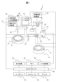
- FIG. 1 is a system block diagram showing the entirety of an automatic analyzer capable of performing blood coagulation measurements.
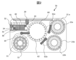
- 1 is a schematic diagram of an automatic analyzer capable of blood coagulation measurements and biochemical measurements. This is an example of an operation sequence of the transfer device. It is a figure showing operation of a transfer device. It is a figure showing operation of a transfer device. It is a figure showing operation of a transfer device. It is a figure showing operation of a transfer device. It is a figure showing operation of a transfer device. It is a figure showing operation of a transfer device. It is a figure showing operation of a transfer device. It is a figure showing operation of a transfer device. It is a figure showing operation of a transfer device. It is a figure showing operation of a transfer device. It is a figure showing operation of a transfer device. It is a figure showing operation of a transfer device. It is a figure showing operation of a transfer device. It is a figure showing operation of a transfer device. It is a figure showing operation of
- FIG. 3 is a diagram showing how a reaction container is used to prevent evaporation of a specimen within the reaction container.
- FIG. 3 is a diagram showing an operation for preventing a decrease in heat retention efficiency of a temperature control mechanism of a reaction container storage section.
- FIG. 3 is a diagram showing an operation for preventing a decrease in heat retention efficiency of a temperature control mechanism of a reaction container storage section.
- FIG. 3 is a diagram showing a temperature control mechanism of a reaction container storage section.
- FIG. 3 is a diagram showing a temperature control mechanism of a reaction container storage section.
- FIG. 3 is a diagram showing a temperature control mechanism of a reaction container storage section.
- FIG. 3 is a diagram showing a sample disc.
- FIG. 3 is a diagram showing a sample disk and a sample dispensing mechanism. It is a figure showing the temperature control mechanism of a sample disk. It is a figure showing the temperature control mechanism of a sample disk. It is a figure showing the temperature control mechanism of a sample disk.
- FIG. 3 is a diagram showing an example of a temperature control area provided on a sample disk. This is an example of a measurement flow when the reaction container storage section has a temperature control mechanism. This is an example of a measurement flow when the sample disk has a temperature control mechanism. This is an example of a temperature control setting screen. This is an example of a temperature log screen.
- FIG. 1 is a system block diagram showing the entirety of an automatic analyzer capable of performing blood coagulation measurement, which is an embodiment of the present invention.
- the automatic analyzer 1 mainly includes a sample dispensing mechanism 10, a sample disk 11, a coagulation reagent dispensing mechanism 20, a reagent disk 21, a reaction container storage section 30, a transfer device 32, a coagulation time measurement It has a section 40 and a computer (control section) 52.
- the transfer device 32 can move between the reaction container storage section 30, the coagulation sample dispensing section 43, and the coagulation time measurement section 40, and can transfer and place the reaction container 31 at a predetermined location.
- the reaction container 31 is a container for mixing a specimen and a reagent and causing the mixed liquid mixture to react.
- the sample disk 11 can be rotated intermittently clockwise and counterclockwise, and a plurality of sample containers 12 containing biological samples such as blood are placed thereon.
- a sample dispensing mechanism 10 is arranged near the sample disk 11.
- the sample dispensing mechanism 10 can rotate clockwise and counterclockwise between the sample disk 11 and the coagulated sample dispensing section 43.
- the sample dispensing mechanism 10 aspirates the sample (specimen) in the sample container 12 using a probe attached to the tip of the sample dispensing mechanism 10, and discharges the sample into the reaction container 31 on the solidified sample dispensing section 43. do.
- a plurality of reagent containers 22 corresponding to the analysis items of the automatic analyzer 1 are placed on the reagent disk 21.
- the coagulation reagent dispensing mechanism 20 sucks the reagent in the reagent container 22 and discharges the reagent into the reaction container 31 .
- a reagent temperature raising mechanism 23 is built in the coagulation reagent dispensing mechanism 20, and the reagent sucked by the coagulation reagent dispensing mechanism 20 is heated to a predetermined temperature (appropriate temperature) by the reagent temperature raising mechanism 23.
- reaction container storage containers 30a for storing reaction containers 31 are installed in the reaction container storage section 30.
- the reaction container storage container 30a is provided with a large number of through holes (reaction container storage positions), and the reaction containers 31 are inserted into these through holes.
- the coagulated sample dispensing section 43 is provided with a recess for placing the reaction container 31, and the reaction container 31 is inserted into this recess.
- the coagulation time measurement section 40 includes a coagulation time detection section 41 provided with a recess in which the reaction vessel 31 is placed.
- the light source 42 irradiates light onto the reaction container 31 placed on the coagulation time detection section 41 .
- the light emitted from the light source 42 is scattered within the reaction vessel 31, and this scattered light is received by a photodiode provided in the coagulation time detection section 41.
- the analog signal of the measured scattered light is input to the A/D converter 56.
- the clotting time is measured based on the digital signal output from the A/D converter. In this manner, the coagulation time of the liquid mixture in the reaction vessel 31 placed on the coagulation time measuring section 40 can be measured.
- the computer (control unit) 52 is connected to a sample dispensing control unit 57 , a coagulation reagent dispensing control unit 58 , a transfer device control unit 59 , and an A/D converter 56 via an interface 50 .
- the computer 52 sends commands to each of these control units and controls each operation. That is, the computer 52 can control the transfer device, the dispensing mechanism, etc. via the control section of each mechanism.
- the interface 50 Connected to the interface 50 are a printer 53 for printing, a memory 55 as a storage device, a keyboard 51 for inputting operation commands, etc., and a display device 54 for screen display such as a CRT display or a liquid crystal display.
- the memory 55 is composed of, for example, a hard disk memory or an external memory.
- the memory 55 stores information such as analysis parameters, analysis item requests, calibration results, and analysis results.
- the transfer device 32 transfers the reaction container 31 stored in the reaction container storage section 30 to the coagulated sample dispensing section 43 and places it thereon.
- the sample dispensing mechanism 10 aspirates a specimen to be used for analysis from the sample container 12 on the sample disk 11 and discharges the specimen into the reaction container 31 on the solidified specimen dispensing section 43.
- the reaction container 31 into which the sample has been dispensed is transferred and placed on the coagulation time detection section 41 by the transfer device 32.
- the coagulation reagent dispensing mechanism 20 discharges the reagent into the reaction container 31 on the coagulation time detection section 41, the sample and the reagent are mixed and a blood coagulation reaction is started.
- the reaction vessel 31 above the coagulation time detection section 41 is irradiated with light from the light source 42 .
- the coagulation time measuring section 40 receives this scattered light, and the A/D converted measurement value is taken into the computer 52 through the interface 50.
- the measurement results are output on the printer 53 or the display device 54.
- FIG. 2 is a schematic diagram of an automatic analyzer 1b that is an embodiment of the present invention and includes a blood coagulation measuring section and an absorbance measuring section capable of biochemical measurements. Note that in FIG. 2, the control system and signal processing system are omitted. Mechanisms that are equivalent to those shown in FIG. 1 are given the same reference numerals and redundant explanations will be omitted.
- the automatic analyzer 1b includes a reaction disk 60 equipped with a plurality of reaction cells (second reaction vessels) 62 and reagent dispensing mechanisms 61a and 61b, which are used for biochemical measurements. Commonly used for blood coagulation tests and biochemical tests. Further, in the configuration of FIG.
- the coagulation time measurement section 40 is provided with a plurality of (six in this example) coagulation time detection sections 41.
- reagents for blood coagulation tests can be sucked into the coagulation reagent dispensing mechanism 20 from the reagent disks 21a and 21b via the reaction cell 62, and are efficiently
- the temperature of the reagent can be raised automatically. This is because the reaction cell 62 is kept at about 37 degrees in a constant temperature bath.
- the reaction container storage section 30 of the automatic analyzer 1b includes a temperature control area where the temperature is adjusted to a predetermined temperature, and two reaction container storage containers are installed therein.
- the temperature control region may be the entire reaction container storage section 30 or only a part thereof.
- the reaction container storage container is provided with a large number of through holes (reaction container storage positions) into which reaction containers 31 are inserted, and empty reaction containers 31 used for blood coagulation measurement are placed in advance. Further, the reaction container storage container is removable from the reaction container storage section 30. For example, when the reaction container storage container becomes empty, the operator can remove the empty reaction container storage container from the reaction container storage section 30, and A new reaction container storage container in which the reaction container 31 is previously stored is installed.
- FIG. 3 shows the operation sequence of the transfer device 32 when the operator registers a request for analysis of blood coagulation items and starts the analysis. Each operation of the transfer device 32 in each step is shown in conjunction with FIGS. 4A to 4I.
- the transfer device 32 is stopped with the upper left of the reaction container storage section 30 as the initial position of the transfer device (S01, FIG. 4A).
- the transfer device 32 grasps the empty reaction container 31 placed in the reaction container storage section 30 (S02, FIG. 4B), transfers it to the coagulated sample dispensing section 43, and places it there. (S03, Figure 4C).
- the transfer device 32 moves to the initial position, and the sample dispensing mechanism 10 dispenses a single sample or a plurality of samples into the reaction container 31 on the coagulated sample dispensing section 43 (S04, FIG. 4D).
- the transfer device 32 grasps the reaction container 35 containing the sample on the coagulated sample dispensing section 43 (S05, FIG. 4E), and holds the reaction container 35 containing the sample on the coagulated sample dispensing section 43 (S05, FIG. 4E), (S06, FIG. 4F), and then the transfer device 32 moves to the initial position (S07, FIG. 4G).
- the sample-containing reaction container 35 is placed in the temperature-controlled reaction container storage section 30 and maintained at a predetermined temperature for a predetermined period (incubation). After the reaction container 35 containing the sample to be analyzed in the reaction container 35 has passed a predetermined temperature control period, the transfer device 32 grasps the reaction container 35 containing the sample placed in the reaction container storage section 30, and sets the coagulation time.
- the reaction container 35 containing the sample is transferred and placed on the detection unit 41 (S08, FIG. 4H).
- the transfer device 32 moves to the initial position (S09, FIG. 4I)
- the coagulation reagent dispensing mechanism 20 discharges the reagent into the reaction container 31 on the coagulation time detection section 41, and the coagulation reaction is started.
- the transfer device 32 grasps the reaction container 31 whose photometry has been completed, and the reaction container disposal section 34 discards the reaction container after the measurement.
- the above operations of the transfer device 32 are executed by being controlled by the transfer device control unit 59 from the computer 52 via the interface 50.
- the operation sequence in FIG. 3 shows an example in which the object of incubation is a specimen or a mixed specimen, but there is also a case where the object of incubation is a reagent dispensed into the reaction container 31 or a mixture of a reagent and a specimen.
- the reaction container containing the reagent or the mixture of reagent and specimen is transferred and placed in the temperature-controlled reaction container storage section 30, and is kept for a predetermined temperature-controlled period. Just let it pass.
- the reagent is dispensed by the coagulation reagent dispensing mechanism 20 into the reaction container 31 placed on the coagulation time measuring section 40.
- the coagulation reagent dispensing mechanism 20 sucks the reagent from the reagent disk 21a and discharges it into the reaction container 31 placed on the coagulation time measuring section 40, and the reagent dispensing mechanism 61a (61b) sucks the reagent from the reagent disk 21a (21b).
- the reagent is dispensed into the reaction cell 62 on the reaction disk 60, and further the reagent is dispensed from the reaction cell 62 into the reaction container 31 placed on the coagulation time measurement section 40 by the coagulation reagent dispensing mechanism 20, or the reaction cell 62, the reagent can be dispensed by the sample dispensing mechanism 10 into the reaction container 31 placed on the coagulated sample dispensing section 43.
- the reaction container storage section 30 is provided with a lid mechanism to prevent evaporation of the specimen.
- the reaction container storage section 30 is provided with at least an area used for incubation ( A lid mechanism is provided to cover the incubation area.
- FIG. 5A shows a state in which the storage lid 70 is in the lid standby position
- FIG. 5B shows a state in which the storage lid 70 covers the incubation area.
- an example is shown in which two rows on the left side of the reaction container storage container 30a1 installed on the left side of the storage section are set as the incubation area.
- the sample-containing reaction container 35 transferred to the incubation area of the reaction container storage section 30 by the transfer device 32 is covered by the storage section lid 70, thereby preventing the liquid contained in the reaction container 35 from evaporating. .
- the storage lid 70 is driven by a motor 72.
- the storage section lid 70 is used when the transfer device 32 grasps an empty reaction container 31 on the reaction container storage section 30 or when the transfer device 32 places a reaction container 35 containing a sample on the reaction container storage section 30. , or when the transfer device 32 grips the reaction container 35 containing the sample in the reaction container storage section 30, the motor 72 is driven to store the storage section lid 70 in the lid standby position. When the transfer device 32 leaves the reaction container storage 30, the motor 72 is driven so that the storage lid 70 covers the incubation area.
- a heat insulating material is provided on the surface of the storage lid 70 facing the incubation area of the reaction container storage 30, or the storage lid 70 is heated to be equal to the temperature of the temperature control area of the reaction container storage 30. It is advisable to provide a heating mechanism.
- the drive mechanism for the storage lid 70 is not limited to a motor, and may be driven by a cylinder 73 as shown in FIG. 6. Further, as shown in FIG. 7, instead of providing a drive mechanism exclusively for the storage lid 70, a knob 74 provided on the storage lid 70 is gripped by the transfer device 32, and moved by the power of the transfer device 32. You may let them.
- the transfer device 32 grasps the empty reaction container 31 placed in the reaction container storage container 30a and stacks it on top of the reaction container 35 containing the specimen.
- the sample can also be placed on the plate to prevent evaporation of the sample during incubation.
- the reaction container 31 used as a simple lid may have dew condensation on its outer wall, so to prevent contamination, it is discarded after use.
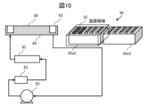
- the temperature control mechanism shown in FIG. 10 extends the flow path of a constant temperature bath 80 for controlling the temperature of the reaction cell 62 on the reaction disk 60 as a heat source of the temperature control mechanism.
- the system water in the constant temperature bath 80 is heated and circulated through a flow path provided with a heater 81, a filtration filter 82, a circulation pump 83, and the like.
- this flow path is extended to the temperature control area of the reaction vessel storage section 30, and the system water in the flow path is used as a heat source.
- the heat source and temperature control for the constant temperature bath 80 can be used, so the temperature control function can be easily realized.
- the temperature control mechanism for the reaction container storage section 30 may be provided independently from the constant temperature bath 80. In this case, the temperature of the reaction container storage section 30 can be controlled to a temperature different from the temperature of the constant temperature bath 80. Furthermore, when heating of the reaction container is not necessary, that is, when incubation is not being performed, temperature control can be omitted. Further, an independent temperature control mechanism may be provided in place of the temperature control mechanism in FIG. 10, or an auxiliary independent temperature control mechanism may be provided in addition to the temperature control mechanism in FIG.
- FIG. 11 shows a first example, in which hot air is used as a heat source.
- the air warmed by the heater 84 is blown into the temperature control area of the reaction container storage section 30 by the blower 85.
- a temperature sensor 86 is provided in the temperature control area, and a heater control unit 87 controls the temperature of the heater 84 based on the temperature of the temperature control area measured by the temperature sensor 86.
- FIG. 12 shows a second example, in which an electric heater 88 is provided in the temperature control area of the reaction vessel storage section 30.
- the electric heater 88 is provided with a temperature sensor 89 such as a thermistor, and the heater control unit 90 controls the temperature of the electric heater 88 based on the temperature detected by the temperature sensor 89.
- FIG. 11 shows a first example, in which hot air is used as a heat source.
- the air warmed by the heater 84 is blown into the temperature control area of the reaction container storage section 30 by the blower 85.
- a temperature sensor 86 is provided in the
- the electric heater 88 is arranged on the side surface of the reaction container storage container 30a1, it may be provided on the bottom surface side, or on both the side surface side and the bottom surface side. Note that the control by the heater control section can also be performed by the computer (control section) 52.
- the reaction container storage container 30a is provided with a through hole that is a storage position for the reaction container. Therefore, when controlling the temperature of a part of the reaction container storage section 30, even if the temperature control area is heated, the warmed air inside the reaction container storage container 30a escapes from the through hole, reducing the heat retention efficiency. descend.
- FIG. 9A is an example in which reaction container storage containers 30a1 and 30a2 are placed in the reaction container storage section 30, and the reaction container storage container 30a1 installed on the left side is used as a temperature control area.
- the reaction containers in the right three rows of the reaction container storage containers 30a1 are used, and the inside and outside of the reaction container storage containers 30a1 are electrically connected through the through holes in which the reaction containers are installed, and the warmed air is transferred to the reaction container storage containers 30a1. It leaks from the side. Therefore, as shown in FIG. 9B, the transfer device 32 grasps the empty reaction container 31 placed in the reaction container storage container 30a2 outside the temperature control area of the reaction container storage section 30, and By moving to an empty reaction container storage position in the container storage container 30a1 and placing the reaction container 31 thereon, the through hole can be closed and heat retention efficiency can be maintained.
- a temperature control area is provided on the sample disk.
- This embodiment is the same as the first embodiment except for the position where the temperature control area is provided, and the same components as those in the first embodiment are given the same reference numerals and redundant explanations will be omitted.
- the configuration of the automatic analyzer includes the configuration of the automatic analyzer 1 that can perform blood coagulation measurements as explained in FIG.
- the automatic analyzer 1b may be configured to include the following.
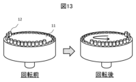
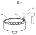
- sample disk 11 The structure of the sample disk is the same as in Example 1. As shown in FIG. 13, the sample disk 11 can be rotated intermittently clockwise and counterclockwise, and a plurality of sample containers 12 containing biological samples such as blood are placed on the sample disk 11. Further, as shown in FIG. 14, a sample dispensing mechanism 10 is arranged near the sample disk 11.
- the sample dispensing mechanism 10 aspirates a sample (specimen) in a sample container 12 placed on a sample disk 11 using a probe attached to the tip of the sample dispensing mechanism 10, and then aspirates the sample (specimen) in a sample container 12 placed on a sample disk 11. Discharge into empty sample container 12.
- the sample dispensing mechanism 10 aspirates the sample (specimen) in the sample container 12 placed on the sample disk 11 using a probe attached to the tip of the sample dispensing mechanism 10 and transfers it to the reaction disk 60. It is discharged into the reaction cell 62 provided or into the reaction container 31 on the coagulated sample dispensing section 43.
- the sample disk 11 of the automatic analyzer 1 (1b) includes a temperature control area where the temperature of the sample disk 11 is adjusted to a predetermined temperature.
- the temperature control area may be provided on the entire sample disk 11 or may be provided on a part of the sample disk 11.
- the object of incubation on the sample disk 11 is the sample or mixed sample in the sample container 12 placed on the sample disk 11, or the sample or mixed sample discharged by the sample dispensing mechanism 10.
- a reagent or a mixture of a reagent and a specimen may be the subject of incubation.
- the sample container 12 containing the reagent or the mixture of the reagent and the specimen may be heated for a predetermined temperature-controlled period using the temperature-controlled sample disk 11.
- the temperature control mechanism shown in FIG. 15 extends the flow path of a constant temperature bath 80 for controlling the temperature of the reaction cell 62 on the reaction disk 60 as a heat source of the temperature control mechanism.
- the system water in the constant temperature bath 80 is heated and circulated through a flow path provided with a heater 81, a filtration filter 82, a circulation pump 83, and the like.
- this flow path is extended to the temperature control area of the sample disk 11, and the system water in the flow path is used as a heat source.
- the heat source and temperature control for the constant temperature bath 80 can be used, so the temperature control function can be easily realized.
- the temperature control mechanism for the sample disk 11 may be provided independently from the constant temperature bath 80.
- an independent temperature control mechanism may be provided in place of the temperature control mechanism in FIG. 15, or an auxiliary independent temperature control mechanism may be provided in addition to the temperature control mechanism in FIG.
- FIG. 16 shows a first example, in which warm air is used as a heat source. Air warmed by the heater 161 is blown to the temperature control area of the sample disk 11 by the blower 162. A temperature sensor 163 is provided in the temperature control area, and the heater control unit 164 controls the temperature of the heater 161 based on the temperature of the temperature control area measured by the temperature sensor 163.
- FIG. 17 shows a second example, in which an electric heater 171 is provided in the temperature control area of the sample disk 11.
- the electric heater 171 is provided with a temperature sensor 172 such as a thermistor, and the heater control unit 173 controls the temperature of the electric heater 171 based on the temperature detected by the temperature sensor 172.
- the control by the heater control section 173 can also be performed by the computer (control section) 52.
- a heater control unit 173 is provided for each temperature control area, but a single heater control unit 173 may control a plurality of electric heaters 171 and a plurality of temperature sensors 172 provided in a plurality of temperature control areas. Good too.
- the wires may be wired using a slip ring.
- the temperature control area may be provided in a part of the sample disk 11 or may be provided in the entire sample disk 11. Further, one or more temperature control areas may be provided in the sample disk 11, and when a plurality of temperature control areas are provided, the size of the area may be changed for each temperature control area. Further, when a plurality of temperature control regions are provided, the temperature may be changed for each temperature control region.
- the sample disk 11 shown in FIG. 17 is an example in which four temperature control areas A to D are provided in a part of the sample disk 11.
- a temperature sensor 172 is provided to the electric heater 171 in each temperature control area, and is controlled by a heater control section 173. Further, in the temperature control regions A to C, the temperature is controlled by an electric heater 171, whereas in the temperature control region D, a Peltier element 174 is used as a heat source.
- a Peltier element it is possible to not only heat the specimen but also to cool it, making it possible to use part of the reagent disk as a refrigerator for storing the specimen.
- quality control samples and calibrators used for calibration are stored.
- calibration for precision control can be automatically executed at any timing during analysis operation, and at the same time, incubation at high temperatures is possible.
- a closed space is formed in each temperature control area and a heat insulating material is provided to surround the space in order to control the temperature in each temperature control area.
- normal plasma was added to the test plasma as a specimen, and the mixture was prepared so that the ratio of normal plasma was in multiple patterns (0, 10, 20, 50, 80, 90, 100%).
- Prepare mixed plasma The degree of correction of the blood coagulation time of the test plasma by the addition of normal plasma is determined by creating a graph plotting the relationship between the measurement result (blood coagulation time) and the proportion of normal plasma.
- the APTT prolongation is corrected by addition of normal plasma and shows a downward convex pattern.
- APTT prolongation is difficult to correct even when normal plasma is added, and an upwardly convex pattern is exhibited.
- reaction immediately after mixing does not clearly show an upwardly convex shape;
- delayed reaction The reaction after incubation for a certain period of time (hereinafter referred to as delayed reaction) may take on an upwardly convex shape. Therefore, it is recommended that cross-mixing tests measure both immediate and delayed responses.
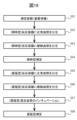
- the automatic analyzer 1 (1b) accepts a request for a cross-mixing test (S11).
- steps from sample preparation to analysis for immediate measurement to measure an immediate reaction are performed (S12 to S14).
- normal plasma is aspirated by the sample dispensing mechanism 10 from the sample container 12 containing normal plasma placed on the sample disk 11, and the empty space is transferred from the reaction container storage container to the coagulation sample dispensing section 43. Normal plasma is discharged into the reaction container 31 of. At this time, the necessary amount of mixed plasma and normal plasma are discharged (S12).
- the sample dispensing mechanism 10 aspirates the test plasma from the sample container 12 containing the test plasma placed on the sample disk 11, and transfers the test plasma to the reaction container 31 into which the normal plasma was discharged in step S12.
- the test plasma is discharged so that the mixed plasma has a predetermined ratio of the test plasma (S13).
- the reaction container 31 containing the mixed plasma is transferred to the coagulation time measuring section 40 by the transfer device 32, and the light source 42 irradiates the reaction container 31 containing the mixed plasma prepared for immediate measurement.
- the coagulation time detection unit 41 detects the light scattered within the reaction vessel 31 (S14).
- steps from sample preparation to analysis for delayed measurement to measure delayed reactions are performed (S15 to S18). Similar to the instant measurement, normal plasma is aspirated by the sample dispensing mechanism 10 from the sample container 12 containing normal plasma placed on the sample disk 11, and is transferred from the reaction container storage container to the coagulated sample dispensing section 43. Normal plasma is discharged into the transferred empty reaction container 31. At this time, the necessary amount of mixed plasma and normal plasma are discharged (S15). Next, the sample dispensing mechanism 10 aspirates the test plasma from the sample container 12 containing the test plasma placed on the sample disk 11, and transfers the test plasma to the reaction container 31 into which the normal plasma was discharged in step S15.
- the test plasma is discharged so that the mixed plasma has a predetermined ratio of the test plasma (S16).
- the mixed plasma is incubated at 37°C for a certain period of time. Therefore, the reaction container 31 in which mixed plasma has been prepared is transferred to the reaction container storage section 30 equipped with a temperature control mechanism using the transfer device 32, and the reaction container 31 is installed in the reaction container storage container. As a result, the mixed plasma in the reaction container 31 is incubated (S17).
- a delayed measurement is performed.
- delayed measurement may be performed using an instruction from the user as a trigger, although this requires a response from the user. In this case, the control unit 52 may notify that the required time for incubation has elapsed.
- the reaction container 31 that has been incubated is transferred from the reaction container storage section 30 to the coagulation time measurement section 40 by the transfer device 32, and the reaction container 31 containing the mixed plasma that has been prepared for delayed measurement and has been incubated. is irradiated with light by the light source 42, and the light scattered within the reaction vessel 31 is detected by the coagulation time detection unit 41 (S18).
- mixed plasma for immediate type measurement is prepared and immediate reaction measurement is performed, and then mixed plasma for delayed type measurement is prepared.
- the present invention is not limited to this, and mixed plasma for delayed measurement may be prepared at the same time as mixed plasma for immediate measurement.
- the automatic analyzer 1 (1b) accepts a request for a cross-mixing test (S21).
- S21 When incubating with the sample disk 11, mixed plasma for immediate and delayed measurements are prepared in the same container.
- the sample dispensing mechanism 10 aspirates normal plasma from the sample container 12 containing normal plasma placed on the sample disk 11 and transfers it to the empty sample container 12 placed on the sample disk 11 for time-based measurement. and discharge normal plasma for delayed measurements. At this time, normal plasma is discharged into the empty sample containers 12 for the required amount of mixed plasma (S22).
- the sample dispensing mechanism 10 sucks the test plasma from the sample container 12 containing the test plasma placed on the sample disk 11, and in step S22, the test plasma is sucked into the sample container 12 into which the normal plasma was discharged.
- the test plasma is discharged so that the mixed plasma has a predetermined ratio of the test plasma (S23).
- the mixed plasma prepared in the sample container 12 is aspirated from the sample container 12 by the sample dispensing mechanism 10 and discharged from the reaction container storage container into the empty reaction container 31 transferred to the coagulation sample dispensing section 43 (S24). .
- the reaction container 31 in which the mixed plasma has been discharged is transferred to the coagulation time measuring section 40 by the transfer device 32, and the light source 42 irradiates the reaction container 31 with light, and the light scattered within the reaction container 31 is coagulated.
- the time detection section 41 detects it (S25).
- the temperature of the sample container 12 containing the remaining mixed plasma is directly controlled using the sample disk 11, and the mixed plasma in the sample container 12 is incubated (S26). Temperature control on the sample disk 11 cannot be performed by the transfer mechanism or the user to the temperature control area whose temperature has been previously adjusted to 37°C, even if the temperature control of the temperature control area is started at the temperature control timing of the mixed plasma for delayed measurement.
- the sample container 12 may also be installed manually. When the incubation of the mixed plasma is completed, the incubated mixed plasma is aspirated from the sample container 12 by the sample dispensing mechanism 10 and transferred from the reaction container storage container 30a to the coagulation sample dispensing section 43 for measurement.
- Step S27 can be performed automatically after incubation without requiring any user intervention by the control unit 52 detecting that incubation has been performed for a certain period of time.
- step S27 may be performed using an instruction from the user as a trigger, although a response from the user is required. In this case, the control unit 52 may notify that the required time for incubation has elapsed.
- the reaction container 31 in which the mixed plasma has been discharged is transferred to the coagulation time measuring section 40 by the transfer device 32, and the light source 42 irradiates the reaction container 31 containing the mixed plasma for delayed measurement with light. , the light scattered within the reaction vessel 31 is detected by the coagulation time detection unit 41 (S28).
- a graph of immediate measurement and delayed measurement is created using the measurement results according to the flow of FIG. 19 or 20, and the user determines the cause of the delay from the created graph.
- the mixed plasma for immediate measurement and the mixed plasma for delayed measurement are prepared in separate containers.
- the mixed plasma for delayed type measurement are Samples can be prepared in one sample container 12 at once. Therefore, the same specimen can be used for both the immediate type and the delayed type. That is, since it is not affected by the dispensing error of the sample dispensing mechanism 10, it is possible to more accurately compare the immediate type and delayed type measurement results.
- mixed plasma for delayed type measurement and mixed plasma for delayed type measurement can be prepared in separate sample containers 12 and measured. is possible.
- the mixed plasma when incubating mixed plasma for delayed measurement in the reaction container storage section 30, the mixed plasma is prepared directly in the reaction container 31.
- the mixed plasma when incubating mixed plasma for delayed measurement in the sample disk 11, the mixed plasma is once prepared in the sample container 12, and then the prepared mixed plasma is dispensed into the reaction container 31. Therefore, when controlling the temperature using the sample disk 11, more dispensing operations are required per time than when controlling the temperature using the reaction container storage section 30, and the required amount of sample increases. That is, when the reaction container storage section 30 is provided with a temperature control mechanism (Example 1), cross-mixing analysis can be performed with a smaller amount of sample than when the temperature is controlled using the sample disk 11.
- FIG. 21 shows an example of a temperature control setting screen displayed on the display device 54.
- the setting screen includes a schematic diagram 211 of a sample disk divided into areas, a temperature setting section 212 for inputting a set temperature for each area, and a setting for which period temperature control is to be performed at the temperature set in the temperature setting section 212. It has a control setting section 213.
- the temperature control period and set temperature can be arbitrarily set for each area, and can be set according to the usage status of the automatic analyzer 1 (1b) by the user. You can also check the temperature control position, temperature, or elapsed incubation time from this screen.
- the area number of the sample disk schematic diagram 211 should be displayed on the sample disk 11. It is also desirable that the position number of the sample container 12 displayed on the sample disk 11 is also displayed on the sample disk schematic diagram 211.
- FIG. 22 is an example of a display screen when area B is selected. Since temperature logs may be used as evidence of experimental results, pressing the CSV output button 221 allows temperature log data to be output. Furthermore, by clicking the area selection button 222, temperature log data for each area can be switched and displayed without returning to the setting screen (FIG. 21).
- FIG. 21 shows an example of a setting screen when a temperature control area is set over the entire sample disk
- the setting screen is displayed in accordance with the actual temperature control area.
- the temperature setting section 212 and control setting section 213 are also only those corresponding to area A.
- the temperature control area is provided only in a part of the sample disk
- an area is set in the sample disk schematic diagram 211 where the temperature control area is provided, and the temperature setting corresponding to the set area is set.
- a section 212 and a control setting section 213 are displayed.
- the temperature log shown in FIG. 22 may be displayed. .
- the present invention is not limited to the embodiments described above, and includes various modifications.
- the above-described embodiments and modifications are described in detail to make the present invention easier to understand, and the present invention is not necessarily limited to having all the configurations described.
- Clotting time Detection unit 42...Light source, 43...Coagulation sample dispensing unit, 50...Interface, 51...Keyboard, 52...Computer (control unit), 53...Printer, 54...Display device, 55...Memory, 56...A/D conversion Machine, 57... Sample dispensing control unit, 58... Coagulation reagent dispensing control unit, 59... Transfer device control unit, 60... Reaction disk, 61... Reagent dispensing mechanism, 62...
- Reaction cell (second reaction container) , 70...Storage lid, 71...Slide rail, 72...Motor, 73...Cylinder, 74...Knob, 80...Thermostat, 81...Heater, 82...Filter filter, 83...Circulation pump, 84, 161...Heater, 85 , 162... Blower, 86, 163... Temperature sensor, 87, 164... Heater control unit, 88, 171a, 171b, 171c... Electric heater, 89, 172a, 172b, 172c, 172d...
- Temperature sensor 90, 173a, 173b, 173c, 173d...Heater control section, 174...Peltier element, 211: Sample disk schematic diagram, 212: Temperature setting section, 213: Control setting section, 221: CSV output button, 222: Area selection button.
Landscapes
- Chemical & Material Sciences (AREA)
- Physics & Mathematics (AREA)
- Health & Medical Sciences (AREA)
- Life Sciences & Earth Sciences (AREA)
- Analytical Chemistry (AREA)
- Biochemistry (AREA)
- General Health & Medical Sciences (AREA)
- General Physics & Mathematics (AREA)
- Immunology (AREA)
- Pathology (AREA)
- Chemical Kinetics & Catalysis (AREA)
- Automatic Analysis And Handling Materials Therefor (AREA)
Priority Applications (4)
| Application Number | Priority Date | Filing Date | Title |
|---|---|---|---|
| CN202380032252.XA CN118974564A (zh) | 2022-04-07 | 2023-04-06 | 自动分析装置 |
| US18/850,600 US20250027964A1 (en) | 2022-04-07 | 2023-04-06 | Automatic analysis device |
| EP23784806.4A EP4506694A1 (en) | 2022-04-07 | 2023-04-06 | Automatic analysis device |
| JP2024514315A JP7836386B2 (ja) | 2022-04-07 | 2023-04-06 | 自動分析装置 |
Applications Claiming Priority (2)
| Application Number | Priority Date | Filing Date | Title |
|---|---|---|---|
| JP2022063923 | 2022-04-07 | ||
| JP2022-063923 | 2022-04-07 |
Publications (1)
| Publication Number | Publication Date |
|---|---|
| WO2023195522A1 true WO2023195522A1 (ja) | 2023-10-12 |
Family
ID=88243090
Family Applications (1)
| Application Number | Title | Priority Date | Filing Date |
|---|---|---|---|
| PCT/JP2023/014261 Ceased WO2023195522A1 (ja) | 2022-04-07 | 2023-04-06 | 自動分析装置 |
Country Status (5)
| Country | Link |
|---|---|
| US (1) | US20250027964A1 (https=) |
| EP (1) | EP4506694A1 (https=) |
| JP (1) | JP7836386B2 (https=) |
| CN (1) | CN118974564A (https=) |
| WO (1) | WO2023195522A1 (https=) |
Citations (5)
| Publication number | Priority date | Publication date | Assignee | Title |
|---|---|---|---|---|
| JP2007017403A (ja) * | 2005-07-11 | 2007-01-25 | Shimadzu Corp | 試料恒温装置 |
| JP2011232212A (ja) * | 2010-04-28 | 2011-11-17 | Hitachi High-Technologies Corp | 自動分析装置 |
| JP2014238346A (ja) * | 2013-06-10 | 2014-12-18 | 株式会社日立ハイテクノロジーズ | 自動分析装置 |
| WO2020100643A1 (ja) * | 2018-11-14 | 2020-05-22 | 積水メディカル株式会社 | 自動分析方法および装置並びに検体ラック |
| JP2021099360A (ja) * | 2015-03-20 | 2021-07-01 | 株式会社日立ハイテク | 自動分析装置及び自動分析方法 |
-
2023
- 2023-04-06 US US18/850,600 patent/US20250027964A1/en active Pending
- 2023-04-06 JP JP2024514315A patent/JP7836386B2/ja active Active
- 2023-04-06 WO PCT/JP2023/014261 patent/WO2023195522A1/ja not_active Ceased
- 2023-04-06 EP EP23784806.4A patent/EP4506694A1/en active Pending
- 2023-04-06 CN CN202380032252.XA patent/CN118974564A/zh active Pending
Patent Citations (5)
| Publication number | Priority date | Publication date | Assignee | Title |
|---|---|---|---|---|
| JP2007017403A (ja) * | 2005-07-11 | 2007-01-25 | Shimadzu Corp | 試料恒温装置 |
| JP2011232212A (ja) * | 2010-04-28 | 2011-11-17 | Hitachi High-Technologies Corp | 自動分析装置 |
| JP2014238346A (ja) * | 2013-06-10 | 2014-12-18 | 株式会社日立ハイテクノロジーズ | 自動分析装置 |
| JP2021099360A (ja) * | 2015-03-20 | 2021-07-01 | 株式会社日立ハイテク | 自動分析装置及び自動分析方法 |
| WO2020100643A1 (ja) * | 2018-11-14 | 2020-05-22 | 積水メディカル株式会社 | 自動分析方法および装置並びに検体ラック |
Also Published As
| Publication number | Publication date |
|---|---|
| EP4506694A1 (en) | 2025-02-12 |
| JP7836386B2 (ja) | 2026-03-26 |
| CN118974564A (zh) | 2024-11-15 |
| JPWO2023195522A1 (https=) | 2023-10-12 |
| US20250027964A1 (en) | 2025-01-23 |
Similar Documents
| Publication | Publication Date | Title |
|---|---|---|
| JP7602524B2 (ja) | 自動分析装置及び自動分析方法 | |
| US20240272186A1 (en) | Automatic analyzer | |
| JP2561509B2 (ja) | 試験片を用いる生化学分析方法及び装置 | |
| JP4434357B2 (ja) | 自動分析装置 | |
| JP6549329B2 (ja) | 自動分析装置 | |
| EP3621738B1 (en) | Methods and apparatus for rapid heating of biological specimens | |
| JPWO2017122455A1 (ja) | 自動分析装置及びその制御方法 | |
| JP6725174B2 (ja) | 自動分析装置 | |
| JP3849343B2 (ja) | 自動分析装置 | |
| JP2012159392A (ja) | 分析装置及び分析方法 | |
| JP7038221B2 (ja) | サーマルサイクラーおよびそれを備えたリアルタイムpcr装置 | |
| JP5097466B2 (ja) | 自動分析装置 | |
| JP6026753B2 (ja) | 自動分析装置 | |
| JP7514185B2 (ja) | 自動分析方法および装置並びに検体ラック | |
| JP5271929B2 (ja) | 自動分析装置 | |
| WO2023195522A1 (ja) | 自動分析装置 | |
| JP3127156U (ja) | 自動分析装置 | |
| WO2018230217A1 (ja) | 自動分析装置 | |
| JP3983872B2 (ja) | 自動分析装置 | |
| JP7844177B2 (ja) | 自動分析装置 | |
| JPS6126861A (ja) | 生化学分析装置 |
Legal Events
| Date | Code | Title | Description |
|---|---|---|---|
| 121 | Ep: the epo has been informed by wipo that ep was designated in this application |
Ref document number: 23784806 Country of ref document: EP Kind code of ref document: A1 |
|
| ENP | Entry into the national phase |
Ref document number: 2024514315 Country of ref document: JP Kind code of ref document: A |
|
| WWE | Wipo information: entry into national phase |
Ref document number: 18850600 Country of ref document: US |
|
| WWE | Wipo information: entry into national phase |
Ref document number: 202380032252.X Country of ref document: CN |
|
| WWE | Wipo information: entry into national phase |
Ref document number: 2023784806 Country of ref document: EP |
|
| NENP | Non-entry into the national phase |
Ref country code: DE |
|
| ENP | Entry into the national phase |
Ref document number: 2023784806 Country of ref document: EP Effective date: 20241107 |