WO2023195259A1 - インシュレータ、ステータ、回転電機、および、ステータの製造方法 - Google Patents
インシュレータ、ステータ、回転電機、および、ステータの製造方法 Download PDFInfo
- Publication number
- WO2023195259A1 WO2023195259A1 PCT/JP2023/006350 JP2023006350W WO2023195259A1 WO 2023195259 A1 WO2023195259 A1 WO 2023195259A1 JP 2023006350 W JP2023006350 W JP 2023006350W WO 2023195259 A1 WO2023195259 A1 WO 2023195259A1
- Authority
- WO
- WIPO (PCT)
- Prior art keywords
- insulator
- stator
- connecting portion
- split
- split core
- Prior art date
- Legal status (The legal status is an assumption and is not a legal conclusion. Google has not performed a legal analysis and makes no representation as to the accuracy of the status listed.)
- Ceased
Links
Images














Classifications
-
- H—ELECTRICITY
- H02—GENERATION; CONVERSION OR DISTRIBUTION OF ELECTRIC POWER
- H02K—DYNAMO-ELECTRIC MACHINES
- H02K15/00—Processes or apparatus specially adapted for manufacturing, assembling, maintaining or repairing of dynamo-electric machines
- H02K15/02—Processes or apparatus specially adapted for manufacturing, assembling, maintaining or repairing of dynamo-electric machines of stator or rotor bodies
- H02K15/021—Magnetic cores
- H02K15/022—Magnetic cores with salient poles
-
- H—ELECTRICITY
- H02—GENERATION; CONVERSION OR DISTRIBUTION OF ELECTRIC POWER
- H02K—DYNAMO-ELECTRIC MACHINES
- H02K1/00—Details of the magnetic circuit
- H02K1/06—Details of the magnetic circuit characterised by the shape, form or construction
- H02K1/12—Stationary parts of the magnetic circuit
- H02K1/14—Stator cores with salient poles
- H02K1/146—Stator cores with salient poles consisting of a generally annular yoke with salient poles
- H02K1/148—Sectional cores
-
- H—ELECTRICITY
- H02—GENERATION; CONVERSION OR DISTRIBUTION OF ELECTRIC POWER
- H02K—DYNAMO-ELECTRIC MACHINES
- H02K1/00—Details of the magnetic circuit
- H02K1/06—Details of the magnetic circuit characterised by the shape, form or construction
- H02K1/12—Stationary parts of the magnetic circuit
- H02K1/18—Means for mounting or fastening magnetic stationary parts on to, or to, the stator structures
-
- H—ELECTRICITY
- H02—GENERATION; CONVERSION OR DISTRIBUTION OF ELECTRIC POWER
- H02K—DYNAMO-ELECTRIC MACHINES
- H02K15/00—Processes or apparatus specially adapted for manufacturing, assembling, maintaining or repairing of dynamo-electric machines
- H02K15/08—Forming windings by laying conductors into or around core parts
- H02K15/095—Forming windings by laying conductors into or around core parts by laying conductors around salient poles
-
- H—ELECTRICITY
- H02—GENERATION; CONVERSION OR DISTRIBUTION OF ELECTRIC POWER
- H02K—DYNAMO-ELECTRIC MACHINES
- H02K3/00—Details of windings
- H02K3/32—Windings characterised by the shape, form or construction of the insulation
- H02K3/325—Windings characterised by the shape, form or construction of the insulation for windings on salient poles, such as claw-shaped poles
-
- H—ELECTRICITY
- H02—GENERATION; CONVERSION OR DISTRIBUTION OF ELECTRIC POWER
- H02K—DYNAMO-ELECTRIC MACHINES
- H02K3/00—Details of windings
- H02K3/32—Windings characterised by the shape, form or construction of the insulation
- H02K3/34—Windings characterised by the shape, form or construction of the insulation between conductors or between conductor and core, e.g. slot insulation
-
- H—ELECTRICITY
- H02—GENERATION; CONVERSION OR DISTRIBUTION OF ELECTRIC POWER
- H02K—DYNAMO-ELECTRIC MACHINES
- H02K3/00—Details of windings
- H02K3/46—Fastening of windings on the stator or rotor structure
-
- H—ELECTRICITY
- H02—GENERATION; CONVERSION OR DISTRIBUTION OF ELECTRIC POWER
- H02K—DYNAMO-ELECTRIC MACHINES
- H02K3/00—Details of windings
- H02K3/46—Fastening of windings on the stator or rotor structure
- H02K3/52—Fastening salient pole windings or connections thereto
- H02K3/521—Fastening salient pole windings or connections thereto applicable to stators only
- H02K3/522—Fastening salient pole windings or connections thereto applicable to stators only for generally annular cores with salient poles
-
- H—ELECTRICITY
- H02—GENERATION; CONVERSION OR DISTRIBUTION OF ELECTRIC POWER
- H02K—DYNAMO-ELECTRIC MACHINES
- H02K2203/00—Specific aspects not provided for in the other groups of this subclass relating to the windings
- H02K2203/12—Machines characterised by the bobbins for supporting the windings
Definitions
- the present application relates to an insulator, a stator, a rotating electrical machine, and a method for manufacturing a stator.
- a stator for a conventional rotating electric machine has been disclosed in which core pieces divided into teeth are connected to each other so as to be bendable in a direction perpendicular to the axis (for example, see Patent Document 1 and Patent Document 2). . Adjacent teeth in the stator are close to each other on the inside in the radial direction, but according to the above configuration, by changing the angle of the connecting part so that the teeth are located on the outer diameter side, they interfere with the adjacent core pieces. The space factor of the coil can be improved.
- Patent Document 1 it is necessary to prepare two types of laminated steel plates in order to engage the laminated steel plates of adjacent core pieces at the connecting part, and it is necessary to draw and swage for the connection, etc.
- Patent Document 2 a mechanism for inserting and removing in the axial direction is provided for connection and rotation, but when the teeth are directed outward, it is necessary to prevent displacement in the axial direction after connection. , it is necessary to prepare a holding mechanism, etc., which makes the manufacturing equipment complicated and increases the cost.Furthermore, there are problems in that the manufacturing process becomes complicated.
- the present application discloses a technology for solving the above-mentioned problems, and aims to provide an insulator, a stator, a rotating electric machine, and a method for manufacturing a stator, which is low cost and has a simple manufacturing process. shall be.
- the insulator disclosed in this application is The stator of a rotating electrical machine has a plurality of split coil winding bodies arranged in a ring shape, each having a split core, an insulator installed on the split core, and a coil wound around the split core via the insulator.
- An insulator a first connecting portion connected to the other circumferentially adjacent insulator at one end in the radially outer circumferential direction; a second connecting portion connected to the first connecting portion of another circumferentially adjacent insulator at the other circumferentially outer end in the radial direction;
- the first connecting portion and the second connecting portion are configured with a snap-fit mechanism using elastic deformation,
- a pair of circumferentially adjacent insulators connected at the first connecting portion and the second connecting portion are mutually arranged at the center of rotation in the axial direction of the first connecting portion and the second connecting portion. formed to be rotatable, The rotation center axis is located radially inward from the radially outer peripheral surface of the split core.
- the stator disclosed in this application is The stator using the insulator described above,
- the split core has a yoke portion extending in the circumferential direction, and teeth portions protruding radially inward from an inner circumferential surface on the radially inner side of the yoke portion,
- One circumferential end of the yoke portion is formed in a convex shape
- the other end in the circumferential direction of the yoke portion is formed in a concave shape
- the convex shape and the concave shape have curved surfaces formed with the same radius of curvature.
- the rotating electrical machine disclosed in this application is The stator described above,
- the rotor is provided with a rotor disposed radially opposite to the stator with a gap interposed therebetween.
- the method for manufacturing a stator disclosed in this application includes: In the method for manufacturing a stator described above, After connecting the first connecting portion and the second connecting portion of the circumferentially adjacent divided cores in which a plurality of the insulators are installed, a number of which forms the stator, a flyer arm connects the teeth through the insulators.
- the coil is formed by continuously winding the magnet wire around the section.
- stator According to the insulator, stator, rotating electric machine, and method for manufacturing a stator disclosed in the present application, It is possible to obtain an insulator, a stator, a rotating electric machine, and a method for manufacturing a stator that is low cost and has a simple manufacturing process.
- FIG. 3 is a plan view showing the configuration of a split core according to the first embodiment.
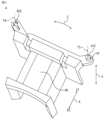
- FIG. 2 is a perspective view showing the configuration of an insulator installed in the split core shown in FIG. 1.
- FIG. 3 is a plan view showing the configuration of the insulator shown in FIG. 2.
- FIG. 3 is a bottom view showing the configuration of the insulator shown in FIG. 2.
- FIG. 3 is a perspective view showing a configuration in which the insulator shown in FIG. 2 is installed in the split core shown in FIG. 1;
- FIG. 6 is a perspective view showing a state in which the insulators of the split core shown in FIG. 5 are connected in the circumferential direction.
- FIG. 7 is a plan view showing a state in which a coil is formed through the insulator of the split core shown in FIG. 6.
- FIG. 7 is a plan view showing a state in which a coil is formed through the insulator of the split core shown in FIG. 6.
- FIG. 6 is a plan view showing a state in which a coil is formed via the insulator of the split core shown in FIG. 5.
- FIG. FIG. 9 is a plan view showing a configuration in which the split coil winding bodies formed in FIGS. 7 to 9 are arranged in an annular shape.
- FIG. 11 is an enlarged plan view of a portion of the divided coil winding body shown in FIG. 10 arranged in an annular shape.
- FIG. 12 is a plan view showing a method of annularly arranging the split coil winding bodies shown in FIG. 11;
- FIG. 11 is a perspective view showing the structure of a stator in which the annularly arranged split coil winding body shown in FIG. 10 is molded.
- 14 is a cross-sectional view showing the configuration of a rotating electric machine using the stator shown in FIG. 13.
- FIG. FIG. 11 is a cross-sectional view showing the configuration of a rotating electrical machine using the annularly arranged split coil winding body shown in FIG. 10;
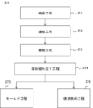
- 15 is a flowchart showing a method of forming the stator shown in FIG. 13 or 14.
- FIG. 15 is a flowchart showing another method of forming the stator shown in FIG. 13 or 14.
- FIG. 15 is a diagram showing another method of forming the stator shown in FIG. 13 or 14.
- FIG. 7 is a plan view showing the configuration of a split core according to a second embodiment.
- FIG. 20 is a perspective view showing the configuration of an insulator installed in the split core shown in FIG. 19.
- FIG. 21 is a perspective view showing a configuration in which the insulator shown in FIG. 20 is installed in the split core shown in FIG. 19.
- FIG. FIG. 22 is a perspective view showing a state in which the insulators of the split core shown in FIG. 21 are connected in the circumferential direction. 22 is a plan view showing a state in which a coil is formed through the insulator of the split core shown in FIG. 21.
- FIG. 22 is a plan view showing a state in which a coil is formed through the insulator of the split core shown in FIG. 21.
- FIG. 22 is a plan view showing a state in which a coil is formed through the insulator of the split core shown in FIG. 21.
- FIG. FIG. 26 is a plan view showing a configuration in which the split coil winding bodies formed in FIGS. 23 to 25 are arranged in an annular manner.
- FIG. 27 is an enlarged plan view of a portion of the annularly arranged split coil winding body shown in FIG. 26;
- FIG. 7 is a perspective view showing the configuration of an insulator installed in a split core according to a third embodiment.
- FIG. 7 is a perspective view showing a state in which split coil wrapping bodies according to Embodiment 3 are connected in the circumferential direction.
- FIG. 7 is a perspective view showing a state in which split coil wrapping bodies according to Embodiment 3 are connected in the circumferential direction.
- 7 is a perspective view showing the configuration of another insulator installed in the split core according to Embodiment 3.
- FIG. 7 is a perspective view showing a state in which another split coil winding body according to Embodiment 3 is connected in the circumferential direction.
- FIG. 7 is a perspective view showing a state in which another split coil winding body according to Embodiment 3 is connected in the circumferential direction.
- FIG. 7 is a plan view showing the state of adjacent divided cores in a comparative example.
- each direction in the rotating electrical machine 100 is referred to as an axial direction Y, a circumferential direction Z, and a radial direction X.
- the axial direction Y is a direction parallel to the shaft 13 (output shaft) of the rotating electrical machine 100
- the circumferential direction Z is the rotating direction of the rotating electrical machine 100
- the radial direction X is the radial direction of the rotating electrical machine 100.
- the description will be made as an outer side X1 in the radial direction X and an inner side X2 in the radial direction X. Therefore, other parts constituting the rotating electric machine 100 will also be explained based on this direction. Further, in other embodiments as well, each direction will be similarly shown and explained.
- FIG. 1 is a plan view showing the configuration of a split core according to the first embodiment.
- FIG. 2 is a perspective view showing the configuration of an insulator installed in the split core shown in FIG. 1.
- FIG. 3 is a plan view showing the configuration of the insulator shown in FIG. 2.
- FIG. 4 is a bottom view showing the configuration of the insulator shown in FIG. 2.
- FIG. 5 is a perspective view showing a configuration in which the insulator shown in FIG. 2 is installed in the split core shown in FIG. 1.
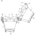
- FIG. 6 is a perspective view showing how the insulators of the split core shown in FIG. 5 are connected in the circumferential direction.
- FIG. 7 is a plan view showing a state in which a coil is formed via the insulator of the split core shown in FIG. 6.
- FIG. 8 is a plan view showing a state in which a coil is formed via the insulator of the split core shown in FIG. 6.
- FIG. 9 is a plan view showing a state in which a coil is formed via the insulator of the split core shown in FIG.
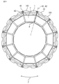
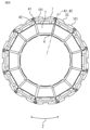
- FIG. 10 is a plan view showing a structure in which the split coil winding bodies formed in FIGS. 7 to 9 are arranged in an annular shape.
- the annular shape indicates an example formed in a circular ring shape.
- FIG. 11 is an enlarged plan view of a portion of the annularly arranged split coil wrapping shown in FIG. 10.
- FIG. 12 is a plan view showing a method of arranging the split coil winding bodies shown in FIG. 11 in an annular shape.
- FIG. 13 is a perspective view showing the structure of a stator in which the annularly arranged split coil wrapping shown in FIG. 10 is molded.
- FIG. 14 is a sectional view showing the configuration of a rotating electrical machine using the stator shown in FIG. 13.
- FIG. 15 is a sectional view showing the configuration of a rotating electric machine using the annularly arranged divided coil winding body shown in FIG. 10.
- FIG. 16 is a flowchart showing a method of forming the stator shown in FIG. 13 or 14.
- FIG. 17 is a flow chart showing another method of forming the stator shown in FIG. 13 or 14.
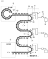
- FIG. 18 is a diagram showing another method of forming the stator shown in FIG. 13 or 14.
- FIG. 34 is a plan view showing the state of adjacent divided cores in a comparative example.
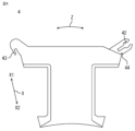
- FIG. 1 is a plan view showing the configuration of the split core 1.
- a divided core 1 is formed by dividing an annular stator 12 of an inner rotor type rotating electric machine 100 (see FIG. 14) into slots in the circumferential direction Z.
- the split core 1 includes a yoke portion 3 extending in the circumferential direction Z, and teeth portions 2 protruding from the inner peripheral surface of the yoke portion 3 on the inside X2 in the radial direction X toward the inside X2 in the radial direction X.
- a first contact portion 31 is formed as a circumferential end surface that abuts against another split core 1 adjacent to one side in the circumferential direction Z.
- a second contact portion 32 is formed as a circumferential end surface that abuts against another split core 1 adjacent to the other split core 1 in the circumferential direction Z.
- the first contact portion 31 and the second contact portion 32 are formed in a planar shape that is a combination of a curved surface and a flat surface.
- the first contact portion 31 is formed in a convex shape protruding in the circumferential direction Z.
- the second contact portion 32 is formed in a concave shape recessed in the circumferential direction Z.
- the curved surface portions of the first contact portion 31 and the second contact portion 32 are formed with a radius of curvature R.
- the center axis of the radius of curvature R of the first contact portion 31 in the axial direction Y is the first center axis T1
- the center axis of the radius of curvature R of the second contact portion 32 in the axial direction Y is the second center axis It is T2.
- the first central axis T1 is on the first virtual plane A1 extending in the axial direction Y at the center of the circumferential direction Z of a pair of split cores 1 adjacent in the circumferential direction Z
- the first central axis T1 is on the second virtual plane A2.
- Two central axes T2 are respectively formed.
- the first center axis T1 of one split core 1 adjacent to the circumferential direction Z coincides with the second center axis T2 of the other split core 1. Furthermore, when the annular stator 12 is assembled, the first abutting portion 31 of one split core 1 and the second abutting portion 32 of the other split core 1 adjacent in the circumferential direction Z are shaped so as to follow each other. It is formed by
- the first central axis T1 and the second central axis T2 are formed at a position X2 inside in the radial direction X from the outer circumferential surface 33 of the split core 1 in the radial direction X. This makes it possible to ensure the thickness of the molded resin portion 6 (see FIGS. 13 and 14), which will be described later, or to prevent interference with the shrink-fit frame 16 (see FIG. 15). Note that the split core 1 does not have a means for joining and holding the split cores together. In this way, since the split core 1 has a simple shape, only one type of mold for the split core 1 needs to be prepared, making it easy to manufacture and at low cost.
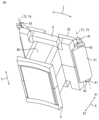
- FIG. 2 is a perspective view showing the configuration of the insulator 4.
- FIG. 3 is a plan view showing the structure of the insulator 4 of FIG. 2 as viewed from the upper side of the paper.
- FIG. 4 is a plan view showing the structure of the insulator 4 of FIG. 2 viewed from the back side of the paper.
- the insulator 4 has a shape that follows the teeth portion 2 of the split core 1 in order to insulate the split core 1 from the coil 7 (see FIG. 7) that will be wound in a later process. It is formed by A winding portion 45 around which the coil 7 is wound is provided.
- the insulator 4 is formed of an insulating material with a low elastic modulus, such as resin.
- a columnar portion 41 as a first connecting portion is formed at one end of the outer side X1 in the radial direction X of the insulator 4 in the circumferential direction Z. Further, at the other end in the circumferential direction Z of the outer side X1 in the radial direction is formed.
- the columnar portion 41 and the opening 42 are formed by a snap-fit mechanism using elastic deformation.
- the columnar portion 41 and the opening 42 are formed with dimensions such that the maximum strain when engaged by the snap fit mechanism does not exceed the destructive strain.
- the columnar part 41 and the opening part 42 are rotatable in the engaged state, and the rotation center axis at this time is as shown in FIG. 2, the columnar part 41 has a first rotation center axis T3, The opening 42 has a second rotation center axis T4. Further, the first rotation center axis T3 is the first center axis T1 of the split core 1 shown in FIG. 1, and the second rotation center axis T4 is the second center axis T2 of the split core 1 shown in FIG. is set to match.
- the columnar part 41 has a claw-shaped first return part 43 formed in the base part. As shown in FIG. 4, the opening 42 has a second bent portion 44 formed in the pedestal portion. The first turned part 43 and the second turned part 44 catch each other when the divided cores 1 are assembled in an annular shape, thereby improving the holding strength of the assembled state in an annular shape.
- FIG. 5 is a perspective view showing a state in which the insulators 4 are assembled to both ends of the split core 1 in the axial direction Y, respectively.
- the first rotation center axis T3 of the columnar part 41 of the insulator 4 at both ends in the axial direction Y is aligned with the first central axis T1 of the split core 1, and the opening 42
- the second rotation center axes T4 are located coaxially with the second center axis T2. Therefore, each rotation center axis T3, T4 is located on the inner side X2 in the radial direction X than the outer peripheral surface 33 on the outer side X1 in the radial direction X of the split core 1.
- the first rotation center axis T3 is located on the inner side of the circumferential direction Z of the split core 1 (the first contact portion 31) (closer to the center side of the teeth portion 2 in the circumferential direction Z, as viewed from the axial direction Y). It is located at a position where it overlaps with the split core 1 when Further, the second rotation center axis T4 is located on the outer side in the circumferential direction Z than the circumferential end surface (second contact portion 32) of the split core 1.
- the circumferential end surface (first contact portion 31) of the split core 1 on the side of the first rotation center axis T3 extends from the first rotation center axis T3 to the outside X1 in the radial direction X, that is, to the outer peripheral surface 33 of the split core 1. is formed of a circular arc surface centered on the first rotation center axis T3. Further, the circumferential end surface (second contact portion 32) of the split core 1 on the second rotation center axis T4 side is formed of an arcuate surface recessed along the arcuate surface.
- the circumferential end faces of the split core 1 on the outside X1 in the radial direction X from the rotation center axes T3 and T4 can be brought into contact with each other without leaving any gaps, ensuring a magnetic path and suppressing the occurrence of magnetic saturation.
- the insulator 4 located above the paper in the axial direction Y has the shape shown in FIGS. 2 to 4, and the insulator 4 located above and below the paper in the axial direction Y has the shape shown in FIGS. It has a mirror-symmetrical shape with the upper insulator 4. Note that this is just an example, and it is also conceivable that the insulators 4 at both ends in the axial direction Y are formed in the same shape.
- FIG. 6 a configuration in which two split cores 1 each having an assembled insulator 4 as shown in FIG. 5 are arranged in the circumferential direction Z will be described using FIG. 6.
- two split cores 1 with insulators 4 assembled are arranged in the circumferential direction Z, and the columnar part 41 of one insulator 4 and the opening 42 of the other insulator 4 are fitted together by a snap fit mechanism. and connect.
- the opening 42 is elastically deformed by the snap-fit mechanism, and the columnar part 41 of the insulator 4 and the opening 42 are engaged with each other at a position coaxial with the first rotation center axis T3 and the second rotation center axis T4.
- the divided core 1 adjacent in the circumferential direction Z moves around the first rotation center axis T3 with respect to the other divided core 1 in the opening direction F1 and the closing direction F2 (as shown in FIG. 10). It is formed so that it can be rotated in the direction in which it is formed into an annular shape. Further, the first contact portion 31 and the second contact portion 32 provided at both ends of the split core 1 in the circumferential direction Z are connected to a first contact portion coaxial with the first rotation center axis T3 and the second rotation center axis T4. Since the split core 1 has a curved surface having the same radius of curvature R around the center axis T1 and the second center axis T2, the split core 1 does not hinder the rotation of the insulator 4.
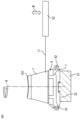
- FIG. 7 shows a state in which the divided core 1 is rotated in the opening direction F1 shown in FIG. 6 about the first rotation center axis T3. Then, the outer circumferential surface 33 of the split core 1 is held by the chuck portion 51 . Next, the magnet wire 71 is supplied through the nozzle 52 from the flyer arm 53 located opposite the teeth portion 2 of the split core 1 around which the magnet wire 71 is wound, and the flyer arm 53 is rotated around the rotation axis Q. By doing so, the magnet wire 71 is wound around the teeth portion 2 of the split core 1 via the insulator 4 to form the coil 7, and the split coil winding body 101 connected in the circumferential direction Z is formed.
- the teeth part 2 of the divided core 1 adjacent to Z is retreated to the outside of the insulator 4 of the teeth part 2 that is being wound.
- the flyer arm 53 can be swung to the left side (to the back) of the tooth portion 2 on the paper in the swiveling direction W, and the coil 7 can be accommodated in the winding space without waste.
- the stator 12 can be made smaller.
- FIG. 7 shows three divided cores 1, one divided core 1 being wound and two divided cores 1 adjacent to each other on both sides in the circumferential direction Z. Only one divided core 1 or two divided cores 1 may be held by the chuck portion 51, or a plurality of divided cores 1 may be continuously connected to the three divided cores 1 and supplied.
- FIG. 8 shows a method of forming the coil 7 by winding the magnet wire 71 around the divided cores 1 connected in the circumferential direction Z, as shown in FIG.
- the divided cores 1 connected in the circumferential direction Z are arranged in a straight line, and the outer circumferential surface 33 of the divided cores 1 is held by the chuck part 51 and is opposed to the teeth part 2 of the divided cores 1.
- the magnet wire 71 is supplied in a direction approximately perpendicular to the nozzle 52 that revolves around the tooth portion 2 of the split core 1 around the rotation axis Q while drawing a rectangular or elliptical locus, and swings in the swing direction W.
- the magnet wire 71 is supplied by the nozzle 52 to form the wound coil 7, and the divided coil winding body 101 connected in the circumferential direction Z is formed.
- this figure shows a diagram in which the magnet wire 71 is wound around three split cores 1 connected in the circumferential direction Z, two or four or more split cores 1 may be held by the chuck part 51.
- FIG. 9 shows a method of forming the coil 7 by winding the magnet wire 71 around the split core 1 before being connected in the circumferential direction Z, as shown in FIG.
- the outer circumferential surface 33 of the single split core 1 is held by the chuck portion 51.
- the chuck part 51 rotates the split core 1 around the rotation axis Q, and the magnet wire 71 is supplied by the nozzle 52 that swings in the swing direction W, is wound to form the coil 7, and is wound in the circumferential direction Z.
- An unconnected split coil winding body 101 is formed.
- FIG. 10 shows an example of 12 slots
- the number of slots is not limited to this, and other slot numbers such as 9 slots can be similarly assembled.
- FIG. 11 is an enlarged view of one part of the first rotation center axis T3 in FIG. 10.
- FIG. 12 shows the same portion as FIG. 11 in a state where the teeth portion 2 is rotated in the opening direction.
- each center axis T1, T2 and each rotation center axis T3, T4 are located on each virtual plane A1, A2 with respect to the divided core 1 adjacent in the circumferential direction Z, and the divided core
- the first abutting part 31 and the second abutting part 32 provided at both ends of the circumferential direction Z of 1, respectively, are connected to the first central axis T1 and the second central axis T1 and the second central axis T4, respectively, which are coaxial with the first central axis T3 and the second central axis T4 of rotation.
- the split coil wrapping body 101 on which the coil 7 is formed rotates around the first rotational central axis T3 and rotates in the circumferential direction Z.
- Adjacent divided coil winding bodies 101 come into close contact with each other at the first contact portion 31 and the second contact portion 32 in the circumferential direction Z.
- a convex first contact portion 31 and a concave second contact portion 32 along the first contact portion 31 are formed at both ends of the yoke portion 3 of the split core 1 in the circumferential direction Z. Therefore, a sufficient cross-sectional area of the magnetic flux path can be ensured, and the stator 12 can be miniaturized.
- the teeth portion 2 is closed in an annular shape from the state shown in FIG. 12 to the state shown in FIG. It deforms and the second barbed part 44 passes through, but once it is in the closed state, the first barbed part 43 is caught and prevents the teeth part 2 from opening easily.
- the first barbed part 43 side is configured to be easily elastically deformed, but the second barbed part 44 instead of the first barbed part 43 should be shaped to be easily elastically deformed, or the first barbed part 43 and the second barbed part 44 can also be formed into shapes that are easy to elastically deform.
- FIG. 13 is a diagram showing a configuration in which the split coil winding body 101 assembled into an annular shape as shown in FIG. 10 is molded with resin.
- the connecting force by the columnar part 41 and the opening part 42 of the insulator 4 is sufficient as long as it can withstand transportation up to the molding process.
- the accuracy of the inner diameter of the stator 12 can be ensured by aligning the split coil winding body 101 (the outer peripheral surface 33 of the split core 1) along the mold with the molding pressure of the resin.
- the columnar part 41 and the opening part 42 (the first connecting part and the second connecting part) of the insulator 4 are located on the inner side X2 in the radial direction X than the outer circumferential surface 33 of the split core 1, the thickness of the molded resin part 6 can be reduced. This allows the resin to flow easily during molding.
- a rotary electric machine 100 is constructed by installing a rotor 11 in which a shaft 13 is installed via a bearing 15 in a bracket 14, and a stator 12 in which a molded resin part 6 is formed on the outer circumferential side of the rotor 11 with a gap therebetween. Ru.
- the stator 12 is formed by press-fitting or shrink-fitting the split coil winding body 101 assembled into an annular shape into the cylindrical frame 16.
- the columnar part 41 and the opening part 42 (the first connecting part and the second connecting part) of the insulator 4 are located on the inner side X2 in the radial direction X than the outer circumferential surface 33 of the split core 1, a simple cylindrical shape It can be press-fitted or shrink-fitted into the frame 16, allowing a simple assembly method to be selected.
- the roundness of the inner diameter can be ensured by making the split coil wrapping bodies 101 come into even contact with each other due to the preload created by the interference of press-fitting or shrink-fitting.
- the other configurations are formed in the same manner as in FIG. 14 shown above.
- the insulator 4 is assembled to the split core 1 as shown in FIG. 5, and an insulation process is performed (step ST1 in FIG. 16).
- the columnar part 41 of the insulator 4 of the split core 1 and the opening 42 (the first connection part and the second connection part) of the split core 1 adjacent to each other in the circumferential direction Z are engaged with each other by a snap fit mechanism to perform a connection process. (Step ST2 in FIG. 16).
- a winding process is performed in which the magnet wire 71 is wound around the split core 1 via the insulator 4 to form the coil 7 and the split coil winding body 101 is formed.
- the divided coil winding bodies 101 connected in the circumferential direction Z are assembled into an annular shape as shown in FIG. 10 (step ST4 in FIG. 16).
- the stator 12 is formed by forming the molded resin portion 6 as shown in FIG. 13 on the annular split coil winding body 101 (step ST5 in FIG. 16).
- the stator 12 is formed by shrink-fitting the frame 16 as shown in FIG. 15 onto the annular split coil winding body 101 as shown in FIG. 10 (step ST6 in FIG. 16).
- the insulator 4 is assembled to the split core 1 as shown in FIG. 5, and an insulation process is performed (step ST11 in FIG. 17).
- a winding process is performed in which the magnet wire 71 is wound around the single split core 1 via the insulator 4 to form the coil 7 and the split coil winding body 101 is formed.
- Step ST12 in FIG. 17 the columnar part 41 of the insulator 4 of the split coil winding body 101 and the opening 42 (first connecting part and second connecting part) of the insulator 4 of the divided coil winding body 101 adjacent in the circumferential direction Z are snapped together. They are engaged by a fit mechanism and a connection process is performed (step ST13 in FIG. 17).
- the divided coil winding bodies 101 connected in the circumferential direction Z are assembled into an annular shape as shown in FIG. 10 (step ST14 in FIG. 17).
- the stator 12 is formed by forming the molded resin portion 6 as shown in FIG. 13 on the annular split coil winding body 101 (step ST15 in FIG. 17).
- the stator 12 is formed by shrink-fitting the frame 16 as shown in FIG. 15 to the annular split coil winding body 101 as shown in FIG. 10 (step ST16 in FIG. 17).
- the process flow shown in FIG. 16 will be obtained, resulting in high production efficiency.
- the method for forming the coil 7 as shown in FIG. 9 space can be secured on the manufacturing line, the winding device can be simplified, and the coil 7 can be manufactured using the process flow shown in FIG. 17.
- FIG. 18 shows an example in which a stator 12 having 12 slots is wound in three phases.
- the divided cores 1 corresponding to more than one stator 12 are connected by the columnar part 41 and the opening 42 (the first connecting part and the second connecting part) of the insulator 4, and the divided cores 1 are wound from the input part 59. 58.
- the flyer arm 53 continuously winds the magnet wire 71.
- the magnet wire 71 is taken out from the wire bobbin 56 in which the magnet wire 71 is stored, and the magnet wire 71 is supplied to the nozzle 52 of the flyer arm 53 after its curl is removed by a tensioner 57.
- the flyer arms 53 are arranged in the number of phases of the stator 12, in this case three phases, and the winding operation section 58 including the flyer arm 53 winds the coil 7 and wires the crossover wire between the coils 7. Only the ON/OFF operation of the chuck portion 51 of the split core 1 around which the magnet wire 71 is wound is performed. Since the magnet wire 71 is cut in the discharge section 55, the magnet wire 71 can be cut outside the cycle time of the winding operation section 58, and the operating rate of the winding device can be maximized. Note that the method for forming the coil 7 using the winding device shown in FIG. 18 can be performed in the same manner in the following embodiments, so a description thereof will be omitted.
- the stator of a rotating electrical machine has a plurality of split coil winding bodies arranged in a ring shape, each having a split core, an insulator installed on the split core, and a coil wound around the split core via the insulator.
- An insulator a first connecting portion connected to the other circumferentially adjacent insulator at one end in the radially outer circumferential direction; a second connecting portion connected to the first connecting portion of another circumferentially adjacent insulator at the other circumferentially outer end in the radial direction;
- the first connecting part and the second connecting part are configured with a snap-fit mechanism using elastic deformation,
- a pair of circumferentially adjacent insulators connected at the first connecting portion and the second connecting portion are mutually arranged at the center of rotation in the axial direction of the first connecting portion and the second connecting portion.
- the split core has a yoke portion extending in the circumferential direction, and teeth portions protruding radially inward from an inner circumferential surface on the radially inner side of the yoke portion, One circumferential end of the yoke portion is formed in a convex shape, The other end in the circumferential direction of the yoke portion is formed in a concave shape, Since the convex shape and the concave shape have curved surfaces formed with the same radius of curvature, Furthermore, according to the rotating electrical machine of Embodiment 1 configured as described above, Since the rotor is provided with a rotor that is arranged to face the stator in the radial direction with a gap therebetween, Since the coil can be formed only by connecting the first connecting part and the second connecting part, the manufacturing process
- the first connecting portion is formed of a columnar portion having a columnar shape
- the second connecting portion is formed of an opening having a columnar surface that engages with the columnar portion, the first connecting portion and the second connecting portion can be easily connected.
- the rotation center axis is formed on a virtual plane extending in the axial direction at the circumferential center of the pair of circumferentially adjacent split cores, The first connecting part and the second connecting part can be easily connected.
- the first connecting portion includes a first return portion that engages with the second connecting portion when the split coil winding body is arranged in an annular manner. Since the second connecting portion includes a second return portion that engages with the first connecting portion when the split coil winding body is arranged in an annular manner, The annular shape of the split coil winding body can be reliably maintained by the engagement of the first return portion and the second return portion.
- the stator of the first embodiment configured as described above, Since the centers of curvature of the convex shape and the concave shape in a cross section perpendicular to the axial direction of the yoke portion coincide with the rotation center axes of the first connecting portion and the second connecting portion, The circumferentially adjacent split cores and insulators can rotate freely around the rotation center axis.
- stator of the first embodiment configured as described above, Since the molded resin part is provided to cover the split coil winding body, The roundness of the stator can be improved.
- the frame is provided with a frame that applies preload to the radially inner side of the outer circumferential surface of the split coil winding body arranged in an annular manner, The roundness of the stator can be improved.
- a flyer arm After connecting the first connecting portion and the second connecting portion of the circumferentially adjacent divided cores in which a plurality of the insulators are installed, a number of which forms the stator, a flyer arm connects the teeth through the insulators. Since the coil is formed by continuously winding the magnet wire around the Magnet wire can be efficiently wound around multiple split cores via insulators.
- One of the rotation center shafts is located circumferentially inner than the circumferential end surface of the split core, Since the other rotation center axis is located on the outer side in the circumferential direction than the circumferential end surface of the split core, The circumferential end surfaces of the split cores radially outside each rotational center axis can be brought into contact with each other without leaving a gap, thereby ensuring a magnetic path and suppressing the occurrence of magnetic saturation.
- FIG. 19 is a plan view showing the configuration of a divided core according to the second embodiment.
- FIG. 20 is a perspective view showing the configuration of an insulator installed in the split core shown in FIG. 19.
- FIG. 21 is a perspective view showing a configuration in which the insulator shown in FIG. 20 is installed in the split core shown in FIG. 19.
- FIG. 22 is a plan view showing the configuration of a split coil winding body connected in the circumferential direction according to the second embodiment.
- 23 to 25 are diagrams showing a method of manufacturing the split coil wrapping shown in FIG. 22.
- FIG. 26 is a diagram showing a configuration in which the split coil winding bodies shown in FIGS. 23 to 25 are formed into an annular shape.
- FIG. 27 is an enlarged view showing a part of the annularly formed split coil wrapping shown in FIG. 26.
- the same parts as in the first embodiment are designated by the same reference numerals, and the description thereof will be omitted.
- the difference between this second embodiment and the first embodiment described above is the positions of the first center axis T1, the second center axis T2, the first rotation center axis T3, and the second rotation center axis T4. Since the other parts are the same as those in the first embodiment, the parts that are different from the first embodiment will be mainly explained here.
- the first contact portion 31 and the second contact portion 32 provided at both ends of the divided core 1 in the circumferential direction Z are connected to each virtual surface of the divided core 1 adjacent in the circumferential direction Z.
- the width H2 of the yoke portion 3 of the split core 1 in the circumferential direction Z can be made smaller than the width H1 in the first embodiment (see FIG. 1). Therefore, when manufacturing the split core 1 by punching and laminating steel plates, the amount of material used can be reduced and costs can be reduced. Furthermore, when punching is performed, the length of the entire circumference of the split core 1 can be made shorter than in the first embodiment, so the punching load can be suppressed and costs can be reduced.
- the first rotation center axis T31 of the columnar portion 41 and the second rotation center axis T41 of the opening 42 are aligned with the first center axis T11 or the second center axis T21. Since it is formed coaxially with the virtual planes A1 and A2, it is formed to be deviated from each of the virtual planes A1 and A2 compared to FIG. 2 of the first embodiment. Note that although the shapes corresponding to the first turned portion 43 and the second turned portion 44 of the first embodiment are omitted, similar shapes can be added.
- the insulator 4 is assembled to the split core 1.
- the columnar portion 41 and the opening 42 of the insulator 4 of the split core 1 are connected, and the tooth portion 2 is rotated about the first central axis T11 in the opening direction.
- the flyer arm 53 as shown in FIG. And it can be retreated to a position where it does not interfere with the nozzle 52.
- a magnet wire 71 similar to that in FIG. 8 of the first embodiment is wound. can.
- the split coil winding body 101 configured in this manner can be assembled into an annular shape in the same manner as in the first embodiment.
- the same effects as those of the first embodiment can be obtained, and Since the rotation center axis is formed so as to be spaced apart in the circumferential direction from a virtual plane extending in the axial direction at the circumferential center of the pair of circumferentially adjacent split cores, Since the size of the divided cores can be reduced, the cost can be further reduced.
- Embodiment 3 In each of the above embodiments, the shape of the columnar portion 41 is cylindrical, and the shape of the opening 42 is a shape having a cylindrical surface. However, the shape is not limited to this. Instead, in the third embodiment, the columnar portion 411 or the columnar portion 412 of the insulator 4 is formed in a polygonal column shape or a columnar shape with unevenness. Therefore, the inner surface of the opening 421 or 422 along the columnar portion 411 or 412 is formed of a polygonal columnar surface or a cylindrical surface having unevenness. The configuration other than this is the same as that of each of the embodiments described above, so the description thereof will be omitted as appropriate.
- the columnar portion 411 of the insulator 4 is formed in a polygonal columnar shape, here a hexagonal columnar shape, and the inner surface of the opening 422 along the columnar portion 411 is a polygonal columnar surface, here a hexagonal columnar shape. It is a figure showing the case where it is formed by a surface.
- FIG. 28 is a perspective view showing the configuration of the insulator 4.
- FIGS. 29 and 30 are perspective views showing the structure of the split coil wrapping body 101 in which the columnar part 411 of the insulator 4 and the opening part 421 are connected.
- FIG. 29 is a diagram showing the state when forming the coil 7 of the split coil winding body 101, and FIG.
- FIG. 30 is a diagram showing the state when forming the coil 7 of the split coil winding body 101 into an annular shape after forming the coil 7. It is a figure showing a state. Note that the hexagonal shape is just an example, and other polygonal prism shapes can be similarly constructed and carried out in the same manner.
- FIG. 31 is a perspective view showing the configuration of the insulator 4.
- 32 and 33 are perspective views showing the structure of the split coil wrapping body 101 in which the columnar part 412 of the insulator 4 and the opening part 422 are connected.
- FIG. 32 is a diagram showing the state when forming the coil 7 of the split coil winding body 101
- FIG. 33 is a diagram showing the state when forming the coil 7 of the split coil winding body 101 into an annular shape after forming the coil 7. It is a figure showing a state. Note that the two locations of the unevenness is an example, and other numbers can be similarly configured and carried out in the same manner.
- the insulator 4 and the split core 1 are rotated around the first rotation center axis T3 (second rotation center axis T4), a resistance force is generated due to the polygonal column or the unevenness.
- the dimensions are such that the maximum strain generated in the columnar parts 411, 412 and the openings 421, 422 when rotated with a force exceeding the resistance force does not exceed the breaking strain of the material of the insulator 4.
- the insulator 4 can be rotated around the first central axis T1 by elastically deforming the insulator 4 by applying a force greater than the rotational resistance force, and the rotation is intermittently stopped by the polygonal prism or the unevenness. Since the rotation can be stopped intermittently, the posture of the split coil wrapping body 101 is stabilized during transportation between processes and when assembled into an annular shape.
- the same effects as those of the above embodiments are achieved, and
- the columnar portion of the connecting portion is formed in a polygonal column shape or a column with irregularities added, Since the connection between the columnar part and the opening of the insulator can stop rotating intermittently, the posture of the split coil wrapping body is stabilized during transportation and when assembled into an annular shape, and the manufacturing process can be simplified.
- the stator of a rotating electrical machine has a plurality of split coil winding bodies arranged in a ring shape, each having a split core, an insulator installed on the split core, and a coil wound around the split core via the insulator.
- An insulator a first connecting portion connected to the other circumferentially adjacent insulator at one end in the radially outer circumferential direction; a second connecting portion connected to the first connecting portion of another circumferentially adjacent insulator at the other circumferentially outer end in the radial direction;
- the first connecting portion and the second connecting portion are configured with a snap-fit mechanism using elastic deformation,
- a pair of circumferentially adjacent insulators connected at the first connecting portion and the second connecting portion are mutually arranged at the center of rotation in the axial direction of the first connecting portion and the second connecting portion. formed to be rotatable, The rotation center axis of the insulator is located radially inward from a radially outer circumferential surface of the split core.
- the first connecting portion is formed of a columnar portion having a columnar shape
- the insulator according to supplementary note 1 wherein the second connecting portion is formed of an opening having a columnar surface that engages with the columnar portion.
- the insulator according to appendix 2 wherein the columnar portion of the first connecting portion is formed in a polygonal column shape or a column with irregularities added thereto.
- the first connecting portion includes a first return portion that engages with the second connecting portion when the split coil winding body is arranged in an annular manner.
- the stator using the insulator according to any one of Supplementary Notes 1 to 6, The split core has a yoke portion extending in the circumferential direction, and teeth portions protruding radially inward from an inner circumferential surface on the radially inner side of the yoke portion, One circumferential end of the yoke portion is formed in a convex shape, The other end in the circumferential direction of the yoke portion is formed in a concave shape,
- the stator has curved surfaces in which the convex shape and the concave shape have the same radius of curvature.
Landscapes
- Engineering & Computer Science (AREA)
- Power Engineering (AREA)
- Manufacturing & Machinery (AREA)
- Iron Core Of Rotating Electric Machines (AREA)
- Insulation, Fastening Of Motor, Generator Windings (AREA)
Priority Applications (3)
| Application Number | Priority Date | Filing Date | Title |
|---|---|---|---|
| CN202380031956.5A CN118975104A (zh) | 2022-04-05 | 2023-02-22 | 绝缘体、定子、旋转电机以及定子的制造方法 |
| JP2024514177A JP7774714B2 (ja) | 2022-04-05 | 2023-02-22 | インシュレータ、ステータ、回転電機、および、ステータの製造方法 |
| US18/725,943 US20250119020A1 (en) | 2022-04-05 | 2023-02-22 | Insulator, stator, rotating electric machine, and method for manufacturing stator |
Applications Claiming Priority (2)
| Application Number | Priority Date | Filing Date | Title |
|---|---|---|---|
| JP2022062876 | 2022-04-05 | ||
| JP2022-062876 | 2022-04-05 |
Publications (1)
| Publication Number | Publication Date |
|---|---|
| WO2023195259A1 true WO2023195259A1 (ja) | 2023-10-12 |
Family
ID=88242812
Family Applications (1)
| Application Number | Title | Priority Date | Filing Date |
|---|---|---|---|
| PCT/JP2023/006350 Ceased WO2023195259A1 (ja) | 2022-04-05 | 2023-02-22 | インシュレータ、ステータ、回転電機、および、ステータの製造方法 |
Country Status (4)
| Country | Link |
|---|---|
| US (1) | US20250119020A1 (https=) |
| JP (1) | JP7774714B2 (https=) |
| CN (1) | CN118975104A (https=) |
| WO (1) | WO2023195259A1 (https=) |
Citations (5)
| Publication number | Priority date | Publication date | Assignee | Title |
|---|---|---|---|---|
| JP2002238221A (ja) * | 1998-06-30 | 2002-08-23 | Mitsubishi Electric Corp | 鉄心装置の製造方法 |
| JP2007215272A (ja) * | 2006-02-07 | 2007-08-23 | Asmo Co Ltd | ステータの製造方法及びステータ |
| JP2009017746A (ja) * | 2007-07-09 | 2009-01-22 | Panasonic Corp | ブラシレスdcモータの固定子鉄芯 |
| JP2012075213A (ja) * | 2010-09-28 | 2012-04-12 | Nidec Sankyo Corp | ステータ |
| WO2017104403A1 (ja) * | 2015-12-15 | 2017-06-22 | 三菱電機株式会社 | コアシート、分割積層コアおよび固定子並びに分割積層コアの製造方法 |
Family Cites Families (1)
| Publication number | Priority date | Publication date | Assignee | Title |
|---|---|---|---|---|
| JP5645998B2 (ja) | 2013-04-24 | 2014-12-24 | 三菱電機株式会社 | 回転電機用固定子の製造方法 |
-
2023
- 2023-02-22 CN CN202380031956.5A patent/CN118975104A/zh active Pending
- 2023-02-22 JP JP2024514177A patent/JP7774714B2/ja active Active
- 2023-02-22 WO PCT/JP2023/006350 patent/WO2023195259A1/ja not_active Ceased
- 2023-02-22 US US18/725,943 patent/US20250119020A1/en active Pending
Patent Citations (5)
| Publication number | Priority date | Publication date | Assignee | Title |
|---|---|---|---|---|
| JP2002238221A (ja) * | 1998-06-30 | 2002-08-23 | Mitsubishi Electric Corp | 鉄心装置の製造方法 |
| JP2007215272A (ja) * | 2006-02-07 | 2007-08-23 | Asmo Co Ltd | ステータの製造方法及びステータ |
| JP2009017746A (ja) * | 2007-07-09 | 2009-01-22 | Panasonic Corp | ブラシレスdcモータの固定子鉄芯 |
| JP2012075213A (ja) * | 2010-09-28 | 2012-04-12 | Nidec Sankyo Corp | ステータ |
| WO2017104403A1 (ja) * | 2015-12-15 | 2017-06-22 | 三菱電機株式会社 | コアシート、分割積層コアおよび固定子並びに分割積層コアの製造方法 |
Also Published As
| Publication number | Publication date |
|---|---|
| US20250119020A1 (en) | 2025-04-10 |
| JPWO2023195259A1 (https=) | 2023-10-12 |
| CN118975104A (zh) | 2024-11-15 |
| JP7774714B2 (ja) | 2025-11-21 |
Similar Documents
| Publication | Publication Date | Title |
|---|---|---|
| EP2713479A2 (en) | Split stator core of a rotary electric machine and corresponding manufacturing method | |
| JP6461381B2 (ja) | 回転電機の固定子、回転電機、および、回転電機の固定子の製造方法 | |
| US11411447B2 (en) | Axial gap motor | |
| WO2002084842A1 (fr) | Stator pour moteurs a rotor interne et procede de production | |
| JP2012075213A (ja) | ステータ | |
| JP4502041B2 (ja) | 回転電機の固定子およびその製造方法 | |
| WO2020174817A1 (ja) | 回転電機のステータ、回転電機、回転電機のステータの製造方法、および、回転電機の製造方法 | |
| JP5988915B2 (ja) | 回転電機の積層鉄心および回転電機の積層鉄心の製造方法およびステータおよび回転電機 | |
| WO2022249525A1 (ja) | インシュレーター、ステーター、回転電機、ステーターの製造方法、および回転電機の製造方法 | |
| JP6250149B2 (ja) | 回転電機の電機子鉄心および電機子の製造方法 | |
| WO2019187925A1 (ja) | 回転電機のステータ、回転電機、及び巻枠の製造方法 | |
| JP2014187856A (ja) | ステータコアの絶縁構造及びステータの組付方法 | |
| CN110140280B (zh) | 旋转电机的定子和旋转电机的定子的制造方法 | |
| WO2019235071A1 (ja) | 回転電機の固定子および回転電機 | |
| WO2023195259A1 (ja) | インシュレータ、ステータ、回転電機、および、ステータの製造方法 | |
| JP6843272B2 (ja) | 回転電機の固定子及び回転電機の固定子の製造方法 | |
| JP6811781B2 (ja) | 回転電機のステータ、および、その製造方法 | |
| JP3621894B2 (ja) | 内転型電動機の固定子 | |
| WO2018198562A1 (ja) | 回転電機のステータコア、ステータ、回転電機、流体ポンプ、回転電機のステータコアの製造方法、ステータの製造方法 | |
| JP7449905B2 (ja) | 回転電機 | |
| JP2018107839A (ja) | 回転電機用固定子コア及び固定子、並びに回転電機 | |
| JP5130242B2 (ja) | ステータ | |
| JP7371506B2 (ja) | 電機子の製造方法及び電機子 | |
| WO2019044612A1 (ja) | 電動モータ | |
| JP2005095000A (ja) | 内転型電動機の固定子 |
Legal Events
| Date | Code | Title | Description |
|---|---|---|---|
| 121 | Ep: the epo has been informed by wipo that ep was designated in this application |
Ref document number: 23784552 Country of ref document: EP Kind code of ref document: A1 |
|
| WWE | Wipo information: entry into national phase |
Ref document number: 2024514177 Country of ref document: JP |
|
| WWE | Wipo information: entry into national phase |
Ref document number: 18725943 Country of ref document: US |
|
| WWE | Wipo information: entry into national phase |
Ref document number: 202380031956.5 Country of ref document: CN |
|
| NENP | Non-entry into the national phase |
Ref country code: DE |
|
| 122 | Ep: pct application non-entry in european phase |
Ref document number: 23784552 Country of ref document: EP Kind code of ref document: A1 |
|
| WWP | Wipo information: published in national office |
Ref document number: 18725943 Country of ref document: US |