WO2023195050A1 - 作画支援プログラム、作画支援装置及び作画支援方法 - Google Patents
作画支援プログラム、作画支援装置及び作画支援方法 Download PDFInfo
- Publication number
- WO2023195050A1 WO2023195050A1 PCT/JP2022/017061 JP2022017061W WO2023195050A1 WO 2023195050 A1 WO2023195050 A1 WO 2023195050A1 JP 2022017061 W JP2022017061 W JP 2022017061W WO 2023195050 A1 WO2023195050 A1 WO 2023195050A1
- Authority
- WO
- WIPO (PCT)
- Prior art keywords
- attribute information
- component
- area
- information
- display
- Prior art date
- Legal status (The legal status is an assumption and is not a legal conclusion. Google has not performed a legal analysis and makes no representation as to the accuracy of the status listed.)
- Ceased
Links
Images


Classifications
-
- G—PHYSICS
- G05—CONTROLLING; REGULATING
- G05B—CONTROL OR REGULATING SYSTEMS IN GENERAL; FUNCTIONAL ELEMENTS OF SUCH SYSTEMS; MONITORING OR TESTING ARRANGEMENTS FOR SUCH SYSTEMS OR ELEMENTS
- G05B19/00—Program-control systems
- G05B19/02—Program-control systems electric
- G05B19/04—Program control other than numerical control, i.e. in sequence controllers or logic controllers
- G05B19/05—Programmable logic controllers, e.g. simulating logic interconnections of signals according to ladder diagrams or function charts
- G05B19/056—Programming the PLC
-
- G—PHYSICS
- G06—COMPUTING OR CALCULATING; COUNTING
- G06F—ELECTRIC DIGITAL DATA PROCESSING
- G06F30/00—Computer-aided design [CAD]
- G06F30/10—Geometric CAD
- G06F30/12—Geometric CAD characterised by design entry means specially adapted for CAD, e.g. graphical user interfaces [GUI] specially adapted for CAD
Definitions
- the present disclosure relates to a drawing support program, a drawing support device, and a drawing support method.
- Programmable displays are known that display the status of devices such as programmable logic controllers (PLCs) and sensors, and accept operations on the devices.
- the display screen displayed on the programmable display includes a plurality of parts as images, such as parts that indicate specific functions such as switches and meters, and parts that display data such as text.
- the display screen displayed on such a programmable display is created by a user selecting, arranging, setting, etc. parts on a drawing screen provided by drawing software.
- an image data creation device divides a background image of a display screen displayed on a programmable display into a plurality of rectangular areas, and when an image of a part is placed in the background image, the image of the part is divided into a plurality of rectangular areas.
- a technique has been disclosed in which a rectangular area to be placed is specified and an image of a component is displayed at a position or size corresponding to the size of the specified rectangular area.
- Patent Document 1 when trying to align the display format of multiple parts on the drawing screen, it is necessary to change attribute information indicating the position, size, etc. of the parts one by one. There was a problem of poor efficiency.
- the present disclosure has been made in view of the above circumstances, and provides for efficiently setting attribute information of parts included as images on the display screen in a drawing screen for drawing a display screen displayed on a programmable display device.
- the purpose of the present invention is to provide a drawing support program, a drawing support device, and a drawing support method that enable the drawing support program, drawing support device, and drawing support method.
- the drawing support program for causing a display device to display a drawing screen for drawing a display screen to be displayed on the programmable display;
- Setting means for setting correction information for correcting attribute information of a part included as an image on the display screen and placed within a specified area on the drawing screen, for the specified area. , functioning as a changing unit that changes attribute information of a component placed within the specified area based on the correction information set by the setting unit;
- the display control means includes: The component arranged in the specified area is displayed on the display device based on the attribute information of the component changed by the changing means.
- a drawing support program and drawing support program that can efficiently set attribute information of parts included as an image on a display screen, A support device and a drawing support method can be provided.
- a diagram showing a functional configuration of a drawing support device according to an embodiment A block diagram showing a hardware configuration of a drawing support device according to an embodiment.
- a diagram showing how correction information according to the embodiment is displayed in a window A diagram showing how collection condition information according to an embodiment is displayed in a window Diagram for explaining examples of values of correction information and collection condition information according to the embodiment
- a diagram showing a state before component attribute information is corrected according to an embodiment A diagram illustrating the state after component attribute information according to the embodiment is corrected.
- a diagram showing a state before parts according to an embodiment are collected in an area A diagram showing a state after parts according to an embodiment are collected in a region Flowchart showing change processing according to the embodiment
- a diagram showing how graph components according to a modified example are arranged on the drawing screen Diagram showing the state after multiple regions are automatically generated due to the arrangement of graph parts according to a modified example A diagram showing how a message inquiring about generation of correction information according to a modified example is displayed.
- a diagram showing how correction information related to a modification is displayed in a window
- the drawing support device 100 is a device in which drawing software for drawing a display screen displayed on a programmable display device is installed.
- a user uses the drawing support device 100 to design and draw a display screen.
- the drawing support device 100 transfers the information of the drawing screen drawn by the user and the firmware running on the programmable display to the programmable display, the programmable display displays the drawing screen drawn by the user as a display screen. It becomes possible to do so.
- FIG. 1 shows the functional configuration of the drawing support device 100.
- the drawing support device 100 includes a reception unit 101 that receives information indicating an operation for drawing performed by a user, and a display control unit 102 that causes a display device to display a drawing screen for drawing a display screen. , a storage unit 103 that stores drawing screen information that defines a drawing screen, a setting unit 104 that sets drawing screen information based on information indicating an accepted operation, and a changing unit 105 that changes drawing screen information. , is provided.
- the drawing support device 100 in FIG. 1 has the hardware configuration shown in FIG. 2.
- the drawing support device 100 includes a processor 11 that executes various processes, a main storage unit 12 used as a work area for the processor 11, an auxiliary storage unit 13 that stores various data used in the processing of the processor 11, and an external It has a communication section 14 for communicating with the device, and an input/output interface 15 for connecting an external device.
- the main storage section 12, the auxiliary storage section 13, the communication section 14, and the input/output interface 15 are all connected to the processor 11 via a bus 16.
- the processor 11 includes a CPU (Central Processing Unit).
- the processor 11 implements various functions of the drawing support device 100 by executing programs stored in the auxiliary storage unit 13.
- the main storage unit 12 includes a RAM (Random Access Memory). A program is loaded into the main storage section 12 from the auxiliary storage section 13 .
- the main storage unit 12 is used as a work area for the processor 11.
- the auxiliary storage unit 13 includes a nonvolatile memory represented by EEPROM (Electrically Erasable Programmable Read-Only Memory).
- EEPROM Electrically Erasable Programmable Read-Only Memory
- the auxiliary storage unit 13 stores various data used in processing by the processor 11 in addition to programs.
- the auxiliary storage unit 13 supplies data used by the processor 11 to the processor 11 according to instructions from the processor 11, and stores data supplied from the processor 11.
- the communication unit 14 includes a network interface circuit for communicating with external devices.
- the communication unit 14 receives a signal from an external device and outputs data indicated by this signal to the processor 11. Furthermore, the communication unit 14 transmits a signal indicating data output from the processor 11 to an external device.
- the input/output interface 15 is an interface for connecting an external device, and includes an interface equipped with a serial port and a USB (Universal Serial Bus) port.
- the external device is, for example, an input device such as an input key, a display device such as a display, and an output device including a speaker.
- the input/output interface 15 receives a signal from an external device and outputs data indicated by this signal to the processor 11. Further, the input/output interface 15 transmits a signal indicating data output from the processor 11 to an external device.
- the reception unit 101 in FIG. 1 receives information indicating an operation for drawing performed by a user.
- the reception unit 101 is realized by the processor 11 and the input/output interface 15.
- the reception unit 101 receives from the input device information indicating an operation performed by the user on an external input device to start drawing a display screen.
- the reception unit 101 also receives operations performed by the user on an external input device, such as operations to create parts and areas on the drawing screen, and operations to set the contents of correction information and collection condition information. from the input device.
- the display control unit 102 causes the display device to display a drawing screen for drawing a display screen to be displayed on the programmable display. Furthermore, the display control unit 102 causes the display device to display the drawing screen, components, and areas based on the drawing screen information stored in the storage unit 103.
- the display control unit 102 is realized by the processor 11 and the input/output interface 15. Note that the display control unit 102 is an example of display control means.
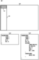
- the display control unit 102 sends a drawing screen 200 for drawing the display screen to the drawing support apparatus 100, as shown in FIG. displayed on an external display. Further, when the reception unit 101 receives information indicating an operation to newly create a component 201 on the drawing screen 200, the display control unit 102 selects the component 201 from the external device attached to the drawing support device 100, as shown in FIG. display it on the display. Further, when the reception unit 101 receives information indicating an operation to newly create a region 202 on the drawing screen 200, the display control unit 102 creates a new area 202 on the drawing support device 100, as shown in FIG. display it on the display.
- the storage unit 103 stores drawing screen information that defines a drawing screen.
- the storage unit 103 is realized by the auxiliary storage unit 13.
- the drawing screen information is information that defines the drawing screen.
- the drawing screen information is generated and updated by the setting unit 104 according to information indicating the operation accepted by the receiving unit 101.
- the drawing screen information includes screen attribute information 1031, component attribute information 1032, and area attribute information 1033. Component attribute information 1032 and area attribute information 1033 are each linked to screen attribute information 1031.
- the screen attribute information 1031 is information that is generated when the user creates a new drawing screen on the drawing support device 100. It includes identification information for identifying the created drawing screen and attribute information indicating the attributes of the drawing screen.
- the attribute information of the drawing screen includes, for example, information indicating the display form of the drawing screen, such as a background image. For example, as shown in FIG. 3, when the user creates a new drawing screen 200 on the drawing support device 100, the setting unit 104 generates screen attribute information 1031 of the drawing screen 200, and stores it in the storage unit 103.
- the component attribute information 1032 is information generated when the user creates a new component on the drawing screen, and includes identification information for identifying the component and attribute information indicating the attribute of the component.
- a component is an element included as an image on a display screen, and includes, for example, something that indicates a specific function such as a switch or a meter, or something that indicates data such as text or a figure.
- the attribute information of a component includes various information that can be set for a component in the drawing software, such as information indicating the display form of the component and information indicating the type of the component.
- the information indicating the display form of the component is, for example, information such as the X coordinate, the Y coordinate of the component, the width of the component, the height of the component, and the color of the component on the drawing screen.
- the X and Y coordinates are set with the upper left corner position 203 of the drawing screen 200 as the origin.
- the information indicating the type of component is, for example, information indicating a function associated with the component, such as a screen changeover switch, a lamp, a numerical display, and the like.
- the setting unit 104 when the user creates a new component 201 on the drawing screen 200, the setting unit 104 generates component attribute information 1032 of the component 201 and stores it in the storage unit 103.
- the area attribute information 1033 is information generated when the user creates a new area on the drawing screen, and includes identification information for identifying the area and attribute information indicating the attributes of the area.
- the attribute information of the area includes information indicating the display form of the area, such as the X coordinate, Y coordinate of the area, width of the area, height of the area, color of the area, etc. on the drawing screen, for example.
- the information indicating the display form of the area includes information specifying the spacing between parts placed within the area, information for aligning the parts placed within the area, and the like. For example, as shown in FIG.
- the setting unit 104 when the user creates a new area 202 by drag-and-drop operation on the drawing screen 200, the setting unit 104 generates area attribute information 1033 for the area 202, and stores it in the storage unit 103. be done. Further, the area attribute information 1033 includes correction information 1033-1 and collection condition information 1033-2, which will be described later, as area attribute information.
- the setting unit 104 sets drawing screen information based on information indicating the operation accepted by the receiving unit 101.
- the setting unit 104 is realized by the processor 11. Note that the setting unit 104 is an example of a setting means.
- the setting unit 104 when the reception unit 101 receives information indicating operations for creating new drawing screens, parts, and areas, the setting unit 104 generates screen attribute information 1031, part attribute information 1032, and area attribute information 1033, and stores them. The information is stored in the section 103. Further, when the receiving unit 101 receives information indicating an operation for specifying attributes of a drawing screen, a component, and an area, the setting unit 104 generates screen attribute information stored in the storage unit 103 based on information indicating the received operation. 1031, component attribute information 1032, and area attribute information 1033 are updated.
- the setting unit 104 also provides correction information 1033-1 for correcting the attribute information of a part that is displayed as an image on the display screen and is placed within a designated area on the drawing screen. Set for area.
- the correction information 1033-1 is information set for a region, and is information for correcting attribute information of parts placed within the region. For example, when correction information 1033-1 is set for the area 202 and an arbitrary part is placed within the area 202, the part attribute information 1032 of the placed part is changed by the changing unit 105 based on the correction information 1033-1. will be changed.
- a window 300 for setting area attribute information 1033 is displayed.
- the window 300 includes a tab 301 for displaying the contents of the correction information 1033-1, a table 302 for displaying the contents of the correction information 1033-1, a button 303 for increasing the contents of the table 302, and a button 303 for increasing the contents of the table 302.
- a tab 307 for displaying contents is included.
- the table 302 attributes indicating items of the component attribute information 1032 and attribute values are registered in association with each other.
- the component attribute information 1032 of the components placed in the area 202 is changed to the attributes and values shown in the table 302.
- the contents of the table 302 are registered by a user's operation.
- the set of attributes and values in the table 302 can be increased by selecting the button 303, and can be decreased by selecting the button 304.
- the first line of the table 302 indicates that the X coordinate of the component attribute information 1032 of the component placed in the area 202 is changed to the same X coordinate as the area 202.
- the values in the spacing column 305 and the alignment column 306 are registered by user operations.
- the interval "5" in the column 305 indicates that, for example, when arranging components within the area 202, an interval of "5" is provided in the upper, lower, right, and left directions.
- the alignment "top alignment” in column 306 indicates that when parts are arranged in area 202, the parts are aligned based on the upper end of area 202.
- the setting unit 104 sets the contents of the table 302 and the contents of spacing and alignment registered by the user's operation as correction information 1033-1, and stores the set correction information 1033-1 in the storage unit 103. do.
- the setting unit 104 sets collection condition information 1033-2, which indicates conditions for attribute information of parts to be collected within the specified area, for the specified area.
- Collection condition information 1033-2 is information set for a region, and is information indicating conditions for attribute information of parts to be collected and placed within the region. For example, when the setting unit 104 sets collection condition information for the area 202 and the user performs a predetermined operation, the changing unit 105 sets the collection condition information for the parts included in the drawing screen 200. A component having component attribute information 1032 that satisfies the indicated conditions is identified, and the component attribute information 1032 of the identified component is changed so that the identified components are collected and arranged within the area 202.
- a table 308 showing the contents of collection condition information and a button 309 are displayed in the window 300, as shown in FIG.
- the table 308 attributes indicating items of the component attribute information 1032 and attribute values are registered in association with each other.
- the component attribute information 1032 of the component included in the drawing screen 200 satisfies the conditions indicated by the attributes and values included in the table 308, the component attribute information 1032 indicating the position of the component is changed so that it is placed within the area 202. be done.
- the contents of the table 308 are registered through user operations. Further, the combination of attributes and values in the table 308 can be increased by selecting the button 303, and can be decreased by selecting the button 304.
- the first row of the table 308 indicates that the component attribute information 1032 is changed so that components whose figure color value is "blue" are collected and arranged within the area 202.
- the button 309 among the parts arranged on the drawing screen 200, parts whose figure color value is "blue” are collected in the area 202.
- the setting unit 104 sets the contents of the table 308 registered by the user's operation as collection condition information 1033-2, and the set collection condition information 1033-2 is stored in the storage unit 103.
- various types of values are employed as the values set as the correction information and collection condition information. For example, a value such as "same as area” or "equal”, a fixed value, or an arithmetic expression is adopted as the value.
- Example 1 in FIG. 5 shows an example where the value is set to "same as area". Assume that the Y coordinate of the region 204 is set as "same as the region" as correction information. In this case, when the component 205 is placed within the area 204, the Y coordinate of the component 205 is set to the same value as the Y coordinate of the area 204. When a component 206 is further placed within the area 204, the Y coordinate of the component 206 is set to the same value as the Y coordinate of the area 204.
- Example 2 in FIG. 5 shows an example where the values are set to "equal". Assume that the height of the area 207 is set to be "equal" as correction information. In this case, when the component 208 is placed within the area 207, the height of the component 208 is set to the same value as the height of the area 207. When another component 209 is placed in the area 207, the heights of the parts 208 and 209 are set to a value obtained by equally dividing the height of the area 207 by the number of parts placed in the area 207. Therefore, the heights of the parts 208 and 209 are each set to half the height of the area 207, that is, the heights are set to be equal.
- Example 3 in FIG. 5 shows an example where the value is set to a fixed value. Assume that the width of the area 210 is set to "40" as correction information. In this case, when the component 211 is placed within the area 210, the width of the component 211 is set to "40". When another component 212 is placed within the area 210, the width of the component 212 is also set to "40".
- Example 4 in FIG. 5 shows an example where the value is set in an arithmetic expression.
- the device is set to "D0+1" as correction information.
- the device refers to data handled in a PLC or a programmable display, for example.
- the arithmetic expression "D0+1" indicates that devices incremented by 1 are associated with added parts based on the device "D0".
- component attribute information 1032 corresponding to the device D0 is set in the component 214.
- component attribute information 1032 corresponding to the device D1 is set in the component 215.
- the value may be set by specifying one of the presented options.
- a comparison calculation expression may be adopted as the calculation expression. For example, graphic color options "blue” and “white” are presented as collection condition information, and a value is set by specifying either option. Further, for example, as the collection condition information, the X coordinate is set as "0 or more and 100 or less".
- the changing unit 105 changes the attribute information of the parts placed within the designated area based on the correction information set by the setting unit 104.
- the changing unit 105 is realized by the processor 11. Note that the changing unit 105 is an example of a changing means.
- the component attribute information 1032 of the component 201 in FIG. 6 has an X coordinate of "20", a Y coordinate of "40", a width of "50", and a height of "50".
- the area attribute information 1033 of the area 202 in FIG. 6 has an X coordinate of "0", a Y coordinate of "0", a width of "100", and a height of "480".
- the correction information included in the area attribute information 1033 of the area 202 in FIG. is set to "top alignment", and the collection condition information is set to "blue” as the figure color.
- the changing unit 105 changes the X coordinate of the component 201 to "0" based on the setting in the correction information that "X coordinate is the same as the area". ” he asks. Furthermore, the changing unit 105 determines the Y coordinate of the component 201 to be “0” based on the setting of "alignment is 'top alignment'” in the correction information. Furthermore, the changing unit 105 determines the width of the component 201 to be "100", which is the same as the width of the region 202, based on the setting in the correction information that "the width is the same as the region".
- the changing unit 105 determines the height of the component 201 to be “40” based on the setting of “height is “40”” in the correction information. Then, the changing unit 105 sets an interval of "5" in the vertical and horizontal directions based on the setting of "interval is '5'” in the correction information, so that the X coordinate of the component 201 is "5" and the Y coordinate is “5". , the width is determined to be "90", and the height is determined to be "30". That is, the changing unit 105 changes the component attribute information 1032 in FIG. 6 as shown in the component attribute information 1032 in FIG. 7.
- the display control unit 102 causes the display device to display the component placed in the designated area based on the attribute information of the component changed by the changing unit 105.
- the display control unit 102 may externally attach a component 201 whose position and size on the drawing screen 200 have been changed based on the changed component attribute information 1032 of FIG. displayed on the screen.
- the changing unit 105 identifies, among the parts displayed on the drawing screen, parts having attribute information that satisfies the conditions indicated by the collection condition information set by the setting unit 104, and attributes of the parts specified by the changing unit 105. Modify the information so that it is placed within the specified area.
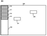
- the area attribute information 1033 of FIG. 6 is set in the area 202 of FIG. 8, and that blue parts 216 to 219 and white parts 220 and 221 are arranged on the drawing screen 200. .
- the user performs a predetermined operation, for example, displays the window 300 in FIG.
- a component having attribute information that satisfies the condition indicated by the collection condition information 1033-2 in the area 202 is identified.
- the condition indicated by the collection condition information 1033-2 in the area 202 is that the figure color is "blue,” so the changing unit 105 changes the component having attribute information that satisfies the condition indicated by the collection condition information 1033-2 in the area 202 to a blue color.
- Parts 216 to 219 are identified. Then, the changing unit 105 changes the X and Y coordinates of the blue components 216 to 219 so that the blue components 216 to 219 are arranged within the area 202, and further changes the component attribute information based on the correction information. Change 1032.
- the display control unit 102 places blue components 216 to 219 within the region 202 at intervals based on the upper end of the region 202 based on the changed component attribute information 1032. "5" is provided, aligned, and displayed on an external display.
- the change process executed by the drawing support apparatus 100 according to the present embodiment will be explained using the flowchart of FIG. 10.
- the change process in FIG. 10 is, for example, a process that is executed when the receiving unit 101 receives information indicating an operation to set the area attribute information 1033 of a specified area on the drawing screen 200.
- the changing unit 105 determines whether a component is placed within the designated area (step S101).
- the changing unit 105 determines that the part is placed within the specified area (step S101; YES)
- the changing unit 105 changes the part placed within the area based on the correction information set for the area.
- the attribute information of is changed (step S102).
- the display control unit 102 displays the component placed in the designated area on the external display based on the changed attribute information of the component (step S103). After that, the process returns to step S101.
- the changing unit 105 determines that no parts are placed within the specified area (step S101; NO)
- the changing unit 105 determines whether an operation to instruct collection of parts has been performed ( Step S104).
- the changing unit 105 determines that the part 201 is placed in the area 202, and changes the correction information 1033 set in the area 202. -1, the component attribute information 1032 of FIG. 6 of the component 201 is changed to the component attribute information 1032 of FIG. 7. Then, the display control unit 102 displays the component 201 on the external display based on the component attribute information 1032 in FIG. 7, as shown in the drawing screen 200 in FIG. On the other hand, if the part 201 is not placed in the area 202, the changing unit 105 determines that the part 201 is not placed in the area 202, and determines whether the button 309 instructing collection has been selected.
- step S104 when the changing unit 105 determines that an operation instructing the collection of parts has been performed (step S104; YES), it identifies parts having attribute information that satisfies the conditions indicated by the set collection condition information (step S105). ). Then, the process proceeds to step 102. On the other hand, in step S104, if the changing unit 105 determines that no operation to instruct collection of parts has been performed (step S104; NO), the process returns to step S101.
- the reception unit 101 receives information indicating an operation of selecting the button 309 in the window 300 of FIG. 1033-2 and the component attribute information 1032 of the components 216 to 221, parts having attribute information satisfying the condition indicated by the collection condition information 1033-2 of the area 202 are identified as blue components 216 to 219. .
- the changing unit 105 changes the X and Y coordinates of the blue components 216 to 219 so that the identified blue components 216 to 219 are arranged within the area 202, and further changes the component attributes based on the correction information. Change information 1032.
- the display control unit 102 causes the blue components 216 to 219 to be displayed on the external display based on the changed component attribute information 1032, as shown in the drawing screen 200 of FIG.
- the area in which each function is placed is determined, such as arranging the menu function side by side on the left side of the display screen, and arranging the title and clock functions at the top of the display screen.
- the user needs to set the attribute information of each component one by one, such as manually adjusting the placement position of the component to be placed in the area.
- the part attribute information of the parts placed in the area is automatically changed based on the area attribute information set in the area, and the parts with the changed part attribute information are displayed on the drawing screen. can do. Thereby, the user can efficiently set the attribute information of the parts within the area without setting the attribute information of the parts individually.
- attribute information regarding the display form of parts can be automatically set. Therefore, it is possible to save the effort of adjusting the appearance of the parts such as size and color, and adjusting the positions of the parts in the area.
- the setting unit 104 sets attribute information of an area including the predetermined component, attribute information of a component attached to the predetermined component, and Attribute information of the area including the attached parts may also be generated.
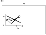
- the predetermined component be a graph component that shows a graph.
- the setting unit 104 generates component attribute information 1032 for character components and button components and area attribute information 1033 for areas 223 to 225, and the display control unit 102 generates the generated component attribute information 1032 and area attribute information. 1033, the parts and regions are displayed on an external display as shown in FIG. Note that the text parts and button parts that are generated in conjunction with the arrangement of the graph parts 222 are set in advance by drawing software.
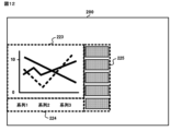
- the method of registering the correction information is not limited to this. Registration of correction information may be performed automatically. For example, if the specified area includes a component placed on the drawing screen, the setting unit 104 assigns common attribute information to the specified area from among the attribute information of the components included in the specified area. It is generated as correction information for.
- correction information is obtained from the parts included in the area 202.
- a window 400 is displayed with a message asking whether or not to generate the file.
- the parts included in the area include not only parts that are entirely included in the area, but also parts that are partially included in the area.
- the setting unit 104 specifies the common attribute information among the attribute information of the parts 226 and 227 included in the area 202 as "figure color is 'blue'".
- the setting unit 104 generates “figure color is blue” as correction information, and the display control unit 102 displays the attribute “figure color” and value in the table 310 of the window 300, as shown in FIG. causes the “blue” group to be displayed on the external display. Thereafter, in window 300 of FIG. 14, the user can add any correction information. For example, when a white component 209 is placed in the area 202 after the setting unit 104 sets the correction information for “figure color is blue”, the changing unit 105 changes the figure color from the component attribute information 1032 of the component 209. Change the color attribute from "white” to "blue”.
- correction information for area attribute information can be automatically generated from the already created drawing screen, it is possible to save time and effort in drawing work, and also reduce the burden of maintenance work on existing screens. be able to.
- correction information and collection condition information are set while the component 201 is placed on the drawing screen 200, but the timing of setting the correction information and collection condition information is as follows. Not limited to. Even if no parts are placed on the drawing screen 200, if the area is set, correction information and collection condition information can be set.
- the interval values in the column 305 are explained as intervals provided in the upper, lower, left, and right directions, but are not limited thereto.
- the direction in which the interval is provided may be configured to be specified in any direction.
- the display control unit 102 is realized by the processor 11 and the input/output interface 15, and the display control unit 102 provides the display device with a drawing screen for drawing a display screen to be displayed on the programmable display.
- the display control unit 102 may be realized by the processor 11 and a display device, and may display a drawing screen. Therefore, the drawing support device 100 may have a hardware configuration including a display device such as a display.
- the reception unit 101 is realized by the processor 11 and the input/output interface 15, and the reception unit 101 accepts information indicating an operation for drawing performed by the user.
- the reception unit 101 is not limited to this. do not have.
- the reception unit 101 may be realized by the processor 11 and an input device, and may accept operations from a user. Therefore, the drawing support device 100 may have a hardware configuration including an input device such as an input key.
- the personal computer or information terminal device can be used as the drawing support device 100 according to the embodiment. It is also possible to make it work.
- the distribution method of such a program is arbitrary; for example, it may be stored and distributed on a computer-readable recording medium such as a CD-ROM (Compact Disk Read-Only Memory), a DVD (Digital Versatile Disk), or a memory card. or distributed via a communication network such as the Internet.
- a computer-readable recording medium such as a CD-ROM (Compact Disk Read-Only Memory), a DVD (Digital Versatile Disk), or a memory card.
- a communication network such as the Internet.
- a drawing support program and drawing support program that can efficiently set attribute information of parts included as an image on a display screen, A support device and a drawing support method can be provided.
Landscapes
- Engineering & Computer Science (AREA)
- Physics & Mathematics (AREA)
- General Physics & Mathematics (AREA)
- Geometry (AREA)
- Theoretical Computer Science (AREA)
- Mathematical Optimization (AREA)
- General Engineering & Computer Science (AREA)
- Mathematical Analysis (AREA)
- Human Computer Interaction (AREA)
- Pure & Applied Mathematics (AREA)
- Computer Hardware Design (AREA)
- Evolutionary Computation (AREA)
- Computational Mathematics (AREA)
- Architecture (AREA)
- Automation & Control Theory (AREA)
- User Interface Of Digital Computer (AREA)
- Testing And Monitoring For Control Systems (AREA)
- Programmable Controllers (AREA)
- Image Generation (AREA)
Priority Applications (4)
| Application Number | Priority Date | Filing Date | Title |
|---|---|---|---|
| JP2022547957A JP7186933B1 (ja) | 2022-04-04 | 2022-04-04 | 作画支援プログラム、作画支援装置及び作画支援方法 |
| CN202280085056.4A CN118435139B (zh) | 2022-04-04 | 2022-04-04 | 绘图辅助程序产品、绘图辅助装置及绘图辅助方法 |
| PCT/JP2022/017061 WO2023195050A1 (ja) | 2022-04-04 | 2022-04-04 | 作画支援プログラム、作画支援装置及び作画支援方法 |
| DE112022005269.4T DE112022005269B4 (de) | 2022-04-04 | 2022-04-04 | Aufzeichnungsmedium, Zeichenunterstützungs-Gerät und Zeichenunterstützungs-Verfahren |
Applications Claiming Priority (1)
| Application Number | Priority Date | Filing Date | Title |
|---|---|---|---|
| PCT/JP2022/017061 WO2023195050A1 (ja) | 2022-04-04 | 2022-04-04 | 作画支援プログラム、作画支援装置及び作画支援方法 |
Publications (1)
| Publication Number | Publication Date |
|---|---|
| WO2023195050A1 true WO2023195050A1 (ja) | 2023-10-12 |
Family
ID=84388166
Family Applications (1)
| Application Number | Title | Priority Date | Filing Date |
|---|---|---|---|
| PCT/JP2022/017061 Ceased WO2023195050A1 (ja) | 2022-04-04 | 2022-04-04 | 作画支援プログラム、作画支援装置及び作画支援方法 |
Country Status (4)
| Country | Link |
|---|---|
| JP (1) | JP7186933B1 (https=) |
| CN (1) | CN118435139B (https=) |
| DE (1) | DE112022005269B4 (https=) |
| WO (1) | WO2023195050A1 (https=) |
Citations (3)
| Publication number | Priority date | Publication date | Assignee | Title |
|---|---|---|---|---|
| US6088027A (en) * | 1998-01-08 | 2000-07-11 | Macromedia, Inc. | Method and apparatus for screen object manipulation |
| JP2006099573A (ja) * | 2004-09-30 | 2006-04-13 | Digital Electronics Corp | 画面作成装置、画面作成プログラムおよびそれを記録した記録媒体 |
| JP2006099566A (ja) * | 2004-09-30 | 2006-04-13 | Digital Electronics Corp | 画面作成装置、画面作成プログラムおよびそれを記録した記録媒体 |
Family Cites Families (12)
| Publication number | Priority date | Publication date | Assignee | Title |
|---|---|---|---|---|
| JP3715144B2 (ja) * | 1999-08-27 | 2005-11-09 | 株式会社デジタル | 描画装置および描画処理のためのプログラムを記録した記録媒体 |
| JP5180039B2 (ja) * | 2008-11-27 | 2013-04-10 | 株式会社デジタル | 画面データエディタ装置および画面データエディタプログラム |
| JP2011043934A (ja) * | 2009-08-20 | 2011-03-03 | Fujitsu Ltd | 図面修正支援プログラム及び図面修正支援装置 |
| JP2011054075A (ja) * | 2009-09-04 | 2011-03-17 | Olympus Imaging Corp | 画像制御装置およびプログラム |
| JP5152436B2 (ja) * | 2010-06-08 | 2013-02-27 | 三菱電機株式会社 | プログラマブル表示器の画面作成システム及びその画面作成プログラム |
| JP5144816B2 (ja) * | 2011-03-02 | 2013-02-13 | 三菱電機株式会社 | プログラマブル表示器、及び作画データの作成方法 |
| JP5806061B2 (ja) * | 2011-09-28 | 2015-11-10 | 発紘電機株式会社 | プログラマブル表示器の支援装置、そのプログラム、操作画面一括変更支援方法 |
| JP6068758B2 (ja) | 2014-06-26 | 2017-01-25 | 株式会社デジタル | プログラマブル表示器 |
| JP6428766B2 (ja) * | 2015-03-12 | 2018-11-28 | 富士電機株式会社 | 表示装置、監視システム、表示方法および表示プログラム |
| WO2018163311A1 (ja) * | 2017-03-08 | 2018-09-13 | 三菱電機株式会社 | 作画支援装置、表示システムおよび作画支援方法 |
| JP6878367B2 (ja) * | 2018-08-29 | 2021-05-26 | ファナック株式会社 | 数値制御装置 |
| JP7456213B2 (ja) * | 2020-03-16 | 2024-03-27 | 富士フイルムビジネスイノベーション株式会社 | 情報処理装置及びプログラム |
-
2022
- 2022-04-04 DE DE112022005269.4T patent/DE112022005269B4/de active Active
- 2022-04-04 CN CN202280085056.4A patent/CN118435139B/zh active Active
- 2022-04-04 WO PCT/JP2022/017061 patent/WO2023195050A1/ja not_active Ceased
- 2022-04-04 JP JP2022547957A patent/JP7186933B1/ja active Active
Patent Citations (3)
| Publication number | Priority date | Publication date | Assignee | Title |
|---|---|---|---|---|
| US6088027A (en) * | 1998-01-08 | 2000-07-11 | Macromedia, Inc. | Method and apparatus for screen object manipulation |
| JP2006099573A (ja) * | 2004-09-30 | 2006-04-13 | Digital Electronics Corp | 画面作成装置、画面作成プログラムおよびそれを記録した記録媒体 |
| JP2006099566A (ja) * | 2004-09-30 | 2006-04-13 | Digital Electronics Corp | 画面作成装置、画面作成プログラムおよびそれを記録した記録媒体 |
Also Published As
| Publication number | Publication date |
|---|---|
| JP7186933B1 (ja) | 2022-12-09 |
| DE112022005269T5 (de) | 2024-11-21 |
| CN118435139B (zh) | 2025-06-27 |
| DE112022005269B4 (de) | 2025-11-13 |
| JPWO2023195050A1 (https=) | 2023-10-12 |
| CN118435139A (zh) | 2024-08-02 |
Similar Documents
| Publication | Publication Date | Title |
|---|---|---|
| EP0249399B1 (en) | Multiwindow control method and apparatus for work station having multiwindow function | |
| JPS6324462A (ja) | ウインドウ状態表示方式 | |
| JP2014032529A (ja) | Plcシステム、その作画エディタ装置、プログラマブル表示器 | |
| US10635227B2 (en) | Image display device | |
| CN112000328B (zh) | 一种页面可视化编辑方法、装置及设备 | |
| WO2023195050A1 (ja) | 作画支援プログラム、作画支援装置及び作画支援方法 | |
| JP4331272B2 (ja) | マルチウインドウ表示制御装置 | |
| CN113064567A (zh) | 一种基于多屏的控制方法和装置 | |
| JP2021096291A (ja) | 表示装置、表示システム、及び表示方法 | |
| WO2024000111A1 (zh) | 桌面展示方法、电子设备、显示装置及计算机可读存储介质 | |
| US20170255340A1 (en) | Information processing apparatus, and control method and control program thereof | |
| JP2004029933A (ja) | 表示制御装置および表示制御方法 | |
| CN112799526A (zh) | 一种单系统多鼠标同时显示操作的方法和系统 | |
| JP2002268737A (ja) | インテリジェント型グラフィック操作パネル及び部品表示方法。 | |
| JP7415086B1 (ja) | 作画支援プログラム、作画支援装置及び作画支援方法 | |
| CN112486330B (zh) | 显示控制方法、装置及设备 | |
| JP2006195512A (ja) | 表示制御装置及び表示制御プログラム | |
| JP3100218B2 (ja) | 出力データ項目区切り処理方法 | |
| JP3807052B2 (ja) | 図形描画装置、及び記憶媒体 | |
| JP2022056059A (ja) | 情報処理装置及びプログラム | |
| JPH0785306A (ja) | Cad作図装置 | |
| JPS6068375A (ja) | 表示装置の画面制御方式 | |
| JP2000347777A (ja) | データ入力画面の表示方法 | |
| JPH04307659A (ja) | データ表示方式 | |
| JPS63163665A (ja) | 表作成装置 |
Legal Events
| Date | Code | Title | Description |
|---|---|---|---|
| WWE | Wipo information: entry into national phase |
Ref document number: 2022547957 Country of ref document: JP |
|
| 121 | Ep: the epo has been informed by wipo that ep was designated in this application |
Ref document number: 22936452 Country of ref document: EP Kind code of ref document: A1 |
|
| WWE | Wipo information: entry into national phase |
Ref document number: 202280085056.4 Country of ref document: CN |
|
| WWE | Wipo information: entry into national phase |
Ref document number: 112022005269 Country of ref document: DE |
|
| 122 | Ep: pct application non-entry in european phase |
Ref document number: 22936452 Country of ref document: EP Kind code of ref document: A1 |
|
| WWG | Wipo information: grant in national office |
Ref document number: 202280085056.4 Country of ref document: CN |
|
| WWG | Wipo information: grant in national office |
Ref document number: 112022005269 Country of ref document: DE |